JP2012147180A - Device and method for identifying image position, and device and method for embedding alignment signal - Google Patents
Device and method for identifying image position, and device and method for embedding alignment signal Download PDFInfo
- Publication number
- JP2012147180A JP2012147180A JP2011003068A JP2011003068A JP2012147180A JP 2012147180 A JP2012147180 A JP 2012147180A JP 2011003068 A JP2011003068 A JP 2011003068A JP 2011003068 A JP2011003068 A JP 2011003068A JP 2012147180 A JP2012147180 A JP 2012147180A
- Authority
- JP
- Japan
- Prior art keywords
- image
- alignment signal
- signal pattern
- parallel movement
- peak
- Prior art date
- Legal status (The legal status is an assumption and is not a legal conclusion. Google has not performed a legal analysis and makes no representation as to the accuracy of the status listed.)
- Pending
Links
- 238000000034 method Methods 0.000 title claims description 71
- 238000001228 spectrum Methods 0.000 claims abstract description 159
- 238000011156 evaluation Methods 0.000 claims abstract description 73
- 238000012545 processing Methods 0.000 claims abstract description 56
- 238000013519 translation Methods 0.000 claims description 36
- 238000012854 evaluation process Methods 0.000 claims description 14
- 230000003595 spectral effect Effects 0.000 claims description 7
- 239000000284 extract Substances 0.000 claims 1
- 230000004807 localization Effects 0.000 claims 1
- 238000006073 displacement reaction Methods 0.000 abstract description 6
- 238000004364 calculation method Methods 0.000 description 44
- 230000009467 reduction Effects 0.000 description 27
- 230000008569 process Effects 0.000 description 24
- 238000001514 detection method Methods 0.000 description 18
- 238000010586 diagram Methods 0.000 description 9
- 230000000694 effects Effects 0.000 description 6
- 230000006870 function Effects 0.000 description 6
- 101100533306 Mus musculus Setx gene Proteins 0.000 description 3
- 230000006835 compression Effects 0.000 description 3
- 238000007906 compression Methods 0.000 description 3
- 230000008901 benefit Effects 0.000 description 2
- 239000004065 semiconductor Substances 0.000 description 2
- 238000012360 testing method Methods 0.000 description 2
- 230000009466 transformation Effects 0.000 description 2
- 230000001131 transforming effect Effects 0.000 description 2
- 238000012935 Averaging Methods 0.000 description 1
- 230000003466 anti-cipated effect Effects 0.000 description 1
- 230000015556 catabolic process Effects 0.000 description 1
- 230000008602 contraction Effects 0.000 description 1
- 238000006731 degradation reaction Methods 0.000 description 1
- 230000006866 deterioration Effects 0.000 description 1
- 238000003709 image segmentation Methods 0.000 description 1
- 238000013507 mapping Methods 0.000 description 1
- 238000012986 modification Methods 0.000 description 1
- 230000004048 modification Effects 0.000 description 1
- 230000001360 synchronised effect Effects 0.000 description 1
- 238000009966 trimming Methods 0.000 description 1
Images


Landscapes
- Image Analysis (AREA)
- Image Processing (AREA)
- Editing Of Facsimile Originals (AREA)
Abstract
Description
この発明は、電子透かしが埋め込まれているデジタル画像に対して編集処理(例えば、拡大縮小(スケーリング)、回転、反転、切取(トリミング)など)が施されていて、電子透かしを検出する画像の位置を特定できないような場合に、そのデジタル画像に埋め込まれている位置合わせ信号パターンを検出して、その画像の位置を特定する画像位置特定装置及び方法と、位置合わせ信号パターンをデジタル画像に埋め込む位置合わせ信号埋込装置及び方法とに関するものである。 In the present invention, an editing process (for example, enlargement / reduction (scaling), rotation, inversion, cropping) is performed on a digital image in which a digital watermark is embedded, and the digital watermark is detected. In a case where the position cannot be specified, an alignment signal pattern embedded in the digital image is detected, and an image position specifying device and method for specifying the position of the image, and the alignment signal pattern are embedded in the digital image. The present invention relates to an alignment signal embedding apparatus and method.
電子透かしが埋め込まれているデジタル画像に対して編集処理(例えば、拡大縮小(スケーリング)、回転、反転、切取(トリミング)など)が施されている場合、そのデジタル画像に埋め込まれている電子透かしの位置を特定することができないことがある。
このような場合に対処するため、電子透かしのデータとは別に、位置合わせ信号パターン(レジストレーション信号)が電子透かしとしてデジタル画像に埋め込まれることがある。
デジタル画像に埋め込まれている電子透かしを検出する際、その位置合わせ信号パターンを検出することで、電子透かしのデータが埋め込まれている画像の位置を特定する画像位置特定装置が以下の特許文献1,2に開示されている。
When an editing process (for example, enlargement / reduction (scaling), rotation, inversion, cropping) is performed on a digital image in which the digital watermark is embedded, the digital watermark embedded in the digital image It may not be possible to specify the position of.
In order to cope with such a case, a registration signal pattern (registration signal) may be embedded in a digital image as a digital watermark separately from the digital watermark data.
特許文献1,2に開示されている画像位置特定装置では、切取の編集に伴って必要となっている位置合わせについては、相関演算又は2次元離散フーリエ変換を実施することで行っている。
また、拡大縮小、回転又は反転の編集に伴って必要となっている位置合わせについては、2次元離散フーリエ変換を実施することで行っている。
In the image position specifying devices disclosed in
In addition, the alignment necessary for the enlargement / reduction, rotation, or inversion editing is performed by performing a two-dimensional discrete Fourier transform.
従来の画像位置特定装置は以上のように構成されているので、切取の編集に伴う位置合わせを行う場合、相関演算又は2次元離散フーリエ変換を実施するが、相関演算又は2次元離散フーリエ変換を実施する方法では、計算量が膨大であるため、位置合わせが完了するまでに多くの時間を要する課題があった。 Since the conventional image position specifying apparatus is configured as described above, when performing alignment according to clipping editing, correlation calculation or two-dimensional discrete Fourier transform is performed, but correlation calculation or two-dimensional discrete Fourier transform is performed. In the method to be implemented, since the calculation amount is enormous, there is a problem that it takes a long time to complete the alignment.
即ち、特許文献2では、拡大縮小、回転又は反転の編集に伴う位置合わせに2次元離散フーリエ変換を利用し、切取の編集に伴う位置合わせに相関演算を利用している。この場合、例えば、位置合わせ信号パターンの繰り返し周期を横Mピクセル、縦Nピクセルとすると、2次元離散フーリエ変換の計算量がO(MN・log(MN))であるのに対して、相関演算によって相関値のピーク位置を探す計算量がO(M2N2)であるため、切取の編集に伴う位置合わせが計算量上のボトルネックになる。そのため、切取の編集に伴う位置合わせについても、2次元離散フーリエ変換を利用することが望ましい。
特許文献1では、切取の編集に伴う位置合わせに2次元離散フーリエ変換を利用しているが、数学的内容(式(32)を最小化する位置を求めること)が開示されているのみであり、デジタル画像をデジタル計算機で扱う上で、高速に実施する方法については開示されていない。そのため、全ての位置(MN通りの位置)において、同式を評価しなければならないと考えられ、計算量がO(MN)となる。即ち、位置合わせ信号パターンが有する周波数スペクトルの数をsとすると、計算量がO(MNs)となる。相関演算を利用する場合の計算量がO(M2N2)であるため、計算量が多少軽減されてはいるが、特許文献1に開示されている式(32)は三角関数計算を含む複雑な演算が必要である。
That is, in
In
この発明は上記のような課題を解決するためになされたもので、切取の編集に伴う位置合わせの高速化を図ることができる画像位置特定装置及び画像位置特定方法を得ることを目的とする。
また、この発明は、切取の編集に伴う位置合わせに利用する位置合わせ信号パターンをデジタル画像に埋め込むことができる位置合わせ信号埋込装置及び位置合わせ信号埋込方法を得ることを目的とする。
The present invention has been made to solve the above-described problems, and an object of the present invention is to provide an image position specifying apparatus and an image position specifying method capable of speeding up the alignment accompanying editing of cuts.
Another object of the present invention is to provide an alignment signal embedding device and an alignment signal embedding method that can embed an alignment signal pattern used for alignment associated with editing of a cutout in a digital image.
この発明に係る画像位置特定装置は、原画像に対して編集が施されている可能性がある画像を入力し、その入力画像から一部の画像を切り出すことで、原画像に埋め込まれている位置合わせ信号パターンと同じ大きさの部分画像を生成する部分画像生成手段と、部分画像生成手段により生成された部分画像をフーリエ変換し、そのフーリエ変換結果であるフーリエ係数を出力するフーリエ変換手段と、フーリエ変換手段から出力されたフーリエ係数の中で、絶対値が突出しているフーリエ係数の座標であるピーク座標を特定するピーク座標特定手段と、位置合わせ信号パターンにおける周波数スペクトルの周波数平面上での座標であるスペクトル座標の中で、ピーク座標特定手段により特定されたピーク座標と対応関係があるスペクトル座標を特定する対応関係特定手段と、対応関係特定手段により対応関係が特定されたピーク座標と周波数スペクトルの各組み合わせに対する評価処理を実行するに際して、その評価処理を実行する組み合わせの順序を上記ピーク座標におけるフーリエ係数に基づいて決定する評価順序決定手段とを設け、平行移動量特定手段が、評価順序決定手段により決定された順序が先の組み合わせから順番に、当該組み合わせに係るピーク座標と周波数スペクトルを、原画像に対する入力画像の平行移動量によって評価値が変化する評価式に代入して、その評価式が成立するか否かを判別することで、入力画像の平行移動量の全候補の中から、平行移動量の絞り込みを行うようにしたものである。 An image position specifying device according to the present invention is embedded in an original image by inputting an image that may be edited on the original image and cutting out a part of the image from the input image. A partial image generating means for generating a partial image having the same size as the alignment signal pattern; and a Fourier transform means for performing a Fourier transform on the partial image generated by the partial image generating means and outputting a Fourier coefficient as a result of the Fourier transformation. Among the Fourier coefficients output from the Fourier transform means, the peak coordinate specifying means for specifying the peak coordinates, which are the coordinates of the Fourier coefficients whose absolute values are prominent, and the frequency spectrum of the frequency spectrum in the alignment signal pattern on the frequency plane Spectral coordinates corresponding to the peak coordinates specified by the peak coordinate specifying means in the spectrum coordinates that are coordinates When executing the evaluation process for each combination of the corresponding relationship specifying means and the peak coordinates and the frequency spectrum for which the corresponding relation is specified by the corresponding relation specifying means, the order of the combinations for executing the evaluation processes is determined by the Fourier in the peak coordinates. An evaluation order determining means for determining based on the coefficient, and the parallel movement amount specifying means is configured to generate the peak coordinates and the frequency spectrum relating to the combination in the order determined by the evaluation order determining means in order from the previous combination. By substituting into an evaluation formula whose evaluation value changes depending on the amount of translation of the input image relative to the image, and determining whether the evaluation formula is satisfied, it is possible to select a parallel translation from all the candidates for the translation of the input image. The movement amount is narrowed down.
この発明によれば、原画像に対して編集が施されている可能性がある画像を入力し、その入力画像から一部の画像を切り出すことで、原画像に埋め込まれている位置合わせ信号パターンと同じ大きさの部分画像を生成する部分画像生成手段と、部分画像生成手段により生成された部分画像をフーリエ変換し、そのフーリエ変換結果であるフーリエ係数を出力するフーリエ変換手段と、フーリエ変換手段から出力されたフーリエ係数の中で、絶対値が突出しているフーリエ係数の座標であるピーク座標を特定するピーク座標特定手段と、位置合わせ信号パターンにおける周波数スペクトルの周波数平面上での座標であるスペクトル座標の中で、ピーク座標特定手段により特定されたピーク座標と対応関係があるスペクトル座標を特定する対応関係特定手段と、対応関係特定手段により対応関係が特定されたピーク座標と周波数スペクトルの各組み合わせに対する評価処理を実行するに際して、その評価処理を実行する組み合わせの順序を上記ピーク座標におけるフーリエ係数に基づいて決定する評価順序決定手段とを設け、平行移動量特定手段が、評価順序決定手段により決定された順序が先の組み合わせから順番に、当該組み合わせに係るピーク座標と周波数スペクトルを、原画像に対する入力画像の平行移動量によって評価値が変化する評価式に代入して、その評価式が成立するか否かを判別することで、入力画像の平行移動量の全候補の中から、平行移動量の絞り込みを行うように構成したので、切取の編集に伴う位置合わせの高速化を図ることができる効果がある。 According to the present invention, an alignment signal pattern embedded in an original image is input by inputting an image that may be edited with respect to the original image and cutting out a part of the image from the input image. A partial image generating means for generating a partial image of the same size as the above, a Fourier transform means for performing a Fourier transform on the partial image generated by the partial image generating means, and outputting a Fourier coefficient as a result of the Fourier transform, and a Fourier transform means Among the Fourier coefficients output from, the peak coordinate specifying means for specifying the peak coordinates that are the coordinates of the Fourier coefficients with the protruding absolute value, and the spectrum that is the coordinates on the frequency plane of the frequency spectrum in the alignment signal pattern Among the coordinates, the correspondence that specifies the spectral coordinates that have a corresponding relationship with the peak coordinates specified by the peak coordinate specifying means. When executing the evaluation process for each combination of the peak coordinates and the frequency spectrum for which the correspondence relation is specified by the specifying means and the corresponding relation specifying means, the order of the combination for executing the evaluation process is based on the Fourier coefficient in the peak coordinates. An evaluation order determining means for determining, and the parallel movement amount specifying means is configured so that the order determined by the evaluation order determining means is in order from the previous combination, and the peak coordinates and frequency spectrum related to the combination are input to the original image. By substituting into an evaluation formula that changes the evaluation value depending on the amount of parallel translation of the input image and determining whether or not the evaluation formula is satisfied, the translation amount can be narrowed down from all the candidates for the translation amount of the input image. Therefore, there is an effect that it is possible to speed up the alignment accompanying the editing of the cutout.
実施の形態1.
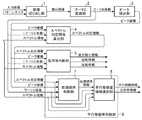
図1はこの発明の実施の形態1による画像位置特定装置を示す構成図である。
図1において、画像切り出し部1はデジタル画像である原画像に対して編集が施されている可能性がある画像を入力し、その入力画像から一部の画像を切り出すことで、その原画像に埋め込まれている位置合わせ信号パターンと同じ大きさの部分画像を生成する処理を実施する。なお、画像切り出し部1は部分画像生成手段を構成している。
1 is a block diagram showing an image position specifying apparatus according to
In FIG. 1, an
フーリエ変換部2は画像切り出し部1により生成された部分画像をフーリエ変換し、そのフーリエ変換結果であるフーリエ係数を出力する処理を実施する。なお、フーリエ変換部2はフーリエ変換手段を構成している。
ピーク検出部3はフーリエ変換部2から出力されたフーリエ係数の中で、絶対値が突出しているフーリエ係数の周波数平面上での座標であるピーク座標を特定する処理を実施する。なお、ピーク検出部3はピーク座標特定手段を構成している。
The Fourier
The
スペクトル対応関係算出部4は位置合わせ信号パターンにおける周波数スペクトルの周波数平面上での座標であるスペクトル座標の中で、ピーク検出部3により特定されたピーク座標と対応関係があるスペクトル座標を特定する処理を実施する。なお、スペクトル対応関係算出部4は対応関係特定手段を構成している。
拡大等判断部5はスペクトル対応関係算出部4により対応関係が特定されたピーク座標と周波数スペクトルの組み合わせから、原画像に対する入力画像の拡大縮小、回転及び反転を特定する処理を実施する。なお、拡大等判断部5は拡大等特定手段を構成している。
The spectrum
The
平行移動等判断部6は原画像に対する入力画像の平行移動量と、点対称移動の有無とを特定する処理を実施する。
処理順序判断部7はスペクトル対応関係算出部4により対応関係が特定されたピーク座標と周波数スペクトルの各組み合わせに対する評価処理を実行するに際して、その評価処理を実行する組み合わせの順序をピーク座標におけるフーリエ係数に基づいて決定する処理を実行する。なお、処理順序判断部7は評価順序決定手段を構成している。
The parallel
When executing the evaluation process for each combination of the peak coordinate and the frequency spectrum for which the correspondence relationship is specified by the spectrum
平行移動量候補選択部8は処理順序判断部7により決定された順序が先の組み合わせから順番に、当該組み合わせに係るピーク座標と周波数スペクトルを、原画像に対する入力画像の平行移動量によって評価値が変化する評価式に代入して、その評価式が成立するか否かを判別することで、入力画像の平行移動量の全候補の中から、平行移動量の絞り込みを行う。
また、平行移動量候補選択部8はスペクトル対応関係算出部4により特定された対応関係と点対称となる組み合わせに係るピーク座標と周波数スペクトルについても評価式に代入して、その評価式が成立するか否かを判別することで、入力画像の平行移動量の全候補の中から、平行移動量の絞り込みを行う。
平行移動量候補選択部8は最終的に絞り込んだ平行移動量に係るピーク座標と周波数スペクトルの組み合わせから点対称移動の有無を判別する処理を実施する。
なお、平行移動量候補選択部8は平行移動量特定手段を構成している。
The parallel movement amount
The parallel movement amount
The parallel movement amount
The translation amount
図1の例では、画像位置特定装置の構成要素である画像切り出し部1、フーリエ変換部2、ピーク検出部3、スペクトル対応関係算出部4、拡大等判断部5及び平行移動等判断部6のそれぞれが専用のハードウェア(例えば、CPUを実装している半導体集積回路、あるいは、ワンチップマイコンなど)で構成されているものを想定しているが、画像位置特定装置がコンピュータなどで構成される場合には、画像切り出し部1、フーリエ変換部2、ピーク検出部3、スペクトル対応関係算出部4、拡大等判断部5及び平行移動等判断部6の処理内容を記述しているプログラムの全部又は一部をコンピュータのメモリに格納し、当該コンピュータのCPUが当該メモリに格納されているプログラムを実行するようにしてもよい。
図2はこの発明の実施の形態1による画像位置特定装置の処理内容(画像位置特定方法)を示すフローチャートである。
In the example of FIG. 1, the
FIG. 2 is a flowchart showing the processing contents (image position specifying method) of the image position specifying apparatus according to
次に動作について説明する。
この実施の形態1では、拡大縮小、回転、反転、切取などの編集が施された可能性があるデジタル画像である原画像(非圧縮輝度画像)に対して、電子透かしとして埋め込まれている位置合わせ信号パターンを検出して位置合わせを行う画像位置特定装置について説明する。
Next, the operation will be described.
In the first embodiment, a position embedded as a digital watermark with respect to an original image (uncompressed luminance image) that is a digital image that may be edited such as enlargement / reduction, rotation, inversion, or cropping An image position specifying device that performs alignment by detecting an alignment signal pattern will be described.
最初に、前提となる2次元離散フーリエ変換による位置合わせの理論について説明する。
ここでは、位置合わせ信号パターンは、横がMピクセル、縦がMピクセルの正方形のパターンであり、s個の周波数スペクトルSi(i∈[1,s])を含むパターンであるとする。
位置合わせ信号パターンは、一般的には長方形でもよいが、多くの実装において、正方形とされているため、以下の説明では、位置合わせ信号パターンが正方形であるとする。
また、周波数スペクトルSi(Siは複素数)は、周波数平面上で位置(Xi,Yi)(Xi∈[1,M/2−1])にあるとする。Mはパターンサイズである。
画像に足し合わせる位置合わせ信号パターンは実数であるため、必然的に周波数平面上(−Xi,−Yi)に周波数スペクトルSiの共役複素数の周波数スペクトルが配置される。
First, the theory of alignment based on the two-dimensional discrete Fourier transform as a premise will be described.
Here, it is assumed that the alignment signal pattern is a square pattern having M pixels in the horizontal direction and M pixels in the vertical direction, and includes s frequency spectra Si (iε [1, s]).
The alignment signal pattern may generally be a rectangle, but in many implementations it is a square, so in the following description, the alignment signal pattern is assumed to be a square.
Further, it is assumed that the frequency spectrum Si (Si is a complex number) is at a position (Xi, Yi) (Xiε [1, M / 2-1]) on the frequency plane. M is the pattern size.
Since the alignment signal pattern added to the image is a real number, a frequency spectrum of a conjugate complex number of the frequency spectrum Si is necessarily arranged on the frequency plane (−Xi, −Yi).
位置合わせ信号パターンがf(x,y)であるとすると、位置合わせ信号パターンf(x,y)のフーリエ変換F(X,Y)は下記のようになる。
f(x,y) (x∈[−M/2,M/2−1],y∈[−M/2,M/2−1])
F(X,Y) (X∈[−M/2,M/2−1],Y∈[−M/2,M/2−1])
F(X,Y)=Si((X,Y)∈{(Xi,Yi)|i∈[1,s]})
Siの共役複素数((X,Y)∈{(−Xi,−Yi)|i∈[1,s]})
0(その他の(X,Y))
Assuming that the alignment signal pattern is f (x, y), the Fourier transform F (X, Y) of the alignment signal pattern f (x, y) is as follows.
f (x, y) (x∈ [−M / 2, M / 2-1], y∈ [−M / 2, M / 2-1])
F (X, Y) (X∈ [−M / 2, M / 2-1], Y∈ [−M / 2, M / 2-1])
F (X, Y) = Si ((X, Y) ε {(Xi, Yi) | iε [1, s]})
Conjugated complex number of Si ((X, Y) ∈ {(− Xi, −Yi) | i∈ [1, s]})
0 (other (X, Y))
また、フーリエ変換及び逆フーリエ変換は、下記の通りである。
F(X,Y)
=(1/M)Σ(x,y)f(x,y)exp(−j2πxX/M)exp(−j2πyY/M)
f(x,y)
=(1/M)Σ(X,Y)F(X,Y)exp(j2πxX/M)exp(j2πyY/M)
ただし、jは虚数単位、πは円周率、exp()は底がネイピア数の指数関数である。
The Fourier transform and inverse Fourier transform are as follows.
F (X, Y)
= (1 / M) Σ (x, y) f (x, y) exp (−j2πxX / M) exp (−j2πyY / M)
f (x, y)
= (1 / M) Σ (X, Y) F (X, Y) exp (j2πxX / M) exp (j2πyY / M)
Here, j is an imaginary unit, π is a pi, and exp () is an exponential function with the number of Napiers at the bottom.
この実施の形態1では、横Mピクセル、縦Mピクセルの位置合わせ信号パターンf(x,y)を循環的に原画像に加算する。原画像の特性に応じて、検出精度や主観画質を向上させるために画素毎に重みを調整しながら加算するようにしてもよい。
位置合わせは、入力画像(原画像に対して編集が施されている可能性がある画像)の任意の横Mピクセル、縦Mピクセルの正方形部分を対象に行う。
その正方形部分をフーリエ変換し、周波数スペクトルの絶対値(振幅)を調べると、位置合わせ用の周波数スペクトルの位置を検出することができる。この検出は、周波数スペクトルの絶対値マップにおいて、絶対値が突出している座標をピックアップする作業であり、公知の画像処理技術によって十分可能であるため、その方法の詳細についての説明を割愛する。
In the first embodiment, the alignment signal pattern f (x, y) of horizontal M pixels and vertical M pixels is cyclically added to the original image. Depending on the characteristics of the original image, addition may be performed while adjusting the weight for each pixel in order to improve detection accuracy and subjective image quality.
The alignment is performed on a square portion of an arbitrary horizontal M pixel and vertical M pixel of the input image (an image that may be edited on the original image).
When the square portion is Fourier-transformed and the absolute value (amplitude) of the frequency spectrum is examined, the position of the frequency spectrum for alignment can be detected. This detection is an operation of picking up the coordinates where the absolute value protrudes in the absolute value map of the frequency spectrum, and can be sufficiently performed by a known image processing technique. Therefore, the detailed description of the method is omitted.
検出した周波数スペクトルの数をt、周波数スペクトルをTk(k∈[1,t])とし、原画像がある角度だけ回転されていれば、周波数スペクトルSiの周波数平面上での位置は原点を中心に同じ角度だけ回転され、原画像がある対称線を軸に反転されていれば、周波数スペクトルSiの周波数平面上での位置は同じ角度で原点を通る対称線を軸に反転される。
また、原画像がある拡大率で拡大されていれば、周波数スペクトルSiの周波数平面上での位置は原点を中心に、その拡大率の逆数の拡大率で拡大される(周波数スペクトルSiの周波数平面上での原点からの距離は画像の拡大率の逆数倍となる)。
この性質を利用し、入力画像が原画像に対して、どのように拡大縮小、回転、反転されたかを判断することができる。これらの判断方法の詳細については、特許文献1,2などに開示されているため説明を割愛する。
If the number of detected frequency spectra is t, the frequency spectrum is Tk (k∈ [1, t]), and the original image is rotated by a certain angle, the position of the frequency spectrum Si on the frequency plane is centered on the origin. If the original image is rotated about the same symmetry line as the axis, the position of the frequency spectrum Si on the frequency plane is inverted about the symmetry line passing through the origin at the same angle.
Further, if the original image is magnified at a certain magnification, the position of the frequency spectrum Si on the frequency plane is magnified with the magnification of the reciprocal of the magnification rate centered on the origin (frequency plane of the frequency spectrum Si). The distance from the origin above is the inverse of the image magnification).
Using this property, it is possible to determine how the input image has been scaled, rotated, or inverted with respect to the original image. Details of these determination methods are disclosed in
検出した周波数スペクトルTkの位置から判断した拡大率、回転角、反転軸の角度に基づいて入力画像を補正することで、平行移動の不確定性だけが残された状態まで補正することができる。
以下、平行移動の不確定性だけが残された状態まで補正した画像を「半補正画像」と称する。
半補正画像は、原画像からx軸方向にmピクセル(m∈[−M/2,M/2−1])、y軸方向にnピクセル(n∈[−M/2,M/2−1])だけ平行移動されているとすると、このm,nを求めることが、平行移動に対する位置合わせに相当する。
By correcting the input image based on the magnification, rotation angle, and reversal axis angle determined from the position of the detected frequency spectrum Tk, it is possible to correct the state in which only the uncertainty of translation remains.
Hereinafter, an image that has been corrected to a state where only the uncertainty of translation remains is referred to as a “half-corrected image”.
The half-corrected image has m pixels (m∈ [−M / 2, M / 2-1]) in the x-axis direction and n pixels (n∈ [−M / 2, M / 2−2) in the y-axis direction from the original image. 1]), it is assumed that obtaining m and n corresponds to alignment with respect to the parallel movement.
拡大縮小、回転、反転がなされている場合の他、拡大縮小、回転、反転がなされていない場合であっても切取(トリミング)がなされている場合には、この位置合わせが必要となる。
ここで、周波数スペクトルTkに対応する周波数スペクトルをSi(TkとSiの対応関係は、拡大縮小、回転、反転に対する位置合わせの手続で明らかになっている)として、周波数スペクトルSiの位相をPi(Si=|Si|exp(jPi))、周波数スペクトルTkの位相をQk(Tk=|Tk|exp(jQk))とするとき、
E(m,n,k)=mXi/M+nYi/M+(Qk−Pi)/2π≒整数
(対応するSiとTkの任意の組み合わせ)
が成り立つmとnを選択する。
In addition to the case where the enlargement / reduction, rotation, and reversal are performed, even when the enlargement / reduction, rotation, and reversal are not performed, this alignment is necessary when the trimming is performed.
Here, assuming that the frequency spectrum corresponding to the frequency spectrum Tk is Si (the correspondence between Tk and Si has been clarified in the alignment procedure for enlargement / reduction, rotation, and inversion), the phase of the frequency spectrum Si is Pi ( When Si = | Si | exp (jPi)) and the phase of the frequency spectrum Tk is Qk (Tk = | Tk | exp (jQk)),
E (m, n, k) = mXi / M + nYi / M + (Qk−Pi) / 2π≈integer (any combination of corresponding Si and Tk)
Select m and n for which
あるいは、特許文献1のように表現すれば、
Σk{1−cos(2πmXi/M+2πnYi/M+Qk−Pi)}
(対応するSiとTkの組み合わせでのΣ)
を最小化するmとnを選択する。
これにより、平行移動量が明らかとなり、入力画像と原画像の位置合わせが完了する。
Or if it expresses like
Σ k {1-cos (2πmXi / M + 2πnYi / M + Qk−Pi)}
(Σ in the corresponding Si and Tk combination)
Select m and n to minimize.
Thereby, the amount of parallel movement becomes clear, and the alignment of the input image and the original image is completed.
次に、図1の画像位置特定装置の処理内容を具体的に説明する。
画像切り出し部1は、入力画像から位置合わせ信号パターンと同じ形状(例えば、横Mピクセル、縦Mピクセルの正方形)の部分画像を切り出す処理を行う(図2のステップST1)。
部分画像を切り出す位置はランダムに選択してもよいし、左上隅を基準にして選択してもよいし、様々な実装が考えられる。
また、パターンサイズMは、任意の値でよいが、通常の実装では、2の累乗に設定される。
その理由は、2の累乗に設定することで、後述するフーリエ変換部2において、高速フーリエ変換(FFT)を実施することが可能になり、処理の高速化が可能となるからである。
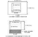
なお、入力画像の縦又は横の長さが、切り出す部分画像の縦又は横の長さに満たない場合は、入力画像の右側及び下側に画素値が一定の画像(例えば、0値の画素)を付加し、左上隅に合わせて切り出すことで部分画像とすればよい。図3は部分画像の切り出し例を示している。
Next, the processing contents of the image position specifying apparatus in FIG. 1 will be specifically described.
The
The position to cut out the partial image may be selected at random, may be selected with reference to the upper left corner, and various implementations are conceivable.
The pattern size M may be an arbitrary value, but is set to a power of 2 in a normal implementation.
The reason is that by setting the power to a power of 2, it becomes possible to perform fast Fourier transform (FFT) in the
In addition, when the vertical or horizontal length of the input image is less than the vertical or horizontal length of the partial image to be cut out, an image with a fixed pixel value (for example, a zero value pixel) on the right side and the lower side of the input image. ), And cut out in accordance with the upper left corner to form a partial image. FIG. 3 shows an example of cutting out a partial image.
フーリエ変換部2は、画像切り出し部1が部分画像を生成すると、その部分画像の画素値を2次元離散フーリエ変換し、その2次元離散フーリエ変換結果であるフーリエ係数を出力する(ステップST2)。
フーリエ係数は、M2個の複素数であり、拡大等判断部5などの各部で、その絶対値(振幅)と位相に分離して使用される。そのため、フーリエ変換部2がフーリエ係数を出力する際に、そのフーリエ係数を絶対値と位相に分離して出力してもよいし、フーリエ係数を使用する拡大等判断部5などの各部で、フーリエ係数を絶対値と位相に分離するようにしてもよい。
When the
The Fourier coefficient is a complex number of M 2 , and is used by being separated into its absolute value (amplitude) and phase by each unit such as the
ピーク検出部3は、フーリエ変換部2から周波数平面上に配置されているM2個のフーリエ係数を受けると、M2個のフーリエ係数の絶対値マップを参照して、ピーク(M2個のフーリエ係数の中で、絶対値が突出しているフーリエ係数(例えば、絶対値が最大のフーリエ係数))を検出し、そのピークの周波数平面上の座標であるピーク座標を算出する(ステップST3)。
ピークの検出処理は、公知の画像処理技術によって十分可能であるため、詳細な説明を省略する。
図4はフーリエ係数の絶対値とピーク座標の例を示す説明図である。
フーリエ係数の絶対値が、複数のフーリエ係数にまたがって突出している場合には、図4(b)に示すように、必ずしも整数値とならないピーク座標を算出するようにしてもよい。
実数値のピーク座標の計算方法は、ピークを示す座標の単純平均や、フーリエ係数の絶対値を重みとして利用する加重平均(重心計算)などがあり、様々な方法が可能である。
Peak detecting
Since the peak detection process can be sufficiently performed by a known image processing technique, detailed description thereof is omitted.
FIG. 4 is an explanatory diagram showing examples of absolute values and peak coordinates of Fourier coefficients.
When the absolute value of the Fourier coefficient protrudes across a plurality of Fourier coefficients, peak coordinates that do not necessarily become integer values may be calculated as shown in FIG.
There are various methods of calculating real-valued peak coordinates, such as a simple average of coordinates indicating a peak and a weighted average (centroid calculation) using the absolute value of a Fourier coefficient as a weight.
スペクトル対応関係算出部4は、ピーク検出部3がピーク座標を算出すると、位置合わせ信号パターンにおける周波数スペクトルの周波数平面上での座標であるスペクトル座標の中で、そのピーク座標と対応関係があるスペクトル座標を特定し、その対応関係を示すスペクトル対応情報を出力する(ステップST4)。
即ち、スペクトル対応関係算出部4は、スペクトル情報を入力して、原画像に埋め込まれているスペクトルと、部分画像から検出したスペクトルの対応関係を特定し、その対応関係を示すスペクトル対応情報を出力する。
ここで、スペクトル情報は、原画像に埋め込まれている位置合わせ信号パターンの周波数スペクトルの周波数平面上での座標(スペクトル座標)と、その周波数スペクトルの位相を意味するものである。
ただし、スペクトル対応関係算出部4が使用するのは、スペクトル情報のうち、スペクトル座標のみである。
When the
That is, the spectrum
Here, the spectrum information means the coordinates (spectrum coordinates) on the frequency plane of the frequency spectrum of the alignment signal pattern embedded in the original image and the phase of the frequency spectrum.
However, the spectrum
スペクトル対応関係算出部4は、ピーク検出部3により算出されたピーク座標が、どのスペクトル座標と対応するかを判断して、その対応関係を明らかにするものである。
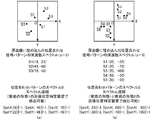
図5は周波数スペクトル及びピークとスペクトル対応情報の一例を示している。
原画像に埋め込まれた位置合わせ信号パターンの周波数スペクトルの周波数平面上での分布は必ず点対称となる。そのため、点対称(180度回転)の不確定性が残る(例えば、実装によっては、T1←→S1が対応付けられる場合がある)。
この不確定性は、後述する平行移動等判断部6で解消される。
The spectrum
FIG. 5 shows an example of frequency spectrum, peak and spectrum correspondence information.
The distribution of the frequency spectrum of the alignment signal pattern embedded in the original image is always point-symmetric. Therefore, the uncertainty of point symmetry (180 degree rotation) remains (for example, depending on the implementation, T1 ← → S1 may be associated).
This uncertainty is eliminated by a
スペクトル対応情報は、対応の取れた周波数スペクトルTkと周波数スペクトルSiの組み合わせを識別できる情報であればよい。
図5の例では、対応の取れたスペクトルは4組である。
具体的な点同士の対応付けの方法としては、対数極座標変換を用いる方法が知られている。
即ち、(X,Y)を極座標(r,θ)に変換し、かつ、r軸を対数スケールとする対数極座標(logr,θ)で各点をプロットした際に、(X,Y)平面上での拡大縮小は、(logr,θ)平面ではr軸方向への平行移動に対応し、(X,Y)平面上での回転は、(logr,θ)平面ではθ軸方向への平行移動に対応し、(X,Y)平面上での反転は、(logr,θ)平面ではr軸と平行な対称軸での反転に対応する。
この性質を利用して、公知の技術によって、周波数スペクトルTkと周波数スペクトルSiのマッチングを取ることで、対応付けを行うことができる。
The spectrum correspondence information may be information that can identify the combination of the frequency spectrum Tk and the frequency spectrum Si that can be matched.
In the example of FIG. 5, there are four sets of spectra that can be handled.
As a specific method for associating points, a method using logarithmic polar coordinate transformation is known.
That is, when (X, Y) is converted into polar coordinates (r, θ) and each point is plotted in logarithmic polar coordinates (logr, θ) with the r axis as a logarithmic scale, Enlargement / reduction at the (logr, θ) plane corresponds to translation in the r-axis direction, and rotation on the (X, Y) plane is translation in the θ-axis direction at the (logr, θ) plane. Inversion on the (X, Y) plane corresponds to inversion on an axis of symmetry parallel to the r axis in the (logr, θ) plane.
Using this property, matching can be performed by matching the frequency spectrum Tk and the frequency spectrum Si by a known technique.
ピーク検出の段階で、埋め込まれたスペクトルが検出されなかったり(見逃し)、スペクトルが埋め込まれていないのにピークとして検出されたり(誤検出)することがあるため、マッチングが2通り以上候補に挙がる可能性がある。
このような場合は、周波数スペクトルTkの位置的誤差が小さい方を選択することにより最終的な判断を行う。
また、位置的誤差を利用する方法の他に、フーリエ係数を利用する方法もある。
即ち、ピークの中でも、フーリエ係数の絶対値の大きいピークの方が、信頼性が高いと言えるので、候補に挙がったマッチングのうち、絶対値の大きいピークを含む方を選択することにより最終的な判断を行う。位置的誤差を利用する方法のようにフーリエ係数を利用せずに判断することもできるが、フーリエ係数を利用することで、マッチングの成功率を高める効果が期待される。
At the peak detection stage, the embedded spectrum may not be detected (missed), or may be detected as a peak even though the spectrum is not embedded (false detection), so there are two or more matching candidates. there is a possibility.
In such a case, the final determination is made by selecting the one with the smaller positional error of the frequency spectrum Tk.
In addition to the method using positional errors, there is also a method using Fourier coefficients.
That is, among the peaks, the peak with the larger absolute value of the Fourier coefficient can be said to be more reliable. Therefore, by selecting the one that includes the peak with the larger absolute value among the candidates listed as candidates, the final one is selected. Make a decision. Although the determination can be made without using the Fourier coefficient as in the method using the positional error, the use of the Fourier coefficient is expected to increase the success rate of matching.
拡大等判断部5は、スペクトル対応関係算出部4からスペクトル対応情報を受けると、対応関係があるピーク座標と周波数スペクトルの組み合わせから、原画像に対する入力画像の拡大縮小、回転及び反転を特定する(ステップST5)。
即ち、拡大等判断部5は、スペクトル対応情報、ピーク座標及びスペクトル情報を参照して、入力画像が、原画像に対して、どのような拡大縮小、回転、反転が施されている画像であるのかを判断する(例えば、拡大率、回転角、反転角を変えながら、入力画像を拡大縮小、回転、反転させて、どの拡大率、回転角、反転角のときに、入力画像が原画像とマッチするかを判断する)ことで、拡大縮小情報、回転情報及び反転情報を出力する。
図6はスペクトル情報の座標、ピーク座標、スペクトル対応情報、拡大縮小情報、回転情報及び反転情報の一例を示す説明図である。
ここで、拡大縮小情報は、拡大縮小の有無と、拡大縮小が有の場合には拡大率(画像の拡大率はXY平面での拡大率の逆数となる)との組み合わせからなる情報である。
回転情報は、回転の有無と、回転が有の場合には回転角(X軸正の向きからY軸正の向きへの回転とする)との組み合わせからなる情報である。
反転情報は、反転の有無と、反転が有の場合には原点から反転軸に向かう垂線の仰角(X軸正の向きを向く仰角を0とする)との組み合わせからなる情報である。
When receiving the spectrum correspondence information from the spectrum
That is, the
FIG. 6 is an explanatory diagram showing an example of coordinates, peak coordinates, spectrum correspondence information, enlargement / reduction information, rotation information, and inversion information of spectrum information.
Here, the enlargement / reduction information is information composed of a combination of the presence / absence of enlargement / reduction and the enlargement ratio (the enlargement ratio of the image is the reciprocal of the enlargement ratio on the XY plane) when enlargement / reduction is present.
The rotation information is information including a combination of presence / absence of rotation and a rotation angle (assuming rotation from the positive X-axis direction to the positive Y-axis direction) when rotation is present.
The inversion information is information composed of a combination of the presence / absence of inversion and the elevation angle of a perpendicular line from the origin to the inversion axis when the inversion is present (the elevation angle facing the positive direction of the X axis is 0).
ここでは、拡大等判断部5が、拡大縮小情報、回転情報及び反転情報を出力する例を示しているが、拡大縮小、回転、反転の内容を表すことができれば、他の情報を出力するようにしてもよい。
例えば、回転角や原点から反転軸に向かう垂線の仰角は、弧度でなくても角度でもよいし、反転情報において、原点から反転軸に向かう垂線の仰角は、垂線の仰角としてもよく、様々な表現形態が可能である。
また、拡大率は、拡大縮小無しを同時に意味するので、拡大縮小の有無というパラメータを設けない構成とすることもできる。
同様の理由で、回転有無というパラメータを設けない構成とすることもできる。
また、原点から反転軸に向かう垂線の仰角というパラメータを設けない構成も可能である。これは、例えば、原画像に対して、まず反転有なら反転を行い、その後、拡大縮小及び回転を施すというように、入力画像に至るまでに与えられる編集内容の順序を予め決めておくことによって、反転軸の角度情報は、回転角に吸収され、反転軸の角度に関する情報がなくても、あらゆる拡大縮小、回転、反転を表現することができるからである。
Here, an example is shown in which the enlargement /
For example, the elevation angle of the perpendicular line from the origin to the reversal axis may be an angle, not an arc degree, and in the reversal information, the elevation angle of the perpendicular line from the origin to the reversal axis may be the elevation angle of the perpendicular line. An expression form is possible.
Further, since the enlargement ratio means that there is no enlargement / reduction at the same time, it is possible to adopt a configuration in which a parameter for presence / absence of enlargement / reduction is not provided.
For the same reason, a configuration in which the parameter of presence / absence of rotation is not provided may be employed.
In addition, a configuration in which a parameter such as an elevation angle of a perpendicular line from the origin to the reversal axis is not provided is also possible. This is because, for example, the order of editing contents given up to the input image is determined in advance such that the original image is first inverted if it is inverted, and then scaled and rotated. This is because the angle information of the reversal axis is absorbed by the rotation angle, and any enlargement / reduction, rotation, and reversal can be expressed without information on the angle of the reversal axis.
ここでも、スペクトル対応関係算出部4と同様に、ピークの位置的誤差に起因して、ピークと対応する周波数スペクトルの組み合わせのうち、どの組み合わせから拡大率、回転角を算出するかによって、結果が異なるのが一般的である。
このときに単純平均により最終的な拡大率や回転角を算出してもよいが、フーリエ係数を活用することができる。
即ち、フーリエ係数の絶対値が大きいピークと対応する周波数スペクトルの組み合わせを優先して評価したり、重みを与えて評価したりする。単純平均を利用する方法のようにフーリエ係数を利用せずに判断することもできるが、フーリエ係数を利用することで、算出される拡大率や回転角の精度を高めることができる。
Here, as in the spectrum
At this time, the final enlargement ratio and rotation angle may be calculated by simple averaging, but Fourier coefficients can be used.
That is, the evaluation is performed with priority given to the combination of the frequency spectrum corresponding to the peak having a large absolute value of the Fourier coefficient, or by giving a weight. Although the determination can be made without using the Fourier coefficient as in the method using the simple average, the accuracy of the calculated enlargement ratio and rotation angle can be increased by using the Fourier coefficient.
平行移動等判断部6は、原画像に対する入力画像の平行移動量と、点対称移動の有無とを特定して、平行移動情報及び点対称情報を出力する。
平行移動情報は、x軸正の向き(右向き)に何ピクセル、y軸正の向き(下向き)に何ピクセル平行移動するかを表すものである。ただし、平行移動量と移動の向き(角度)で表すなど、他の表し方を使用してもよい。
点対称情報は、スペクトル対応関係算出部4で残存している点対象の不確定性を解消するため、スペクトル対応情報の通りの対応関係でよいか否か(スペクトル対応関係は真の対応関係と点対称であるか)を示す情報である。
以下、平行移動等判断部6の処理内容を具体的に説明する。
The parallel
The translation information represents how many pixels are translated in the x-axis positive direction (rightward) and how many pixels are translated in the y-axis positive direction (downward). However, other representation methods such as a translation amount and a movement direction (angle) may be used.
In order to eliminate the uncertainty of the point target remaining in the spectrum
Hereinafter, the processing content of the parallel movement etc.
平行移動等判断部6の処理順序判断部7は、スペクトル対応関係算出部4により対応関係が特定されたピーク座標と周波数スペクトルの各組み合わせに対する評価処理(平行移動量候補選択部8における評価処理)を実行するに際して、その評価処理を実行する組み合わせの順序をピーク座標におけるフーリエ係数に基づいて決定する(ステップST6)。
例えば、ピーク座標点におけるフーリエ係数の絶対値を参照し、その絶対値が大きい組み合わせから順番に、評価処理を実行する順序を決定する。
The processing
For example, the absolute value of the Fourier coefficient at the peak coordinate point is referred to, and the order in which the evaluation process is executed is determined in order from the combination having the largest absolute value.
平行移動等判断部6の平行移動量候補選択部8は、処理順序判断部7により決定された順序が先の組み合わせから順番に、当該組み合わせに係るピーク座標と周波数スペクトルを、原画像に対する入力画像の平行移動量によって評価値が変化する評価式(下記の式(1))に代入して、その評価式が成立するか否かを判別することで、入力画像の平行移動量の全候補の中から、平行移動量の絞り込みを行う(ステップST7)。
即ち、平行移動量候補選択部8は、平行移動量の全候補(x軸方向の移動ピクセル数(M通りのピクセル数)と、y軸方向の移動ピクセル数(M通りのピクセル数)の組み合わせ(全M2通り))の中から、処理順序判断部7により決定された処理順序の順番に、閾値評価をすることによって、各候補を取捨選択する処理を行う。
また、スペクトル対応情報が示す対応関係と点対称となる対応関係についても同様に、各候補を取捨選択する処理を行う。
The parallel movement amount
In other words, the parallel movement amount
Similarly, for the correspondence relationship indicated by the spectrum correspondence information and the correspondence relationship that is point-symmetric, processing for selecting each candidate is performed.
評価式: D(m,n,k)≦Th(k) (1)
ただし、
D(m,n,k)=|E(m,n,k)−EI(m,n,k)|
E(m,n,k)=mXi/M+nYi/M+(Qk−Pi)/2π
(Tkに対応するスペクトルをSiとする)
EI(m,n,k)=E(m,n,k)の最寄りの整数
Th(k)は、ピークTkについて評価する際に使用する閾値
Piは評価対象となるピークTkと対応する周波数スペクトルSiの位相
QkはTkの位相
Evaluation formula: D (m, n, k) ≦ Th (k) (1)
However,
D (m, n, k) = | E (m, n, k) −EI (m, n, k) |
E (m, n, k) = mXi / M + nYi / M + (Qk−Pi) / 2π
(Spectrum corresponding to Tk is Si)
EI (m, n, k) = E (m, n, k) nearest integer Th (k) is a threshold value Pi used for evaluating the peak Tk. Pi is a frequency spectrum corresponding to the peak Tk to be evaluated. Si phase Qk is Tk phase
平行移動量候補選択部8は、上記の評価式を満たすか否かの評価を、一度目の評価では、全てのmとnの組み合わせ(m,n)について行う。
二度目以降は、残された候補の(m,n)についてのみ行う。このようにして候補となる(m,n)を絞り込んでいくようにする。
全てのピークTkについて評価する前に候補が唯一になった場合には処理を終了する。
全てのピークTkについて評価した後で、候補が複数残されていれば、残された全ての(m,n)を可能性のある平行移動量として保持する。
点対称の不確定性の除去については、スペクトル対応情報の場合とスペクトル対応情報と点対称な場合の二通りで、平行移動量候補の絞り込みを行い、平行移動量候補の残存する方を選択することで行う。
The parallel movement amount
After the second time, only the remaining candidate (m, n) is performed. In this way, candidates (m, n) are narrowed down.
If the candidate is unique before evaluating all the peaks Tk, the process is terminated.
If a plurality of candidates are left after evaluating all the peaks Tk, all of the remaining (m, n) are held as possible parallel movement amounts.
Regarding the removal of point symmetry uncertainties, the translation correspondence candidates are narrowed down in two ways, in the case of spectrum correspondence information and in the case of point symmetry with the spectrum correspondence information, and the remaining one of the translation displacement candidates is selected. Do that.
図7は平行移動量候補選択部8による平行移動量等判断処理の概要を示す説明図である。
閾値Th(k)については、kによらない固定値であっても、図1の画像位置特定装置は動作するが、フーリエ係数の絶対値が大きいなどの理由で、信頼できるピークTkについて評価する場合には、小さな閾値Th(k)を与えるように制御することで、閾値評価による絞込み効率を高めることができる。
最終的に平行移動量候補が残らない場合は、閾値Th(k)の値を大きくし、再度、閾値評価による平行移動量候補の絞り込みを行うことで、正解の平行移動量を拾える可能性がある。それでも、なお候補が残らない場合は、失敗として処理する。
また、全ての閾値評価を終えた後で、多くの候補が残った場合は、それらの残存候補に対して、閾値Th(k)の値を小さくして、再度、閾値評価による絞込みを行うことで絞り込めばよい。また、sを十分大きく設定しておけば(図7の例では、s=3であるが、s=30などに設定する)、1候補に絞り込める確率が一段と高まり、位置特定の信頼性が高まる。
FIG. 7 is an explanatory diagram showing an outline of the parallel movement amount determination processing by the parallel movement amount
Even if the threshold Th (k) is a fixed value that does not depend on k, the image position specifying apparatus of FIG. 1 operates, but a reliable peak Tk is evaluated because the absolute value of the Fourier coefficient is large. In this case, it is possible to increase the narrowing-down efficiency by threshold evaluation by performing control so as to give a small threshold Th (k).
If no translation amount candidate finally remains, the value of the threshold Th (k) is increased, and the translation amount candidate of the correct answer may be picked up by narrowing down the translation amount candidates again by threshold evaluation. is there. If no candidate still remains, it is treated as a failure.
In addition, when many candidates remain after all threshold evaluations are completed, the threshold Th (k) is reduced for those remaining candidates and narrowed down by threshold evaluation again. You can narrow down with. Also, if s is set sufficiently large (in the example of FIG. 7, s = 3 but s = 30, etc.), the probability of narrowing down to one candidate is further increased, and the reliability of position specification is increased. Rise.
このように閾値評価を繰り返し、平行移動量の候補を絞り込んでいく方法では、平均的にO(M2)の計算量で平行移動量の判定が可能である。
以下、簡単に、その根拠を説明する。
ただし、説明の簡単化のために、閾値Th(k)をkによらず一定値Thとする。
画像に特に偏った特性がない場合は、その画像のフーリエ変換係数の位相はランダムに分布するので、閾値Thを用いた1回の閾値評価による絞り込みで、残存する平行移動量の候補を約2Th倍にできる。よって、s回絞込みを行うことで、(2Th)s倍に絞り込むことができる。
閾値評価の回数は、初回がM2回であるが、2回目はM2(2Th)回程度、3回目はM2(2Th)2回程度となり、s回目はM2(2Th)s−1回程度となる。
In this way, the threshold evaluation is repeated and the parallel movement amount candidates are narrowed down, so that it is possible to determine the parallel movement amount with an average calculation amount of O (M 2 ).
The basis for this will be briefly described below.
However, for simplicity of explanation, the threshold value Th (k) is set to a constant value Th regardless of k.
If there is no particularly biased characteristic in the image, the phase of the Fourier transform coefficient of the image is randomly distributed. Therefore, the remaining translation amount candidates are reduced to about 2 Th by narrowing down by one threshold evaluation using the threshold Th. Can be doubled. Therefore, it is possible to narrow down to (2Th) s times by narrowing down s times.
The number of threshold evaluation, but the first time is twice M, about the second time M 2 (2Th) times, the third time will be the M 2 (2Th) about two times, s round of M 2 (2Th) s-1 About once.
即ち、s個全てのスペクトルに対応するピークが検出できた場合、閾値評価回数は全部で、
M2+M2(2Th)+M2(2Th)2+・・・+M2(2Th)s−1
≦M2/(1−2Th)=O(M2)
となり、sの値にかかわらずO(M2)に抑えられる。
よって、この方法による平行移動量の特定は平均的にO(M2)の計算量となる。このため、O(M4)の計算量を必要とする相関演算を利用する平行移動量判定と比べて高速に処理することができる。
また、特許文献1に記載の方式のようにO(M2)の計算量で平行移動量判定する方式と比べても、三角関数のような複雑な演算によらず、四則演算と閾値評価で、平行移動量判定ができる点で、幾分か高速に処理することができる。
That is, when peaks corresponding to all s spectra can be detected, the threshold evaluation times are all,
M 2 + M 2 (2Th) + M 2 (2Th) 2 +... + M 2 (2Th) s−1
≦ M 2 / (1-2Th) = O (M 2 )
And is suppressed to O (M 2 ) regardless of the value of s.
Therefore, specifying the parallel movement amount by this method results in an average calculation amount of O (M 2 ). Therefore, it is possible to process at high speed as compared with the parallel movement amount determination utilizing correlation operation that requires the computation of O (M 4).
Compared with the method of determining the parallel movement amount by the calculation amount of O (M 2 ) as in the method described in
以上によって、拡大縮小情報、回転情報、反転情報、平行移動情報、点対称情報が出揃う。また、回転情報と点対称情報から正しい回転情報が得られる。
そのため、正しい拡大率(拡大縮小が有の場合)、正しい回転角(回転が有の場合)、正しい原点から反転軸に向かう垂線の仰角(反転が有の場合)、正しい平行移動量が得られる。
図1の画像位置特定装置の目的は、電子透かしデータの検出のための位置合わせであるから、通常は、図1の画像位置特定装置が、電子透かしデータ検出装置の一部として実装される。
電子透かしデータは、画像の一部しか残されていない場合であっても検出可能となるよう、通常は規則正しい繰り返しをもつ状態で埋め込まれている(図8を参照)。
As described above, enlargement / reduction information, rotation information, inversion information, parallel movement information, and point symmetry information are gathered. Also, correct rotation information can be obtained from the rotation information and point symmetry information.
Therefore, the correct enlargement ratio (when scaling is present), the correct rotation angle (when rotation is present), the vertical elevation angle from the correct origin to the reversal axis (if reversal is present), and the correct amount of translation are obtained. .
Since the object of the image position specifying device in FIG. 1 is alignment for detecting digital watermark data, the image position specifying device in FIG. 1 is usually mounted as a part of the digital watermark data detecting device.
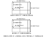
The digital watermark data is usually embedded with regular repetition (see FIG. 8) so that it can be detected even when only a part of the image remains.
図8では、位置合わせ信号パターンと同じサイズ(256ピクセル×256ピクセル)の電子透かしデータを、位置合わせ信号パターンの繰り返しに合わせて埋め込む例を示している。
このとき、電子透かしデータは、位置合わせ信号パターンに重ねて、輝度に埋め込まれていても、色差成分など他の成分に埋め込まれていてもよい。電子透かしデータの埋込方式や検出方式については本発明の範囲外であるが、繰り返し周期を合わせておきさえすれば、図1の画像位置特定装置によって得た情報で位置合わせをすることで、検出が可能になる。
FIG. 8 shows an example in which digital watermark data having the same size (256 pixels × 256 pixels) as the alignment signal pattern is embedded in accordance with the repetition of the alignment signal pattern.
At this time, the electronic watermark data may be superimposed on the alignment signal pattern and embedded in the luminance, or may be embedded in other components such as a color difference component. The digital watermark data embedding method and detection method are out of the scope of the present invention, but if the repetition period is adjusted, the registration with the information obtained by the image position specifying device of FIG. Detection is possible.
ここまでの説明では、平行移動等判断部6の平行移動量候補選択部8が、閾値評価で選別したスペクトル対応情報の通りの場合の平行移動量候補と、スペクトル対応情報と点対称な場合の平行移動量候補を比較し、残存している方を選択するとともに、どちらの候補が残存したかで、点対称の不確定性を解消するようにしている。
しかし、スペクトル対応情報の通りの場合と、スペクトル対応情報と点対称な場合で、どちらも平行移動量候補が残存する場合もある。
このような場合に、閾値Th(k)を変動させて残存候補数を調整することにより、片方の場合しか候補が残存しない結果を得るまで繰り返す方法もあるが、スコアを用いる方法もある。
In the description so far, the parallel movement amount
However, there are cases where the translation amount candidate remains in both cases according to the spectrum correspondence information and point symmetry with the spectrum correspondence information.
In such a case, there is a method in which the threshold Th (k) is varied to adjust the number of remaining candidates, and the method is repeated until a result in which only one of the candidates remains is obtained, but there is also a method using a score.
例えば、各平行移動量候補が閾値評価をクリアするとともに、評価値D(m,n,k)が閾値Th(k)に対して、どれだけ余裕があったか(例えば、Th(k)−D(m,n,k))を加算していくことでスコアをつける。
このようにスコアをつければ、最終的に残存した平行移動量候補の中で、スコアの高いものほど、閾値評価を余裕を持ってクリアしたことになり、正解の平行移動量である可能性が高いことになる。
最終的に、スペクトル対応情報の通りの場合と、スペクトル対応情報と点対称な場合の双方で残存した候補の中で、スコアの最も高いものを最終的に平行移動量として選択する方法が考えられる。この方法では、複数の平行移動量候補が残存しても閾値を再設定して閾値評価をやり直したりする必要がないため、処理が高速化されるメリットがある。
For example, each parallel movement amount candidate clears the threshold evaluation, and how much the evaluation value D (m, n, k) has a margin with respect to the threshold Th (k) (for example, Th (k) −D ( m, n, k)) is added to give a score.
If a score is given in this way, the higher the score among the finally remaining translation amount candidates, the more the threshold evaluation is cleared, and there is a possibility that it is the correct translation amount. It will be expensive.
Finally, there is a method of finally selecting the one with the highest score as the translation amount among the candidates remaining both in the case of the spectral correspondence information and in the case of point symmetry with the spectrum correspondence information. . This method has the advantage of speeding up the processing because there is no need to reset the threshold and perform threshold evaluation again even if a plurality of parallel movement amount candidates remain.
ここまでの説明では、入力画像をデジタル非圧縮輝度画像としているが、YCbCr形式やRGB形式に代表されるカラー画像であってもよい。
このような場合でも、例えば、YやRなど一つの成分を選択し、その1成分からなる画像データを非圧縮輝度画像と見立てることで、図1の画像位置特定装置を適用することができる。ただし、事前に、どの画像成分に位置合わせ信号パターンが埋め込まれているかを知っておかなければならない。
例えば、RGB形式のG成分に位置合わせ信号パターンが埋め込まれている場合には、YCbCr形式の画像の位置合わせをする際に、まず、その画像をRGB形式に変換し、その上で、G成分に対して、図1の画像位置特定装置を適用する(G成分だけからなる画像を入力画像として、図1の画像位置特定装置に与える)ことで、位置合わせが可能になる。
In the description so far, the input image is a digital uncompressed luminance image, but it may be a color image typified by a YCbCr format or an RGB format.
Even in such a case, for example, by selecting one component such as Y or R and assuming that the image data composed of the one component is an uncompressed luminance image, the image position specifying device of FIG. 1 can be applied. However, it is necessary to know in advance which image component the alignment signal pattern is embedded in.
For example, when the alignment signal pattern is embedded in the G component in the RGB format, when aligning the image in the YCbCr format, the image is first converted into the RGB format, and then the G component is converted. On the other hand, by applying the image position specifying apparatus of FIG. 1 (giving an image consisting only of the G component as an input image to the image position specifying apparatus of FIG. 1), it becomes possible to perform alignment.
また、入力画像がJPEGやGIFなど、何らかの符号化方式(圧縮方式)により符号化(圧縮)されている場合は、復号化(伸張)してから、対象となる非圧縮成分に着目して、図1の画像位置特定装置を適用すればよい。このように、図1の画像位置特定装置は、色の有無や色空間形式、画像の圧縮/非圧縮によらずに適用することができる。 In addition, when the input image is encoded (compressed) by some encoding method (compression method) such as JPEG or GIF, after decoding (expanding), pay attention to the target uncompressed component, The image position specifying device in FIG. 1 may be applied. As described above, the image position specifying apparatus of FIG. 1 can be applied regardless of the presence / absence of a color, the color space format, and compression / non-compression of an image.
ここまでの説明では、パターンサイズ(M)とスペクトル情報(s、Si、Xi、Yi、i∈[1,s])を既定として、その設定方法については特に触れていないが、通常は、方式上、固定にしておき、その固定のパラメータで位置合わせ信号パターンが埋め込まれているという前提の下で入力画像を処理する。
それ以外の実装方法として、例えば、鍵(何ビットかのデータ)を定めておき、その鍵から一意に定まるM、s、Si、Xi、Yi等のパラメータを使用して動作するように、図1の画像位置特定装置を構成することもできる。
このようにすると、位置合わせ信号パターンを埋め込む際に使用した鍵を知っている場合に限り、位置合わせが可能となる方式を実現することができる。
In the description so far, the pattern size (M) and the spectrum information (s, Si, Xi, Yi, i∈ [1, s]) are set as defaults, and the setting method thereof is not particularly mentioned. The input image is processed on the premise that the alignment signal pattern is embedded with the fixed parameters.
As another mounting method, for example, a key (data of several bits) is defined, and the operation is performed using parameters such as M, s, Si, Xi, and Yi that are uniquely determined from the key. One image position specifying device can also be configured.
In this way, it is possible to realize a method that enables alignment only when the key used for embedding the alignment signal pattern is known.
入力画像に埋め込まれている位置合わせ信号パターンを生成する鍵と異なる鍵を使用した場合には、正しくないパラメータで位置合わせを試みてしまうため、正しい結果に到達することができない。
鍵からパラメータ群(M、s、Si、Xi、Yi)への写像は、ランダム性を高めるため、ハッシュ関数を介するようにする方がよく、こうすることで、パラメータ群は予測困難となり、偶然のパラメータの一致などが期待される状況の発生を抑え、安全性を高めることができる。位置合わせができなければ、勿論、位置合わせ後の電子透かしデータの検出も失敗する。したがって、このように鍵を使用することにより、電子透かしデータの秘匿性が増すという効果が得られる。
When a key different from the key for generating the alignment signal pattern embedded in the input image is used, alignment is attempted with an incorrect parameter, so that a correct result cannot be reached.
The mapping from the key to the parameter group (M, s, Si, Xi, Yi) is preferably performed through a hash function in order to increase the randomness, which makes it difficult to predict the parameter group. Therefore, it is possible to suppress the occurrence of a situation where the matching of the parameters is expected and improve safety. If the alignment cannot be performed, of course, the detection of the digital watermark data after the alignment also fails. Therefore, by using the key in this way, the effect of increasing the confidentiality of the digital watermark data can be obtained.
ここまでの説明では、画像切り出し部1により切り出された1つの部分画像から位置合わせを行うものを示したが、画像切り出し部1が、異なる複数の部分画像を切り出し、複数の部分画像のそれぞれについて、これまで説明してきた方法によって位置合わせを行い、得られた結果を総合的に判断することで最終的な拡大縮小情報、回転情報、反転情報、平行移動情報、点対称情報を得るようにすることもできる。
このようにすると、一部の部分画像において、位置合わせ信号パターンの劣化が激しく、正確な情報が得られない場合であっても、拡大縮小有無、回転有無、反転有無、点対称情報の多数決を取ったり、拡大率、回転角、原点から反転軸に向かう垂線の仰角の平均を取ったりすることにより、各種情報の精度を高めることができる。
平行移動量については、部分画像の位置によって大きく異なる値となるが、部分画像の位置変動分を補正した上で平均を取ることで、精度を高めることができる。
In the description so far, the one that performs alignment from one partial image cut out by the
In this way, even if the alignment signal pattern is severely degraded in some partial images and accurate information cannot be obtained, the majority decision of enlargement / reduction, rotation / non-rotation, reversal / non-point symmetry information is made. The accuracy of various types of information can be improved by taking the average of the enlargement ratio, the rotation angle, and the elevation angle of the perpendicular line from the origin to the reversal axis.
The parallel movement amount varies greatly depending on the position of the partial image, but the accuracy can be improved by taking an average after correcting the position fluctuation of the partial image.
ここまでの説明では、図1の画像位置特定装置が、拡大等判断部5を実装している構成を示したが、画像位置特定装置が、拡大等判断部5を実装していない構成も可能である。
この場合、拡大縮小情報、回転情報、反転情報を得ることができないので、切取と180度回転のみに対応する画像位置特定装置となる。
In the description so far, the configuration in which the image position specifying device in FIG. 1 is mounted with the
In this case, since enlargement / reduction information, rotation information, and inversion information cannot be obtained, the image position specifying device can handle only cropping and 180-degree rotation.
ここまでの説明では、平行移動量候補選択部8が、1ピクセル刻みの粒度(Mピクセルに対して、M通りの粒度)で、平行移動量を判断するものを示したが、0.5ピクセル刻みの粒度(Mピクセルに対して、2M通りの粒度)で、平行移動量を判断したり、もっと細かい粒度で判断したり、あるいは、逆に荒い粒度で判断したりすることもできる。
特に、1ピクセル未満の粒度で判断する際に、整数精度の場合と同じ式を用いた同じアルゴリズムで判断できる点は、図1の画像位置特定装置のメリットである。なぜなら、相関演算によって平行移動量を判定する方式では、画像と位置合わせ信号パターンの小数点ピクセル差での相関演算を直ちに行えず、何らかのフィルタ演算等によって実数座標位置の画素値を算出する計算が余計に必要となるからである。
In the description so far, the parallel movement amount
In particular, when determining with a granularity of less than one pixel, it is possible to determine with the same algorithm using the same formula as in the case of integer precision, which is an advantage of the image position specifying apparatus of FIG. This is because the method of determining the parallel movement amount by the correlation calculation cannot immediately perform the correlation calculation at the decimal pixel difference between the image and the alignment signal pattern, and the calculation for calculating the pixel value at the real coordinate position by some filter calculation or the like is unnecessary. It is necessary for this.
以上で明らかなように、この実施の形態1によれば、処理順序判断部7が、スペクトル対応関係算出部4により対応関係が特定されたピーク座標と周波数スペクトルの各組み合わせに対する評価処理を実行するに際して、その評価処理を実行する組み合わせの順序をピーク座標におけるフーリエ係数に基づいて決定し、平行移動量候補選択部8が、処理順序判断部7により決定された順序が先の組み合わせから順番に、当該組み合わせに係るピーク座標と周波数スペクトルを、原画像に対する入力画像の平行移動量によって評価値が変化する評価式に代入して、その評価式が成立するか否かを判別することで、入力画像の平行移動量の全候補の中から、平行移動量の絞り込みを行うように構成したので、切取の編集に伴う位置合わせの高速化を図ることができる効果を奏する。
As is apparent from the above, according to the first embodiment, the processing
実施の形態2.
上記実施の形態1では、平行移動量候補選択部8が、X軸及びY軸における平行移動量m,nを同時に絞り込むものを示したが、平行移動量候補選択部8が、X軸における平行移動量mの絞り込みと、Y軸における平行移動量nの絞り込みを別々に行うことで、更なる処理の高速化を図るようにしてもよい。
画像位置特定装置の構成図及びフローチャートは、上記実施の形態1と同じである。
図9は平行移動量候補選択部8による平行移動量等判断処理の概要を示す説明図である。
In the first embodiment, the parallel movement amount
The configuration diagram and flowchart of the image position specifying device are the same as those in the first embodiment.
FIG. 9 is an explanatory diagram showing an outline of the parallel movement amount determination processing by the parallel movement amount
上記実施の形態1と比較して、画像切り出し部1、フーリエ変換部2、ピーク検出部3、スペクトル対応関係算出部4及び拡大等判断部5の処理内容は同様であるが、平行移動等判断部6の処理内容が相違している。
即ち、上記実施の形態1では、ピークTkに対応する周波数スペクトルをSiとし、Siの位相をPi(Si=|Si|exp(jPi))、Tkの位相をQk(Tk=|Tk|exp(jQk))とするとき、
E(m,n,k)=mXi/M+nYi/M+(Qk−Pi)/2π≒整数
(対応するSiとTkの任意の組み合わせ)
が成り立つmとnを選択するようにしている。
Compared with the first embodiment, the
That is, in the first embodiment, the frequency spectrum corresponding to the peak Tk is Si, the phase of Si is Pi (Si = | Si | exp (jPi)), and the phase of Tk is Qk (Tk = | Tk | exp ( jQk)),
E (m, n, k) = mXi / M + nYi / M + (Qk−Pi) / 2π≈integer (any combination of corresponding Si and Tk)
M and n satisfying the above are selected.
これに対して、この実施の形態2では、ピークTkに対応する周波数スペクトルをSiとし、Siの位相をPi(Si=|Si|exp(jPi))、Tkの位相をQk(Tk=|Tk|exp(jQk))、Tqに対応する周波数スペクトルをSpとし、Spの位相をPp(Sp=|Sp|exp(jPp))、Tqの位相をQq(Tq=|Tq|exp(jQq))、i,p∈SetX(X)={i|Xi=X,i∈[1,s]}、i≠pとするとき、
Hy(n,k,q)=n(Yi−Yp)/M+(Qk−Pi−Qq+Pp)/2π
≒整数(対応するSiとTk、SpとTqの任意の組み合わせ)
が成り立つnを選択するようにしている。
また、i,p∈SetY(Y)={i|Yi=Y,i∈[1,s]}、i≠pとするとき、
Hx(m,k,q)=m(Xi−Xp)/M+(Qk−Pi−Qq+Pp)/2π
≒整数(対応するSiとTk、SpとTqの任意の組み合わせ)
が成り立つmを選択するようにしている。
これにより、平行移動量が明らかとなり、入力画像と原画像の位置合わせが完了する。
On the other hand, in the second embodiment, the frequency spectrum corresponding to the peak Tk is Si, the phase of Si is Pi (Si = | Si | exp (jPi)), and the phase of Tk is Qk (Tk = | Tk). | Exp (jQk)), the frequency spectrum corresponding to Tq is Sp, the phase of Sp is Pp (Sp = | Sp | exp (jPp)), and the phase of Tq is Qq (Tq = | Tq | exp (jQq)) , I, pεSetX (X) = {i | Xi = X, iε [1, s]}, i ≠ p,
Hy (n, k, q) = n (Yi−Yp) / M + (Qk−Pi−Qq + Pp) / 2π
≒ integer (any combination of corresponding Si and Tk, Sp and Tq)
N that satisfies is selected.
When i, pεSetY (Y) = {i | Yi = Y, iε [1, s]}, i ≠ p,
Hx (m, k, q) = m (Xi−Xp) / M + (Qk−Pi−Qq + Pp) / 2π
≒ integer (any combination of corresponding Si and Tk, Sp and Tq)
M that satisfies is selected.
Thereby, the amount of parallel movement becomes clear, and the alignment of the input image and the original image is completed.
以下、この実施の形態2における平行移動等判断部6の処理順序判断部7及び平行移動量候補選択部8の処理内容を具体的に説明する。
処理順序判断部7は、上記実施の形態1と同様に、スペクトル対応関係算出部4により対応関係が特定されたピーク座標と周波数スペクトルの各組み合わせに対する評価処理(平行移動量候補選択部8における評価処理)を実行するに際して、その評価処理を実行する組み合わせの順序をピーク座標におけるフーリエ係数に基づいて決定する。
ただし、処理順序判断部7は、上記実施の形態1と異なり、一度の評価処理に用いるピーク座標と周波数スペクトルの組み合わせが2つずつであるため、2つずつの組み合わせの順序を決定する。
例えば、ピーク点におけるフーリエ係数の絶対値が最大である組み合わせと、その他のピーク点との組み合わせについて、絶対値が最大でない方のピーク点は、フーリエ係数の絶対値が大きいものから順に組み合わせるものとする。
Hereinafter, the processing contents of the processing
Similar to the first embodiment, the processing
However, unlike the first embodiment, the processing
For example, for the combination of the maximum absolute value of the Fourier coefficient at the peak point and the combination with other peak points, the peak point with the absolute value that is not maximum is combined in order from the largest absolute value of the Fourier coefficient. To do.
x軸方向の位置合わせには、T1(S1に対応)、T2(S2に対応)、T3(S2の共役複素数に対応)、T4(S3に対応)又はT8(S3の共役複素数に対応)を使用することができる。このうち、フーリエ係数の絶対値が最も高いのは、T2である。したがって、T2と他のピークとの組み合わせを使用する。
T1とT4では、フーリエ係数の絶対値が同じである。よって、どの順序でもよい。
例えば、x軸方向の位置合わせは(T2, T1)、(T2, T4)の順で行えばよい。一方、y軸方向の位置合わせには、T1(S1に対応)、T6(S5に対応)、T7(S4に対応)を使用することができる。このうち、フーリエ係数の絶対値が最も高いのは、T7である。したがって、T7と他のピークとの組み合わせを使用する。
T1とT6では、フーリエ係数の絶対値はT6の方が大きい。よって、y軸方向の位置合わせは(T7, T6)、(T7, T1)の順で行う。
For alignment in the x-axis direction, T1 (corresponding to S1), T2 (corresponding to S2), T3 (corresponding to the conjugate complex number of S2), T4 (corresponding to S3) or T8 (corresponding to the conjugate complex number of S3) is used. Can be used. Among these, T2 has the highest absolute value of the Fourier coefficient. Therefore, a combination of T2 and other peaks is used.
In T1 and T4, the absolute value of the Fourier coefficient is the same. Thus, any order is acceptable.
For example, the alignment in the x-axis direction may be performed in the order of (T2, T1) and (T2, T4). On the other hand, T1 (corresponding to S1), T6 (corresponding to S5), and T7 (corresponding to S4) can be used for alignment in the y-axis direction. Among these, T7 has the highest absolute value of the Fourier coefficient. Therefore, a combination of T7 and other peaks is used.
In T1 and T6, the absolute value of the Fourier coefficient is larger in T6. Therefore, alignment in the y-axis direction is performed in the order of (T7, T6) and (T7, T1).
平行移動量候補選択部8は、x軸方向とy軸方向の平行移動量の全候補、即ち、x軸方向の移動ピクセル数(M通りのピクセル数)と、y軸方向の移動ピクセル数(M通りのピクセル数)の中から、処理順序判断部7により決定された処理順序の順番に、閾値評価をすることによって、x軸方向の各候補の取捨選択と、y軸方向の各候補の取捨選択とを別々に行う。
また、スペクトル対応情報が示す対応関係と点対称となる対応関係についても同様に、x軸方向の各候補の取捨選択と、y軸方向の各候補の取捨選択とを別々に行う。
The parallel movement amount
Similarly, with respect to the correspondence relationship indicated by the spectrum correspondence information and the point-symmetric correspondence relationship, selection of each candidate in the x-axis direction and selection of each candidate in the y-axis direction are performed separately.
具体的には、平行移動量候補選択部8が、下記の式(2)の評価式が成立するか否かを判別することで、x軸方向の各候補の取捨選択を行い、下記の式(3)の評価式が成立するか否かを判別することで、y軸方向の各候補の取捨選択を行う。
Specifically, the parallel movement amount
評価式: Dx(m,k,q)≦Thx(k,q) (2)
ただし、
Dx(m,k,q)=|Hx(m,k,q)−HxI(m,k,q)|
Hx(m,k,q)=E(m,n,k)−G(m,n,q)
=m(Xi−Xp)/M+(Qk−Pi−Qq+Pp)/2π
(Yi=Yp, i∈SetY(Yi), p∈SetY(Yi))
E(m,n,k)=mXi/M+nYi/M+(Qk−Pi)/2π
(Tkに対応するスペクトルをSiとする)
G(m,n,q)=mXp/M+nYp/M+(Qq−Pp)/2π
(Tqに対応するスペクトルをSpとする)
HxI(m,k,q)=Hx(m,k,q)の最寄りの整数
Evaluation formula: Dx (m, k, q) ≦ Thx (k, q) (2)
However,
Dx (m, k, q) = | Hx (m, k, q) −HxI (m, k, q) |
Hx (m, k, q) = E (m, n, k) −G (m, n, q)
= M (Xi−Xp) / M + (Qk−Pi−Qq + Pp) / 2π
(Yi = Yp, iεSetY (Yi), pεSetY (Yi))
E (m, n, k) = mXi / M + nYi / M + (Qk−Pi) / 2π
(Spectrum corresponding to Tk is Si)
G (m, n, q) = mXp / M + nYp / M + (Qq−Pp) / 2π
(Spectrum Sp corresponding to Tq)
HxI (m, k, q) = nearest integer of Hx (m, k, q)
評価式: Dy(n,k,q)≦Thy(k,q) (3)
ただし、
Dy(n,k,q)=|Hy(n,k,q)−HyI(n,k,q)|
Hy(n,k,q)=E(m,n,k)−G(m,n,q)
=n(Yi−Yp)/M+(Qk−Pi−Qq+Pp)/2π
(Xi=Xp, i∈SetX(Xi), p∈SetX(Xi))
HyI(n,k,q)=Hy(n,k,q)の最寄りの整数
Evaluation formula: Dy (n, k, q) ≦ Thy (k, q) (3)
However,
Dy (n, k, q) = | Hy (n, k, q) −HyI (n, k, q) |
Hy (n, k, q) = E (m, n, k) −G (m, n, q)
= N (Yi−Yp) / M + (Qk−Pi−Qq + Pp) / 2π
(Xi = Xp, iεSetX (Xi), pεSetX (Xi))
HyI (n, k, q) = nearest integer of Hy (n, k, q)
ここで、Thx(k,q)及びThy(k,q)は、それぞれx軸方向及びy軸方向の平行移動量を絞り込む際に、TkとTqの組み合わせの評価に用いる閾値である。
式(2)の評価式を満たすか否かの評価を、x軸方向の平行移動量について行う場合、一度目の評価では全てのmについて行い、二度目以降は残されたmについてのみ行う。
式(3)の評価式を満たすか否かの評価を、y軸方向の平行移動量について行う場合、一度目の評価では全てのnについて行い、二度目以降は残されたnについてのみ行う。
このようにして候補となるmとnを別々に絞り込んでいくようにする。
全てのTkとTqの組み合わせについて評価する前に候補が唯一になった場合は処理を終了する。
全てのTkについて評価した後で、候補が複数残されていれば、残された全てのmやnを可能性のある平行移動量として保持する。
点対称の不確定性の除去については、スペクトル対応情報の場合とスペクトル対応情報と点対称な場合の二通りで、平行移動量候補の絞り込みを行い、平行移動量候補の残存する方を選択することで行う。
Here, Thx (k, q) and Thy (k, q) are threshold values used for evaluating the combination of Tk and Tq when narrowing the parallel movement amounts in the x-axis direction and the y-axis direction, respectively.
When evaluating whether or not the evaluation formula of Expression (2) is satisfied with respect to the parallel movement amount in the x-axis direction, the first evaluation is performed for all m, and the second and subsequent tests are performed only for the remaining m.
When evaluating whether or not the evaluation formula (3) is satisfied with respect to the amount of translation in the y-axis direction, the first evaluation is performed for all n, and the second and subsequent tests are performed only for the remaining n.
In this way, candidate m and n are narrowed down separately.
If the candidate is unique before evaluating all combinations of Tk and Tq, the process is terminated.
If a plurality of candidates are left after evaluating all Tk, all the remaining m and n are held as possible parallel movement amounts.
Regarding the removal of point symmetry uncertainties, the translation correspondence candidates are narrowed down in two ways, in the case of spectrum correspondence information and in the case of point symmetry with the spectrum correspondence information, and the remaining one of the translation displacement candidates is selected. Do that.
このように閾値評価を繰り返し、平行移動量の候補を絞り込んでいく方法では、平均的にO(M)の計算量で平行移動量の判定が可能である。
以下、簡単に、その根拠を説明する。
ただし、説明の簡単化のために、閾値Thx(k,q)や閾値Thy(k,q)をkによらず一定値Thとする。
画像に特に偏った特性がない場合は、その画像のフーリエ変換係数の位相はランダムに分布するので、閾値Thを用いた1回の閾値評価による絞り込みで、残存する平行移動量の候補を約2Th倍にできる。よって、x軸方向でもy軸方向でも、検討すべき平行移動量はMなので、この絞込みを繰り返していくと、この閾値評価回数は全部で、
M+M(2Th)+M(2Th)2+・・・≦M/(1−2Th)=O(M)
となり、sの値にかかわらずO(M)に抑えられる。
この実施の形態2では、x軸方向とy軸方向について別々に行うが、単に評価回数は2倍になるだけであり、計算量がO(M)であることに変わりはない。このため、上記実施の形態1よりも、高速に平行移動量の判定を行うことができる。
In this way, the threshold value evaluation is repeated and the parallel movement amount candidates are narrowed down, so that it is possible to determine the parallel movement amount with an average calculation amount of O (M).
The basis for this will be briefly described below.
However, for simplicity of explanation, the threshold value Thx (k, q) and the threshold value Thy (k, q) are set to a constant value Th regardless of k.
If there is no particularly biased characteristic in the image, the phase of the Fourier transform coefficient of the image is randomly distributed. Therefore, the remaining translation amount candidates are reduced to about 2 Th by narrowing down by one threshold evaluation using the threshold Th. Can be doubled. Therefore, since the amount of parallel movement to be examined is M in both the x-axis direction and the y-axis direction, when this narrowing is repeated, the number of threshold evaluations is
M + M (2Th) + M (2Th) 2 +... ≦ M / (1-2Th) = O (M)
Thus, O (M) is suppressed regardless of the value of s.
In the second embodiment, the x-axis direction and the y-axis direction are separately performed. However, the number of evaluations is merely doubled, and the calculation amount is still O (M). For this reason, it is possible to determine the amount of parallel movement faster than in the first embodiment.
ここまでの説明では、ピーク検出部3が、上記実施の形態1と同様に動作をするものとしているが、図12(b)のように、同一直線上に複数の周波数スペクトル座標が存在するように位置合わせ信号パターンが設定されている入力画像を扱うことが前提である。
よって、上記実施の形態1のピーク検出部3により検出されたピークをそのまま使用するのではなく、検出された複数のピークからの距離が小さくなるような直線(例えば、複数のピークから求まる回帰直線)に向けて引いた、それらピークの垂線と直線の交点(垂点)をピークとするピーク座標を生成する方法もある。このようにすることで、直線上からずれて検出されたピークを直線上へ補正する効果が期待され、ピーク座標の精度を高めることができる。
In the description so far, the
Therefore, instead of using the peak detected by the
実施の形態3.
図10はこの発明の実施の形態3による位置合わせ信号埋込装置を示す構成図である。
図10において、逆フーリエ変換部11はスペクトル情報を逆フーリエ変換して、入力されたパターンサイズの位置合わせ信号パターンを生成する処理を実施する。
逆フーリエ変換部11により逆フーリエ変換されるスペクトル情報が示すs個の周波数スペクトルSi(i∈[1,s])の中には、図12(b)に示すように、X座標又はY座標を同じくする関係がある複数の周波数スペクトルが含まれていることがある(例えば、周波数スペクトルS1,S2,S3はX座標が同じであり、周波数スペクトルS1,S4,S5はY座標が同じである)。
なお、逆フーリエ変換部11は位置合わせ信号パターン生成手段を構成している。
強度調整部12は原画像の画像的特徴に応じて、逆フーリエ変換部11により生成された位置合わせ信号パターンの強度を調整する処理を実施する。なお、強度調整部12は強度調整手段を構成している。
埋込部13は強度調整部12により強度が調整された位置合わせ信号パターンを原画像に埋め込む処理を実施する。なお、埋込部13は位置合わせ信号パターン埋込手段を構成している。
FIG. 10 is a block diagram showing an alignment signal embedding device according to
In FIG. 10, an inverse
In the s frequency spectra Si (i∈ [1, s]) indicated by the spectrum information subjected to inverse Fourier transform by the inverse
The inverse
The
The embedding
図10の例では、位置合わせ信号埋込装置の構成要素である逆フーリエ変換部11、強度調整部12及び埋込部13のそれぞれが専用のハードウェア(例えば、CPUを実装している半導体集積回路、あるいは、ワンチップマイコンなど)で構成されているものを想定しているが、位置合わせ信号埋込装置がコンピュータなどで構成される場合には、逆フーリエ変換部11、強度調整部12及び埋込部13の処理内容を記述しているプログラムの全部又は一部をコンピュータのメモリに格納し、当該コンピュータのCPUが当該メモリに格納されているプログラムを実行するようにしてもよい。
図11はこの発明の実施の形態1による位置合わせ信号埋込装置の処理内容(位置合わせ信号埋込方法)を示すフローチャートである。
In the example of FIG. 10, each of the inverse
FIG. 11 is a flowchart showing the processing contents (alignment signal embedding method) of the alignment signal embedding apparatus according to
次に動作について説明する。
この実施の形態3では、図1の画像位置特定装置が位置合わせを行うことができる位置合わせ信号パターン埋め込み済みのデジタル画像を生成する位置合わせ信号埋込装置について説明する。
Next, the operation will be described.
In the third embodiment, an alignment signal embedding device that generates a digital image in which an alignment signal pattern has been embedded, which can be aligned by the image position specifying device of FIG. 1, will be described.
逆フーリエ変換部11は、スペクトル情報とパターンサイズを入力すると、そのスペクトル情報を逆フーリエ変換して、そのパターンサイズの位置合わせ信号パターンを生成する(図11のステップST11)。
ここで、スペクトル情報は、位置合わせ信号パターンにおける周波数スペクトルの周波数平面上での座標と位相である。
逆フーリエ変換部11が逆フーリエ変換を行うには、スペクトル絶対値(振幅)も必要であるが、全てのスペクトルについて固定の絶対値を用いればよいので、特に指定する必要はない。
When the inverse
Here, the spectrum information is the coordinates and phase on the frequency plane of the frequency spectrum in the alignment signal pattern.
In order for the inverse
スペクトル情報が、s個の周波数スペクトルSi(i∈[1,s])について、周波数スペクトルSiの周波数平面上での位置が(Xi,Yi)(Xi∈[1,M/2−1])であり、周波数スペクトルSiの位相がPi(Si=|Si|exp(jPi))であることを表しており、パターンサイズがMである場合、位置合わせ信号パターンのフーリエ変換F(X,Y)(X∈[−M/2,M/2−1],Y∈[−M/2,M/2−1])は、下記のようになる。
F(X,Y)=Si=exp(jPi)
((X,Y)∈{(Xi,Yi)|i∈[1,s]})
Siの共役複素数((X,Y)∈{(−Xi,−Yi)|i∈[1,s]})
0(その他の(X,Y))
The spectrum information is s frequency spectra Si (i∈ [1, s]), and the position of the frequency spectrum Si on the frequency plane is (Xi, Yi) (Xi∈ [1, M / 2-1]). And the phase of the frequency spectrum Si is Pi (Si = | Si | exp (jPi)), and when the pattern size is M, the Fourier transform F (X, Y) of the alignment signal pattern (X∈ [−M / 2, M / 2-1], Y∈ [−M / 2, M / 2-1]) is as follows.
F (X, Y) = Si = exp (jPi)
((X, Y) ε {(Xi, Yi) | iε [1, s]})
Conjugated complex number of Si ((X, Y) ∈ {(− Xi, −Yi) | i∈ [1, s]})
0 (other (X, Y))
ここでは、周波数スペクトルSiの絶対値を1で統一しているが、他の値でもよい。これをフーリエ逆変換することで、位置合わせ信号パターンが得られるので、位置合わせ信号パターンf(x,y)(x∈[−M/2,M/2−1],y∈[−M/2,M/2−1])は、下記のようになる。
f(x,y)
=(1/M)Σ(X,Y)F(X,Y)exp(j2πxX/M)exp(j2πyY/M)
Here, the absolute value of the frequency spectrum Si is unified with 1, but other values may be used. Since an alignment signal pattern is obtained by performing inverse Fourier transform on this, the alignment signal pattern f (x, y) (x∈ [−M / 2, M / 2-1], y∈ [−M / 2, M / 2-1]) is as follows.
f (x, y)
= (1 / M) Σ (X, Y) F (X, Y) exp (j2πxX / M) exp (j2πyY / M)
強度調整部12は、逆フーリエ変換部11が位置合わせ信号パターンを生成すると、原画像の画像的特徴に応じて、その位置合わせ信号パターンの強度を調整し、強度調整後の位置合わせ信号パターンを埋込パターンとして出力する(ステップST12)。
原画像をImage(x,y)(x∈[0,W−1],y∈[0,H−1])とし、画素(x,y)に対する埋込強度をintensity(x,y)とすると、埋込パターンemb(x,y)(x∈[0,W−1],y∈[0,H−1])は、下記のようになる。
emb(x,y)
=truncate{intensity(x,y)
×f(((x+M/2)mod M)−M/2,((y+M/2)mod M)−M/2)
/max(x',y')|f(x’,y’)|}
ただし、truncate(z)は、例えば、四捨五入によって、zに最も近い整数を返す関数である。
When the inverse
The original image is Image (x, y) (x∈ [0, W−1], y∈ [0, H−1]), and the embedding strength for the pixel (x, y) is intensity (x, y). Then, the embedding pattern emb (x, y) (x∈ [0, W−1], y∈ [0, H−1]) is as follows.
emb (x, y)
= Truncate {intensity (x, y)
Xf (((x + M / 2) mod M) -M / 2, ((y + M / 2) mod M) -M / 2)
/ Max (x ′, y ′) | f (x ′, y ′) |}
However, truncate (z) is a function that returns an integer closest to z by rounding off, for example.
上式では、埋込パターンf(x,y)を埋込パターンの絶対値の最大値が1となるように実数倍することで正規化し、その上で、強度を掛け合わせている。
これにより、画素(x,y)に対して、適切な強度intensity(x,y)に調整された埋込パターンemb(x,y)を生成することができる。
また、位置合わせ信号パターンは、Mピクセル長の正方形であるが、これを循環的に原画像に対して適用することで、任意サイズの原画像image(x,y)に対して、埋込パターンemb(x,y)を生成することができる。
Intensity(x,y)は、通常、x、y及びimageの関数であり、原画像imageの画像的特徴が画質劣化に対して許容度が大きいと判断する場合に大きな値、そうでない場合に小さな値や0となる。このように強度を調整することによって、主観画質の劣化を抑制する効果と、埋込量を増やすことによる位置合わせ時の精度向上の効果の両立を図ることができる。
In the above equation, the embedding pattern f (x, y) is normalized by multiplying it by a real number so that the maximum absolute value of the embedding pattern becomes 1, and then the intensity is multiplied.
Thereby, the embedding pattern emb (x, y) adjusted to an appropriate intensity intensity (x, y) can be generated for the pixel (x, y).
The alignment signal pattern is a square having an M pixel length. By applying this to the original image cyclically, the embedding pattern can be applied to the original image image (x, y) of any size. emb (x, y) can be generated.
Intensity (x, y) is usually a function of x, y and image, a large value when judging that the image features of the original image image have a high tolerance for image quality degradation, and a small value otherwise. Value or 0. By adjusting the strength in this way, it is possible to achieve both the effect of suppressing the deterioration of the subjective image quality and the effect of improving the accuracy at the time of alignment by increasing the embedding amount.
埋込部13は、強度調整部12から埋込パターンを受けると、その埋込パターンを原画像に埋め込む処理を実施する(ステップST13)。
埋込パターンの埋込は、通常、単純な足し算である。ただし、足し算の結果が画素値の範囲を超える場合には、範囲内に切り詰める処理が加わる。
切り詰め処理は、加算の後で行ってもよいし、加算前に、原画像の全画素値に対して、max(x,y)intensity(x,y)の強度で埋め込まれても、切り詰めの必要がないように事前に行っておいてもよい。
When receiving the embedding pattern from the
Embedding the embedding pattern is usually a simple addition. However, when the result of the addition exceeds the range of the pixel value, a process of truncating within the range is added.
The truncation process may be performed after the addition, or before the addition, the truncation process may be performed by embedding all pixel values of the original image with the intensity of max (x, y) intensity (x, y). It may be done in advance so that it is not necessary.
これまでの説明では、周波数スペクトルSiの座標(Xi,Yi)について、特に規制を課していないが、周波数スペクトルSiの座標(Xi,Yi)の間に、特定の関係が成り立つように、座標(Xi,Yi)を調整することで、位置合わせ時における処理の高速化が可能になる。
ここで、高速処理が可能となる座標(Xi,Yi)の関係とは、集合SetX及びSetYを下記のように定義したときに、maxX|SetX(X)|及びmaxY|SetY(Y)|が大きな値を取るようにすることである。
SetX(X)={i|Xi=X,i∈[1,s]}
SetY(Y)={i|Yi=Y,i∈[1,s]}
In the description so far, no particular restriction is imposed on the coordinates (Xi, Yi) of the frequency spectrum Si, but the coordinates are set so that a specific relationship is established between the coordinates (Xi, Yi) of the frequency spectrum Si. By adjusting (Xi, Yi), it is possible to increase the processing speed during alignment.
Here, the relationship between the coordinates (Xi, Yi) enabling high-speed processing is as follows. When the sets SetX and SetY are defined as follows, max X | SetX (X) | and max Y | SetY (Y) Is to take a large value.
SetX (X) = {i | Xi = X, i∈ [1, s]}
SetY (Y) = {i | Yi = Y, i∈ [1, s]}
図12は、このような関係を満たさない場合(a)と、満たす場合(b)の例を示している。
図12(b)のように、スペクトル座標を設定することにより、上記実施の形態2の画像位置特定装置で処理することが可能となる。
上記実施の形態1の画像位置特定装置による位置合わせでは、平行移動等判断部6で平均的にO(M2)の計算量が必要となるのに対して、上記実施の形態2の画像位置特定装置による位置合わせでは、平行移動等判断部6で平均的にO(M)の計算量で処理することができる。
FIG. 12 shows an example of a case where such a relationship is not satisfied (a) and a case where the relationship is satisfied (b).
As shown in FIG. 12B, by setting the spectral coordinates, the image position specifying device of the second embodiment can be processed.
In the alignment by the image position specifying device according to the first embodiment, the amount of calculation of O (M 2 ) is required on the average by the parallel
これまでの説明では、周波数スペクトルを逆フーリエ変換して位置合わせ信号パターンを生成してから、画像上での加算によって原画像に埋込パターンを埋め込むものを示したが、フーリエ変換の線形性から明らかなように、原画像をフーリエ変換し、そこに周波数平面上で周波数スペクトルを加算してから、逆フーリエ変換によって出力画像を得ることもできる。ただし、強度調整を画像位置に応じて行うことができる点で、この実施の形態3の構成が優れている。 In the description so far, the frequency spectrum is subjected to inverse Fourier transform to generate an alignment signal pattern, and then the embedding pattern is embedded in the original image by addition on the image. As is apparent, an output image can be obtained by performing an inverse Fourier transform after Fourier transforming the original image and adding a frequency spectrum to the original image. However, the configuration of the third embodiment is excellent in that the intensity adjustment can be performed according to the image position.
これまでの説明では、図10の位置合わせ信号埋込装置が、強度調整部12を実装しているものを示したが、強度調整部12を設けない構成とすることもできる。
この場合は、位置合わせ信号パターンが、そのまま埋込パターンとなる。
また、適切な強度を事前に調整しておく必要があるため(例えば、画素値が0から255の値を取る場合、強度を1や2などに事前に調整しておく必要がある)、逆フーリエ変換部11が、位置合わせ信号パターンを出力する段階で、位置合わせ信号パターンの絶対値の最大値や平均値が設定された強度となるように実数倍する処理を加えるなどしておく必要がある。
In the description so far, the alignment signal embedding device of FIG. 10 has been shown in which the
In this case, the alignment signal pattern becomes an embedded pattern as it is.
Moreover, since it is necessary to adjust an appropriate intensity in advance (for example, when the pixel value takes a value from 0 to 255, the intensity needs to be adjusted in advance to 1 or 2), the reverse When the
これまでの説明では、同時に埋め込まれる電子透かしデータを検出する際の位置合わせを可能にすることが主目的である。そのため、多くの場合は、図10の位置合わせ信号埋込装置が、電子透かしデータの埋込装置と併せて使用されるか、電子透かしデータ埋込装置の一部に組み込まれる。
その際、画像の一部が切取で失われても電子透かしデータが検出できるように、通常、電子透かしデータは繰り返し同じ埋込を適用する形で埋め込まれる。
図8は位置合わせ信号パターンの繰り返しと電子透かしデータの繰り返しを合わせている例であり、図1の画像位置特定装置によって位置合わせができれば、電子透かしデータを検出することが可能になる。
In the description so far, the main purpose is to enable alignment when detecting digital watermark data embedded at the same time. Therefore, in many cases, the alignment signal embedding device shown in FIG. 10 is used together with the digital watermark data embedding device or is incorporated into a part of the digital watermark data embedding device.
At that time, the digital watermark data is normally embedded in such a manner that the same embedding is repeatedly applied so that the digital watermark data can be detected even if a part of the image is lost due to clipping.
FIG. 8 shows an example in which the repetition of the alignment signal pattern and the repetition of the digital watermark data are combined. If the alignment can be performed by the image position specifying device of FIG. 1, the digital watermark data can be detected.
これまでの説明では、位置合わせ信号パターンf(x,y)から埋込パターンemb(x,y)を生成する際に、位置合わせ信号パターンの左上を原画像の左上に合わせて、循環適用しているが、必ずしも左上を合わせる必要はない。ただし、位置合わせ信号パターンと同時に埋め込まれる電子透かしデータを検出できるようにすることが目的であるため、位置合わせ信号パターンと電子透かしデータは位置的に同期していなければならない。 In the above description, when the embedding pattern emb (x, y) is generated from the alignment signal pattern f (x, y), the upper left of the alignment signal pattern is aligned with the upper left of the original image, and is cyclically applied. However, it is not always necessary to match the upper left. However, since the purpose is to enable detection of digital watermark data embedded simultaneously with the alignment signal pattern, the alignment signal pattern and the electronic watermark data must be synchronized in position.
なお、本願発明はその発明の範囲内において、各実施の形態の自由な組み合わせ、あるいは各実施の形態の任意の構成要素の変形、もしくは各実施の形態において任意の構成要素の省略が可能である。 In the present invention, within the scope of the invention, any combination of the embodiments, or any modification of any component in each embodiment, or omission of any component in each embodiment is possible. .
1 画像切り出し部(部分画像生成手段)、2 フーリエ変換部(フーリエ変換手段)、3 ピーク検出部(ピーク座標特定手段)、4 スペクトル対応関係算出部(対応関係特定手段)、5 拡大等判断部(拡大等特定手段)、6 平行移動等判断部、7 処理順序判断部(評価順序決定手段)、8 平行移動量候補選択部(平行移動量特定手段)、11 逆フーリエ変換部(位置合わせ信号パターン生成手段)、12 強度調整部(強度調整手段)、13 埋込部(位置合わせ信号パターン埋込手段)。
DESCRIPTION OF
Claims (10)
位置合わせ信号パターン埋込手段は、上記強度調整手段により強度が調整された位置合わせ信号パターンを原画像に埋め込むことを特徴とする請求項6または請求項7記載の位置合わせ信号埋込装置。 In accordance with the image characteristics of the original image, provided is an intensity adjustment means for adjusting the intensity of the alignment signal pattern generated by the alignment signal pattern generation means,
8. The alignment signal embedding apparatus according to claim 6, wherein the alignment signal pattern embedding unit embeds the alignment signal pattern whose intensity is adjusted by the intensity adjusting unit in an original image.
Priority Applications (1)
| Application Number | Priority Date | Filing Date | Title |
|---|---|---|---|
| JP2011003068A JP2012147180A (en) | 2011-01-11 | 2011-01-11 | Device and method for identifying image position, and device and method for embedding alignment signal |
Applications Claiming Priority (1)
| Application Number | Priority Date | Filing Date | Title |
|---|---|---|---|
| JP2011003068A JP2012147180A (en) | 2011-01-11 | 2011-01-11 | Device and method for identifying image position, and device and method for embedding alignment signal |
Publications (1)
| Publication Number | Publication Date |
|---|---|
| JP2012147180A true JP2012147180A (en) | 2012-08-02 |
Family
ID=46790314
Family Applications (1)
| Application Number | Title | Priority Date | Filing Date |
|---|---|---|---|
| JP2011003068A Pending JP2012147180A (en) | 2011-01-11 | 2011-01-11 | Device and method for identifying image position, and device and method for embedding alignment signal |
Country Status (1)
| Country | Link |
|---|---|
| JP (1) | JP2012147180A (en) |
Cited By (1)
| Publication number | Priority date | Publication date | Assignee | Title |
|---|---|---|---|---|
| JP2016514868A (en) * | 2013-03-18 | 2016-05-23 | ゼネラル・エレクトリック・カンパニイ | Image quality evaluation of microscopic images |
-
2011
- 2011-01-11 JP JP2011003068A patent/JP2012147180A/en active Pending
Cited By (1)
| Publication number | Priority date | Publication date | Assignee | Title |
|---|---|---|---|---|
| JP2016514868A (en) * | 2013-03-18 | 2016-05-23 | ゼネラル・エレクトリック・カンパニイ | Image quality evaluation of microscopic images |
Similar Documents
| Publication | Publication Date | Title |
|---|---|---|
| US7720307B2 (en) | Image matching method, program, and image matching system | |
| KR102238693B1 (en) | Method and apparatus for extracting feature regions in point cloud | |
| CN107464240B (en) | Positioning algorithm of chip with rectangular pins based on template matching | |
| Ojansivu et al. | Image registration using blur-invariant phase correlation | |
| US20140226906A1 (en) | Image matching method and apparatus | |
| US20150228123A1 (en) | Hybrid Method to Identify AR Target Images in Augmented Reality Applications | |
| JP6216516B2 (en) | Digital watermark embedding method and digital watermark detection method | |
| US7630560B2 (en) | Increasing accuracy of discrete curve transform estimates for curve matching in four or more dimensions | |
| TW201335854A (en) | Image similarity calculation system and method | |
| US20160125266A1 (en) | Image Processing Method, Image Processing Device, And Image Processing Program | |
| US9747521B2 (en) | Frequency domain interest point descriptor | |
| KR20100112155A (en) | Feature-based signatures for image identification | |
| JP2009020769A (en) | Pattern search device and method for the same | |
| JP2014132377A (en) | Image processing apparatus, image processing method, and image processing program | |
| JP5705611B2 (en) | Apparatus and method for detecting rotation angle from normal position of image | |
| da Silva et al. | A dynamic approach for approximate pairwise alignment based on 4-points congruence sets of 3D points | |
| JP2012147180A (en) | Device and method for identifying image position, and device and method for embedding alignment signal | |
| US9710922B2 (en) | Image processing apparatus, method and medium storing a program for detecting a motion vector | |
| JP6521988B2 (en) | Wafer notch detection | |
| JP2002032761A (en) | Method and device for evaluating image similarity | |
| CN106777913A (en) | The new method that a kind of approximate entropy and Sample Entropy common optimized parameter m, r determine | |
| JP6056354B2 (en) | Image processing apparatus, image processing method, and image processing program | |
| KR20090082546A (en) | Method for recognizing a target in images | |
| Tan et al. | A hybrid convex hull algorithm for fingertips detection | |
| JP5907755B2 (en) | Image registration device and image registration method |