JP2012145731A - Liquid crystal panel and liquid crystal display device - Google Patents
Liquid crystal panel and liquid crystal display device Download PDFInfo
- Publication number
- JP2012145731A JP2012145731A JP2011003668A JP2011003668A JP2012145731A JP 2012145731 A JP2012145731 A JP 2012145731A JP 2011003668 A JP2011003668 A JP 2011003668A JP 2011003668 A JP2011003668 A JP 2011003668A JP 2012145731 A JP2012145731 A JP 2012145731A
- Authority
- JP
- Japan
- Prior art keywords
- liquid crystal
- polarizer
- polarizing plate
- crystal panel
- crystal cell
- Prior art date
- Legal status (The legal status is an assumption and is not a legal conclusion. Google has not performed a legal analysis and makes no representation as to the accuracy of the status listed.)
- Pending
Links
Images
Abstract
Description
本発明は、正面方向のコントラスト特性に優れた液晶表示装置を提供し得る液晶パネルおよび該液晶パネルを用いた液晶表示装置に関する。 The present invention relates to a liquid crystal panel capable of providing a liquid crystal display device excellent in contrast characteristics in the front direction, and a liquid crystal display device using the liquid crystal panel.
液晶表示装置(以下、LCD)は、液晶分子の電気光学特性を利用して、文字や画像を表示する装置である。LCDは、通常、液晶セルの両側に偏光板が配置された液晶パネルが用いられており、例えば、ノーマリブラック方式では、電圧無印加状態で黒画像を表示することができる。LCDは、正面および斜め方向のコントラスト比が低いという課題がある。 A liquid crystal display device (hereinafter referred to as LCD) is a device that displays characters and images using the electro-optical characteristics of liquid crystal molecules. The LCD normally uses a liquid crystal panel in which polarizing plates are arranged on both sides of the liquid crystal cell. For example, in the normally black method, a black image can be displayed in a state where no voltage is applied. The LCD has a problem that the contrast ratio in the front and oblique directions is low.
液晶表示装置のコントラストを向上させる方法としては、偏光板のコントラスト、つまり、偏光板の単体透過率と直交透過率との比を向上させる方法がある。しかしながら、延伸倍率を上げるにしたがって、延伸切れ等が発生するため、作業性が悪化し、生産性が低下するおそれがある。 As a method of improving the contrast of the liquid crystal display device, there is a method of improving the contrast of the polarizing plate, that is, the ratio of the single transmittance and the orthogonal transmittance of the polarizing plate. However, as the draw ratio is increased, drawing breakage or the like occurs, so that workability is deteriorated and productivity may be lowered.
また、液晶表示装置の用途が拡大するに伴って、液晶表示装置の薄型化および低コスト化の要望が高まっており、液晶表示装置の必須構成要素である偏光板についても薄型化および低コスト化が要望されている。しかし、PVA系の偏光子は力学的性質および光学的耐久性に乏しいので、片側のみに保護層を設けた偏光板では、偏光子の寸法変化および光学特性の劣化が起こりやすい。このような問題は、加湿環境下において顕著である。したがって、通常、偏光子の両側に保護層を設けた偏光板が用いられている(例えば、特許文献1参照)。 In addition, as the use of liquid crystal display devices expands, demands for thinning and low cost of liquid crystal display devices are increasing, and thinning and low cost of polarizing plates, which are essential components of liquid crystal display devices, are also increasing. Is desired. However, since PVA polarizers are poor in mechanical properties and optical durability, in a polarizing plate provided with a protective layer only on one side, the dimensional change of the polarizer and deterioration of the optical characteristics are likely to occur. Such a problem is remarkable in a humidified environment. Therefore, a polarizing plate provided with a protective layer on both sides of a polarizer is usually used (see, for example, Patent Document 1).
本発明の目的は、正面方向のコントラストの向上を実現した液晶表示装置、および該液晶表示を提供し得る液晶パネルを提供することである。 An object of the present invention is to provide a liquid crystal display device that realizes an improvement in contrast in the front direction, and a liquid crystal panel that can provide the liquid crystal display.
本発明者らは、鋭意検討した結果、以下に示す液晶パネルにより上記目的を達成できることを見出し、本発明を完成するに至った。 As a result of intensive studies, the present inventors have found that the above object can be achieved by a liquid crystal panel shown below, and have completed the present invention.
本発明の液晶パネルは、VAモードの液晶セルと、該液晶セルの一方の面に配置された第1の偏光板と、該液晶セルの他方の面に配置された第2の偏光板とを備え、該第1の偏光板が、第1の偏光子と、該第1の偏光子の該液晶セルとは反対側の面に積層された保護層とを含み、該第2の偏光板が、第2の偏光子と、該第2の偏光子の該液晶セルとは反対側の面に積層された保護層と、該第2の偏光子の該液晶セル側の面に積層された位相差層とを含み、該第1の偏光子および第2の偏光子のRpvaがそれぞれ0.030≦Rpva≦0.040の関係を満たす。ここで、Rpvaは、波長1000nmにおいて、偏光子の面内で屈折率が最大になる方向の屈折率をnx、当該屈折率が最大になる方向に直交する方向の屈折率をnyとしたとき、Rpva=nx−nyで表される。
好ましい実施形態においては、上記第1の偏光子および第2の偏光子は、それぞれポリビニルアルコール系樹脂フィルムに二色性色素を吸着配向させたものである。
好ましい実施形態においては、上記保護層は、セルロースアセテート系樹脂フィルムである。
好ましい実施形態においては、上記第1の偏光板の保護層は防眩処理を施されたフィルムである。
好ましい実施形態においては、上記位相差層の屈折率楕円体はnx>ny>nzの関係を有し、かつ、該位相差層の厚み方向の位相差Rth[590]は150nm〜400nmである。
好ましい実施形態においては、上記位相差層はセルロースアセテート系樹脂フィルムまたはシクロオレフィン系樹脂フィルムである。
本発明の別の局面によれば、液晶表示装置が提供される。この液晶表示装置は、上記液晶パネルを有する。
The liquid crystal panel of the present invention comprises a VA mode liquid crystal cell, a first polarizing plate disposed on one surface of the liquid crystal cell, and a second polarizing plate disposed on the other surface of the liquid crystal cell. The first polarizing plate includes a first polarizer and a protective layer laminated on a surface of the first polarizer opposite to the liquid crystal cell, and the second polarizing plate includes A second polarizer, a protective layer laminated on a surface of the second polarizer opposite to the liquid crystal cell, and a layer laminated on a surface of the second polarizer on the liquid crystal cell side. And R pva of the first polarizer and the second polarizer satisfy a relationship of 0.030 ≦ R pva ≦ 0.040, respectively. Here, R pva is, when the wavelength is 1000 nm, the refractive index in the direction in which the refractive index is maximum in the plane of the polarizer is nx, and the refractive index in the direction orthogonal to the direction in which the refractive index is maximum is ny. , R pva = nx−ny.
In a preferred embodiment, each of the first polarizer and the second polarizer is obtained by adsorbing and orienting a dichroic dye on a polyvinyl alcohol-based resin film.
In a preferred embodiment, the protective layer is a cellulose acetate resin film.
In a preferred embodiment, the protective layer of the first polarizing plate is a film subjected to an antiglare treatment.
In a preferred embodiment, the refractive index ellipsoid of the retardation layer has a relationship of nx>ny> nz, and the retardation Rth [590] in the thickness direction of the retardation layer is 150 nm to 400 nm.
In a preferred embodiment, the retardation layer is a cellulose acetate resin film or a cycloolefin resin film.
According to another aspect of the present invention, a liquid crystal display device is provided. The liquid crystal display device includes the liquid crystal panel.
本発明の液晶パネルは、偏光板に含まれる偏光子のRpvaを0.030≦Rpva≦0.040に設定することにより、偏光子の延伸倍率を上げることなく、偏光特性を向上させ、正面方向のコントラストを向上させることができる。 The liquid crystal panel of the present invention improves the polarization characteristics without increasing the stretching ratio of the polarizer by setting R pva of the polarizer contained in the polarizing plate to 0.030 ≦ R pva ≦ 0.040, The contrast in the front direction can be improved.
<用語および記号の定義>
本明細書における用語および記号の定義は下記の通りである。
(1)屈折率(nx、ny、nz):
「nx」は面内の屈折率が最大となる方向(すなわち、遅相軸方向)の屈折率であり、「ny」は面内で遅相軸と直交する方向(すなわち、進相軸方向)の屈折率であり、「nz」は厚み方向の屈折率である。
(2)面内の位相差値:
面内の位相差値(Re[λ])は、23℃で波長λ(nm)におけるフィルムの面内の位相差値をいう。Re[λ]は、フィルムの厚みをd(nm)としたとき、Re[λ]=(nx−ny)×dによって求められる。
(3)厚み方向の位相差値:
厚み方向の位相差値(Rth[λ])は、23℃で波長λ(nm)におけるフィルムの厚み方向の位相差値をいう。Rth[λ]は、フィルムの厚みをd(nm)としたとき、Rth[λ]=(nx−nz)×dによって求められる。
(4)Nz係数:
Nz係数は、式;Rth[590]/Re[590]により算出される値である。
(5)本明細書において、「nx=ny」または「ny=nz」と記載するときは、これらが完全に同一である場合だけでなく、実質的に同一である場合を包含する。したがって、例えば、nx=nyと記載する場合は、Re[590]が10nm未満である場合を包含する。
(6)本明細書において「実質的に直交」とは、光学的な2つの軸のなす角度が、90°±2°である場合を包含し、好ましくは90°±1°である。「実質的に平行」とは、光学的な2つの軸のなす角度が、0°±2°である場合を包含し、好ましくは0°±1°である。
<Definition of terms and symbols>
The definitions of terms and symbols in this specification are as follows.
(1) Refractive index (nx, ny, nz):
“Nx” is the refractive index in the direction in which the in-plane refractive index is maximum (ie, the slow axis direction), and “ny” is the direction orthogonal to the slow axis in the plane (ie, the fast axis direction). “Nz” is the refractive index in the thickness direction.
(2) In-plane retardation value:
The in-plane retardation value (Re [λ]) refers to the in-plane retardation value of the film at a wavelength λ (nm) at 23 ° C. Re [λ] is obtained by Re [λ] = (nx−ny) × d, where d (nm) is the thickness of the film.
(3) Thickness direction retardation value:
The retardation value in the thickness direction (Rth [λ]) refers to the retardation value in the thickness direction of the film at 23 ° C. and the wavelength λ (nm). Rth [λ] is determined by Rth [λ] = (nx−nz) × d, where d (nm) is the thickness of the film.
(4) Nz coefficient:
The Nz coefficient is a value calculated by the formula: Rth [590] / Re [590].
(5) In this specification, the description “nx = ny” or “ny = nz” includes not only the case where they are completely the same, but also the case where they are substantially the same. Therefore, for example, the description of nx = ny includes the case where Re [590] is less than 10 nm.
(6) In this specification, “substantially orthogonal” includes a case where an angle formed by two optical axes is 90 ° ± 2 °, and preferably 90 ° ± 1 °. “Substantially parallel” includes a case where an angle formed by two optical axes is 0 ° ± 2 °, and preferably 0 ° ± 1 °.
<A.液晶パネルの概要>
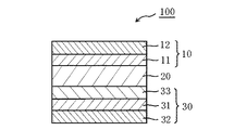
図1は、本発明の好ましい実施形態による液晶パネルの概略断面図である。図1の実施形態において、液晶パネル100は、視認側から第1の偏光板10、VAモードの液晶セル20、第2の偏光板30をこの順に備える。第1の偏光板10は、第1の偏光子11と、該第1の偏光子11の一方の面に配置された保護層12を含む。該第1の偏光板10は、任意の接着層(図示せず)を介して、第1の偏光子11と液晶セル20とが対向するよう配置され得る。第2の偏光板30は、第2の偏光子31と、該第2の偏光子31の一方の面に配置された保護層32と、該第2の偏光子31の他方の面に配置された位相差層33とを含む。該第2の偏光板30は、任意の接着層(図示せず)を介して、該位相差層33と液晶セル20とが対向するよう配置され得る。好ましくは、第1の偏光板10に含まれる第1の偏光子11の吸収軸と第2の偏光板30に含まれる第2の偏光子31の吸収軸とが実質的に直交するように配置され得る。
<A. Overview of LCD panel>
FIG. 1 is a schematic cross-sectional view of a liquid crystal panel according to a preferred embodiment of the present invention. In the embodiment of FIG. 1, the
本発明の液晶パネル100において、第1の偏光子11および第2の偏光子31は、それぞれRpvaの値が0.030≦Rpva≦0.040の関係を満たす。第1の偏光子11および第2の偏光子31が上記の関係を満たすことにより、正面方向におけるコントラストを向上させることができる。
In the
上記位相差層33は、目的、パネルの構成等に応じて、その遅相軸が第2の偏光子31の吸収軸に対して任意の適切な角度を規定するように配置される。例えば、位相差層33の遅相軸と第2の偏光子31の吸収軸とが実質的に直交するように配置され得る。
The
<B.液晶セル>
本発明に用いられる液晶セルとしては、任意の適切なものが採用され得る。上記液晶セルは、好ましくは、一対の基板と、該一対の基板に挟持された表示媒体としての液晶層を有する。一方の基板(アクティブマトリクス基板)には、液晶の電気光学特性を制御するスイッチング素子(代表的には、TFT)と、このスイッチング素子にゲート信号を与える走査線およびソース信号を与える信号線とが設けられる。他方の基板(カラーフィルター基板)には、カラーフィルターが設けられる。
<B. Liquid crystal cell>
Any appropriate liquid crystal cell may be employed as the liquid crystal cell used in the present invention. The liquid crystal cell preferably includes a pair of substrates and a liquid crystal layer as a display medium sandwiched between the pair of substrates. One substrate (active matrix substrate) includes a switching element (typically a TFT) for controlling the electro-optical characteristics of the liquid crystal, a scanning line for supplying a gate signal to the switching element, and a signal line for supplying a source signal. Provided. The other substrate (color filter substrate) is provided with a color filter.
上記カラーフィルターは、上記アクティブマトリクス基板に設けてもよい。あるいは、フィールドシーケンシャル方式のように液晶表示装置の照明手段にRGB3色光源(さらに、多色の光源を含んでいてもよい)が用いられる場合は、上記カラーフィルターは省略され得る。2つの基板の間隔(セルギャップ)は、スペーサーによって制御される。各基板の液晶層を接する側には、例えば、ポリイミドからなる配向膜が設けられる。あるいは、例えば、パターニングされた透明電極によって形成されるフリンジ電界を利用して、液晶分子の初期配向が制御される場合には、上記配向膜は省略され得る。 The color filter may be provided on the active matrix substrate. Alternatively, when an RGB three-color light source (which may further include a multicolor light source) is used as the illumination means of the liquid crystal display device as in the field sequential method, the color filter can be omitted. The distance (cell gap) between the two substrates is controlled by a spacer. For example, an alignment film made of polyimide is provided on the side of each substrate in contact with the liquid crystal layer. Alternatively, for example, when the initial alignment of liquid crystal molecules is controlled using a fringe electric field formed by a patterned transparent electrode, the alignment film can be omitted.
上記液晶セルは、好ましくは、ホメオトロピック配列に配向させた液晶分子を含む。本明細書において、「ホメオトロピック配列」とは、液晶分子の配向ベクトルが、配向処理された基板と液晶分子の相互作用の結果、基板平面に対し、垂直(法線方向に)に配向した状態のものをいう。なお、上記ホメオトロピック配列は、液晶分子の配向ベクトルが、基板法線方向に対し、わずかに傾いている場合、すなわち液晶分子がプレチルトを有する場合も包含される。液晶分子がプレチルトを有する場合は、そのプレチルト角(基板法線からの角度)は、好ましくは5°以下であり、より好ましくは3°以下である。プレチルト角を上記範囲とすることによって、コントラスト比の高い液晶表示装置が得られ得る。 The liquid crystal cell preferably includes liquid crystal molecules aligned in a homeotropic alignment. In this specification, “homeotropic alignment” means a state in which the alignment vector of liquid crystal molecules is aligned perpendicularly (in the normal direction) to the substrate plane as a result of the interaction between the alignment-treated substrate and the liquid crystal molecules. Means things. The homeotropic alignment includes a case where the alignment vector of the liquid crystal molecules is slightly inclined with respect to the normal direction of the substrate, that is, the case where the liquid crystal molecules have a pretilt. When the liquid crystal molecules have a pretilt, the pretilt angle (angle from the substrate normal) is preferably 5 ° or less, more preferably 3 ° or less. By setting the pretilt angle in the above range, a liquid crystal display device with a high contrast ratio can be obtained.
上記液晶分子は、目的に応じて、任意の適切なものが採用され得る。好ましくは、上記液晶分子は、誘電率異方性が負のネマチック液晶である。誘電率異方性が負のネマチック液晶は、例えば、共立出版(株)版「カラー液晶ディスプレイ」p.196 図6.2.10に記載の物が挙げられる。上記ネマチック液晶の23℃における波長589nmの光で測定した複屈折率は、好ましくは0.05〜0.15である。なお、上記複屈折率は、液晶分子を一様に均一に配向させ、異常光屈折率(ne)と常光屈折率(no)を測定し、その差(ne−no)から求めることができる。 Any appropriate liquid crystal molecules can be adopted depending on the purpose. Preferably, the liquid crystal molecule is a nematic liquid crystal having a negative dielectric anisotropy. A nematic liquid crystal having a negative dielectric anisotropy is described in, for example, “Color Liquid Crystal Display” p. 196 The thing of FIG. 6.2.10 is mentioned. The birefringence of the nematic liquid crystal measured with light having a wavelength of 589 nm at 23 ° C. is preferably 0.05 to 0.15. The birefringence can be obtained from the difference (ne-no) by aligning liquid crystal molecules uniformly and uniformly, measuring the extraordinary refractive index (ne) and the ordinary refractive index (no).
上記液晶セルの駆動モードは、バーティカル・アライメント(VA)モードである。該VAモードの液晶セルは、電圧制御複屈折効果を利用し、電界が存在しない状態で、ホメオトロピック配列に配向させた液晶分子を、基板に対して法線方向の電界で応答させる。具体的には、例えば、特開昭62−210423号公報や、特開平4−153621号公報に記載されているように、ノーマリブラック方式の場合、電界が存在しない状態では、液晶分子が基板に対して法線方向に配向しているために、上下の偏光板を直交配置させると、黒表示が得られる。一方、電界が存在する状態では、液晶分子が偏光板の吸収軸に対して、45°方位に倒れるように動作することによって、透過率が大きくなり、白表示が得られる。 The driving mode of the liquid crystal cell is a vertical alignment (VA) mode. The VA mode liquid crystal cell utilizes a voltage-controlled birefringence effect, and makes liquid crystal molecules aligned in a homeotropic alignment respond to the substrate with an electric field in a normal direction in the absence of an electric field. Specifically, as described in, for example, Japanese Patent Application Laid-Open No. 62-210423 and Japanese Patent Application Laid-Open No. 4-153621, in the case of a normally black method, liquid crystal molecules are formed on a substrate in the absence of an electric field. Therefore, when the upper and lower polarizing plates are arranged orthogonally, a black display can be obtained. On the other hand, in the presence of an electric field, the liquid crystal molecules operate so as to tilt in a 45 ° azimuth direction with respect to the absorption axis of the polarizing plate, whereby the transmittance increases and white display is obtained.
上記VAモードの液晶セルは、例えば、特開平11−258605号公報に記載されているように、電極にスリットを形成したものや、表面に突起を形成した基材を用いることによって、マルチドメイン化したものであってもよい。このような液晶セルは、例えば、シャープ(株)製 ASV(Advanced Super View)モード、同社製 CPA(Continuous Pinwheel Alignment)モード、富士通(株)製 MVA(Multi−domain Vertical Alignment)モード、三星電子(株)製 PVA(Patterned Vertical Alignment)モード、同社製 EVA(Enhanced Vertical Alignment)モード、三洋電機(株)製 SURVIVAL(Super Ranged Viewing by Vertical Alignment)モード等が挙げられる。 The VA mode liquid crystal cell can be multi-domained by using a substrate having slits formed on electrodes or a substrate having projections formed on the surface as described in JP-A-11-258605, for example. It may be what you did. Such a liquid crystal cell is, for example, an ASV (Advanced Super View) mode manufactured by Sharp Corporation, a CPA (Continuous Pinwheel Alignment) mode manufactured by the same company, an MVA (Multi-domain Vertical Alignment mode) manufactured by Fujitsu Limited, or the like. PVA (Patterned Vertical Alignment) mode manufactured by Co., Ltd., EVA (Enhanced Vertical Alignment) mode manufactured by the same company, SURVIVAL (Super Ranged Viewing by Vertical Alignment) mode manufactured by Sanyo Electric Co., Ltd., etc.
上記液晶セルは、市販の液晶表示装置に搭載されているものをそのまま用いてもよい。VAモードの液晶セルを含む、市販の液晶表示装置としては、例えば、シャープ(株)製 液晶テレビ 商品名「AQUOSシリーズ」、ソニー社製 液晶テレビ 商品名「BRAVIAシリーズ」、SUMSUNG社製 32V型ワイド液晶テレビ 商品名「LN32R51B」、(株)ナナオ製 液晶テレビ 商品名「FORIS SC26XD1」、AU Optronics社製 液晶テレビ 商品名「T460HW01」等が挙げられる。 As the liquid crystal cell, the one mounted on a commercially available liquid crystal display device may be used as it is. Commercially available liquid crystal display devices including VA mode liquid crystal cells include, for example, Sharp Corporation liquid crystal television product name “AQUIS series”, Sony liquid crystal television product name “BRAVIA series”, and SUMSUNG 32V type wide display. Liquid crystal television product name “LN32R51B”, Nanao Co., Ltd. liquid crystal television product name “FORIS SC26XD1”, AU Optronics liquid crystal television product name “T460HW01”, and the like.
<C.偏光板>
本発明に用いられる第1の偏光板10は、第1の偏光子11および保護層12を含む。本発明に用いられる第2の偏光板30は、第2の偏光子31、保護層32および位相差層33を含む。
<C. Polarizing plate>
The first
本発明に用いられる第1の偏光板および第2の偏光板の透過率は、好ましくは38.3%〜44.3%であり、さらに好ましくは39.2%〜44.2%であり、特に好ましくは41.1%〜44.2%であり、最も好ましくは41.7%〜44.2%である。透過率がこのような範囲であれば、正面方向のコントラスト比が高い液晶表示装置を得ることができる。なお、透過率は、平行透過率T0と直交透過率T90の平均として求められる。ここで、平行透過率T0は、同じ偏光子2枚を互いの吸収軸が平行となるように重ね合わせた平行型積層偏光子の透過率の値であり、直交透過率T90は、同じ偏光子2枚を互いの吸収軸が直交するように重ね合わせた直交型積層偏光子の透過率の値である。さらに、これらの透過率は、JlS Z 8701−1982の2度視野(C光源)により、視感度補正を行ったY値である。透過率は、例えば、分光光度計V7100を用いて測定することができる。 The transmittance of the first polarizing plate and the second polarizing plate used in the present invention is preferably 38.3% to 44.3%, more preferably 39.2% to 44.2%, It is particularly preferably 41.1% to 44.2%, and most preferably 41.7% to 44.2%. When the transmittance is in such a range, a liquid crystal display device having a high contrast ratio in the front direction can be obtained. The transmittance is obtained as an average of the parallel transmittance T 0 and the orthogonal transmittance T 90 . Here, the parallel transmittance T 0 is a transmittance value of a parallel laminated polarizer obtained by superimposing two identical polarizers so that their absorption axes are parallel to each other, and the orthogonal transmittance T 90 is the same. This is a transmittance value of an orthogonal laminated polarizer obtained by superposing two polarizers so that their absorption axes are orthogonal to each other. Further, these transmittances are Y values obtained by correcting the visibility with the 2-degree field of view (C light source) of JlS Z 8701-1982. The transmittance can be measured using, for example, a spectrophotometer V7100.
本発明に用いられる第1の偏光板および第2の偏光板の偏光度は、好ましくは99%以上であり、さらに好ましくは99.5%以上であり、特に好ましくは99.7%以上であり、最も好ましくは99.8%以上である。偏光度がこのような範囲であれば、正面方向のコントラスト比が高い液晶表示装置を得ることができる。 The degree of polarization of the first polarizing plate and the second polarizing plate used in the present invention is preferably 99% or more, more preferably 99.5% or more, and particularly preferably 99.7% or more. Most preferably, it is 99.8% or more. When the degree of polarization is in such a range, a liquid crystal display device having a high contrast ratio in the front direction can be obtained.
上記偏光度の具体的な測定方法としては、上記偏光板の平行透過率(T0)および直交透過率(T90)を測定し、式:偏光度(%)={(T0−T90)/(T0+T90)}1/2×100より求めることができる。平行透過率T0および直交透過率T90については、上記透過率の場合と同様である。上記偏光度は、分光光度計V7100を用いて測定することができる。 As a specific method for measuring the degree of polarization, the parallel transmittance (T 0 ) and orthogonal transmittance (T 90 ) of the polarizing plate are measured, and the formula: degree of polarization (%) = {(T 0 -T 90 ) / (T 0 + T 90 )} 1/2 × 100. The parallel transmittance T 0 and the orthogonal transmittance T 90 are the same as in the case of the above transmittance. The degree of polarization can be measured using a spectrophotometer V7100.
<C−1.偏光子>
本発明に用いられる第1の偏光子および第2の偏光子は、それぞれ0.030≦Rpva≦0.040を満足する。ここで、Rpvaは、波長1000nmにおいて、偏光子の面内で屈折率が最大になる方向の屈折率をnx、当該屈折率が最大になる方向に直交する方向の屈折率をnyとしたとき、Rpva=nx−nyで表される。第1の偏光子と第2の偏光子はRpvaが上記の範囲内であればよく、同一の偏光子であっても、異なる偏光子であってもよい。Rpvaは、好ましくは0.030≦Rpva≦0.039であり、さらに好ましくは0.030≦Rpva≦0.035である。これらの特性を満足することにより、本発明に用いられる偏光子は、加湿環境下において優れた寸法安定性および光学的耐久性を有し得る。その結果、本発明に用いられる偏光子は、偏光子の片側のみに保護層を設けた偏光板に用いられる場合でも、寸法変化および光学特性の劣化が起こりにくく、実用上許容可能な寸法安定性および光学的耐久性を実現することができる。したがって、本発明に用いられる液晶パネルは、生産性を低下させることなく薄型化が可能であり、かつ、正面方向のコントラストが向上した液晶表示装置を提供することができる。
<C-1. Polarizer>
Each of the first polarizer and the second polarizer used in the present invention satisfies 0.030 ≦ R pva ≦ 0.040. Here, R pva is, when the wavelength is 1000 nm, the refractive index in the direction in which the refractive index is maximum in the plane of the polarizer is nx, and the refractive index in the direction orthogonal to the direction in which the refractive index is maximum is ny. , R pva = nx−ny. The first polarizer and the second polarizer may have R pva in the above range, and may be the same polarizer or different polarizers. R pva is preferably 0.030 ≦ R pva ≦ 0.039, more preferably 0.030 ≦ R pva ≦ 0.035. By satisfying these characteristics, the polarizer used in the present invention can have excellent dimensional stability and optical durability in a humidified environment. As a result, even when the polarizer used in the present invention is used in a polarizing plate provided with a protective layer only on one side of the polarizer, dimensional change and optical property deterioration are unlikely to occur, and practically acceptable dimensional stability. And optical durability can be realized. Therefore, the liquid crystal panel used in the present invention can be thinned without reducing productivity, and can provide a liquid crystal display device with improved front contrast.
本発明に用いられる偏光子は、好ましくはヨウ素または二色性染料等の二色性物質を含有するポリビニルアルコール(PVA)系樹脂を主成分とする。 The polarizer used in the present invention is preferably composed mainly of a polyvinyl alcohol (PVA) resin containing a dichroic substance such as iodine or a dichroic dye.
本発明に用いられる偏光子のヨウ素含有量は、好ましくは1.8重量%〜5.0重量%であり、さらに好ましくは2.0重量%〜4.0重量%である。ヨウ素含有量を上記の範囲とすることによって、好ましい範囲の透過率の偏光板が得られ、正面方向のコントラスト比が高い液晶表示装置を得ることができる。 The iodine content of the polarizer used in the present invention is preferably 1.8% by weight to 5.0% by weight, and more preferably 2.0% by weight to 4.0% by weight. By setting the iodine content in the above range, a polarizing plate having a transmittance in a preferable range can be obtained, and a liquid crystal display device having a high contrast ratio in the front direction can be obtained.
本発明に用いられる偏光子のホウ酸含有量は、ホウ素換算で、好ましくは0.5重量%〜3.0重量%であり、さらに好ましくは1.0重量%〜2.8重量%であり、特に好ましくは1.5重量%〜2.6重量%である。上記のように、本発明によれば、ホウ酸量を増量することなく、加湿環境下において優れた寸法安定性および光学的耐久性を有する偏光子を得ることができる。 The boric acid content of the polarizer used in the present invention is preferably 0.5% to 3.0% by weight, more preferably 1.0% to 2.8% by weight, in terms of boron. Particularly preferably, it is 1.5% by weight to 2.6% by weight. As described above, according to the present invention, a polarizer having excellent dimensional stability and optical durability in a humidified environment can be obtained without increasing the amount of boric acid.
本発明に用いられる偏光子は、好ましくは、カリウムをさらに含有し得る。上記カリウム含有量は、好ましくは0.2重量%〜1.0重量%であり、さらに好ましくは0.3重量%〜0.9重量%であり、特に好ましくは0.4重量%〜0.8重量%である。カリウム含有量を上記範囲とすることによって、好ましい範囲の透過率を有し、かつ、偏光度が高い偏光板を得ることができる。 The polarizer used in the present invention may preferably further contain potassium. The potassium content is preferably 0.2% by weight to 1.0% by weight, more preferably 0.3% by weight to 0.9% by weight, and particularly preferably 0.4% by weight to 0.00%. 8% by weight. By making potassium content into the said range, the polarizing plate which has the transmittance | permeability of a preferable range and has high polarization degree can be obtained.
上記PVA系樹脂は、ビニルエステル系モノマーを重合して得られるビニルエステル系重合体をケン化することによって得ることができる。上記PVA系樹脂のケン化度は、好ましくは95.0モル%〜99.9モル%である。上記ケン化度は、JIS K 6726−1994に準じて求めることができる。ケン化度が上記の範囲であるPVA系樹脂を用いることによって、耐久性に優れた偏光子が得られ得る。 The PVA resin can be obtained by saponifying a vinyl ester polymer obtained by polymerizing a vinyl ester monomer. The saponification degree of the PVA resin is preferably 95.0 mol% to 99.9 mol%. The saponification degree can be determined according to JIS K 6726-1994. By using a PVA resin having a saponification degree in the above range, a polarizer having excellent durability can be obtained.
上記PVA系樹脂の平均重合度は、目的に応じて適切な値が選択され得る。上記平均重合度は、好ましくは1200〜3600である。なお、平均重合度は、JIS K 6726−1994に準じて求めることができる。 As the average degree of polymerization of the PVA-based resin, an appropriate value can be selected according to the purpose. The average degree of polymerization is preferably 1200 to 3600. The average degree of polymerization can be determined according to JIS K 6726-1994.
本発明に用いられる偏光子の厚みは特に制限されず、目的に応じて適切な厚みが採用され得る。当該厚みは、代表的には、1μm〜80μm程度である。 The thickness of the polarizer used in the present invention is not particularly limited, and an appropriate thickness can be adopted depending on the purpose. The thickness is typically about 1 μm to 80 μm.
<C−2.保護層>
上記保護層12および32としては、偏光板の保護層として使用できる任意の適切なフィルムで形成される。当該フィルムの主成分となる材料の具体例としては、トリアセチルセルロース(TAC)等のセルロース系樹脂や、ポリエステル系、ポリビニルアルコール系、ポリカーボネート系、ポリアミド系、ポリイミド系、ポリエーテルスルホン系、ポリスルホン系、ポリスチレン系、ポリノルボルネン系、ポリオレフィン系、(メタ)アクリル系、アセテート系等の透明樹脂等が挙げられる。好ましくは、上記保護層12および32は、セルロースアセテート系フィルムを含む。また、(メタ)アクリル系、ウレタン系、(メタ)アクリルウレタン系、エポキシ系、シリコーン系等の熱硬化型樹脂または紫外線硬化型樹脂等も挙げられる。この他にも、例えば、シロキサン系ポリマー等のガラス質系ポリマーも挙げられる。また、特開2001−343529号公報(WO01/37007)に記載のポリマーフィルムも使用できる。このフィルムの材料としては、例えば、側鎖に置換または非置換のイミド基を有する熱可塑性樹脂と、側鎖に置換または非置換のフェニル基ならびにニトリル基を有する熱可塑性樹脂を含有する樹脂組成物が使用でき、例えば、イソブテンとN−メチルマレイミドからなる交互共重合体と、アクリロニトリル・スチレン共重合体とを有する樹脂組成物が挙げられる。当該ポリマーフィルムは、例えば、上記樹脂組成物の押出成形物であり得る。
<C-2. Protective layer>
The protective layers 12 and 32 are formed of any appropriate film that can be used as a protective layer for a polarizing plate. Specific examples of the material as the main component of the film include cellulose resins such as triacetyl cellulose (TAC), polyester-based, polyvinyl alcohol-based, polycarbonate-based, polyamide-based, polyimide-based, polyethersulfone-based, and polysulfone-based materials. And transparent resins such as polystyrene, polynorbornene, polyolefin, (meth) acryl, and acetate. Preferably, the
上記保護層は、保護層の偏光子の透過軸に対して平行な方向の線膨張係数αが該偏光子の透過軸方向の線膨張係数よりも小さいことが好ましい。このような保護層を用いることにより、クラック耐久性が向上し得る。1つの実施形態においては、保護層の線膨張係数αは、4.5×10⁻⁵/℃以下であることが好ましく、−5.0×10−5/℃〜4.5×10−5/℃であることがより好ましく、−4.5×10−5/℃〜4.0×10−5/℃であることがさらに好ましい。 The protective layer preferably has a linear expansion coefficient α in a direction parallel to the transmission axis of the polarizer of the protective layer smaller than the linear expansion coefficient in the transmission axis direction of the polarizer. By using such a protective layer, the crack durability can be improved. In one embodiment, the linear expansion coefficient α of the protective layer is preferably 4.5 × 10 −5 / ° C. or less, and is −5.0 × 10 −5 / ° C. to 4.5 × 10 −5. more preferably from / ° C., more preferably from -4.5 × 10 -5 /℃~4.0×10 -5 / ℃ .
上記保護層は、TD方向の線膨張係数およびMD方向の線膨張係数のうち、少なくとも一方の線膨張係数が偏光子の透過軸方向の線膨張係数よりも小さければよく、偏光板の保護層として使用できる任意の適切なフィルムで形成される。このようなフィルムを、偏光子の透過軸に対して平行な方向の線膨張係数が偏光子の透過軸方向の線膨張係数よりも小さくなるよう配置すればよい。当該フィルムの主成分となる材料の具体例は、上記の通りである。好ましくは、上記フィルムは、セルロース系樹脂、ポリエステル系樹脂またはポリイミド系樹脂を主成分とするフィルムであり、より好ましくはトリアセチルセルロース樹脂、ポリエチレンテレフタレート樹脂、ポリエチレンナフタレート樹脂またはポリイミド樹脂を主成分とするフィルムである。好ましくは、上記保護層は、延伸フィルムである。 As the protective layer of the polarizing plate, it is sufficient that at least one of the linear expansion coefficient in the TD direction and the linear expansion coefficient in the MD direction is smaller than the linear expansion coefficient in the transmission axis direction of the polarizer. Formed with any suitable film that can be used. What is necessary is just to arrange | position such a film so that the linear expansion coefficient of the direction parallel to the transmission axis of a polarizer may become smaller than the linear expansion coefficient of the transmission axis direction of a polarizer. The specific example of the material used as the main component of the film is as described above. Preferably, the film is a film mainly composed of a cellulose resin, a polyester resin or a polyimide resin, more preferably a triacetyl cellulose resin, a polyethylene terephthalate resin, a polyethylene naphthalate resin or a polyimide resin as a main component. It is a film. Preferably, the protective layer is a stretched film.
また、上記保護層は、粒子を含む透明樹脂層であってもよい。該粒子を含む透明樹脂層は、透明バインダー樹脂および粒子を含む。該透明バインダー樹脂としては、任意の適切な樹脂を用いることができる。具体的には、上記の保護層として用いられるフィルムの主成分として例示した樹脂が用いられ得る。該粒子としては、任意の適切な粒子を用いることができ、無機粒子であってもよく、樹脂粒子であってもよい。該粒子の平均粒子径は、0.05μm〜2.0μmであることが好ましい。 The protective layer may be a transparent resin layer containing particles. The transparent resin layer containing the particles includes a transparent binder resin and particles. Any appropriate resin can be used as the transparent binder resin. Specifically, the resin exemplified as the main component of the film used as the protective layer may be used. Any appropriate particles can be used as the particles, and the particles may be inorganic particles or resin particles. The average particle diameter of the particles is preferably 0.05 μm to 2.0 μm.
上記保護層(外側保護層)12,32は、その表面に任意の適切な表面処理が施されてもよい。例えば、上記保護層として、表面処理が施された市販の高分子フィルムをそのまま用いることができる。あるいは、市販の高分子フィルムに任意の表面処理を施して用いることもできる。表面処理としては、防眩処理、拡散処理(アンチグレア処理)、反射防止処理(アンチリフレクション処理)、ハードコート処理、帯電防止処理等が挙げられる。視認側の保護層12は、好ましくは防眩処理が施されている。視認側に配置される保護層12に、防眩処理が施されていることにより、正面方向のコントラストをより向上させることができる。防眩処理方法としては任意の適切な方法を用いることができる。例えばエンボス加工、サンドブラスト加工やエッチング加工等の適宜な方式で表面に微細凹凸構造を付与することなどにより、表面反射光が拡散する適宜な方式で形成することができる。
The protective layers (outer protective layers) 12 and 32 may be subjected to any appropriate surface treatment on the surfaces thereof. For example, as the protective layer, a commercially available polymer film subjected to surface treatment can be used as it is. Alternatively, a commercially available polymer film can be used after any surface treatment. Examples of the surface treatment include an antiglare treatment, a diffusion treatment (antiglare treatment), an antireflection treatment (antireflection treatment), a hard coat treatment, and an antistatic treatment. The
<C−3.位相差層>
本発明に用いられる位相差層33は、第2の偏光子31の一方の面に配置される。該位相差層33は、好ましくは屈折率楕円体がnx>ny>nzの関係を示し、かつ、位相差層33の厚み方向の位相差Rth[590]が150nm〜400nmである。上記の位相差フィルムを用いることにより、位相差層を1層配置するだけで、液晶セルを光学的に補償することができ、薄型で低コストの液晶パネルが得られるという利点がある。
<C-3. Retardation layer>
The
上記位相差層のRe[590]は好ましくは10nm以上であり、より好ましくは20nm〜80nmであり、さらに好ましくは30nm〜70nmであり、特に好ましくは40nm〜70nmである。Re[590]を上記範囲とすることによって、正面方向のコントラスト比の高い、優れた表示特性を示す液晶表示装置を得ることができる。 Re [590] of the retardation layer is preferably 10 nm or more, more preferably 20 nm to 80 nm, still more preferably 30 nm to 70 nm, and particularly preferably 40 nm to 70 nm. By setting Re [590] in the above range, a liquid crystal display device having a high contrast ratio in the front direction and excellent display characteristics can be obtained.
上記位相差層の厚み方向の位相差Rth[590]は、好ましくは150nm〜400nmであり、さらに好ましくは180nm〜300nmであり、より好ましくは200nm〜300nmである。Rth[590]を上記範囲とすることによって、正面方向のコントラスト比の高い、優れた表示特性を示す液晶表示装置を得ることができる。 The retardation Rth [590] in the thickness direction of the retardation layer is preferably 150 nm to 400 nm, more preferably 180 nm to 300 nm, and more preferably 200 nm to 300 nm. By setting Rth [590] in the above range, a liquid crystal display device having a high contrast ratio in the front direction and excellent display characteristics can be obtained.
上記位相差層の屈折率楕円体がnx>ny>nzの関係を示す場合、Rth[590]はRe[590]よりも大きい。すなわち、上記位相差層のNz係数は1より大きい。上記Nz係数は、好ましくは1.1を超え8以下であり、さらに好ましくは2〜7であり、特に好ましくは2〜6である。Nz係数を上記範囲とすることによって、正面方向のコントラスト比の高い、優れた表示特性を示す液晶表示装置を得ることができる。 When the refractive index ellipsoid of the retardation layer shows a relationship of nx> ny> nz, Rth [590] is larger than Re [590]. That is, the Nz coefficient of the retardation layer is greater than 1. The Nz coefficient is preferably more than 1.1 and 8 or less, more preferably 2 to 7, and particularly preferably 2 to 6. By setting the Nz coefficient in the above range, a liquid crystal display device having a high contrast ratio in the front direction and excellent display characteristics can be obtained.
上記位相差層の厚みは、好ましくは0.5μm〜200μmである。 The thickness of the retardation layer is preferably 0.5 μm to 200 μm.
上記位相差層を形成する材料としては、位相差層が上記の特性を有するものであれば、任意の適切な材料を用いることができる。上記位相差層は、好ましくはセルロース系樹脂またはノルボルネン系樹脂等のシクロオレフィン系樹脂を含む位相差フィルムである。 As a material for forming the retardation layer, any appropriate material can be used as long as the retardation layer has the above-described characteristics. The retardation layer is preferably a retardation film containing a cycloolefin resin such as a cellulose resin or a norbornene resin.
〔セルロース系樹脂〕
上記セルロース系樹脂は、任意の適切なものが採用され得る。上記セルロース系樹脂は、好ましくは、セルロースの水酸基の一部又は全部がアセチル基、プロピオニル基及び/又はブチル基で置換された、セルロース有機酸エステル又はセルロース混合有機酸エステルである。上記セルロース有機酸エステルとしては、例えば、セルロースアセテート、セルロースプロピオネート、セルロースブチレート等が挙げられる。上記セルロース混合有機酸エステルとしては、例えば、セルロースアセテートプロピオネート、セルロースアセテートブチレート等が挙げられる。上記セルロース系樹脂は、例えば、特開2001−188128号公報[0040]〜[0041]に記載の方法により得ることができる。
[Cellulosic resin]
Arbitrary appropriate things can be employ | adopted for the said cellulose resin. The cellulose resin is preferably a cellulose organic acid ester or a cellulose mixed organic acid ester in which some or all of the hydroxyl groups of cellulose are substituted with acetyl groups, propionyl groups, and / or butyl groups. Examples of the cellulose organic acid ester include cellulose acetate, cellulose propionate, and cellulose butyrate. Examples of the cellulose mixed organic acid ester include cellulose acetate propionate and cellulose acetate butyrate. The cellulose resin can be obtained by, for example, the method described in JP 2001-188128 A [0040] to [0041].
上記セルロースアセテートのアセチル置換度は、好ましくは2.0〜3.0であり、さらに好ましくは2.5〜3.0である。上記セルロースプロピオネートのプロピオニル置換度は、好ましくは2.0〜3.0であり、さらに好ましくは2.5〜3.0である。上記セルロース系樹脂が、セルロースの水酸基の一部がアセチル基で置換され一部がプロピオニル基で置換された混合有機酸エステルである場合、そのアセチル置換度とプロピオニル置換度の合計は、好ましくは2.0〜3.0であり、さらに好ましくは2.5〜3.0である。この場合、アセチル置換度は好ましくは0.1〜2.9であり、プロピオニル置換度は好ましくは0.1〜2.9である。 The acetyl substitution degree of the cellulose acetate is preferably 2.0 to 3.0, more preferably 2.5 to 3.0. The propionyl substitution degree of the cellulose propionate is preferably 2.0 to 3.0, more preferably 2.5 to 3.0. When the cellulose-based resin is a mixed organic acid ester in which a part of the hydroxyl groups of cellulose is substituted with an acetyl group and a part thereof is substituted with a propionyl group, the total of the degree of acetyl substitution and the degree of propionyl substitution is preferably 2 It is 0.0-3.0, More preferably, it is 2.5-3.0. In this case, the degree of acetyl substitution is preferably 0.1 to 2.9, and the degree of propionyl substitution is preferably 0.1 to 2.9.
本明細書において、アセチル置換度(又はプロピオニル置換度)とは、セルロース骨格における2、3、6位の炭素についた水酸基をアセチル基(又はプロピオニル基)で置換した数を示す。セルロース骨格における2、3、6位の炭素のどれかにアセチル基(又はプロピオニル基)が偏ってもよく、それぞれの炭素に平均的に存在してもよい。上記アセチル置換度は、ASTM−D817−91(セルロースアセテート等の試験法)によって求めることができる。また、上記プロピオニル置換度は、ASTM−D817−96(セルロースアセテート等の試験法)によって求めることができる。 In the present specification, the acetyl substitution degree (or propionyl substitution degree) indicates the number of hydroxyl groups attached to carbons at the 2, 3, 6 positions in the cellulose skeleton with acetyl groups (or propionyl groups). The acetyl group (or propionyl group) may be biased to any of the carbons at the 2, 3 and 6 positions of the cellulose skeleton, and may be present on average in each carbon. The said acetyl substitution degree can be calculated | required by ASTM-D817-91 (test methods, such as a cellulose acetate). Moreover, the said propionyl substitution degree can be calculated | required by ASTM-D817-96 (test methods, such as a cellulose acetate).
上記セルロース系樹脂の重量平均分子量(Mw)は、テトラヒドロフラン溶媒によるゲル・パーミエーション・クロマトグラフ法(ポリスチレン標準)で測定した値が、好ましくは20,000〜1,000,000である。上記セルロース系樹脂のガラス転移温度(Tg)は、好ましくは110℃〜185℃である。なお、ガラス転移温度(Tg)は、JIS K 7121に準じたDSC法により求めることができる。上記の樹脂であれば、優れた熱安定性を有し、機械的強度に優れたフィルムが得られ得る。 The weight average molecular weight (Mw) of the cellulose resin is preferably 20,000 to 1,000,000, as measured by gel permeation chromatography (polystyrene standard) using a tetrahydrofuran solvent. The glass transition temperature (Tg) of the cellulose resin is preferably 110 ° C to 185 ° C. The glass transition temperature (Tg) can be determined by a DSC method according to JIS K7121. If it is said resin, it has the outstanding thermal stability and the film excellent in mechanical strength can be obtained.
上記セルロース系樹脂を含有する位相差フィルムは、任意の適切な成形加工法によって得ることができる。好ましくは、上記セルロース系樹脂を含有する位相差フィルムは、ソルベントキャスティング法によって、シート状に成形されたフィルムを、横一軸延伸法、縦横同時二軸延伸法、又は縦横逐次二軸延伸法により、延伸して作製される。上記フィルムを延伸する温度(延伸温度)は、好ましくは120℃〜200℃である。また、上記フィルムを延伸する倍率(延伸倍率)は、好ましくは1を超え3倍以下である。 The retardation film containing the cellulose resin can be obtained by any appropriate forming method. Preferably, the retardation film containing the cellulose-based resin is a film formed into a sheet shape by a solvent casting method, a horizontal uniaxial stretching method, a vertical and horizontal simultaneous biaxial stretching method, or a vertical and horizontal sequential biaxial stretching method. Made by stretching. The temperature at which the film is stretched (stretching temperature) is preferably 120 ° C to 200 ° C. Moreover, the magnification (stretching ratio) for stretching the film is preferably more than 1 and not more than 3 times.
上記位相差フィルムは、市販のフィルムをそのまま用いることができる。あるいは、市販のフィルムに延伸処理及び/又は収縮処理などの2次的加工を施したものを用いることができる。市販のセルロース系樹脂を含有する高分子フィルムとしては、例えば、富士写真フィルム(株)製 フジタックシリーズ(商品名;ZRF80S,TD80UF,TDY−80UL)、コニカミノルタオプト(株)製 商品名「KC8UX2M」等が挙げられる。 As the retardation film, a commercially available film can be used as it is. Alternatively, a commercially available film subjected to secondary processing such as stretching and / or shrinking can be used. As a polymer film containing a commercially available cellulose resin, for example, Fuji Photo Film Co., Ltd. Fujitac series (trade name: ZRF80S, TD80UF, TDY-80UL), Konica Minolta Opto Co., Ltd. trade name “KC8UX2M” Or the like.
〔シクロオレフィン系樹脂〕
上記シクロオレフィン系樹脂としては、例えば、ノルボルネン系樹脂を好適に用いることができる。ノルボルネン系樹脂は、光弾性係数の絶対値(C[590])が小さいため、光学的なムラの小さい液晶表示装置を得ることができる。上記ノルボルネン系樹脂のC[590]は、好ましくは1×10⁻¹²〜20×10−12であり、さらに好ましくは1×10⁻¹²〜10×10−12である。本明細書において「ノルボルネン系樹脂」とは、出発原料(モノマー)の一部または全部に、ノルボルネン環を有するノルボルネン系モノマーを用いて得られる(共)重合体をいう。上記「(共)重合体」は、ホモポリマーまたは共重合体(コポリマー)を表す。
[Cycloolefin resin]
For example, a norbornene resin can be suitably used as the cycloolefin resin. Since the norbornene-based resin has a small absolute value (C [590]) of the photoelastic coefficient, a liquid crystal display device with small optical unevenness can be obtained. C [590] of the norbornene-based resin is preferably 1 × 10 −12 to 20 × 10 −12 , and more preferably 1 × 10 −12 to 10 × 10 −12 . In this specification, the “norbornene-based resin” refers to a (co) polymer obtained by using a norbornene-based monomer having a norbornene ring as a part or all of a starting material (monomer). The “(co) polymer” represents a homopolymer or a copolymer (copolymer).
上記ノルボルネン系樹脂は、出発原料としてノルボルネン環(ノルボルナン環に二重結合を有するもの)を有するノルボルネン系モノマーが用いられる。上記ノルボルネン系樹脂は、(共)重合体の状態では、構成単位にノルボルナン環を有していても、有していなくてもよい。(共)重合体の状態では、構成単位にノルボルナン環を有するノルボルネン系樹脂は、例えば、テトラシクロ[4.4.12,5.17,10.0]デカ−3−エン、8−メチルテトラシクロ[4.4.12,5.17,10.0]デカ−3−エン、8−メトキシカルボニルテトラシクロ[4.4.12,5.17,10.0]デカ−3−エン等が挙げられる。(共)重合体の状態で構成単位にノルボルナン環を有さないノルボルネン系樹脂は、例えば、開裂により5員環となるモノマーを用いて得られる(共)重合体である。上記開裂により5員環となるモノマーとしては、例えば、ノルボルネン、ジシクロペンタジエン、5−フェニルノルボルネン等やそれらの誘導体等が挙げられる。上記ノルボルネン系樹脂が共重合体である場合、その分子の配列状態は、特に制限はなく、ランダム共重合体であってもよいし、ブロック共重合体であってもよいし、グラフト共重合体であってもよい。 In the norbornene-based resin, a norbornene-based monomer having a norbornene ring (having a double bond in the norbornane ring) is used as a starting material. In the state of the (co) polymer, the norbornene-based resin may or may not have a norbornane ring in the structural unit. In the state of the (co) polymer, the norbornene-based resin having a norbornane ring as a structural unit is, for example, tetracyclo [4.4.1 2,5 . 1 7,10 . 0] Dec-3-ene, 8-methyltetracyclo [4.4.1 2,5 . 1 7,10 . 0] dec-3-ene, 8-methoxycarbonyltetracyclo [4.4.1 2,5 . 1 7,10 . 0] Dec-3-ene and the like. A norbornene-based resin having no norbornane ring as a structural unit in the (co) polymer state is, for example, a (co) polymer obtained using a monomer that becomes a 5-membered ring by cleavage. Examples of the monomer that becomes a 5-membered ring by cleavage include norbornene, dicyclopentadiene, 5-phenylnorbornene, and derivatives thereof. When the norbornene-based resin is a copolymer, the arrangement state of the molecules is not particularly limited, and may be a random copolymer, a block copolymer, or a graft copolymer. It may be.
上記ノルボルネン系樹脂としては、例えば、(A)ノルボルネン系モノマーの開環(共)重合体を水素添加した樹脂、(B)ノルボルネン系モノマーを付加(共)重合させた樹脂などが挙げられる。上記ノルボルネン系モノマーの開環共重合体は、1種以上のノルボルネン系モノマーと、α−オレフィン類、シクロアルケン類、および/または非共役ジエン類との開環共重合体を水素添加した樹脂を包含する。上記ノルボルネン系モノマーを付加共重合させた樹脂は、1種以上のノルボルネン系モノマーと、α−オレフィン類、シクロアルケン類および/または非共役ジエン類との付加型共重合させた樹脂を包含する。 Examples of the norbornene resin include (A) a resin obtained by hydrogenating a ring-opening (co) polymer of a norbornene monomer, and (B) a resin obtained by addition (co) polymerization of a norbornene monomer. The ring-opening copolymer of the norbornene-based monomer is a resin obtained by hydrogenating a ring-opening copolymer of one or more norbornene-based monomers and α-olefins, cycloalkenes, and / or non-conjugated dienes. Include. The resin obtained by addition copolymerization of the norbornene monomer includes a resin obtained by addition copolymerization of one or more norbornene monomers with α-olefins, cycloalkenes and / or non-conjugated dienes.
上記ノルボルネン系モノマーの開環(共)重合体を水素添加した樹脂は、ノルボルネン系モノマー等をメタセシス反応させて、開環(共)重合体を得、さらに、当該開環(共)重合体を水素添加して得ることができる。具体的には、例えば、特開平11−116780号公報の段落[0059]〜[0060]に記載の方法、特開2001−350017号公報の段落[0035]〜[0037]に記載の方法等が挙げられる。上記ノルボルネン系モノマーを付加(共)重合させた樹脂は、例えば、特開昭61−292601号公報の実施例1に記載の方法により得ることができる。 A resin obtained by hydrogenating the ring-opening (co) polymer of the norbornene monomer is subjected to a metathesis reaction of the norbornene monomer or the like to obtain a ring-opening (co) polymer. It can be obtained by hydrogenation. Specifically, for example, the method described in paragraphs [0059] to [0060] of JP-A-11-116780, the method described in paragraphs [0035] to [0037] of JP-A-2001-350017, and the like. Can be mentioned. The resin obtained by addition (co) polymerization of the norbornene monomer can be obtained, for example, by the method described in Example 1 of JP-A No. 61-292601.
上記ノルボルネン系樹脂の重量平均分子量(Mw)は、テトラヒドロフラン溶媒によるゲル・パーミエーション・クロマトグラフ法(ポリスチレン標準)で測定した値が、好ましくは、20,000〜500,000である。上記ノルボルネン系樹脂のガラス転移温度(Tg)は、好ましくは120℃〜170℃である。上記の樹脂であれば、優れた熱安定性を有し、延伸性に優れたフィルムが得られ得る。なお、ガラス転移温度(Tg)は、JIS K 7121に準じたDSC法により算出される値である。 The weight average molecular weight (Mw) of the norbornene resin is preferably 20,000 to 500,000 as measured by gel permeation chromatography (polystyrene standard) using a tetrahydrofuran solvent. The glass transition temperature (Tg) of the norbornene-based resin is preferably 120 ° C to 170 ° C. If it is said resin, it has the outstanding thermal stability and the film excellent in the drawability can be obtained. The glass transition temperature (Tg) is a value calculated by the DSC method according to JIS K7121.
上記ノルボルネン系樹脂を含む位相差フィルムは、任意の適切な成形加工法によって得ることができる。好ましくは、上記ノルボルネン系樹脂を含む位相差フィルムは、ソルベントキャスティング法または溶融押出法によって、シート状に成形された高分子フィルムを、横一軸延伸法、縦横同時二軸延伸法、または縦横逐次二軸延伸法により、延伸して作製される。上記高分子フィルムを延伸する温度(延伸温度)は、好ましくは120℃〜200℃である。また、上記高分子フィルムを延伸する倍率(延伸倍率)は、好ましくは1を超え3倍以下である。 The retardation film containing the norbornene resin can be obtained by any appropriate forming method. Preferably, the retardation film containing the norbornene-based resin is obtained by converting a polymer film formed into a sheet shape by a solvent casting method or a melt extrusion method into a transverse uniaxial stretching method, a longitudinal and transverse simultaneous biaxial stretching method, or a longitudinal and transverse sequential two-phase method. It is produced by stretching by an axial stretching method. The temperature at which the polymer film is stretched (stretching temperature) is preferably 120 ° C to 200 ° C. Moreover, the magnification (stretching ratio) for stretching the polymer film is preferably more than 1 and not more than 3 times.
上記位相差フィルムは、任意の適切な添加剤をさらに含有し得る。上記添加剤としては、例えば、可塑剤、熱安定剤、光安定剤、滑剤、抗酸化剤、紫外線吸収剤、難燃剤、着色剤、帯電防止剤、相溶化剤、架橋剤、及び増粘剤等が挙げられる。上記添加剤の含有量は、好ましくは、上記ノルボルネン系樹脂100重量部に対し、0を超え10重量部以下である。 The retardation film may further contain any appropriate additive. Examples of the additive include a plasticizer, a heat stabilizer, a light stabilizer, a lubricant, an antioxidant, an ultraviolet absorber, a flame retardant, a colorant, an antistatic agent, a compatibilizer, a crosslinking agent, and a thickener. Etc. The content of the additive is preferably more than 0 and 10 parts by weight or less with respect to 100 parts by weight of the norbornene resin.
第1の偏光板10における第1の偏光子11と保護層12、および、第2の偏光板30における第2の偏光子31と保護層32、第2の偏光子31と位相差層33とは、任意の適切な接着層を介して、積層させることができる。本明細書において、「接着層」とは、隣り合う光学部材の面と面とを接合し、実用上十分な接着力と接着時間で一体化させるものをいう。上記接着層を形成する材料としては、例えば、接着剤、粘着剤、アンカーコート剤が挙げられる。上記接着層は、被着体の表面にアンカーコート層が形成され、その上に接着剤層が形成されたような、多層構造であってもよい。また、肉眼的に認知できないような薄い層(ヘアーラインともいう)であってもよい。
The
上記接着層の厚みは、目的に応じて、任意の適切な値に設定され得る。上記接着層の厚みは、好ましくは0.01μm〜50μmである。接着層の厚みを上記の範囲とすることによって、接合される偏光子に浮きや剥がれが生じず、実用上十分な接着力と接着時間が得られ得る。 The thickness of the adhesive layer can be set to any appropriate value depending on the purpose. The thickness of the adhesive layer is preferably 0.01 μm to 50 μm. By setting the thickness of the adhesive layer in the above range, the polarizer to be joined does not float or peel off, and a practically sufficient adhesive force and adhesive time can be obtained.
上記接着層を形成する材料としては、被着体の種類や目的に応じて、任意の適切なものが選択され得る。上記偏光子が、ヨウ素を含有するポリビニルアルコール系樹脂を主成分とする場合、上記接着層を形成する材料としては、好ましくは、水溶性接着剤である。上記水溶性接着剤としては、好ましくは、ポリビニルアルコール系樹脂を主成分とする水溶性接着剤である。上記接着層は、市販の接着剤をそのまま用いることもできる。あるいは、市販の接着剤に溶剤や添加剤を混合して用いることもできる。市販のポリビニルアルコール系樹脂を主成分とする接着剤としては、例えば、日本合成化学工業(株)製 ゴーセノールシリーズ(商品名「NH−18S、GH−18S、T−300等」)、同社製 ゴーセファイマーシリーズ(商品名「Z−100、Z−200、Z−210等」)等が挙げられる。 Any appropriate material can be selected as the material for forming the adhesive layer depending on the type and purpose of the adherend. In the case where the polarizer contains a polyvinyl alcohol resin containing iodine as a main component, the material for forming the adhesive layer is preferably a water-soluble adhesive. The water-soluble adhesive is preferably a water-soluble adhesive mainly composed of a polyvinyl alcohol resin. A commercially available adhesive can be used as it is for the adhesive layer. Or a solvent and an additive can also be mixed and used for a commercially available adhesive agent. As an adhesive mainly composed of a commercially available polyvinyl alcohol resin, for example, GOHSENOL series (trade name “NH-18S, GH-18S, T-300, etc.”) manufactured by Nippon Synthetic Chemical Industry Co., Ltd., the company Manufactured by Gohse-Fimer series (trade names “Z-100, Z-200, Z-210, etc.”) and the like.
<D.接着層>
好ましい実施形態においては、上記偏光板(第1の偏光板および第2の偏光板)は、接着層を介して液晶パネルを構成する他の部材に貼着される。上記接着層を形成する材料としては、被着体の種類や用途に応じて、適切な接着剤および/またはアンカーコート剤が選択され得る。接着剤の具体例としては、形状による分類によれば、溶剤形接着剤、エマルジョン形接着剤、感圧性接着剤、再湿性接着剤、重縮合形接着剤、無溶剤形接着剤、フィルム状接着剤、ホットメルト形接着剤などが挙げられる。化学構造による分類によれば、合成樹脂接着剤、ゴム系接着剤、および天然物接着剤が挙げられる。なお、上記接着剤は、加圧接触で感知しうる接着力を常温で示す粘弾性物質(粘着剤ともいう)を包含する。
<D. Adhesive layer>
In preferable embodiment, the said polarizing plate (a 1st polarizing plate and a 2nd polarizing plate) is affixed on the other member which comprises a liquid crystal panel through an contact bonding layer. As the material for forming the adhesive layer, an appropriate adhesive and / or anchor coat agent can be selected according to the type and application of the adherend. Specific examples of adhesives include solvent-based adhesives, emulsion-type adhesives, pressure-sensitive adhesives, rehumidifying adhesives, polycondensation-type adhesives, solventless adhesives, and film-like adhesives according to the classification by shape. Agents, hot melt adhesives, and the like. According to the classification by chemical structure, synthetic resin adhesives, rubber adhesives, and natural product adhesives can be mentioned. The adhesive includes a viscoelastic substance (also referred to as an adhesive) that exhibits an adhesive force that can be sensed by pressure contact at room temperature.
好ましくは、上記接着層を形成する材料は、アクリル系重合体をベースポリマーとする感圧性接着剤(アクリル系粘着剤ともいう)である。透明性、接着性、耐候性、および耐熱性に優れるからである。上記アクリル系粘着剤層の厚みは、被着体の材質や用途に応じて、適宜、調整され得るが、通常、5μm〜50μmである。 Preferably, the material forming the adhesive layer is a pressure-sensitive adhesive (also referred to as an acrylic pressure-sensitive adhesive) having an acrylic polymer as a base polymer. It is because it is excellent in transparency, adhesiveness, weather resistance, and heat resistance. The thickness of the acrylic pressure-sensitive adhesive layer can be appropriately adjusted according to the material and application of the adherend, but is usually 5 μm to 50 μm.
<E.液晶パネルの製造方法>
本発明に用いられる液晶パネルは、例えば、液晶セルに上記の構成要素(第1および第2の偏光子、保護層、位相差層)を順次積層することにより作製され得る。また、例えば、第1の偏光子と保護層とが積層された第1の積層体(第1の偏光板)と、第2の偏光子と位相差層と保護層とが積層された第2の積層体(第2の偏光板)とを作製し、次いで、当該第1および第2の積層体を液晶セルに貼り合せることにより作製されてもよい。
<E. Manufacturing method of liquid crystal panel>
The liquid crystal panel used in the present invention can be produced, for example, by sequentially laminating the above constituent elements (first and second polarizers, protective layer, retardation layer) on a liquid crystal cell. For example, the 1st laminated body (1st polarizing plate) by which the 1st polarizer and the protective layer were laminated | stacked, and the 2nd by which the 2nd polarizer, phase difference layer, and the protective layer were laminated | stacked. The laminate (second polarizing plate) may be prepared, and then the first and second laminates may be bonded to a liquid crystal cell.
従来のPVA系樹脂を用いた偏光子は寸法安定性に劣るため、片側のみに保護層が設けられた偏光板では、偏光子の寸法変化が起こりやすく、例えば、偏光板にカールが生じる。そのため、液晶セル等の他の部材との積層が困難となり、生産性に劣る。しかしながら、本発明に用いられる液晶パネルに用いられる第1の偏光子および第2の偏光子は、特に加湿環境下での寸法安定性に優れるため、上記第1の偏光板および第2の偏光板のように、保護層が片側にしか積層されていない形態であっても、偏光子の寸法変化に由来するカールの発生を抑制することができる。これにより、従来は困難であった片側にのみ保護層を有する偏光板を、連続的に積層することが可能となり、生産性が向上する。また、液晶パネルに含まれる保護層の枚数を減らすことにより、保護層が有する光学特性に起因する表示特性への影響を抑えることができ、かつ、液晶表示装置の薄型化に寄与し得る。 A polarizer using a conventional PVA-based resin is inferior in dimensional stability. Therefore, in a polarizing plate in which a protective layer is provided only on one side, the dimensional change of the polarizer is likely to occur. For example, curling occurs in the polarizing plate. Therefore, lamination with other members such as a liquid crystal cell becomes difficult, resulting in poor productivity. However, since the first polarizer and the second polarizer used in the liquid crystal panel used in the present invention are excellent in dimensional stability particularly in a humidified environment, the first polarizing plate and the second polarizing plate. As described above, even when the protective layer is laminated only on one side, the occurrence of curling due to the dimensional change of the polarizer can be suppressed. Thereby, it becomes possible to laminate | stack the polarizing plate which has a protective layer only on the one side which was difficult conventionally, and productivity improves. Further, by reducing the number of protective layers included in the liquid crystal panel, the influence on the display characteristics due to the optical characteristics of the protective layers can be suppressed, and the liquid crystal display device can be reduced in thickness.
上記の液晶パネルの各構成要素の積層方法としては、任意の適切な方法を採用し得る。代表的には、任意の適切な接着層(図示せず)を介して積層される。接着層を形成する材料としては上記D項に記載の材料を用いることができる。 Any appropriate method can be adopted as a method of laminating each component of the liquid crystal panel. Typically, it is laminated via any suitable adhesive layer (not shown). As a material for forming the adhesive layer, the materials described in the above section D can be used.
<F.液晶表示装置>
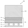
本発明の液晶表示装置は、上記液晶パネルを含む。図2は、本発明の好ましい実施形態による液晶表示装置の概略断面図である。なお、見やすくするために、図2の各構成部材の縦、横および厚みの比率は、実際とは異なっていることに留意されたい。この液晶表示装置200は、液晶パネル100と、液晶パネル100の一方の側に配置されたバックライトユニット80とを備える。なお、図示例では、バックライトユニットとして、直下方式が採用された場合を示しているが、これは例えば、サイドライト方式のものであってもよい。
<F. Liquid crystal display>
The liquid crystal display device of the present invention includes the liquid crystal panel. FIG. 2 is a schematic cross-sectional view of a liquid crystal display device according to a preferred embodiment of the present invention. It should be noted that the ratios of the vertical, horizontal, and thickness of each component shown in FIG. The liquid
直下方式が採用される場合、上記バックライトユニット80は、好ましくは、光源81と、反射フィルム82と、拡散板83と、プリズムシート84と、輝度向上フィルム85とを備える。サイドライト方式が採用される場合、好ましくは、バックライトユニットは、上記の構成に加え、さらに導光板と、ライトリフレクターとを備える。なお、図2に例示した光学部材は、本発明の効果が奏する限りにおいて、液晶表示装置の照明方式や液晶セルの駆動モードなど、用途に応じてその一部が省略され得るか、または、他の光学部材に代替され得る。
When the direct type is adopted, the
上記液晶表示装置は、液晶パネルの背面から光を照射して画面を見る、透過型であっても良いし、液晶パネルの視認側から光を照射して画面を見る、反射型であっても良い。あるいは、上記液晶表示装置は、透過型と反射型の両方の性質を併せ持つ、半透過型であっても良い。 The liquid crystal display device may be a transmissive type that irradiates light from the back side of the liquid crystal panel to view the screen, or a reflective type that irradiates light from the viewing side of the liquid crystal panel to view the screen. good. Alternatively, the liquid crystal display device may be a transflective type having both transmissive and reflective properties.
本発明の液晶表示装置は、任意の適切な用途に使用される。その用途は、例えば、パソコンモニター,ノートパソコン,コピー機などのOA機器、携帯電話,時計,デジタルカメラ,携帯情報端末(PDA),携帯ゲーム機などの携帯機器、ビデオカメラ,テレビ,電子レンジなどの家庭用電気機器、バックモニター,カーナビゲーションシステム用モニター,カーオーディオなどの車載用機器、商業店舗用インフォメーション用モニターなどの展示機器、監視用モニターなどの警備機器、介護用モニター,医療用モニターなどの介護・医療機器等である。 The liquid crystal display device of the present invention is used for any appropriate application. Applications include, for example, OA equipment such as personal computer monitors, notebook computers, and copiers, mobile phones, watches, digital cameras, personal digital assistants (PDAs), portable devices such as portable game machines, video cameras, televisions, microwave ovens, etc. Home appliances, back monitors, car navigation system monitors, car audio and other in-vehicle equipment, exhibition equipment such as commercial store information monitors, security equipment such as surveillance monitors, nursing care monitors, medical monitors, etc. Nursing care / medical equipment.
以下、実施例によって本発明を具体的に説明するが、本発明はこれら実施例によって限定されるものではない。なお、実施例で用いた各分析方法は、以下の通りである。
(1)Rpva
実施例および比較例で用いた偏光子について、王子計測社製の近赤外位相差測定装置KOBRA−31X100/IR(波長1000nm、23℃)を用いて測定した。
(2)パネルコントラスト
各実施例または比較例で得られた液晶パネルを、第1の偏光板が視認側に、第2の偏光板がバックライト側になるよう、液晶テレビ(シャープ(株)製の「LC−32DE5」)のバックライトユニットに組み込み、液晶表示装置を作製した。得られた液晶表示装置について、トプコン製のSR−UL1Rにてコントラストを算出した。
EXAMPLES Hereinafter, although an Example demonstrates this invention concretely, this invention is not limited by these Examples. In addition, each analysis method used in the Example is as follows.
(1) R pva
About the polarizer used by the Example and the comparative example, it measured using the near infrared phase difference measuring apparatus KOBRA-31X100 / IR (wavelength 1000nm, 23 degreeC) by the Oji Scientific Instruments company.
(2) Panel contrast The liquid crystal panel obtained in each example or comparative example was manufactured using a liquid crystal television (manufactured by Sharp Corporation) so that the first polarizing plate was on the viewing side and the second polarizing plate was on the backlight side. In the backlight unit of “LC-32DE5”). About the obtained liquid crystal display device, contrast was computed in SR-UL1R made from Topcon.
[参考例1]
重合度2400、ケン化度99.7モル%、厚さ75μmのPVA系樹脂フィルムを用意した。当該フィルムを、30℃のヨウ素水溶液中で染色しながらフィルム搬送方向に3倍に延伸し、次いで、60℃の4重量%ホウ酸、5重量%のヨウ化カリウム水溶液中で、総延伸倍率が元長の6倍となるように延伸した。さらに、延伸したフィルムを30℃の2重量%のヨウ化カリウム水溶液中に数秒浸漬することで洗浄した。得られた延伸フィルムを90℃で乾燥し、偏光子(1)を得た。得られた偏光子(1)のRpvaは、0.035であった。
[Reference Example 1]
A PVA resin film having a polymerization degree of 2400, a saponification degree of 99.7 mol%, and a thickness of 75 μm was prepared. The film was stretched 3 times in the film transport direction while being dyed in an aqueous iodine solution at 30 ° C., and then the total draw ratio was 4% by weight boric acid at 60 ° C. and 5% by weight potassium iodide aqueous solution. The film was stretched to be 6 times the original length. Furthermore, the stretched film was washed by immersing it in a 2 wt% potassium iodide aqueous solution at 30 ° C. for several seconds. The obtained stretched film was dried at 90 ° C. to obtain a polarizer (1). R pva of the obtained polarizer (1) was 0.035.
[参考例2]
80℃で乾燥を行ったこと以外は参考例1と同様にして偏光子(2)を得た。得られた偏光子(2)のRpvaは、0.038であった。
[Reference Example 2]
A polarizer (2) was obtained in the same manner as in Reference Example 1 except that drying was performed at 80 ° C. R pva of the obtained polarizer (2) was 0.038.
[参考例3]
70℃で乾燥を行ったこと以外は参考例1と同様にして偏光子(3)を得た。得られた偏光子(3)のRpvaは、0.039であった。
[Reference Example 3]
A polarizer (3) was obtained in the same manner as in Reference Example 1 except that drying was performed at 70 ° C. R pva of the obtained polarizer (3) was 0.039.
[参考例4]
60℃で乾燥を行い、総延伸倍率を元長の4.8倍としたこと以外は参考例1と同様にして偏光子(4)を得た。得られた偏光子(4)のRpvaは、0.042であった。
[Reference Example 4]
A polarizer (4) was obtained in the same manner as in Reference Example 1 except that drying was performed at 60 ° C. and the total draw ratio was 4.8 times the original length. R pva of the obtained polarizer (4) was 0.042.
[参考例5]
50℃で乾燥を行い、総延伸倍率を元長の5.3倍としたこと以外は参考例1と同様にして、偏光子(5)を得た。得られた偏光子(5)のRpvaは、0.043であった。
[Reference Example 5]
A polarizer (5) was obtained in the same manner as in Reference Example 1 except that drying was performed at 50 ° C. and the total draw ratio was 5.3 times the original length. R pva of the obtained polarizer (5) was 0.043.
[参考例6]
40℃で乾燥を行い、総延伸倍率を元長の6.2倍としたこと以外は参考例1と同様にして、偏光子(6)を得た。得られた偏光子(6)のRpvaは、0.046であった。
[Reference Example 6]
A polarizer (6) was obtained in the same manner as in Reference Example 1 except that drying was performed at 40 ° C. and the total draw ratio was 6.2 times the original length. R pva of the obtained polarizer (6) was 0.046.
[実施例1]
参考例1で得られた偏光子(1)の一方の面にPVA系接着剤を用いて、保護層を積層し、40℃で2分間乾燥した。次いで、該偏光子(1)の他方の面に粘着剤を積層し、第1の偏光板を得た。
同様に、別の偏光子(1)の一方の面に保護層を、他方の面に位相差層(屈折率楕円体がnx>ny>nzの関係を有し、Rthが265nmのセルロースアセテートフィルム)をPVA系接着剤を用いて、それぞれ積層し、40℃で2分間乾燥した。ついで、該偏光子に積層された位相差層に、粘着剤を積層し、第2の偏光板を得た。
VAモードの液晶表示素子が搭載された市販の液晶テレビ(シャープ(株)製の「LC−32DE5」)の液晶セルから両面の偏光板を剥離した。該液晶セルの一方の側に第1の偏光板を第1の偏光子と液晶セルとが対向するように貼り付けた。次いで、液晶セルの他方の側に第2の偏光板を、位相差層と液晶セルとが対向するよう貼り付けた。この際、第2の偏光板の吸収軸が液晶セルの水平方向に直交するように、かつ、第1の偏光板の吸収軸が液晶セルの水平方向と平行になるようにして貼り付け、液晶パネル1を作製した。得られた液晶パネルを用いた液晶表示装置のコントラストおよび該液晶パネルに用いた偏光子のRpvaを表1に示す。
[Example 1]
A protective layer was laminated on one surface of the polarizer (1) obtained in Reference Example 1 using a PVA adhesive and dried at 40 ° C. for 2 minutes. Next, an adhesive was laminated on the other surface of the polarizer (1) to obtain a first polarizing plate.
Similarly, a protective layer is provided on one surface of another polarizer (1), and a retardation layer is formed on the other surface (a refractive index ellipsoid has a relationship of nx>ny> nz, and Rth is 265 nm cellulose acetate film) ) Were laminated using a PVA adhesive and dried at 40 ° C. for 2 minutes. Then, a pressure-sensitive adhesive was laminated on the retardation layer laminated on the polarizer to obtain a second polarizing plate.
The polarizing plates on both sides were peeled from the liquid crystal cell of a commercially available liquid crystal television (“LC-32DE5” manufactured by Sharp Corporation) equipped with a VA mode liquid crystal display element. A first polarizing plate was attached to one side of the liquid crystal cell so that the first polarizer and the liquid crystal cell were opposed to each other. Next, a second polarizing plate was attached to the other side of the liquid crystal cell so that the retardation layer and the liquid crystal cell face each other. At this time, the second polarizing plate is attached so that the absorption axis of the second polarizing plate is orthogonal to the horizontal direction of the liquid crystal cell and the absorption axis of the first polarizing plate is parallel to the horizontal direction of the liquid crystal cell. Panel 1 was produced. Table 1 shows the contrast of the liquid crystal display device using the obtained liquid crystal panel and the R pva of the polarizer used in the liquid crystal panel.

[実施例2]
参考例2で得られた偏光子(2)を用いた以外は、実施例1と同様にして、液晶パネル2を作製した。得られた液晶パネルを用いた液晶表示装置のコントラストおよび該液晶パネルに用いた偏光子のRpvaを表1に示す。
[Example 2]
A liquid crystal panel 2 was produced in the same manner as in Example 1 except that the polarizer (2) obtained in Reference Example 2 was used. Table 1 shows the contrast of the liquid crystal display device using the obtained liquid crystal panel and the R pva of the polarizer used in the liquid crystal panel.
[実施例3]
参考例3で得られた偏光子(3)を用いた以外は、実施例1と同様にして、液晶パネル3を作製した。得られた液晶パネルを用いた液晶表示装置のコントラストおよび該液晶パネルに用いた偏光子のRpvaを表1に示す。
[Example 3]
A
[比較例1]
参考例4で得られた偏光子(4)を用いた以外は、実施例1と同様にして、液晶パネル4を得た。得られた液晶パネルを用いた液晶表示装置のコントラストおよび該液晶パネルに用いた偏光子のRpvaを表1に示す。
[Comparative Example 1]
A liquid crystal panel 4 was obtained in the same manner as in Example 1 except that the polarizer (4) obtained in Reference Example 4 was used. Table 1 shows the contrast of the liquid crystal display device using the obtained liquid crystal panel and the R pva of the polarizer used in the liquid crystal panel.
[比較例2]
参考例5で得られた偏光子(5)を用いた以外は、実施例1と同様にして、液晶パネル5を作製した。得られた液晶パネルを用いた液晶表示装置のコントラストおよび該液晶パネルに用いた偏光子のRpvaを表1に示す。
[Comparative Example 2]
A liquid crystal panel 5 was produced in the same manner as in Example 1 except that the polarizer (5) obtained in Reference Example 5 was used. Table 1 shows the contrast of the liquid crystal display device using the obtained liquid crystal panel and the R pva of the polarizer used in the liquid crystal panel.
[比較例3]
参考例6で得られた偏光子(6)を用いた以外は、実施例1と同様にして、液晶パネル6を得た。得られた液晶パネルを用いた液晶表示装置のコントラストおよび該液晶パネルに用いた偏光子のRpvaを表1に示す。
[Comparative Example 3]
A liquid crystal panel 6 was obtained in the same manner as in Example 1 except that the polarizer (6) obtained in Reference Example 6 was used. Table 1 shows the contrast of the liquid crystal display device using the obtained liquid crystal panel and the R pva of the polarizer used in the liquid crystal panel.
[評価]
Rpvaが0.040以下である偏光子を用いた本発明の実施例1〜3の液晶表示装置は、Rpvaが0.040を超える偏光を用いた比較例1〜3の液晶表示装置に比べて、高いコントラストを示した。
[Evaluation]
The liquid crystal display devices of Examples 1 to 3 of the present invention using the polarizer having R pva of 0.040 or less are the liquid crystal display devices of Comparative Examples 1 to 3 using polarized light having R pva of more than 0.040. Compared with that, it showed high contrast.
以上のように、本発明の液晶パネルは、液晶表示装置に用いた場合に、高い正面方向のコントラスト比を示すため、例えば、液晶テレビやパソコンモニター、携帯電話の表示特性の向上に極めて有用である。 As described above, since the liquid crystal panel of the present invention exhibits a high front contrast ratio when used in a liquid crystal display device, it is extremely useful for improving display characteristics of, for example, a liquid crystal television, a personal computer monitor, and a mobile phone. is there.
10 第1の偏光板
11 第1の偏光子
12 保護層
20 液晶セル
30 第2の偏光板
31 第2の偏光子
32 保護層
33 位相差層
80 バックライトユニット
81 光源
82 反射フィルム
83 拡散板
84 プリズムシート
85 輝度向上フィルム
100 液晶パネル
10 first
Claims (7)
該液晶セルの一方の面に配置された第1の偏光板と、
該液晶セルの他方の面に配置された第2の偏光板とを備え、
該第1の偏光板が、第1の偏光子と、該第1の偏光子の該液晶セルとは反対側の面に積層された保護層とを含み、
該第2の偏光板が、第2の偏光子と、該第2の偏光子の該液晶セルとは反対側の面に積層された保護層と、該第2の偏光子の該液晶セル側の面に積層された位相差層とを含み、
該第1の偏光子および第2の偏光子のRpvaがそれぞれ0.030≦Rpva≦0.040の関係を満たす、液晶パネル:
ここで、Rpvaは、波長1000nmにおいて、偏光子の面内で屈折率が最大になる方向の屈折率をnx、当該屈折率が最大になる方向に直交する方向の屈折率をnyとしたとき、Rpva=nx−nyで表される。 A VA mode liquid crystal cell;
A first polarizing plate disposed on one surface of the liquid crystal cell;
A second polarizing plate disposed on the other surface of the liquid crystal cell,
The first polarizing plate includes a first polarizer and a protective layer laminated on a surface of the first polarizer opposite to the liquid crystal cell,
The second polarizing plate includes a second polarizer, a protective layer laminated on a surface of the second polarizer opposite to the liquid crystal cell, and the liquid crystal cell side of the second polarizer. A retardation layer laminated on the surface of
First polarizer and the second polarizer R pva satisfies the relationship 0.030 ≦ R pva ≦ 0.040, respectively, the liquid crystal panel:
Here, R pva is, when the wavelength is 1000 nm, the refractive index in the direction in which the refractive index is maximum in the plane of the polarizer is nx, and the refractive index in the direction orthogonal to the direction in which the refractive index is maximum is ny. , R pva = nx−ny.
該位相差層の厚み方向の位相差Rth[590]が150nm〜400nmである、請求項1から4のいずれかに記載の液晶パネル。 The refractive index ellipsoid of the retardation layer has a relationship of nx>ny> nz, and
The liquid crystal panel according to any one of claims 1 to 4, wherein a retardation Rth [590] in a thickness direction of the retardation layer is 150 nm to 400 nm.
Priority Applications (1)
| Application Number | Priority Date | Filing Date | Title |
|---|---|---|---|
| JP2011003668A JP2012145731A (en) | 2011-01-12 | 2011-01-12 | Liquid crystal panel and liquid crystal display device |
Applications Claiming Priority (1)
| Application Number | Priority Date | Filing Date | Title |
|---|---|---|---|
| JP2011003668A JP2012145731A (en) | 2011-01-12 | 2011-01-12 | Liquid crystal panel and liquid crystal display device |
Publications (1)
| Publication Number | Publication Date |
|---|---|
| JP2012145731A true JP2012145731A (en) | 2012-08-02 |
Family
ID=46789350
Family Applications (1)
| Application Number | Title | Priority Date | Filing Date |
|---|---|---|---|
| JP2011003668A Pending JP2012145731A (en) | 2011-01-12 | 2011-01-12 | Liquid crystal panel and liquid crystal display device |
Country Status (1)
| Country | Link |
|---|---|
| JP (1) | JP2012145731A (en) |
Cited By (2)
| Publication number | Priority date | Publication date | Assignee | Title |
|---|---|---|---|---|
| WO2014068802A1 (en) * | 2012-11-02 | 2014-05-08 | コニカミノルタ株式会社 | Optical film, method for producing optical film, polarizing plate and liquid crystal display device |
| KR101696553B1 (en) * | 2015-09-30 | 2017-01-16 | 엘지디스플레이 주식회사 | Liquid Crystal Display |
-
2011
- 2011-01-12 JP JP2011003668A patent/JP2012145731A/en active Pending
Cited By (3)
| Publication number | Priority date | Publication date | Assignee | Title |
|---|---|---|---|---|
| WO2014068802A1 (en) * | 2012-11-02 | 2014-05-08 | コニカミノルタ株式会社 | Optical film, method for producing optical film, polarizing plate and liquid crystal display device |
| JPWO2014068802A1 (en) * | 2012-11-02 | 2016-09-08 | コニカミノルタ株式会社 | Optical film and optical film manufacturing method, polarizing plate and liquid crystal display device |
| KR101696553B1 (en) * | 2015-09-30 | 2017-01-16 | 엘지디스플레이 주식회사 | Liquid Crystal Display |
Similar Documents
| Publication | Publication Date | Title |
|---|---|---|
| JP4726148B2 (en) | Liquid crystal panel and liquid crystal display device | |
| JP5073427B2 (en) | Liquid crystal panel and liquid crystal display device | |
| KR100795743B1 (en) | Liquid crystal panel and liquid crystal display apparatus | |
| JP4153945B2 (en) | Liquid crystal panel and liquid crystal display device | |
| JP5127046B2 (en) | Laminated optical film, liquid crystal panel and liquid crystal display device using laminated optical film | |
| JP2008165185A (en) | Multilayer optical film, liquid crystal panel using multilayer optical film, and liquid crystal display device | |
| JP5475241B2 (en) | Liquid crystal panel and liquid crystal display device | |
| JP4827255B2 (en) | Liquid crystal panel and liquid crystal display device | |
| JP4691615B2 (en) | Liquid crystal display | |
| WO2012005050A1 (en) | Liquid crystal display device | |
| JP2012145732A (en) | Liquid crystal panel and liquid crystal display device | |
| JP2009015279A (en) | Liquid crystal panel and liquid crystal display device | |
| JP2009015292A (en) | Liquid crystal panel and liquid crystal display device | |
| JP2007225862A (en) | Liquid crystal panel and liquid crystal display device | |
| JP2012252084A (en) | Liquid crystal panel and liquid crystal display device | |
| JP2012145731A (en) | Liquid crystal panel and liquid crystal display device | |
| JP4898158B2 (en) | Liquid crystal panel and liquid crystal display device | |
| JP2012252085A (en) | Liquid crystal panel and liquid crystal display device | |
| JP2008268786A (en) | Combination polarizing plate | |
| JP5377424B2 (en) | Liquid crystal panel and liquid crystal display device | |
| JP2008256951A (en) | Combination type polarizing plate | |
| JP2012145735A (en) | Liquid crystal panel and liquid crystal display device | |
| JP2009036839A (en) | Liquid crystal panel and liquid crystal display device | |
| JP2009003153A (en) | Liquid crystal panel and liquid crystal display |