JP2012144356A - Recording material processing apparatus and image forming system - Google Patents
Recording material processing apparatus and image forming system Download PDFInfo
- Publication number
- JP2012144356A JP2012144356A JP2011005433A JP2011005433A JP2012144356A JP 2012144356 A JP2012144356 A JP 2012144356A JP 2011005433 A JP2011005433 A JP 2011005433A JP 2011005433 A JP2011005433 A JP 2011005433A JP 2012144356 A JP2012144356 A JP 2012144356A
- Authority
- JP
- Japan
- Prior art keywords
- recording material
- unit
- advancing
- material bundle
- support member
- Prior art date
- Legal status (The legal status is an assumption and is not a legal conclusion. Google has not performed a legal analysis and makes no representation as to the accuracy of the status listed.)
- Pending
Links
- 239000000463 material Substances 0.000 title claims abstract description 119
- 238000012545 processing Methods 0.000 title claims description 27
- 230000005540 biological transmission Effects 0.000 claims description 25
- 238000013459 approach Methods 0.000 claims description 7
- 238000012546 transfer Methods 0.000 description 21
- 238000012805 post-processing Methods 0.000 description 12
- 230000001105 regulatory effect Effects 0.000 description 10
- 238000010586 diagram Methods 0.000 description 7
- 238000000034 method Methods 0.000 description 7
- 238000004080 punching Methods 0.000 description 3
- 230000015572 biosynthetic process Effects 0.000 description 2
- 239000003086 colorant Substances 0.000 description 2
- 238000000926 separation method Methods 0.000 description 2
- 238000009825 accumulation Methods 0.000 description 1
- 230000001276 controlling effect Effects 0.000 description 1
- 238000011161 development Methods 0.000 description 1
- 230000005684 electric field Effects 0.000 description 1
Images
Landscapes
- Pile Receivers (AREA)
- Folding Of Thin Sheet-Like Materials, Special Discharging Devices, And Others (AREA)
Abstract
Description
本発明は、記録材処理装置および画像形成システムに関する。 The present invention relates to a recording material processing apparatus and an image forming system.
搬送ロールによって搬送されてくるシートに接触し、シートを搬送方向と逆方向に移動させ、シートの後端を基準フェンスに突き当てることにより、紙揃えを行うパドルが設けられた後処理装置が提案されている(例えば、特許文献1参照)。 A post-processing device with a paddle that aligns the paper by contacting the sheet conveyed by the conveyance roll, moving the sheet in the direction opposite to the conveyance direction, and abutting the trailing edge of the sheet against the reference fence is proposed. (For example, refer to Patent Document 1).
本発明の目的は、記録材束生成部に搬送されてきた記録材を移動させる移動部材の記録材束生成部に対する進退、および、記録材束生成部にて生成された記録材束を移動させる移動部材の記録材束生成部に対する進退を、移動部材毎に駆動源を設けずに可能にすることにある。 An object of the present invention is to make a moving member that moves a recording material conveyed to a recording material bundle generation unit advance and retreat with respect to the recording material bundle generation unit, and to move the recording material bundle generated by the recording material bundle generation unit. An object of the present invention is to enable the moving member to advance and retreat with respect to the recording material bundle generating unit without providing a driving source for each moving member.
請求項1に記載の発明は、記録材束が生成される記録材束生成部と、前記記録材束生成部に対し進退可能に設けられ、当該記録材束生成部に記録材が搬送されてきた際に当該記録材束生成部に接近するとともに、当該記録材束生成部の予め定められた箇所に向けて当該記録材を移動させる第1の移動部材と、前記第1の移動部材の前記進退を行う第1の進退機構と、前記記録材束生成部に対し進退可能に設けられ、当該記録材束生成部にて生成された記録材束の搬送に用いられる第2の移動部材と、前記第2の移動部材の前記進退を行う第2の進退機構と、一方向および反対方向への駆動が可能に設けられた駆動部を有した駆動源と、前記駆動部が前記一方向へ駆動した場合に当該駆動部からの駆動力を前記第1の進退機構に伝達し、当該駆動部が前記反対方向へ駆動した場合に当該駆動部からの駆動力を前記第2の進退機構に伝達する伝達機構と、備える記録材処理装置である。
請求項2に記載の発明は、前記第1の移動部材を支持する第1の支持部材と、前記第1の支持部材の揺動が可能なように当該第1の支持部材を支持する支持軸と、揺動可能に設けられ、前記第2の移動部材を支持する第2の支持部材と、を更に備え、前記第2の支持部材は、前記第1の支持部材を支持する前記支持軸によって支持されていることを特徴とする請求項1記載の記録材処理装置である。
請求項3に記載の発明は、前記第1の進退機構は、前記第1の移動部材を支持する支持部材を変位させるカムと、当該カムに当該支持部材を付勢する付勢部材とを用いて当該第1の移動部材の前記進退を行うことを特徴とする請求項1又は2に記載の記録材処理装置である。
請求項4に記載の発明は、前記第2の進退機構は、前記第2の移動部材を支持する支持部材を変位させるカムと、当該カムに当該支持部材を付勢する付勢部材とを用いて当該第2の移動部材の前記進退を行うことを特徴とする請求項1乃至3の何れかに記載の記録材処理装置である。
請求項5に記載の発明は、前記第2の進退機構の前記カムは、前記第2の移動部材を支持する前記支持部材よりも前記記録材束生成部から離れた側に設けられ、当該第2の進退機構の当該支持部材は、前記付勢部材によって当該記録材束生成部から離れる方向に向けて付勢され、前記記録材束生成部から離れる方向への前記第2の移動部材の移動は、前記付勢部材により行われることを特徴とする請求項4記載の記録材処理装置である。
請求項6に記載の発明は、前記第2の進退機構の前記カムと前記支持部材との間には、弾性部材が設けられていることを特徴とする請求項5記載の記録材処理装置である。
According to the first aspect of the present invention, a recording material bundle generating unit for generating a recording material bundle and a recording material bundle generating unit are provided so as to be able to advance and retreat, and the recording material is conveyed to the recording material bundle generating unit. A first moving member that moves the recording material toward a predetermined location of the recording material bundle generating unit and approaches the recording material bundle generating unit when the recording material bundle generating unit is moved, and the first moving member A first advancing / retracting mechanism that performs advancement and retraction, a second moving member that is provided so as to be capable of advancing and retreating with respect to the recording material bundle generating unit, and is used for conveying the recording material bundle generated by the recording material bundle generating unit A second advancing / retracting mechanism for moving the second moving member back and forth, a driving source having a driving unit provided to be able to drive in one direction and in the opposite direction, and the driving unit driving in the one direction In this case, the driving force from the drive unit is transmitted to the first advance / retreat mechanism, and the drive Parts is that the transmission mechanism for transmitting the driving force from the drive unit to the second forward and reverse mechanism when driven to the opposite direction, comprising a recording material processing apparatus.
The invention according to
According to a third aspect of the present invention, the first advance / retreat mechanism uses a cam that displaces a support member that supports the first moving member, and a biasing member that biases the support member against the cam. The recording material processing apparatus according to claim 1, wherein the advancement / retraction of the first moving member is performed.
According to a fourth aspect of the present invention, the second advance / retreat mechanism uses a cam that displaces a support member that supports the second moving member, and a biasing member that biases the support member against the cam. The recording material processing apparatus according to claim 1, wherein the second moving member is advanced and retracted.
According to a fifth aspect of the present invention, the cam of the second advancing / retreating mechanism is provided on a side farther from the recording material bundle generating unit than the support member supporting the second moving member, The support member of the second advancing / retreating mechanism is urged by the urging member in a direction away from the recording material bundle generation unit, and the second moving member moves in a direction away from the recording material bundle generation unit. The recording material processing apparatus according to claim 4, wherein the recording material processing apparatus is performed by the biasing member.
The invention according to claim 6 is the recording material processing apparatus according to claim 5, wherein an elastic member is provided between the cam and the support member of the second advance / retreat mechanism. is there.
請求項7に記載の発明は、記録材に画像を形成する画像形成部と、前記画像形成部により画像が形成された記録材を集積し記録材束を生成する記録材束生成部と、前記記録材束生成部に対し進退可能に設けられ、当該記録材束生成部に対して前記画像形成部から記録材が搬送されてきた際に当該記録材束生成部に接近するとともに、当該記録材束生成部の予め定められた箇所に向けて当該記録材を移動させる第1の移動部材と、前記第1の移動部材の前記進退を行う第1の進退機構と、前記記録材束生成部に対し進退可能に設けられ、当該記録材束生成部にて生成された記録材束の搬送に用いられる第2の移動部材と、前記第2の移動部材の前記進退を行う第2の進退機構と、一方向および反対方向への駆動が可能に設けられた駆動部を有した駆動源と、前記駆動部が前記一方向へ駆動した場合に当該駆動部からの駆動力を前記第1の進退機構に伝達し当該駆動部が前記反対方向へ駆動した場合には当該第1の進退機構への当該駆動力の当該伝達を行わない第1の伝達機構と、前記駆動部が前記反対方向へ駆動した場合に当該駆動部からの駆動力を前記第2の進退機構に伝達し当該駆動部が前記一方向へ駆動した場合には当該第2の進退機構への当該駆動力の当該伝達を行わない第2の伝達機構と、を備える画像形成システムである。
請求項8に記載の発明は、前記第1の進退機構は、前記第1の移動部材を支持する支持部材と、前記第1の伝達機構により伝達されてきた駆動力を受け一方向に回転し当該支持部材を変位させるカムと、当該支持部材を当該カムに付勢する付勢部材とによって、当該第1の移動部材の前記進退を行い、前記第1の進退機構の前記カムは、予め定められた軸を中心として回転可能に設けられ、前記一方向に回転する当該軸に追従して当該一方向への前記回転を行うとともに、当該軸に対する回転であって当該一方向への回転が可能に設けられていることを特徴とする請求項7記載の画像形成システムである。
請求項9に記載の発明は、前記第2の進退機構は、前記第2の移動部材を支持する支持部材と、前記第2の伝達機構により伝達されてきた駆動力を受け一方向に回転し当該支持部材を変位させるカムと、当該支持部材を当該カムに付勢する付勢部材とによって、当該第2の移動部材の前記進退を行い、前記第2の進退機構の前記カムは、予め定められた軸を中心として回転可能に設けられ、前記一方向に回転する当該軸に追従して当該一方向への前記回転を行うとともに、当該軸に対する回転であって当該一方向への回転が可能に設けられていることを特徴とする請求項7又は8に記載の画像形成システムである。
The invention according to claim 7 is an image forming unit that forms an image on a recording material, a recording material bundle generating unit that generates a recording material bundle by accumulating the recording materials on which images are formed by the image forming unit, The recording material bundle generation unit is provided so as to be able to advance and retreat. When the recording material is conveyed from the image forming unit to the recording material bundle generation unit, the recording material bundle generation unit approaches the recording material bundle generation unit, and the recording material A first moving member that moves the recording material toward a predetermined position of the bundle generating unit; a first advancing / retracting mechanism that moves the first moving member back and forth; and the recording material bundle generating unit A second moving member provided so as to be capable of moving forward and backward, and used for transporting the recording material bundle generated by the recording material bundle generating unit; and a second advancing / retreating mechanism for moving the second moving member back and forth. , Having a drive part provided to be able to drive in one direction and the opposite direction When the drive source and the drive unit are driven in the one direction, the driving force from the drive unit is transmitted to the first advance / retreat mechanism, and when the drive unit is driven in the opposite direction, the first A first transmission mechanism that does not transmit the driving force to the advancing / retreating mechanism, and a transmission force from the driving unit to the second advancing / retreating mechanism when the driving unit is driven in the opposite direction. And a second transmission mechanism that does not transmit the driving force to the second advancing / retreating mechanism when the driving unit is driven in the one direction.
According to an eighth aspect of the present invention, the first advancing / retracting mechanism rotates in one direction by receiving a support member that supports the first moving member and the driving force transmitted by the first transmission mechanism. The first moving member is advanced and retracted by a cam for displacing the support member and an urging member for urging the support member to the cam, and the cam of the first advance / retreat mechanism is predetermined. It is provided so as to be rotatable about a given axis, follows the axis rotating in the one direction, performs the rotation in the one direction, and is a rotation with respect to the axis and can be rotated in the one direction. The image forming system according to claim 7, wherein the image forming system is provided in the image forming system.
According to a ninth aspect of the present invention, the second advancing / retreating mechanism rotates in one direction by receiving a support member that supports the second moving member and the driving force transmitted by the second transmission mechanism. The second moving member is advanced and retracted by a cam for displacing the supporting member and an urging member for urging the supporting member to the cam, and the cam of the second advancing and retracting mechanism is predetermined. It is provided so as to be rotatable about a given axis, follows the axis rotating in the one direction, performs the rotation in the one direction, and is a rotation with respect to the axis and can be rotated in the one direction. The image forming system according to claim 7, wherein the image forming system is provided in the image forming system.
請求項1の発明によれば、記録材束生成部に搬送されてきた記録材を移動させる移動部材の記録材束生成部に対する進退、および、記録材束生成部にて生成された記録材束を移動させる移動部材の記録材束生成部に対する進退を、移動部材毎に駆動源を設けずに行うことができるようになる。
請求項2の発明によれば、本構成を有していない場合に比較して、記録材処理装置をより安価に提供可能となる。
請求項3の発明によれば、本構成を有していない場合に比較して、簡易に第1の移動部材の進退を行うことができる。
請求項4の発明によれば、本構成を有していない場合に比較して、簡易に第2の移動部材の進退を行うことができる。
請求項5の発明によれば、支持部材よりも記録材束生成部に近い側にカムが設けられるとともに記録材束生成部に接近する方向に支持部材が付勢されている場合に比べ、第2の移動部材が記録材束生成部から退避している際の第2の移動部材と記録材束生成部との離間距離をより大きなものとすることが可能となる。
請求項6の発明によれば、記録材束が厚い場合であってもカムを予め定められた状態まで回転させることができ、予め定められた荷重で記録材束を押圧することが可能となる。
According to the first aspect of the present invention, the moving member that moves the recording material conveyed to the recording material bundle generation unit advances and retreats with respect to the recording material bundle generation unit, and the recording material bundle generated by the recording material bundle generation unit It is possible to advance and retract the moving member that moves the recording material with respect to the recording material bundle generating unit without providing a driving source for each moving member.
According to the second aspect of the present invention, it is possible to provide the recording material processing apparatus at a lower cost as compared with the case where this configuration is not provided.
According to invention of Claim 3, compared with the case where it does not have this structure, the 1st moving member can be advanced / retreated easily.
According to the invention of claim 4, the second moving member can be easily advanced and retracted as compared with the case where the present configuration is not provided.
According to the fifth aspect of the present invention, the cam is provided closer to the recording material bundle generation unit than the support member and the support member is biased in the direction approaching the recording material bundle generation unit. It is possible to increase the separation distance between the second moving member and the recording material bundle generation unit when the second moving member is retracted from the recording material bundle generation unit.
According to the sixth aspect of the invention, even when the recording material bundle is thick, the cam can be rotated to a predetermined state, and the recording material bundle can be pressed with a predetermined load. .
請求項7の発明によれば、記録材束生成部に搬送されてきた記録材を移動させる移動部材の記録材束生成部に対する進退、および、記録材束生成部にて生成された記録材束を移動させる移動部材の記録材束生成部に対する進退を、移動部材毎に駆動源を設けずに行うことができるようになる。
請求項8の発明によれば、第1の移動部材の記録材束生成部からの退避が行われている最中に、第2の移動部材の記録材束生成部に対する進出を開始することができるようになる。
請求項9の発明によれば、第2の移動部材の記録材束生成部からの退避が行われている最中に、第1の移動部材の記録材束生成部に対する進出を開始することができるようになる。
According to the seventh aspect of the present invention, the moving member that moves the recording material conveyed to the recording material bundle generation unit advances and retreats with respect to the recording material bundle generation unit, and the recording material bundle generated by the recording material bundle generation unit It is possible to advance and retract the moving member that moves the recording material with respect to the recording material bundle generating unit without providing a driving source for each moving member.
According to the eighth aspect of the present invention, when the first moving member is retracted from the recording material bundle generating unit, the second moving member starts to advance to the recording material bundle generating unit. become able to.
According to the ninth aspect of the present invention, when the second moving member is retracted from the recording material bundle generating unit, the advancement of the first moving member to the recording material bundle generating unit can be started. become able to.
以下、添付図面を参照して、本発明の実施の形態について詳細に説明する。
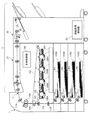
図1は、本実施の形態が適用される画像形成システムの構成を示した図である。図1に示す画像形成システムは、例えば電子写真方式によってカラー画像を形成するプリンタや複写機等の画像形成装置1と、画像形成装置1にて画像形成された後の記録材(用紙、シート)に対して綴じ等の後処理を行うシート後処理装置2(記録材処理装置の一例)とで構成される。
Embodiments of the present invention will be described below in detail with reference to the accompanying drawings.
FIG. 1 is a diagram illustrating a configuration of an image forming system to which the exemplary embodiment is applied. An image forming system shown in FIG. 1 includes, for example, an image forming apparatus 1 such as a printer or a copier that forms a color image by an electrophotographic method, and a recording material (paper, sheet) after the image is formed by the image forming apparatus 1. And a sheet post-processing apparatus 2 (an example of a recording material processing apparatus) that performs post-processing such as binding.
画像形成装置1は、所謂タンデム方式で構成され、各色画像データに基づいて画像形成を行う4つの画像形成ユニット100Y,100M,100C,100K(「画像形成ユニット100」とも総称する)、各画像形成ユニット100に設けられた感光体ドラム107を露光するレーザ露光装置101を備えている。また、画像形成装置1は、各画像形成ユニット100にて形成された各色のトナー像が多重転写される中間転写ベルト102、各画像形成ユニット100にて形成された各色トナー像を中間転写ベルト102に順次転写(一次転写)する一次転写ロール103、中間転写ベルト102上に転写された各色トナー像を記録材(用紙)に一括転写(二次転写)する二次転写ロール104、二次転写された各色トナー像を用紙上に定着する定着装置105、さらには、画像形成装置1の動作を制御する本体制御部106を備えている。ここで、画像形成ユニット100、中間転写ベルト102などは、記録材である用紙P(P1〜P4)に対し画像を形成する画像形成部として捉えることができる。
The image forming apparatus 1 is configured in a so-called tandem system, and forms four
画像形成装置1の各画像形成ユニット100では、感光体ドラム107への帯電工程、レーザ露光装置101からの走査露光による感光体ドラム107での静電潜像形成工程、形成された静電潜像への各色トナーの現像工程等を経て、各色のトナー像が形成される。各画像形成ユニット100に形成された各色トナー像は、一次転写ロール103により中間転写ベルト102上に順次静電転写される。そして、各色トナー像は、中間転写ベルト102の移動に伴って二次転写ロール104が配設された位置に向けて搬送される。
In each image forming unit 100 of the image forming apparatus 1, the charging process to the
一方、画像形成装置1には、異なるサイズや異なる紙種の複数の用紙P1〜P4(「用紙P」や「用紙束P」とも総称する)が、それぞれ用紙収容部110A〜110Dに収容されている。そして、本体制御部106により例えば用紙P1が指定された場合には、ピックアップロール111により用紙収容部110Aから用紙P1が取り出され、搬送ロール112によって1枚ずつレジストロール113の位置まで搬送される。なお本体制御部106により用紙P2〜P4が指定された場合にも、それぞれ同様である。そして、中間転写ベルト102上の各色トナー像が二次転写ロール104の配置位置に搬送されるタイミングに合わせて、レジストロール113から用紙Pが供給される。それにより、各色トナー像は、二次転写ロール104により形成された転写電界の作用によって用紙P上に一括して静電転写(二次転写)される。
On the other hand, in the image forming apparatus 1, a plurality of sheets P1 to P4 (collectively referred to as “sheet P” and “sheet bundle P”) of different sizes and types are accommodated in the
その後、各色トナー像が二次転写された用紙Pは、中間転写ベルト102から剥離されて定着装置105に搬送される。定着装置105では、熱および圧力による定着処理により各色トナー像が用紙P上に定着され、画像が形成される。そして、画像が形成された用紙Pは、搬送ロール114によって画像形成装置1の用紙排出部Tから排出され、画像形成装置1に接続されたシート後処理装置2に搬送される。
Thereafter, the paper P onto which the color toner images are secondarily transferred is peeled off from the
シート後処理装置2は、画像形成装置1の用紙排出部Tの下流側に配置され、画像が形成された用紙Pに対して穴あけや綴じ等の後処理を行う。
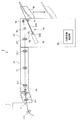
図2は、シート後処理装置2の構成を示した図である。
図2に示すように、シート後処理装置2は、画像形成装置1の用紙排出部Tに接続されたトランスポートユニット21、トランスポートユニット21に取り込まれた用紙Pに対して予め定められた後処理を施すフィニッシャユニット22、シート後処理装置2の各機構部を制御する用紙処理制御部23を備えている。ここで、用紙処理制御部23は、不図示の信号ラインで本体制御部106(図1参照)と接続され、相互に制御信号等の送受信を行う。なお、図1のシート後処理装置2では、用紙処理制御部23がフィニッシャユニット22の筐体内に設けられているが、用紙処理制御部23は画像形成装置1の筐体内に設けてもよい。また、画像形成装置1の本体制御部106が用紙処理制御部23の制御機能を備えた構成としてもよい。
The sheet
FIG. 2 is a diagram illustrating a configuration of the sheet
As shown in FIG. 2, the sheet
シート後処理装置2のトランスポートユニット21には、2穴や4穴等の穴あけ(パンチ)を施すパンチ機能部30、画像形成装置1にて画像形成された後の用紙Pをフィニッシャユニット22に向けて搬送する複数の搬送ロール211が設けられている。
In the
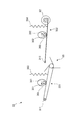
一方、フィニッシャユニット22には、水平に対し傾斜した状態で設けられ用紙Pを下方から支持するとともに用紙Pを必要枚数だけ集積させて用紙束P(記録材束の一例)を生成する用紙集積部60(記録材束生成部の一例)、トランスポートユニット21により搬送されてきた用紙Pを用紙集積部60へ送り出す送り出しロール221、ステープルを用いて用紙束Pの端部に対する綴じ処理を行う端綴じ機能部50、端綴じ機能部50により綴じ処理が行われ用紙集積部60から排出された用紙束Pが積載されるスタッカー部80が設けられている。なお、このスタッカー部80は、用紙束Pが積載されるに従い下方に向かって移動する。
On the other hand, the
またフィニッシャユニット22には、回転駆動し用紙集積部60に集積された用紙束Pをスタッカー部80に排出(搬送)する排出ロール61が設けられている。さらに、用紙Pが用紙集積部60に集積される際には排出ロール61から退避した箇所に位置し、用紙Pが用紙集積部60から搬出される際には排出ロール61に向かって移動する移動ロール62が設けられている。第2の移動部材の一例としてのこの移動ロール62は、用紙集積部60上の用紙束Pに押圧配置され、排出ロール61とともに、用紙束Pをスタッカー部80に移動させる(用紙束Pをスタッカー部80に向けて搬送する)。
Further, the
またフィニッシャユニット22には、第1回転パドル65が設けられている。この第1回転パドル65は、図中時計回り方向に回転駆動し、送り出しロール221により用紙集積部60に向けて送り出された用紙Pを、用紙集積部60の用紙規制部60Bに向けて移動させる。またフィニッシャユニット22には、第1回転パドル65よりも用紙規制部60B側に設けられ、図中時計回り方向に回転駆動し、用紙Pを用紙規制部60Bに向けて移動させる第2回転パドル66が設けられている。ここで第1回転パドル65(第2回転パドル66も同様)は、回転軸65A(図3参照)と、この回転軸65Aから突出するように設けられた複数の弾性片65Bとから構成されている。
The
なお、上記では説明を省略したが、図2に示すように、用紙集積部60には、底板60Aが設けられている。また用紙集積部60には、上記のとおり用紙規制部60Bが設けられている。ここでこの用紙規制部60Bは、底板60Aの一方の端部(端綴じ機能部50が設けられている側の端部)に設けられ、移動してくる用紙Pの端部に突き当たりこの用紙Pの移動を規制する。本実施形態では、第1回転パドル65および第2回転パドル66により移動する用紙Pがこの用紙規制部60Bに突き当たり、用紙Pの移動が規制される。これにより、用紙Pの端部の揃えが行われる。
Although not described above, as shown in FIG. 2, the
ここで本実施形態では、第1回転パドル65は、用紙集積部60に対し進退可能に設けられている。そして、送り出しロール221により1枚目の用紙Pが送り出された際、第1回転パドル65は、用紙集積部60に接近する。これにより、この1枚目の用紙Pに第1回転パドル65が接触し、この1枚目の用紙Pは用紙規制部60Bに向かって移動する。また、次に搬送されてくる2枚目の用紙Pの移動を妨げないようにするため、第1回転パドル65は、上記1枚目の用紙Pを用紙規制部60Bに向けて移動させた後、上方に向かって移動する。
Here, in the present embodiment, the
その後、第1回転パドル65は、用紙集積部60に再び接近し、上記2枚目の用紙Pを用紙規制部60Bに向けて移動させる。その後、第1回転パドル65は上方に向かって移動する。即ち、本実施形態における第1回転パドル65は、用紙Pが搬送されてくる度に、用紙集積部60への接近、用紙集積部60からの退避を行う。なお上記では説明を省略したが、本実施形態では、用紙集積部60の幅方向における両端部に、用紙Pの幅方向における用紙Pの位置を揃える幅位置揃え機構(不図示)が設けられている。これにより、用紙Pが用紙集積部60に集積されるに際し、用紙Pの幅方向における位置も揃えられる。
Thereafter, the first
用紙集積部60周辺の構造について更に詳細に説明する。
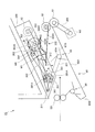
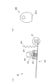
図3は、フィニッシャユニット22の上部の構成を拡大して示した図である。
上記のとおり、本実施形態では、用紙Pを必要枚数だけ集積させて用紙束Pを生成する用紙集積部60、用紙集積部60に集積された用紙束Pをスタッカー部80に排出する排出ロール61、用紙集積部60(排出ロール61)に対し進退可能に設けられた移動ロール62、送り出しロール221により送り出された用紙Pを用紙集積部60の用紙規制部60Bに向けて移動させる第1回転パドル65、第2回転パドル66が設けられている。
The structure around the
FIG. 3 is an enlarged view of the configuration of the upper portion of the
As described above, in the present embodiment, the
また、図3に示すように、フィニッシャユニット22には、装置フレーム300、装置フレーム300に固定された第1モータM1、この第1モータM1(駆動源の一例)により回転される第1回転部材301、第1モータM1により回転される第2回転部材302が設けられている。また、回転可能に設けられ第1回転部材301を支持する第1シャフト351、回転可能に設けられ第2回転部材302を支持する第2シャフト352が設けられている。
As shown in FIG. 3, the
ここで第1回転部材301は、円盤状に形成されるとともに一方の側面に突起301Aを有している。また第2回転部材302も、円盤状に形成され一方の側面に突起302Aを有している。ここで突起301Aは、第1回転部材301の回転中心から外れた箇所に設けられ、突起302Aも第2回転部材302の回転中心から外れた箇所に設けられている。またフィニッシャユニット22には、第1モータM1の駆動軸MK(駆動部の一例)から第1シャフト351へ回転駆動力を伝達する第1伝達ベルト303、第1モータM1の駆動軸MKから第2シャフト352へ回転駆動力を伝達する第2伝達ベルト304が設けられている。
Here, the first rotating
また、フィニッシャユニット22には、第1回転パドル65を支持する第1支持部材321(第1の支持部材の一例)が設けられている。この第1支持部材321は、長尺状に形成されるとともに、装置フレーム300に固定された第1回転軸311に対し一端が取り付けられ、他端に第1回転パドル65が取り付けられている。ここでこの第1支持部材321は、第1回転軸311を中心に回転(揺動)できるようになっている。なお、上記では説明を省略したが、本実施形態では、第1回転軸311が回転駆動するとともに、第1回転軸311からの回転駆動力を第1回転パドル65に伝達し第1回転パドル65を回転させる伝達ベルト(不図示)が設けられている。
Further, the
また本実施形態では、移動ロール62を支持する第2支持部材322(第2の支持部材の一例)が設けられている。この第2支持部材322は、上記第1支持部材321と同様に長尺状に形成され、装置フレーム300に固定された第2回転軸312に一端が取り付けられ、他端に移動ロール62が取り付けられている。また、この第2支持部材322は、第2回転軸312を中心に回転(揺動)できるようになっている。
In the present embodiment, a second support member 322 (an example of a second support member) that supports the moving
第1回転部材301は、第1支持部材321のうちの一端と他端との間に位置する部位に対峙可能に設けられている。また本実施形態では、第1支持部材321のうちの第1回転部材301と対峙する箇所に貫通孔321Aが形成されており、第1回転部材301に設けられた突起301Aが、この貫通孔321Aの内部に配置されている。このため本実施形態では、第1回転部材301の回転に応じ、第1支持部材321が第1回転軸311を中心として回転(揺動)するようになっている。そしてこの回転によって、第1回転パドル65が用紙集積部60に対し進退するようになっている。
The
また第2回転部材302は、第2支持部材322のうちの一端と他端との間に位置する部位に対峙可能に設けられている。さらに本実施形態の第2支持部材322は、移動ロール62と第2回転軸312とを接続する本体322A、一端がこの本体322Aに接続されるとともに本体322Aとの間に間隙を有して配置され且つ本体322Aに対向して配置された第1対向片322B、一端がこの第1対向片322Bに接続されるとともに第1対向片322Bとの間に間隙を有して配置され且つ第1対向片322Bに対向して配置された第2対向片322Cとから構成されている。
Further, the second rotating
そして本実施形態では、第1対向片322Bと第2対向片322Cとの間に、第2回転部材302に設けられた突起302Aが配置されている。そして本実施形態では、このように第1対向片322Bと第2対向片322Cとの間に突起302Aが配置された結果、第2回転部材302の回転に応じ、第2支持部材322が第2回転軸312を中心として回転(揺動)する。そしてこの回転によって、移動ロール62が用紙集積部60(排出ロール61)に対し進退する。なお用紙集積部60には、50枚など多くの用紙Pが積載可能である。本実施形態では、このように多くの用紙Pが用紙集積部60に積載された状態にて、移動ロール62が用紙P(用紙束P)に圧接される場合、第2支持部材322の本体322Aや第1対向片322Bが撓むようになっている。
In the present embodiment, a
また本実施形態では、フィニッシャユニット22に、排出ロール61を回転駆動する第2モータM2と、第2モータM2からの回転駆動力を排出ロール61に伝達する第3伝達ベルト305が設けられている。また本実施形態では、第1シャフト351と第1回転部材301との間に第1ワンウェイクラッチ361が設けられ、第2シャフト352と第2回転部材302との間に第2ワンウェイクラッチ362が設けられている。ここで本実施形態では、第1ワンウェイクラッチ361によって、第1シャフト351が反時計回り方向(図中矢印A方向)に回転した場合に、第1シャフト351に追従して第1回転部材301が反時計回り方向に回転するようになっている。また、第1シャフト351が時計回り方向に回転した場合に、第1シャフト351に第1回転部材301が追従せず、第1シャフト351のみが回転するようになっている。
In the present embodiment, the
また、第2ワンウェイクラッチ362によって、本実施形態では、第2シャフト352が時計回り方向(図中矢印B方向)に回転した場合に、第2シャフト352に追従して第2回転部材302が回転するようになっている。一方で、第2シャフト352が反時計回り方向に回転した場合には、第2シャフト352に第2回転部材302が追従せず、第2シャフト352のみが回転するようになっている。
このため本実施形態では、第1モータM1の駆動軸MKが図中時計回り方向に回転した場合に、第2回転部材302が時計回り方向に回転し、移動ロール62の用紙集積部60に対する進退が行われる。その一方で、駆動軸MKが図中反時計回り方向に回転した場合には、第1回転部材301が反時計回り方向に回転し、第1回転パドル65の用紙集積部60に対する進退が行われる。
In the present embodiment, the second one-
For this reason, in this embodiment, when the drive shaft MK of the first motor M1 rotates in the clockwise direction in the drawing, the second rotating
なお、本実施形態における第1回転部材301、第1支持部材321、および第1回転軸311は、第1の移動部材の一例としての第1回転パドル65の進退を行う第1の進退機構として捉えることができる。また、第2回転部材302、第2支持部材322、および第2回転軸312は、第2の移動部材として機能する移動ロール62の進退を行う第2の進退機構として捉えることができる。また、第1伝達ベルト303、第1シャフト351、第1ワンウェイクラッチ361、第2伝達ベルト304、第2シャフト352、および第2ワンウェイクラッチ362は、第1モータM1の駆動軸MKが一方向へ駆動した場合にこの駆動軸MKからの駆動力を上記第1の進退機構に伝達し、駆動軸MKが反対方向へ駆動した場合にこの駆動軸MKからの駆動力を上記第2の進退機構に伝達する伝達機構として捉えることができる。
In addition, the
また、第1伝達ベルト303、第1シャフト351、および第1ワンウェイクラッチ361は、第1モータM1の駆動軸MKが一方向へ駆動した場合にこの駆動軸MKからの駆動力を上記第1の進退機構に伝達し、駆動軸MKが反対方向へ駆動した場合には第1の進退機構への駆動力の伝達を行わない第1の伝達機構として捉えることができる。また、第2伝達ベルト304、第2シャフト352、および第2ワンウェイクラッチ362は、第1モータM1の駆動軸MKが上記反対方向へ駆動した場合にこの駆動軸MKからの駆動力を上記第2の進退機構に伝達し、駆動軸MKが上記一方向へ駆動した場合には第2の進退機構への駆動力の伝達を行わない第2の伝達機構として捉えることができる。
Further, the
ここで、用紙集積部60に用紙Pが集積される際の各部の動作について説明する。
用紙集積部60に用紙Pが集積される際には、まず、送り出しロール221によって用紙集積部60に対し用紙Pが順次送り出される。この際、第1モータM1の駆動軸MKが反時計回り方向に回転する。これによって、第1回転パドル65が用紙集積部60に対し進退し、順次搬送されてくる用紙Pが用紙規制部60Bに向かって移動していく。そして順次搬送されてきた用紙Pのうちの最後の用紙Pが第1回転パドル65によって用紙規制部60Bに向けて送り出され、且つ、第1回転パドル65が上方に移動した後に(用紙束Pから退避した後)に、第1モータM1の逆転が開始される。なお本実施形態では、上記最後の用紙Pが第1回転パドル65によって用紙規制部60Bに向けて送り出された後、端綴じ機能部50による綴じ処理が行われる。これにより、用紙集積部60上に綴じ処理が施された用紙束Pが生成される。
Here, the operation of each unit when the paper P is stacked on the
When the paper P is stacked on the
その後、本実施形態では、第1モータM1が上記のように逆転されることで、第2回転部材302の回転が開始され、移動ロール62が用紙集積部60上の用紙束Pに向かって移動していく。その後、第1モータM1の回転が一旦停止される。これにより用紙束Pが排出ロール61と移動ロール62とにより押圧された状態となる。その後、第2モータM2の回転が開始され、用紙束Pのスタッカー部80への排出が行われる。次いで、第1モータM1の駆動が予め定められた時間行われ、移動ロール62が用紙集積部60から離れる方向に向かって移動する。その後、本実施形態では、第1モータM1の逆転が行われ、新たに搬送されてくる用紙Pが第1回転パドル65によって用紙規制部60Bに向かって移動していく。
Thereafter, in the present embodiment, when the first motor M1 is reversed as described above, the rotation of the second rotating
このように、本実施形態における構成では、2つのモータではなく、1つのモータ(第1モータM1)によって、第1回転パドル65の進退および移動ロール62の進退が可能となっている。なお、モータなどの駆動源を2つ設け、第1回転パドル65の進退および移動ロール62の進退をそれぞれ個別に行うこともできるが、この場合、コストの増加や装置の大型化を招いてしまう。
As described above, in the configuration of the present embodiment, the
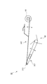
なお上記では、第1支持部材321の一端を支持する第1回転軸311、第2支持部材322の一端を支持する第2回転軸312の、2つの支持軸が設けられた構成を説明したが、図4(フィニッシャユニット22の他の構成例を示した図)に示すように、第1支持部材321および第2支持部材322を一つの(共通の)回転軸313により支持するようにしてもよい。図3にて示した第2回転軸312には、移動ロール62が用紙束Pを押圧した際の反力を支持するための剛性を付与する必要があり、第1回転軸311には、第1回転パドル65に回転駆動力を伝達するための機構を設ける必要がある。そしてこのように、複数の機能を複数の異なる回転軸に分けて設ける場合、コストが増加しやすくなる。一方で、図4に示したように回転軸の共用化を図った場合には、コストの増加が抑制される。
In the above description, the configuration in which the two support shafts are provided, that is, the
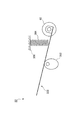
図5は、フィニッシャユニット22の他の構成例を示した図である。なお、上記にて説明した機能と同様の機能については、同様の符号を用いここではその説明を省略する。
図5に示すフィニッシャユニット22では、上記第1回転部材301に替えて第1カム381が設けられている。また上記第2回転部材302に替えて第2カム382が設けられている。さらに、第1支持部材321を上方(第1カム381)に向けて付勢する第1スプリング383(付勢部材の一例)と、第2支持部材322を上方(第2カム382)に向けて付勢する第2スプリング384(付勢部材の一例)とが設けられている。なお、上記と同様、第1シャフト351と第1カム381との間には第1ワンウェイクラッチ361が設けられ、第2シャフト352と第2カム382との間には第2ワンウェイクラッチ362が設けられている。
FIG. 5 is a diagram illustrating another configuration example of the
In the
ここで図5に示した実施形態の動作について説明する。
図5に示す構成では、送り出しロール221(図2参照)によって用紙集積部60に対し用紙Pが順次送り出される際、上記と同様、第1モータM1の駆動軸MKが反時計回り方向に回転する。これにより、第1シャフト351(軸の一例)の回転に追従して第1カム381が反時計回り方向に回転し、第1回転パドル65の用紙集積部60に対する進退が繰り返される。これにより、送り出しロール221によって送り出された用紙Pが用紙規制部60Bに向かって移動し、用紙Pの揃えが行われるとともに、用紙集積部60に用紙束Pが生成される。なお、上記と同様、用紙束Pを構成する用紙Pのうちの最後の用紙Pが第1回転パドル65により用紙規制部60Bに送り出された後、第1回転パドル65は上方へ退避する。
Here, the operation of the embodiment shown in FIG. 5 will be described.
In the configuration shown in FIG. 5, when the paper P is sequentially sent out to the
その後、第1回転パドル65が上方へ退避している状態にて、第1モータM1の逆転が開始され、予め定められた時間が経過した後、この逆転が停止される。これにより、移動ロール62が用紙束Pに向かって進出するとともに、移動ロール62が用紙束Pに接触する。その後、排出ロール61の回転がなされ、スタッカー部80への用紙束Pの排出が行われる。そしてこの排出が行われると、第1モータM1の回転が再びなされ移動ロール62が用紙集積部60から退避する。その後、第1モータM1の逆転がなされ、第1回転パドル65の用紙集積部60に対する進退が再び行われる。
Thereafter, in a state where the first
なお本実施形態では、上記のように、第1カム381と第1シャフト351との間に第1ワンウェイクラッチ361が設けられている。このため、本実施形態では、第1カム381に外力が作用し反時計回り方向に第1カム381が回転した際、この第1カム381は第1シャフト351に対し空回りするようになる。この結果、本実施形態では、第1カム381が下死点を通過した際、第1スプリング383から作用する荷重によって(第1カム381が第1支持部材321により下方から押圧されることによって)、第1カム381が回転するようになる。付言すると、第1モータM1によらず第1スプリング383によって、第1カム381が回転するようになる。そしてこの回転により、第1回転パドル65が上方へ退避する。即ち図5に示す構成では、第1回転パドル65の上方への退避が第1スプリング383により行われるようになっている。
In the present embodiment, as described above, the first one-
ここでこのように第1モータM1によらず第1スプリング383によって第1回転パドル65が上方へ退避する場合、第1カム381が下死点を通過した後に、第1モータM1の逆転(移動ロール62の用紙集積部60への進出)を行うことができるようになる。そしてこの場合、用紙束Pがスタッカー部80に向けて排出されるタイミングを、図3で示した構成よりも早めることができるようになる。図3に示した構成では、第1回転パドル65の上方への退避を第1モータM1だけで行っているため、第1回転パドル65の上方への退避が終了するまで、第1モータM1の駆動を継続する必要がある。そしてこの後に、第1モータM1を逆転させ、移動ロール62の進出、スタッカー部80への用紙束Pの排出を行うことになる。
Here, when the first
なお第2カム382側も同様であり、第2カム382が下死点を通過した際、第2スプリング384から作用する荷重によって、第2カム382は回転する。付言すると、この場合も、第1モータM1によらず第2スプリング384によって、第2カム382が回転する。そしてこの回転により、移動ロール62が上方へ退避する。
The same applies to the
ここでこのように、第1モータM1によらず第2スプリング384によって移動ロール62が上方へ退避する場合、上記と同様、第2カム382が下死点を通過した後に、第1モータM1の逆転(第1回転パドル65の用紙集積部60への進出)を行うことができるようになる。そしてこの場合は、用紙集積部60への用紙Pの排出が可能となるタイミングを、図3で示した構成よりも早めることができるようになる。図3に示した構成では、移動ロール62の上方への退避を第1モータM1だけで行っているため、移動ロール62の上方への退避が終了するまで、第1モータM1の駆動を継続する必要が生じる。そしてこの後に、第1モータM1を逆転させ、第1回転パドル65の進出を行うことになる。
Here, when the moving
ところで、用紙集積部60には、数枚のみならず50枚など多くの用紙Pが集積される。ここで図3に示した構成では、このように多数の用紙Pが集積された際、第2支持部材322の本体322Aや第1対向片322Bが撓むようになっている。これにより、多くの用紙Pが集積される場合であっても、移動ロール62が用紙束Pの厚みに応じて変位し、用紙束Pが、移動ロール62および排出ロール61により挟まれるようになる。
By the way, not only several sheets but also many sheets P such as 50 sheets are stacked on the
ところで、図5に示した構成では、第2支持部材322のうちの移動ロール62に近い側の位置する部位が第2カム382により押圧されるようになっており、第2支持部材322に撓みが生じにくい状態となっている。そしてこの場合、多数の用紙Pを、移動ロール62と排出ロール61とにより挟むことが困難となるおそれがある。より詳細に説明すると、移動ロール62と排出ロール61とによりこの多数の用紙Pを挟むことは一応可能となるが、上記下死点まで第2カム382が回転することができず、予め定められた荷重でこの多数の用束Pを挟むことが困難となるおそれがある。そしてこの場合、用紙束Pの排出がなされる際、用紙束Pと排出ロール61との間で滑りが生じ、用紙束Pのスタッカー部80への排出がなされない事態が起こりうる。
By the way, in the configuration shown in FIG. 5, a portion of the
このような不具合の発生を抑制するため、例えば、図6(第2カム382の周辺の構造を示した図)の(A)に示すように、第2カム382と第2支持部材322との間に、コイルスプリング、板ばね、ゴムなどにより構成される弾性部材400を設けることができる。このように弾性部材400を設けた場合、上記下死点まで第2カム382が回転するようになり、予め定められた荷重で用紙束Pが押圧されるようになる。これにより、用紙束Pのスタッカー部80への排出がより確実になされるようになる。ここで、第2カム382のうち、第2カム382が下死点に位置する際に第2支持部材322側に接触する部位には、図6(B)に示すように、平坦面382Aを設けておくことが好ましい。
In order to suppress the occurrence of such a problem, for example, as shown in FIG. 6A (a diagram showing the structure around the second cam 382), the
なお第2支持部材322や第2カム382は、図7(フィニッシャユニット22の他の構成例を示した図)に示すように設けることもできる。より具体的に説明すると、第2カム382を第2支持部材322の上方ではなく下方に設け、第2スプリング384により上方から押圧される第2支持部材322を下方から支持する構成とすることもできる。
The
ところで、図7に示した構成では、移動ロール62を排出ロール61から離れる方向に移動させる際、第2スプリング384から作用する力に抗して移動ロール62を移動させるため、移動ロール62が移動しにくい状態となる。そしてこのように移動ロール62が移動しにくくなると、移動ロール62と排出ロール61との間の間隙を拡げるのが困難となりやすい。付言すると、移動ロール62と排出ロール61との間の間隙が小さいものとなりやすい。そしてこの場合、カール(反り)などが生じている用紙Pが搬送されてきた際に、この用紙Pが移動ロール62などに引っ掛かりやすくなる。なお上記では説明を省略したが、用紙集積部60に用紙Pが集積される際、用紙Pは移動ロール62と排出ロール61との間を一旦通過する。その後、この用紙Pは用紙規制部60Bに向かって移動していく。上記のように用紙Pが移動ロール62などに引っ掛かりやすくなると、用紙Pの用紙規制部60Bへの移動などが規制され、用紙集積部60における用紙束Pの生成が困難となる。
By the way, in the configuration shown in FIG. 7, when moving the moving
その一方で、図5に示した構成は、移動ロール62を排出ロール61から離れる方向に移動させる際、第2スプリング384から作用する力に抗して移動ロール62を移動させる構成ではないため、移動ロール62が移動しやすくなっている。このため図5に示す構成では、図7に示した構成に比べ、移動ロール62と排出ロール61との間の間隙を拡げやすくなっている。そしてこの場合、カールなどが発生している用紙Pであっても、移動ロール62と排出ロール61との間を通過しやすくなる。
なお、図5に示す構成では、移動ロール62が上方に退避した状態にて、移動ロール62と排出ロール61との離間距離は、本フィニッシャユニット22にて処理可能な用紙束Pの最大厚さの2倍以上に設定されている。
On the other hand, the configuration shown in FIG. 5 is not configured to move the moving
In the configuration shown in FIG. 5, the separation distance between the moving
60…用紙集積部、62…移動ロール、65…第1回転パドル、100…画像形成ユニット、102…中間転写ベルト、301…第1回転部材、302…第2回転部材、303…第1伝達ベルト、304…第2伝達ベルト、311…第1回転軸、312…第2回転軸、321…第1支持部材、322…第2支持部材、351…第1シャフト、352…第2シャフト、361…第1ワンウェイクラッチ、362…第2ワンウェイクラッチ、381…第1カム、382…第2カム、383…第1スプリング、384…第2スプリング、M1…第1モータ
DESCRIPTION OF
Claims (9)
前記記録材束生成部に対し進退可能に設けられ、当該記録材束生成部に記録材が搬送されてきた際に当該記録材束生成部に接近するとともに、当該記録材束生成部の予め定められた箇所に向けて当該記録材を移動させる第1の移動部材と、
前記第1の移動部材の前記進退を行う第1の進退機構と、
前記記録材束生成部に対し進退可能に設けられ、当該記録材束生成部にて生成された記録材束の搬送に用いられる第2の移動部材と、
前記第2の移動部材の前記進退を行う第2の進退機構と、
一方向および反対方向への駆動が可能に設けられた駆動部を有した駆動源と、
前記駆動部が前記一方向へ駆動した場合に当該駆動部からの駆動力を前記第1の進退機構に伝達し、当該駆動部が前記反対方向へ駆動した場合に当該駆動部からの駆動力を前記第2の進退機構に伝達する伝達機構と、
備える記録材処理装置。 A recording material bundle generator for generating a recording material bundle;
The recording material bundle generation unit is provided so as to be capable of advancing and retreating. When the recording material is conveyed to the recording material bundle generation unit, the recording material bundle generation unit approaches the recording material bundle generation unit, and the recording material bundle generation unit determines in advance. A first moving member that moves the recording material toward the given location;
A first advancing and retracting mechanism for performing the advancing and retreating of the first moving member;
A second moving member that is provided so as to be capable of advancing and retreating with respect to the recording material bundle generation unit, and is used for conveying the recording material bundle generated by the recording material bundle generation unit;
A second advancing and retracting mechanism for performing the advancing and retreating of the second moving member;
A drive source having a drive unit provided to be able to drive in one direction and in the opposite direction;
When the driving unit is driven in the one direction, the driving force from the driving unit is transmitted to the first advancing / retreating mechanism, and when the driving unit is driven in the opposite direction, the driving force from the driving unit is transmitted. A transmission mechanism for transmitting to the second advance / retreat mechanism;
A recording material processing apparatus provided.
前記第1の支持部材の揺動が可能なように当該第1の支持部材を支持する支持軸と、
揺動可能に設けられ、前記第2の移動部材を支持する第2の支持部材と、
を更に備え、
前記第2の支持部材は、前記第1の支持部材を支持する前記支持軸によって支持されていることを特徴とする請求項1記載の記録材処理装置。 A first support member for supporting the first moving member;
A support shaft that supports the first support member so that the first support member can swing;
A second support member provided so as to be swingable and supporting the second moving member;
Further comprising
The recording material processing apparatus according to claim 1, wherein the second support member is supported by the support shaft that supports the first support member.
前記記録材束生成部から離れる方向への前記第2の移動部材の移動は、前記付勢部材により行われることを特徴とする請求項4記載の記録材処理装置。 The cam of the second advance / retreat mechanism is provided on a side farther from the recording material bundle generating unit than the support member supporting the second moving member, and the support member of the second advance / retreat mechanism is The biasing member is biased toward the direction away from the recording material bundle generating unit,
5. The recording material processing apparatus according to claim 4, wherein the movement of the second moving member in a direction away from the recording material bundle generating unit is performed by the biasing member.
前記画像形成部により画像が形成された記録材を集積し記録材束を生成する記録材束生成部と、
前記記録材束生成部に対し進退可能に設けられ、当該記録材束生成部に対して前記画像形成部から記録材が搬送されてきた際に当該記録材束生成部に接近するとともに、当該記録材束生成部の予め定められた箇所に向けて当該記録材を移動させる第1の移動部材と、
前記第1の移動部材の前記進退を行う第1の進退機構と、
前記記録材束生成部に対し進退可能に設けられ、当該記録材束生成部にて生成された記録材束の搬送に用いられる第2の移動部材と、
前記第2の移動部材の前記進退を行う第2の進退機構と、
一方向および反対方向への駆動が可能に設けられた駆動部を有した駆動源と、
前記駆動部が前記一方向へ駆動した場合に当該駆動部からの駆動力を前記第1の進退機構に伝達し当該駆動部が前記反対方向へ駆動した場合には当該第1の進退機構への当該駆動力の当該伝達を行わない第1の伝達機構と、
前記駆動部が前記反対方向へ駆動した場合に当該駆動部からの駆動力を前記第2の進退機構に伝達し当該駆動部が前記一方向へ駆動した場合には当該第2の進退機構への当該駆動力の当該伝達を行わない第2の伝達機構と、
を備える画像形成システム。 An image forming unit for forming an image on a recording material;
A recording material bundle generating unit that accumulates recording materials on which images are formed by the image forming unit and generates a recording material bundle;
The recording material bundle generation unit is provided so as to be able to advance and retreat. When the recording material is conveyed from the image forming unit to the recording material bundle generation unit, the recording material bundle generation unit approaches the recording material bundle generation unit, and the recording material bundle generation unit A first moving member that moves the recording material toward a predetermined position of the material bundle generation unit;
A first advancing and retracting mechanism for performing the advancing and retreating of the first moving member;
A second moving member that is provided so as to be capable of advancing and retreating with respect to the recording material bundle generation unit, and is used for conveying the recording material bundle generated by the recording material bundle generation unit;
A second advancing and retracting mechanism for performing the advancing and retreating of the second moving member;
A drive source having a drive unit provided to be able to drive in one direction and in the opposite direction;
When the drive unit is driven in the one direction, the driving force from the drive unit is transmitted to the first advance / retreat mechanism, and when the drive unit is driven in the opposite direction, the drive to the first advance / retreat mechanism is performed. A first transmission mechanism that does not transmit the driving force;
When the driving unit is driven in the opposite direction, the driving force from the driving unit is transmitted to the second advancing / retreating mechanism, and when the driving unit is driven in the one direction, the driving force to the second advancing / retreating mechanism is transmitted. A second transmission mechanism that does not transmit the driving force;
An image forming system comprising:
前記第1の進退機構の前記カムは、予め定められた軸を中心として回転可能に設けられ、前記一方向に回転する当該軸に追従して当該一方向への前記回転を行うとともに、当該軸に対する回転であって当該一方向への回転が可能に設けられていることを特徴とする請求項7記載の画像形成システム。 The first advancing / retracting mechanism includes a support member that supports the first moving member, a cam that receives the driving force transmitted by the first transmission mechanism, rotates in one direction, and displaces the support member; The biasing member that biases the support member to the cam performs the advance and retreat of the first moving member,
The cam of the first advancing / retracting mechanism is provided rotatably about a predetermined axis, follows the axis rotating in the one direction, performs the rotation in the one direction, and The image forming system according to claim 7, wherein the image forming system is provided so as to be capable of rotating in one direction.
前記第2の進退機構の前記カムは、予め定められた軸を中心として回転可能に設けられ、前記一方向に回転する当該軸に追従して当該一方向への前記回転を行うとともに、当該軸に対する回転であって当該一方向への回転が可能に設けられていることを特徴とする請求項7又は8に記載の画像形成システム。 The second advancing / retracting mechanism includes a support member that supports the second moving member, a cam that receives the driving force transmitted by the second transmission mechanism, rotates in one direction, and displaces the support member; The advancing and retreating of the second moving member is performed by a biasing member that biases the support member to the cam,
The cam of the second advancing / retreating mechanism is provided to be rotatable around a predetermined axis, follows the axis rotating in the one direction, performs the rotation in the one direction, and The image forming system according to claim 7, wherein the image forming system is provided so as to be capable of rotating in one direction.
Priority Applications (1)
| Application Number | Priority Date | Filing Date | Title |
|---|---|---|---|
| JP2011005433A JP2012144356A (en) | 2011-01-14 | 2011-01-14 | Recording material processing apparatus and image forming system |
Applications Claiming Priority (1)
| Application Number | Priority Date | Filing Date | Title |
|---|---|---|---|
| JP2011005433A JP2012144356A (en) | 2011-01-14 | 2011-01-14 | Recording material processing apparatus and image forming system |
Publications (1)
| Publication Number | Publication Date |
|---|---|
| JP2012144356A true JP2012144356A (en) | 2012-08-02 |
Family
ID=46788352
Family Applications (1)
| Application Number | Title | Priority Date | Filing Date |
|---|---|---|---|
| JP2011005433A Pending JP2012144356A (en) | 2011-01-14 | 2011-01-14 | Recording material processing apparatus and image forming system |
Country Status (1)
| Country | Link |
|---|---|
| JP (1) | JP2012144356A (en) |
Cited By (1)
| Publication number | Priority date | Publication date | Assignee | Title |
|---|---|---|---|---|
| JP2018034973A (en) * | 2016-09-01 | 2018-03-08 | 富士ゼロックス株式会社 | Post-processing device |
-
2011
- 2011-01-14 JP JP2011005433A patent/JP2012144356A/en active Pending
Cited By (1)
| Publication number | Priority date | Publication date | Assignee | Title |
|---|---|---|---|---|
| JP2018034973A (en) * | 2016-09-01 | 2018-03-08 | 富士ゼロックス株式会社 | Post-processing device |
Similar Documents
| Publication | Publication Date | Title |
|---|---|---|
| US9415560B2 (en) | Sheet processing apparatus, image forming system, and image forming apparatus | |
| CN102367105B (en) | Sheet feeding apparatus and image forming apparatus | |
| JP5533122B2 (en) | Recording material processing apparatus and image forming system | |
| US11613439B2 (en) | Sheet feeding apparatus and image forming apparatus | |
| JP2011201669A (en) | Image forming system and recording material postprocessing device | |
| US10156824B2 (en) | Binding device including a reduction part | |
| US9403655B2 (en) | Post-processing device having shifted sheets | |
| JP2014056279A (en) | Image forming system and recording material post-processing device | |
| JP2012144356A (en) | Recording material processing apparatus and image forming system | |
| JP2009190885A (en) | Sheet feeding apparatus and image forming apparatus | |
| JP2014240986A (en) | Fixing member and image forming apparatus including the same | |
| JP2011201652A (en) | Recording material processing device and image forming system | |
| JP2012041134A (en) | Post-processing device and image forming system | |
| JP6759808B2 (en) | Recording material processing equipment and image formation system | |
| JP2017081665A (en) | Post-processing device and image formation apparatus | |
| US7552926B2 (en) | Sheet transportation device and printer comprising a device of this kind | |
| JP4208609B2 (en) | Sheet stacking alignment device | |
| JP4054627B2 (en) | Sheet processing apparatus and image forming apparatus | |
| JP5605201B2 (en) | Paper post-processing apparatus and image forming apparatus | |
| JP4055067B2 (en) | Paper feeding device and image forming apparatus | |
| JP5440185B2 (en) | Paper discharging apparatus, post-processing apparatus, image forming apparatus, and image forming system | |
| JP6245868B2 (en) | Sheet conveying apparatus and image forming apparatus | |
| JP2013124175A (en) | Image forming apparatus | |
| JP6759807B2 (en) | Recording material processing equipment and image formation system | |
| JPH0826505A (en) | Paper feeder |