JP2012144171A - Controller for hybrid vehicle - Google Patents
Controller for hybrid vehicle Download PDFInfo
- Publication number
- JP2012144171A JP2012144171A JP2011004663A JP2011004663A JP2012144171A JP 2012144171 A JP2012144171 A JP 2012144171A JP 2011004663 A JP2011004663 A JP 2011004663A JP 2011004663 A JP2011004663 A JP 2011004663A JP 2012144171 A JP2012144171 A JP 2012144171A
- Authority
- JP
- Japan
- Prior art keywords
- engine
- torque
- clutch
- ecu
- electrical machine
- Prior art date
- Legal status (The legal status is an assumption and is not a legal conclusion. Google has not performed a legal analysis and makes no representation as to the accuracy of the status listed.)
- Granted
Links
Images


Classifications
-
- Y—GENERAL TAGGING OF NEW TECHNOLOGICAL DEVELOPMENTS; GENERAL TAGGING OF CROSS-SECTIONAL TECHNOLOGIES SPANNING OVER SEVERAL SECTIONS OF THE IPC; TECHNICAL SUBJECTS COVERED BY FORMER USPC CROSS-REFERENCE ART COLLECTIONS [XRACs] AND DIGESTS
- Y02—TECHNOLOGIES OR APPLICATIONS FOR MITIGATION OR ADAPTATION AGAINST CLIMATE CHANGE
- Y02T—CLIMATE CHANGE MITIGATION TECHNOLOGIES RELATED TO TRANSPORTATION
- Y02T10/00—Road transport of goods or passengers
- Y02T10/60—Other road transportation technologies with climate change mitigation effect
- Y02T10/62—Hybrid vehicles
Landscapes
- Electric Propulsion And Braking For Vehicles (AREA)
- Hybrid Electric Vehicles (AREA)
- Control Of Driving Devices And Active Controlling Of Vehicle (AREA)
- Control Of Vehicle Engines Or Engines For Specific Uses (AREA)
Abstract
【課題】エンジンが逆回転するのを抑制することが可能なハイブリッド車両の制御装置を提供する。
【解決手段】ハイブリッド車両の制御装置は、エンジンと、第1回転電機と、第2回転電機と、動力伝達機構と、クラッチ同期制御手段と、トルク制御手段と、を備える。動力伝達機構は、相互に差動回転可能な複数の回転要素を備える。クラッチ同期制御手段は、第1走行モードから、第2走行モードへ走行モードを切り替える場合、エンジンの始動前に、第1回転電機のトルクに基づきクラッチ同期制御を行う。トルク制限手段は、クラッチ同期制御中に、エンジンに伝達される第1回転電機のトルクが、エンジンの摩擦トルク以下になるように制限する。
【選択図】図4A control device for a hybrid vehicle capable of suppressing reverse rotation of an engine is provided.
A control device for a hybrid vehicle includes an engine, a first rotating electrical machine, a second rotating electrical machine, a power transmission mechanism, a clutch synchronization control unit, and a torque control unit. The power transmission mechanism includes a plurality of rotating elements that are differentially rotatable with respect to each other. The clutch synchronization control means performs clutch synchronization control based on the torque of the first rotating electrical machine before starting the engine when the travel mode is switched from the first travel mode to the second travel mode. The torque limiting means limits the torque of the first rotating electric machine transmitted to the engine to be equal to or lower than the friction torque of the engine during the clutch synchronization control.
[Selection] Figure 4
Description
本発明は、ハイブリッド車両に好適な制御装置に関する。 The present invention relates to a control device suitable for a hybrid vehicle.
従来から、内燃機関(エンジン)に加えて、発電機として主に機能する第1回転電機と、駆動輪に連結された駆動軸に動力を供給する電動機として主に機能する第2回転電機と、内燃機関の出力トルクを第1回転電機側と駆動軸及び第2回転電機側とに分配する動力分配機構を備えるハイブリッド車両が知られている。例えば、特許文献1には、エンジンと第1及び第2回転電機とを備えるとともに、第2回転電機とエンジンとの結合状態をクラッチにより切り替え可能なハイブリッド車両が開示されている。このハイブリッド車両は、クラッチの締結時には所謂シリーズパラレル式のハイブリッド走行を行い、クラッチを解放することで、エンジンを切り離して第2回転電機によるEV(Electric Vehicle)走行を行う。
Conventionally, in addition to the internal combustion engine (engine), a first rotating electrical machine that mainly functions as a generator, and a second rotating electrical machine that mainly functions as an electric motor that supplies power to a drive shaft connected to drive wheels; There is known a hybrid vehicle including a power distribution mechanism that distributes output torque of an internal combustion engine to a first rotating electrical machine side, a drive shaft, and a second rotating electrical machine side. For example,
また、特許文献2には、EV走行中に自動変速機による変速で動力分配機構に伝達されるイナーシャトルクによりエンジンが回転することを防止するため、第1回転電機を制御してエンジンの回転変動を防止する技術が開示されている。さらに、特許文献3には、エンジンの回転抵抗が所定の回転抵抗下限値以下である場合には、エンジンの逆回転を抑制するため、EV走行を規制又は禁止する制御を行う技術が開示されている。 Further, in Patent Document 2, in order to prevent the engine from rotating due to the inertia torque transmitted to the power distribution mechanism by the shift by the automatic transmission during EV traveling, the first rotating electrical machine is controlled to change the rotational speed of the engine. A technique for preventing the above is disclosed. Furthermore, Patent Document 3 discloses a technique for performing control for restricting or prohibiting EV traveling in order to suppress reverse rotation of the engine when the rotational resistance of the engine is equal to or lower than a predetermined rotational resistance lower limit value. Yes.
第2回転電機とエンジンとの結合状態をクラッチにより切り替え可能なハイブリッド車両において、クラッチが解放状態にあるEV走行からクラッチを係合させてエンジンを始動させる場合であって、第1回転電機によりクラッチの係合要素の回転を同期させる際に、エンジンに伝達される第1回転電機のトルクに起因してエンジンが逆回転する可能性がある。 In a hybrid vehicle in which the coupling state between the second rotating electrical machine and the engine can be switched by a clutch, the engine is started by engaging the clutch from EV traveling in which the clutch is in a released state, and the clutch is operated by the first rotating electrical machine. When synchronizing the rotations of the engagement elements, there is a possibility that the engine rotates reversely due to the torque of the first rotating electrical machine transmitted to the engine.
本発明は、上記のような課題を解決するためになされたものであり、エンジンが逆回転するのを抑制することが可能なハイブリッド車両の制御装置を提供することを課題とする。 The present invention has been made to solve the above-described problems, and an object of the present invention is to provide a hybrid vehicle control device capable of suppressing reverse rotation of the engine.
本発明の1つの観点では、エンジンと、第1回転電機と、第2回転電機と、前記第1回転電機に連結された第1回転要素と、前記第2回転電機と駆動軸とにクラッチを介して連結する第2回転要素と、前記エンジンと連結する第3回転要素と、を含む相互に差動回転可能な複数の回転要素を備えた動力伝達機構と、前記クラッチを解放状態にし、前記エンジンを停止させて前記第2回転電機により走行を行う第1走行モードから、前記クラッチを係合状態にし、前記エンジンを駆動させて走行を行う第2走行モードへ走行モードを切り替える場合、前記エンジンの始動前に前記第1回転電機のトルクに基づき前記クラッチの係合要素の回転を同期させる制御を行うクラッチ同期制御手段と、前記クラッチ同期制御手段が、前記制御を実行している場合、前記エンジンに伝達される前記第1回転電機のトルクが、前記エンジンの摩擦トルク以下になるように制限するトルク制限手段と、を備える。 In one aspect of the present invention, the engine, the first rotating electrical machine, the second rotating electrical machine, the first rotating element coupled to the first rotating electrical machine, the second rotating electrical machine, and the drive shaft are clutched. A power transmission mechanism comprising a plurality of rotating elements that are differentially rotatable with each other, including a second rotating element that is coupled to the engine, and a third rotating element that is coupled to the engine, and the clutch is released, When the travel mode is switched from the first travel mode in which the engine is stopped and the second rotating electrical machine travels to the second travel mode in which the clutch is engaged and the engine is driven to travel. A clutch synchronization control means for performing a control to synchronize the rotation of the engagement element of the clutch based on the torque of the first rotating electrical machine before starting, and the clutch synchronization control means executes the control. That case, the torque of the first rotating electric machine is transmitted to the engine, and a torque limiting means for limiting to be less than the friction torque of the engine.
上記のハイブリッド車両の制御装置は、ハイブリッド車両に搭載され、エンジンと、第1回転電機と、第2回転電機と、動力伝達機構と、クラッチ同期制御手段と、トルク制御手段と、を備える。動力伝達機構は、相互に差動回転可能な複数の回転要素を備える。具体的には、動力伝達機構は、第1回転電機に連結された第1回転要素と、第2回転電機と駆動軸とにクラッチを介して連結する第2回転要素と、エンジンと連結する第3回転要素とを備える。ここで、「連結」とは、動力(回転)の伝達を直接的に行う構造を含むほか、1又は2以上の部材を介して動力の伝達を間接的に行う構造も含む。クラッチ同期制御手段は、例えばECU(Electronic Control Unit)であり、第1走行モードから、第2走行モードへ走行モードを切り替える場合、エンジンの始動前に、第1回転電機のトルクに基づきクラッチの係合要素の回転を同期させる制御(単に「クラッチ同期制御」とも呼ぶ。)を行う。ここで、第1走行モードは、クラッチが解放状態の場合に第2回転電機を駆動源とした走行モードであり、エンジンを停止させたEV走行を指す。第2走行モードは、クラッチが係合状態にしてエンジンを駆動させた走行モードであり、具体的には、エンジンから出力された動力は動力伝達機構により2つに分配され、一部は機械的な動力のまま駆動軸に出力されると共に、残余は電力に変換されて駆動軸に出力される走行モードに相当する。トルク制限手段は、例えばECUであり、クラッチ同期制御中に、エンジンに伝達される第1回転電機のトルクが、エンジンの摩擦トルク以下になるように制限する。 The hybrid vehicle control device is mounted on a hybrid vehicle and includes an engine, a first rotating electrical machine, a second rotating electrical machine, a power transmission mechanism, a clutch synchronization control unit, and a torque control unit. The power transmission mechanism includes a plurality of rotating elements that are differentially rotatable with respect to each other. Specifically, the power transmission mechanism includes a first rotating element coupled to the first rotating electrical machine, a second rotating element coupled to the second rotating electrical machine and the drive shaft via a clutch, and a first rotating element coupled to the engine. 3 rotation elements. Here, “connected” includes a structure that directly transmits power (rotation), and also includes a structure that indirectly transmits power via one or more members. The clutch synchronization control means is, for example, an ECU (Electronic Control Unit). When the travel mode is switched from the first travel mode to the second travel mode, the clutch engagement is based on the torque of the first rotating electrical machine before starting the engine. Control to synchronize the rotation of the combined elements (also simply referred to as “clutch synchronization control”) is performed. Here, the first travel mode is a travel mode in which the second rotating electrical machine is used as a drive source when the clutch is in the released state, and indicates EV travel with the engine stopped. The second traveling mode is a traveling mode in which the clutch is engaged and the engine is driven. Specifically, the power output from the engine is divided into two by the power transmission mechanism, and a part thereof is mechanical. The driving power is output to the drive shaft with the same power, and the remainder corresponds to a travel mode that is converted into electric power and output to the drive shaft. The torque limiting means is, for example, an ECU, and limits the torque of the first rotating electrical machine transmitted to the engine to be equal to or less than the friction torque of the engine during clutch synchronization control.
一般に、クラッチ同期制御時に、エンジンの回転抵抗が第1回転電機により伝達されるトルクよりも小さい場合には、エンジンが逆回転するおそれがある。従って、ハイブリッド車両の制御装置は、クラッチ同期制御時に、エンジンに伝達される第1回転電機のトルクがエンジンの摩擦トルク以下になるように制限することで、クラッチ同期制御時でのエンジンの逆回転を抑制することができる。 In general, when the rotational resistance of the engine is smaller than the torque transmitted by the first rotating electrical machine during clutch synchronization control, the engine may rotate in the reverse direction. Therefore, the control device for the hybrid vehicle restricts the torque of the first rotating electric machine transmitted to the engine to be equal to or less than the friction torque of the engine at the time of clutch synchronization control, thereby reversely rotating the engine at the time of clutch synchronization control. Can be suppressed.
上記ハイブリッド車両の制御装置の一態様では、前記エンジンの回転数を検出するエンジン回転数検出手段と、前記クラッチ同期制御手段が、前記制御を実行している際、前記エンジン回転数検出手段により前記回転数が負値であることを検出した場合、前記回転数が負値にならないように前記第1回転電機を制御する第1回転電機制御手段と、をさらに備える。これにより、ハイブリッド車両の制御装置は、第1回転電機のトルクやエンジンの摩擦トルクの推定誤差等に起因して、エンジン回転数が負値になった場合であっても、これを検出し、エンジン回転数を0又は正値にすることができる。従って、ハイブリッド車両の制御装置は、エンジン回転数が逆回転での許容回転数以上となるのを確実に防止することができる。 In one aspect of the hybrid vehicle control device, when the engine speed detecting means for detecting the engine speed and the clutch synchronization control means are executing the control, the engine speed detecting means performs the control. And a first rotating electrical machine control means for controlling the first rotating electrical machine so that the rotational speed does not become a negative value when it is detected that the rotational speed is a negative value. Thereby, the control device of the hybrid vehicle detects this even when the engine speed becomes a negative value due to the estimation error of the torque of the first rotating electrical machine or the friction torque of the engine, The engine speed can be set to 0 or a positive value. Therefore, the control device for the hybrid vehicle can surely prevent the engine speed from exceeding the allowable speed in the reverse rotation.
以下、図面を参照して本発明の好適な実施の形態について説明する。 Preferred embodiments of the present invention will be described below with reference to the drawings.
[全体構成]
始めに、図1を参照し、本発明に係るハイブリッド車両の制御装置を適用したハイブリッド車両1の構成の一例について説明する。図1は、ハイブリッド車両1の概略構成図である。ハイブリッド車両1は、ECU100、PCU(Power Control Unit)11、バッテリ12、アクセル開度センサ13、車速センサ14、回転数センサ15及びハイブリッド駆動装置10を備える。
[overall structure]
First, an example of the configuration of a
ECU100は、CPU(Central Processing Unit)、ROM(Read Only Memory)及びRAM(Random Access Memory)、A/D(Analog to Digital)変換器及び入出力インターフェイスなどを有し、ハイブリッド車両1の各部の動作を制御する電子制御ユニットである。ECU100は、ROMに格納された制御プログラムに従って、後述する制御を実行する。そして、ECU100は、本発明における「クラッチ同期制御手段」、「トルク制限手段」及び「第1回転電機制御手段」として機能する。なお、本発明に係るこれらの手段の物理的、機械的及び電気的な構成はこれに限定されるものではなく、例えばこれらの手段は、複数のECU、各種処理ユニット、各種コントローラ或いはマイコン装置等各種コンピュータシステム等であってもよい。
The
ハイブリッド駆動装置10は、ハイブリッド車両1の車軸たる左車軸SFL(左前輪FLに対応)及び右車軸SFR(右前輪FRに対応)に駆動力としての駆動トルクを供給することによりハイブリッド車両1を駆動するドライブユニットである。ハイブリッド駆動装置10の詳細な構成については後述する。
The
PCU11は、不図示のインバータを含み、バッテリ12と後述する各モータジェネレータとの間の電力の入出力を、或いはバッテリ12を介さない各モータジェネレータ相互間の電力の入出力を制御する制御ユニットである。具体的には、PCU11は、バッテリ12から取り出した直流電力を交流電力に変換して各モータジェネレータに供給すると共に、各モータジェネレータによって発電された交流電力を直流電力に変換してバッテリ12に供給する。PCU11は、ECU100と電気的に接続されており、ECU100によってその動作が制御される。
The PCU 11 includes an inverter (not shown), and is a control unit that controls power input / output between the
バッテリ12は、複数の単位電池セルを直列接続した構成を有し、各モータジェネレータを力行するための電力に係る電力供給源として機能する電池ユニットである。
The
アクセル開度センサ13は、ハイブリッド車両1の図示せぬアクセルペダルの操作量たるアクセル開度「Ta」を検出することが可能に構成されたセンサである。アクセル開度センサ13は、ECU100と電気的に接続されており、検出されたアクセル開度Taは、ECU100によって一定又は不定の周期で参照される。
The
車速センサ14は、ハイブリッド車両1の車速「V」を検出するセンサである。車速センサ14は、ECU100と電気的に接続されており、検出された車速Vは、ECU100によって一定又は不定の周期で参照される。
The
回転数センサ15は、エンジン20の回転数(「エンジン回転数Ne」とも呼ぶ。)を示す出力パルスを発生する。回転数センサ15は、出力パルスを検出信号によりECU100へ供給する。
The
[ハイブリッド駆動装置の構成]
ここで、図2を参照し、ハイブリッド駆動装置10の詳細な構成について説明する。図2は、ハイブリッド駆動装置10の概略構成図である。尚、同図において、図1と重複する箇所には同一の符号を付してその説明を適宜省略する。
[Configuration of hybrid drive unit]
Here, the detailed configuration of the
図2において、ハイブリッド駆動装置10は、エンジン20、動力分割機構30、モータジェネレータMG1(以下、適宜「モータMG1」と略称する。)、モータジェネレータMG2(以下、適宜「モータMG2」と略称する。)、入力軸40、クラッチCL、ブレーキBR、減速機構60、及びオイルポンプ70を備える。
In FIG. 2, the
エンジン20は、ハイブリッド車両1の主たる動力源として機能する。エンジン20の出力動力たるエンジントルク「Te」は、不図示のクランク軸を介してハイブリッド駆動装置10の入力軸40に連結されている。
The
モータMG1は、電気エネルギを運動エネルギに変換する力行機能と、運動エネルギを電気エネルギに変換する回生機能とを備えた、本発明に係る「第1回転電機」の一例たる電動発電機である。 The motor MG1 is a motor generator as an example of the “first rotating electrical machine” according to the present invention, which has a power running function that converts electrical energy into kinetic energy and a regeneration function that converts kinetic energy into electrical energy.
モータMG2は、モータMG1よりも体格の大きい本発明に係る「第2回転電機」の一例たる電動発電機であり、モータMG1と同様に、電気エネルギを運動エネルギに変換する力行機能と、運動エネルギを電気エネルギに変換する回生機能とを備える。モータMG2は、モータMG1及びエンジン20と異なり、ハイブリッド車両1の駆動軸(以後、「駆動軸OUT」と呼ぶ。)に対し、その出力トルク(以後、「MG2トルクTmg2」と呼ぶ。)を作用させることが可能である。従って、モータMG2は、駆動軸OUTにトルクを付加してハイブリッド車両1の走行をアシストすることも、駆動軸OUTからのトルクの入力により電力回生を行うことも可能である。MG2トルクTmg2は、モータMG1の入出力トルク(以後、「MG1トルクTmg1」と呼ぶ。)と共に、PCU11を介してECU100により制御される。
The motor MG2 is a motor generator as an example of a “second rotating electrical machine” according to the present invention having a larger physique than the motor MG1, and, like the motor MG1, a power running function that converts electrical energy into kinetic energy, and kinetic energy And a regenerative function for converting the energy into electrical energy. Unlike motor MG1 and
尚、モータMG1及びモータMG2は、同期電動発電機として機能し、例えば外周面に複数個の永久磁石を有するロータと、回転磁界を形成する三相コイルが巻回されたステータとを備える。 The motor MG1 and the motor MG2 function as a synchronous motor generator, and include, for example, a rotor having a plurality of permanent magnets on the outer peripheral surface, and a stator wound with a three-phase coil that forms a rotating magnetic field.
動力分割機構30は、本発明に係る「動力伝達機構」の一例たる複合型遊星歯車機構である。動力分割機構30は、中心部に設けられた、本発明に係る「第1回転要素」の一例たるサンギヤS1と、サンギヤS1の外周に同心円状に設けられた本発明に係る「第2回転要素」の一例たるリングギヤR1と、サンギヤS1とリングギヤR1との間に配置されてサンギヤS1の外周を自転しつつ公転する複数のピニオンギヤ「P1」(不図示)と、これら各ピニオンギヤ「P1」の回転軸を軸支する本発明に係る「第3回転要素」の一例たるキャリアC1とを備える。
The
ここで、サンギヤS1は、モータMG1のロータに、その回転軸を共有する形で連結されており、その回転数はモータMG1の回転数(以後、「MG1回転数Nmg1」と呼ぶ。)と等価である。リングギヤR1は、クラッチCLの係合要素RCLと連結する。また、クラッチCLのもう一方の係合要素OCLは、減速機構60に連結されている。従って、リングギヤR1は、クラッチCLを介して減速機構60に連結されている。リングギヤR1の回転数は、係合要素RCLの回転数と等価であり、係合要素OCLの回転数は、駆動軸OUTの回転数(「出力回転数Nout」とも呼ぶ。)と等価である。従って、クラッチCLが締結された場合には、リングギヤR1の回転数は、出力回転数Noutと等価である。
Here, the sun gear S1 is connected to the rotor of the motor MG1 so as to share the rotation axis, and the rotation speed is equivalent to the rotation speed of the motor MG1 (hereinafter referred to as “MG1 rotation speed Nmg1”). It is. Ring gear R1 is connected to engagement element RCL of clutch CL. Further, the other engagement element OCL of the clutch CL is coupled to the
キャリアC1は、エンジン20のクランク軸に連結された入力軸40と連結されており、その回転数は、エンジン回転数Neと等価である。
The carrier C1 is connected to an
動力分割機構30は、上述した構成の下で、エンジン20から入力軸40に供給されるエンジントルクTeを、キャリアC1によってサンギヤS1及びリングギヤR1に所定の比率、具体的には各ギヤ相互間のギヤ比に応じた比率で分配する。即ち、動力分割機構30は、エンジン20の動力を2系統に分割する。この際、リングギヤR1の歯数に対するサンギヤS1の歯数としてのギヤ比「P」を定義すると、エンジン20からキャリアC1に対しエンジントルクTeを作用させた場合に、サンギヤS1に作用するトルク(以後、「反力トルクTes」とも呼ぶ。)は下記(1)式により、また駆動軸に現れるトルク(「直達トルクTer」とも呼ぶ。)は下記(2)式により、夫々表される。
Tes=−Te×P/(1+P) (1)
Ter=Te×1/(1+P) (2)
減速機構60は、モータMG2のロータと連結すると共に、クラッチCLを介してリングギヤR1と連結する。そして、減速機構60は、駆動軸OUTの回転を、減速機構60を構成する各ギヤのギヤ比に応じて定まる減速比に応じて減速された形でモータMG2に伝達する。よって、モータMG2の回転数(以後、「MG2回転数Nmg2」と呼ぶ。)は、車速Vに応じて一義的に定まる。また、減速機構60は、車軸と一義的な回転状態を呈する駆動軸OUTと、この駆動軸OUTに連結された減速ギヤと、デファレンシャルとを含む。そして、各車軸の回転数は、減速機構60により所定のギヤ比に従って減速された状態で駆動軸OUTに伝達される。
In the
Tes = −Te × P / (1 + P) (1)
Ter = Te × 1 / (1 + P) (2)
オイルポンプ70は、ハイブリッド駆動装置10の各部に潤滑油を供給する。オイルポンプ70は、入力軸40にて伝達された動力にて駆動される。
The
また、破線枠A1に相当する部位に、レゾルバ等の回転センサが設けられている。この回転センサは、ECU100と電気的に接続された状態にあり、MG1回転数Nmg1を検出する。検出されたMG1回転数Nmg1は、ECU100に対し一定又は不定の周期で送出される。
Further, a rotation sensor such as a resolver is provided at a portion corresponding to the broken line frame A1. This rotation sensor is in a state of being electrically connected to
尚、本発明に係る「動力伝達機構」に係る実施形態上の構成は、動力分割機構30のものに限定されない。例えば、本発明に係る動力伝達機構は、複数の遊星歯車機構が組み合わされた複合型遊星歯車機構であってもよい。
The configuration according to the embodiment relating to the “power transmission mechanism” according to the present invention is not limited to that of the
[制御方法]
まず、ECU100が実行するクラッチCLの制御について説明する。
[Control method]
First, the control of the clutch CL executed by the
ECU100は、EV走行を行う場合、クラッチCLを解放状態とし、エンジン20を停止させ、モータMG2により走行を行う。このように、ECU100は、EV走行時にクラッチCLを解放状態とすることで、EV走行時でのモータMG1及び動力分割機構30の各ギヤ並びにベアリングの引き摺りによる損失を抑制する。上述のEV走行は、本発明における「第1走行モード」の一例である。
When performing EV traveling,
一方、ECU100は、クラッチCLを係合状態とし、エンジン20を駆動させることで、ハイブリッド車両1を、所謂シリーズパラレル式ハイブリッド車両として機能させる。即ち、この場合、ハイブリッド車両1は、エンジン20からの動力を動力分割機構30により分割し、一方を機械的な動力のまま駆動軸OUTに出力すると共に、残余をモータMG1、MG2により電力に変換して駆動軸OUTに出力する。この場合の走行モードを、以後では、「シリーズパラレル式走行」とも呼ぶ。シリーズパラレル式走行は、本発明における「第2走行モード」の一例である。
On the other hand, the
従って、ECU100は、EV走行からシリーズパラレル式走行へ切り替える場合には、クラッチCLを解放状態から係合状態へ遷移させる必要がある。具体的には、ECU100は、この場合、クラッチCLの係合要素RCL、OCLの回転数を同期させる制御(「クラッチ同期制御」とも呼ぶ。)と、クラッチCLを解放状態から係合状態へ遷移させる制御(「クラッチ係合制御」とも呼ぶ。)と、エンジン20を始動させる制御(「エンジン始動制御」とも呼ぶ。)とを順に実行する。ここで、ECU100は、クラッチ同期制御では、具体的には、係合要素RCLと係合要素OCLとの差回転数の絶対値を所定の閾値以下にする。また、ECU100は、エンジン始動制御では、エンジン回転数Neを、エンジン20を始動させるのに必要な回転数まで上昇させて燃料噴射を開始する。
Therefore, when switching from EV traveling to series parallel traveling, the
以後の第1実施形態及び第2実施形態では、このクラッチ同期制御時にECU100が実行する制御方法について説明する。
In the following first and second embodiments, a control method executed by the
<第1実施形態>
第1実施形態では、ECU100は、MG1トルクTmg1を負トルクにして係合要素RCLの回転数を制御するクラッチ同期制御を実行する場合、MG1トルクTmg1によりエンジン20のクランク軸に作用するトルク(単に、「エンジン回転トルクTc」とも呼ぶ。)がエンジン20の回転抵抗に相当する摩擦トルク(「摩擦トルクTef」とも呼ぶ。)以下になるようにMG1回転数Nmg1を制御する。これにより、ECU100は、クラッチ同期制御時にエンジン20が逆回転するのを抑制する。
<First Embodiment>
In the first embodiment, when executing clutch synchronization control in which the MG1 torque Tmg1 is set to a negative torque and the rotational speed of the engagement element RCL is controlled, the
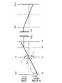
これについて図3を参照して具体的に説明する。図3は、クラッチ同期制御時のハイブリッド駆動装置10の一動作状態を例示する動作共線図である。図3において、縦軸は回転数を表しており、横軸は、左から順に、サンギヤS1(一義的に、モータMG1)、キャリアC1(一義的に、エンジン20)、係合要素RCL(一義的に、リングギヤR1)、ピニオンギヤP1、係合要素OCL(一義的に、駆動軸OUT)及びモータMG2を表す。また、図3の矢印「Y1」は、モータMG1による力行トルクに相当し、矢印「Y2」は、エンジン回転トルクTcに相当し、矢印「Y3」は、摩擦トルクTefに相当する。また、動作点「Pe1」は、エンジン回転数Neが「0」の場合のエンジン20の動作点を示す。
This will be specifically described with reference to FIG. FIG. 3 is an operation alignment chart illustrating one operation state of the
図3に示すように、ECU100は、摩擦トルクTefを利用して、エンジン20の動作点Pe1を支点として、MG1トルクTmg1を矢印Y1の方向に加え、係合要素RCLの回転数を係合要素OCLの回転数と同期させる。これに伴い、MG1トルクTmg1やクラッチCLでの摩擦トルクがエンジン20に対して負荷となり、矢印Y2に示すエンジン回転トルクTcが発生する。そして、矢印Y2に示すエンジン回転トルクTcが矢印Y3に示す摩擦トルクTefよりも大きくなった場合、エンジン20の動作点は、動作点Pe1から負回転方向に遷移し、エンジン20が逆回転することになる。
As shown in FIG. 3,
以上を勘案し、ECU100は、MG1トルクTmg1が負回転方向に作用し、かつ、エンジン回転トルクTcが摩擦トルクTefより大きくなると判断した場合には、モータMG1に印加する電流値(「MG1印加電流値Img1」とも呼ぶ。)を再設定してMG1トルクTmg1を変更する。言い換えると、MG1トルクTmg1が負回転方向に作用する場合、MG1トルクTmg1がエンジン20に伝達される比率を「Pro」とすると、ECU100は、以下の式(3)を満たすと判断した場合には、MG1印加電流値Img1を再設定する。
Tmg1×Pro>Tef (3)
ここで、比率Proは、ギヤ比によって一意に定まる値であり、具体的には、式(1)に基づき、以下の式(4)の関係を満たす。
Pro=(1+P)/P (4)
従って、ECU100は、例えば、MG1トルクTmg1に比率Proを乗じた値「Tmg1×Pro」が摩擦トルクTef以上になったと判断した場合、即ち、
Tmg1×Pro≧Tef (5)
が満たされたと判断した場合、式(3)が満たされる可能性があると判断する。そして、この場合、ECU100は、負回転方向に作用するMG1トルクTmg1を小さくするように、MG1印加電流値Img1を再設定する。なお、この場合、ECU100は、摩擦トルクTef及び比率Proを、予めメモリに記憶された値に設定する。また、ECU100は、MG1トルクTmg1を、MG1印加電流値Img1に基づき推定する。
In consideration of the above, when the
Tmg1 × Pro> Tef (3)
Here, the ratio Pro is a value uniquely determined by the gear ratio, and specifically satisfies the relationship of the following expression (4) based on the expression (1).
Pro = (1 + P) / P (4)
Therefore, for example, when the
Tmg1 × Pro ≧ Tef (5)
When it is determined that is satisfied, it is determined that the expression (3) may be satisfied. In this case,
このようにすることで、ECU100は、クラッチ同期制御中にMG1トルクTmg1がエンジン20に対して逆回転方向のトルクとして伝達されることに起因したエンジン20の逆回転を抑制することができる。また、ECU100は、クラッチ同期制御中に、エンジン20が逆回転しない範囲で出力可能なMG1トルクTmg1の上限値を式(3)又は式(5)に基づき把握することが可能である。従って、ECU100は、クラッチ同期制御中に、エンジン20が逆回転する虞がない範囲でMG1トルクTmg1を最大限大きくでき、クラッチCLを同期させる時間を短縮し、EV走行からシリーズパラレル式走行への移行時間を短縮化することが可能となる。
By doing in this way, ECU100 can suppress reverse rotation of
(処理フロー)
図4は、第1実施形態においてECU100が実行する処理手順を示すフローチャートの一例である。ECU100は、図4に示すフローチャートの処理を、所定の周期に従い繰り返し実行する。
(Processing flow)
FIG. 4 is an example of a flowchart showing a processing procedure executed by the
まず、ECU100は、EV走行中であるか否か判定する(ステップS101)。そして、ECU100は、EV走行中であると判断した場合(ステップS101;Yes)、クラッチCLの係合の要否を判断するためのフラグ(「クラッチ係合フラグ」とも呼ぶ。)がオンになっているか否か判定する(ステップS102)。なお、ここでは、クラッチ係合フラグは、クラッチCLが解放状態にあるEV走行から、クラッチCLを係合状態に移行させてシリーズパラレル式走行へ切り替えるべき走行状態にある場合に、オンに設定される。そして、ECU100は、クラッチ係合フラグがオンの場合(ステップS102;Yes)、ステップS103へ処理を進める。
First, the
一方、ECU100は、EV走行中ではない場合(ステップS101;No)、又は、クラッチ係合フラグがOFFの場合(ステップS102;No)、フローチャートの処理を終了する。
On the other hand, if the
次に、ECU100は、ステップS103で、クラッチ同期制御を開始する(ステップS103)。具体的には、ECU100は、MG1印加電流値Img1を定め、MG1トルクTmg1を調整することで、係合要素RCLの回転数を係合要素OCLの回転数に合わせる。そして、ECU100は、エンジン回転数Neが「0」であるか否か判定する(ステップS104)。そして、ECU100は、エンジン回転数Neが「0」であると判断した場合(ステップS104;Yes)、MG1トルクTmg1が負値であるか否か判定する(ステップS105)。そして、ECU100は、MG1トルクTmg1が負値であると判断した場合(ステップS105;Yes)、即ち、MG1トルクTmg1が負回転方向に作用すると判断した場合、ステップS106へ処理を進める。一方、ECU100は、エンジン回転数Neが「0」ではない場合(ステップS104;No)、又は、MG1トルクTmg1が負値ではない場合(ステップS105;No)、ステップS107へ処理を進める。
Next, the
そして、ECU100は、ステップS106で、エンジン回転トルクTcが摩擦トルクTefより小さいか否か判定する(ステップS106)。具体的には、ECU100は、MG1トルクTmg1に比率Proを乗じた値「Tmg1×Pro」が摩擦トルクTefより小さくなるか否か判定する。この場合、ECU100は、例えば、MG1トルクTmg1を、MG1印加電流値Img1の現在の設定値に基づき推定する。そして、ECU100は、エンジン回転トルクTcが摩擦トルクTefより小さいと判断した場合(ステップS106;Yes)、MG1トルクTmg1を調整する必要はないと判断し、ステップS107へ処理を進める。
In step S106, the
一方、ECU100は、エンジン回転トルクTcが摩擦トルクTef以上であると判断した場合(ステップS106;No)、即ち式(5)が満たされたと判断した場合、MG1印加電流値Img1を再設定する(ステップS108)。具体的には、ECU100は、負回転方向に作用するMG1トルクTmg1を弱めるように、即ちMG1トルクTmg1の絶対値を小さくするように、MG1印加電流値Img1を再設定する。これにより、ECU100は、エンジン20が逆回転するのを抑制することができる。
On the other hand, when
次に、ECU100は、ステップS107で、クラッチCLの同期が完了したか否か判定する(ステップS107)。例えば、ECU100は、係合要素RCLと係合要素OCLとの回転数差が所定値以内になった場合、クラッチ同期制御が完了したと判断する。そして、ECU100は、クラッチCLの同期が完了したと判断した場合(ステップS107;Yes)、クラッチCLを係合状態に移行させ、エンジン20を始動させる(ステップS109)。具体的には、ECU100は、上述したクラッチ係合制御及びエンジン始動制御を実行する。これにより、ECU100は、EV走行からシリーズパラレル式走行へ切り替える。一方、ECU100は、クラッチCLの同期が完了していないと判断した場合(ステップS107;No)、ステップS104へ処理を戻す。
Next, the
<第2実施形態>
第2実施形態では、第1実施形態に加え、ECU100は、エンジン回転数Neが負値になった場合、エンジン回転数Neが「0」以上になるようにMG1印加電流値Img1を再設定する。これにより、ECU100は、エンジン回転数Neが所定回転数以上逆回転するのを確実に防止する。
Second Embodiment
In the second embodiment, in addition to the first embodiment, the
これについて補足説明する。上述したように、ECU100が摩擦トルクTefとして使用する値は、事前にECU100のメモリに記憶された推定値であり、号機差、経年変化などによって実値と誤差(推定誤差)が生じる。さらに、ECU100は、式(5)に基づきMG1印加電流値Img1を再設定すべきか否か判断する場合に、現在のMG1印加電流値Img1から所定のマップ又は式を参照して、MG1トルクTmg1を推定する。しかし、これによって得られたMG1トルクTmg1も推定値であり、正確な推定が難しい場合が多い。
This will be supplementarily described. As described above, the value that the
以上を勘案し、第2実施形態では、ECU100は、式(5)に基づく判定に加えて、センサなどで監視できる変数に基づきエンジン20が逆回転するか否か判定する。具体的には、ECU100は、回転数センサ15により検出したエンジン回転数Neが負回転数になった場合、エンジン回転数Neが「0」以上になるようにMG1印加電流値Img1を再設定する。これにより、ECU100は、エンジン回転数Neが逆回転するのを抑制すると共に、エンジン20が逆回転した場合であっても、エンジン20を直ちに正回転又は0回転に戻し、許容される所定回転数以上逆回転するのを防ぐことができる。
Considering the above, in the second embodiment, the
(処理フロー)
図5は、第2実施形態においてECU100が実行する処理手順を示すフローチャートの一例である。ECU100は、図5に示すフローチャートの処理を、所定の周期に従い繰り返し実行する。
(Processing flow)
FIG. 5 is an example of a flowchart illustrating a processing procedure executed by the
まず、ECU100は、EV走行中であるか否か判定する(ステップS201)。そして、ECU100は、EV走行中であると判断した場合(ステップS201;Yes)、クラッチ係合フラグがオンになっているか否か判定する(ステップS202)。そして、ECU100は、クラッチ係合フラグがオンの場合(ステップS202;Yes)、ステップS203へ処理を進める。一方、ECU100は、EV走行中ではない場合(ステップS201;No)、又は、クラッチ係合フラグがオフの場合(ステップS202;No)、フローチャートの処理を終了する。
First, the
次に、ECU100は、ステップS203で、クラッチ同期制御を開始する(ステップS203)。そして、ECU100は、エンジン回転数Neが「0」であると判断し(ステップS204;Yes)、かつ、MG1トルクTmg1が負値であると判断した場合(ステップS205;Yes)、ステップS206へ処理を進める。一方、ECU100は、エンジン回転数Neが「0」ではない場合(ステップS204;No)、又は、MG1トルクTmg1が負値ではない場合(ステップS204;No)、ステップS207へ処理を進める。
Next, the
そして、ECU100は、ステップS206で、エンジン回転トルクTcが摩擦トルクTefより小さいか否か判定する(ステップS206)。そして、ECU100は、エンジン回転トルクTcが摩擦トルクTefより小さいと判断した場合(ステップS206;Yes)、エンジン回転数Neが「0」以上であるか否か判定する(ステップS207)。これにより、ECU100は、推定値でなく回転数センサ15による検出値に基づき、エンジン20が逆回転しているか確実に判定することができ、エンジン20が所定回転数以上逆回転するのを抑制する。そして、ECU100は、エンジン回転数Neが「0」以上であると判断した場合(ステップS207;Yes)、ステップS208へ処理を進める。
In step S206, the
一方、ECU100は、エンジン回転トルクTcが摩擦トルクTef以上であると判断した場合(ステップS206;No)、MG1印加電流値Img1を再設定する(ステップS209)。これにより、ECU100は、エンジン20が逆回転するのを抑制することができる。
On the other hand, when the
同様に、ECU100は、ステップS207で、エンジン回転数Neが「0」未満であると判断した場合(ステップS207;No)、MG1印加電流値Img1を再設定する(ステップS209)。具体的には、ECU100は、エンジン回転数Neが「0」以上になるように、MG1印加電流値Img1を再設定する。これにより、ECU100は、エンジン20を直ちに正回転又は0回転に戻し、許容される所定回転数以上逆回転するのを防ぐことができる。
Similarly, when the
次に、ECU100は、ステップS208で、クラッチCLの同期が完了したか否か判定する(ステップS208)。そして、ECU100は、クラッチCLの同期が完了したと判断した場合(ステップS208;Yes)、クラッチCLを係合状態に移行させ、エンジン20を始動させる(ステップS210)。これにより、ECU100は、EV走行からシリーズパラレル式走行へ走行モードを切り替える。一方、ECU100は、クラッチCLの同期が完了していないと判断した場合(ステップS208;No)、ステップS204へ処理を戻す。
Next,
1 ハイブリッド車両
10 ハイブリッド駆動装置
12 バッテリ
20 エンジン
30 動力分割機構
40 入力軸
60 減速機構
100 ECU
MG1、MG2 モータジェネレータ
CL クラッチ
DESCRIPTION OF
MG1, MG2 Motor generator CL Clutch
Claims (2)
第1回転電機と、
第2回転電機と、
前記第1回転電機に連結された第1回転要素と、前記第2回転電機と駆動軸とにクラッチを介して連結する第2回転要素と、前記エンジンと連結する第3回転要素と、を含む相互に差動回転可能な複数の回転要素を備えた動力伝達機構と、
前記クラッチを解放状態にし、前記エンジンを停止させて前記第2回転電機により走行を行う第1走行モードから、前記クラッチを係合状態にし、前記エンジンを駆動させて走行を行う第2走行モードへ走行モードを切り替える場合、前記エンジンの始動前に前記第1回転電機のトルクに基づき前記クラッチの係合要素の回転を同期させる制御を行うクラッチ同期制御手段と、
前記クラッチ同期制御手段が、前記制御を実行している場合、前記エンジンに伝達される前記第1回転電機のトルクが、前記エンジンの摩擦トルク以下になるように制限するトルク制限手段と、
を備えることを特徴とするハイブリッド車両の制御装置。 Engine,
A first rotating electrical machine;
A second rotating electrical machine;
A first rotating element connected to the first rotating electric machine, a second rotating element connected to the second rotating electric machine and a drive shaft via a clutch, and a third rotating element connected to the engine. A power transmission mechanism having a plurality of rotating elements capable of differential rotation with each other;
From the first traveling mode in which the clutch is disengaged and the engine is stopped and traveling by the second rotating electrical machine is changed to the second traveling mode in which the clutch is engaged and the engine is driven to travel. Clutch switching control means for performing control to synchronize the rotation of the engagement element of the clutch based on the torque of the first rotating electrical machine before starting the engine when switching the running mode;
Torque limiting means for limiting the torque of the first rotating electrical machine transmitted to the engine to be equal to or less than the friction torque of the engine when the clutch synchronization control means is executing the control;
A control apparatus for a hybrid vehicle, comprising:
前記クラッチ同期制御手段が、前記制御を実行している際、前記エンジン回転数検出手段により前記回転数が負値であることを検出した場合、前記回転数が負値にならないように前記第1回転電機を制御する第1回転電機制御手段と、
をさらに備える請求項1に記載のハイブリッド車両の制御装置。 Engine speed detecting means for detecting the engine speed;
When the clutch synchronization control means detects that the engine speed is a negative value by the engine speed detector while the control is being performed, the first speed is set so that the engine speed does not become a negative value. First rotating electrical machine control means for controlling the rotating electrical machine;
The control device for a hybrid vehicle according to claim 1, further comprising:
Priority Applications (1)
| Application Number | Priority Date | Filing Date | Title |
|---|---|---|---|
| JP2011004663A JP5691534B2 (en) | 2011-01-13 | 2011-01-13 | Control device for hybrid vehicle |
Applications Claiming Priority (1)
| Application Number | Priority Date | Filing Date | Title |
|---|---|---|---|
| JP2011004663A JP5691534B2 (en) | 2011-01-13 | 2011-01-13 | Control device for hybrid vehicle |
Publications (2)
| Publication Number | Publication Date |
|---|---|
| JP2012144171A true JP2012144171A (en) | 2012-08-02 |
| JP5691534B2 JP5691534B2 (en) | 2015-04-01 |
Family
ID=46788213
Family Applications (1)
| Application Number | Title | Priority Date | Filing Date |
|---|---|---|---|
| JP2011004663A Expired - Fee Related JP5691534B2 (en) | 2011-01-13 | 2011-01-13 | Control device for hybrid vehicle |
Country Status (1)
| Country | Link |
|---|---|
| JP (1) | JP5691534B2 (en) |
Cited By (1)
| Publication number | Priority date | Publication date | Assignee | Title |
|---|---|---|---|---|
| US20200114902A1 (en) * | 2018-10-11 | 2020-04-16 | Hyundai Motor Company | Apparatus and method for controlling driving of vehicle, and vehicle system |
Citations (6)
| Publication number | Priority date | Publication date | Assignee | Title |
|---|---|---|---|---|
| JPH08295140A (en) * | 1995-04-28 | 1996-11-12 | Aqueous Res:Kk | Hybrid vehicle |
| JP2002012046A (en) * | 2000-06-28 | 2002-01-15 | Aisin Aw Co Ltd | Hybrid vehicle |
| JP2004249943A (en) * | 2003-02-21 | 2004-09-09 | Toyota Motor Corp | Vehicle drive system |
| JP2005337491A (en) * | 2004-04-27 | 2005-12-08 | Toyota Motor Corp | Control device for vehicle drive device |
| JP2008168810A (en) * | 2007-01-12 | 2008-07-24 | Toyota Motor Corp | Powertrain control device, control method, program for realizing the method, and recording medium recording the program |
| JP2009143526A (en) * | 2007-12-13 | 2009-07-02 | Hyundai Motor Co Ltd | Method for limiting motor torque of hybrid vehicle |
-
2011
- 2011-01-13 JP JP2011004663A patent/JP5691534B2/en not_active Expired - Fee Related
Patent Citations (6)
| Publication number | Priority date | Publication date | Assignee | Title |
|---|---|---|---|---|
| JPH08295140A (en) * | 1995-04-28 | 1996-11-12 | Aqueous Res:Kk | Hybrid vehicle |
| JP2002012046A (en) * | 2000-06-28 | 2002-01-15 | Aisin Aw Co Ltd | Hybrid vehicle |
| JP2004249943A (en) * | 2003-02-21 | 2004-09-09 | Toyota Motor Corp | Vehicle drive system |
| JP2005337491A (en) * | 2004-04-27 | 2005-12-08 | Toyota Motor Corp | Control device for vehicle drive device |
| JP2008168810A (en) * | 2007-01-12 | 2008-07-24 | Toyota Motor Corp | Powertrain control device, control method, program for realizing the method, and recording medium recording the program |
| JP2009143526A (en) * | 2007-12-13 | 2009-07-02 | Hyundai Motor Co Ltd | Method for limiting motor torque of hybrid vehicle |
Cited By (2)
| Publication number | Priority date | Publication date | Assignee | Title |
|---|---|---|---|---|
| US20200114902A1 (en) * | 2018-10-11 | 2020-04-16 | Hyundai Motor Company | Apparatus and method for controlling driving of vehicle, and vehicle system |
| US10967850B2 (en) * | 2018-10-11 | 2021-04-06 | Hyundai Motor Company | Apparatus and method for controlling driving of vehicle, and vehicle system |
Also Published As
| Publication number | Publication date |
|---|---|
| JP5691534B2 (en) | 2015-04-01 |
Similar Documents
| Publication | Publication Date | Title |
|---|---|---|
| US10179507B2 (en) | Right and left motor output control for vehicle | |
| JP4631936B2 (en) | POWER OUTPUT DEVICE, ITS CONTROL METHOD, AND VEHICLE | |
| JP2011063089A (en) | Device for control of hybrid electric vehicle | |
| US9242642B2 (en) | Electrically-powered vehicle and method of controlling the same | |
| JP2011156997A (en) | Controller for hybrid vehicle | |
| JP2017043299A (en) | Hybrid vehicle | |
| JP2009184500A (en) | Vehicle and control method thereof | |
| JP2012144172A (en) | Controller for hybrid vehicle | |
| JP2013180696A (en) | Control device for hybrid electric vehicle | |
| CN108082178A (en) | Hybrid vehicle | |
| JP2012030761A (en) | Control apparatus of hybrid vehicle | |
| JP5803892B2 (en) | Control device for hybrid vehicle | |
| JP5648461B2 (en) | Control device for hybrid vehicle | |
| JP5728846B2 (en) | Control device for hybrid vehicle | |
| JP5691534B2 (en) | Control device for hybrid vehicle | |
| JP6447154B2 (en) | Vehicle drive device | |
| JP5761327B2 (en) | Control device for hybrid vehicle | |
| JP6096594B2 (en) | Vehicle control apparatus, vehicle including the same, and vehicle control method | |
| JP5703738B2 (en) | Control device for hybrid vehicle | |
| JP2021011137A (en) | Hybrid vehicle | |
| JP2012071693A (en) | Hybrid vehicle drive control device | |
| JP5824501B2 (en) | Control device for hybrid vehicle | |
| JP2008148528A (en) | Vehicle and control method thereof | |
| JP5299294B2 (en) | Vehicle control device | |
| WO2017013843A1 (en) | Vehicular power source device and method of controlling vehicular power source device |
Legal Events
| Date | Code | Title | Description |
|---|---|---|---|
| A621 | Written request for application examination |
Free format text: JAPANESE INTERMEDIATE CODE: A621 Effective date: 20131016 |
|
| A977 | Report on retrieval |
Free format text: JAPANESE INTERMEDIATE CODE: A971007 Effective date: 20140522 |
|
| A131 | Notification of reasons for refusal |
Free format text: JAPANESE INTERMEDIATE CODE: A131 Effective date: 20140527 |
|
| A02 | Decision of refusal |
Free format text: JAPANESE INTERMEDIATE CODE: A02 Effective date: 20141014 |
|
| A521 | Request for written amendment filed |
Free format text: JAPANESE INTERMEDIATE CODE: A523 Effective date: 20141117 |
|
| A911 | Transfer to examiner for re-examination before appeal (zenchi) |
Free format text: JAPANESE INTERMEDIATE CODE: A911 Effective date: 20141215 |
|
| TRDD | Decision of grant or rejection written | ||
| A01 | Written decision to grant a patent or to grant a registration (utility model) |
Free format text: JAPANESE INTERMEDIATE CODE: A01 Effective date: 20150106 |
|
| A61 | First payment of annual fees (during grant procedure) |
Free format text: JAPANESE INTERMEDIATE CODE: A61 Effective date: 20150119 |
|
| R151 | Written notification of patent or utility model registration |
Ref document number: 5691534 Country of ref document: JP Free format text: JAPANESE INTERMEDIATE CODE: R151 |
|
| LAPS | Cancellation because of no payment of annual fees |