JP2012144166A - Assembling method of power train, and assembling auxiliary tool - Google Patents
Assembling method of power train, and assembling auxiliary tool Download PDFInfo
- Publication number
- JP2012144166A JP2012144166A JP2011004452A JP2011004452A JP2012144166A JP 2012144166 A JP2012144166 A JP 2012144166A JP 2011004452 A JP2011004452 A JP 2011004452A JP 2011004452 A JP2011004452 A JP 2011004452A JP 2012144166 A JP2012144166 A JP 2012144166A
- Authority
- JP
- Japan
- Prior art keywords
- power train
- vehicle
- guide rod
- bracket
- hole
- Prior art date
- Legal status (The legal status is an assumption and is not a legal conclusion. Google has not performed a legal analysis and makes no representation as to the accuracy of the status listed.)
- Pending
Links
Images
Landscapes
- Automobile Manufacture Line, Endless Track Vehicle, Trailer (AREA)
- Automatic Assembly (AREA)
Abstract
【課題】パワートレインを容易に車体へ組み付けできる、パワートレインの組み付け方法および組付補助具を提供すること。
【解決手段】サイドフレーム4,5間にパワートレイン6を配置し、サイドフレーム上部に防振ゴム9,12を介して取り付けた上側ブラケット10,13の下面部に上面が接合される下側ブラケット11,14をパワートレイン6に取り付け、パワートレイン6を車両1の下方から上方へ移動させて下側ブラケット11,14に固定したボルト15,16を車両1の下方から上側ブラケット10,13の貫通孔に挿入するパワートレイン6の組み付け方法において、ボルト15,16の先端部に車両上下方向へ延びるガイドロッド19,20を着脱可能に取り付け、ガイドロッド19,20によってボルト15,16と貫通孔の位置合わせを行う。
【選択図】図3To provide a powertrain assembly method and an assembly auxiliary tool capable of easily assembling a powertrain to a vehicle body.
A lower bracket in which a power train 6 is disposed between side frames 4 and 5 and an upper surface is joined to lower surfaces of upper brackets 10 and 13 attached to the upper side of the side frame via vibration-proof rubbers 9 and 12. 11 and 14 are attached to the power train 6, and the bolts 15 and 16, which are fixed to the lower brackets 11 and 14 by moving the power train 6 from the lower side to the upper side of the vehicle 1, penetrate the upper brackets 10 and 13 from the lower side of the vehicle 1. In the method of assembling the power train 6 to be inserted into the hole, guide rods 19 and 20 extending in the vehicle vertical direction are detachably attached to the tip portions of the bolts 15 and 16, and the bolts 15 and 16 and the through holes are connected by the guide rods 19 and 20. Perform alignment.
[Selection] Figure 3
Description
この発明はパワートレインの組み付け方法および組付補助具に係り、特にパワートレインを車体へ組み付けする際の組み付け方法の改善を図るとともに、組付補助具の提供をも行うパワートレインの組み付け方法および組付補助具に関するものである。 BACKGROUND OF THE INVENTION 1. Field of the Invention The present invention relates to a powertrain assembling method and an assembling auxiliary tool, and in particular, to improve the assembling method when assembling a powertrain to a vehicle body, and to provide an assembling auxiliary tool and an assembling method and an assembly of the powertrain. It relates to auxiliary equipment.
従来、パワートレインを車体に支持するブラケットは車体に固定される上側ブラケットと前記パワートレインに連結される下側ブラケットとに分割されていた。
そして、この下側ブラケットにボルトを固定する一方、前記上側ブラケットに貫通孔を形成し、パワートレインを車両下方から上方へ移動させることによって、ボルトを貫通孔に挿入し、その後ナットにより両者を締結していた。
Conventionally, the bracket for supporting the power train on the vehicle body is divided into an upper bracket fixed to the vehicle body and a lower bracket connected to the power train.
Then, while fixing the bolt to the lower bracket, a through hole is formed in the upper bracket, and the power train is moved upward from the lower side of the vehicle to insert the bolt into the through hole, and then fasten both with a nut. Was.
ところで、従来のパワートレインの組み付け方法および組付補助具においては、ボルトと貫通孔の位置合わせを容易にするため、上記の特許文献1に開示されるように、ボルトの先端に位置含わせ用のガイド部を設けたものがあった。
しかし、従来のガイド部はボルトと一体的に形成されているため、長さをあまり長くすることができなかった。
このため、ガイド部が貫通孔と接近する位置までパワートレインを上方へ移動させると、ガイド部および貫通孔が下側ブラケットの影に隠れて両者の位置合わせが困難になるという不都合がある。
また、車両前後方向に延びる左右のサイドフレームの上側に防振ゴムを介して上側ブラケットを取り付け、下側ブラケットをパワートレインの車両幅方向両側部に取り付けた場合には、前記パワートレインを車体に組み付ける際にこのパワートレインを左右のサイドフレームに挟まれた空間で上方へ移動させる必要がある。
しかし、従来は、前記下側ブラケットが左右のサイドメンバより下側にある場合、パワートレインと左右のサイドフレームの相対的な位置が規制できないため、前記パワートレインを上方へ移動させる途中で前記下側ブラケットが左右のサイドフレームと接触する可能性があるという不都合がある。
By the way, in the conventional powertrain assembling method and the assembling auxiliary tool, in order to facilitate the alignment of the bolt and the through hole, as disclosed in the above-mentioned Patent Document 1, it is used for positioning at the tip of the bolt. There was one provided with a guide part.
However, since the conventional guide part is formed integrally with the bolt, the length cannot be made too long.
For this reason, when the power train is moved upward to a position where the guide portion approaches the through hole, there is an inconvenience that the guide portion and the through hole are hidden by the shadow of the lower bracket, making it difficult to align them.
In addition, when the upper bracket is attached to the upper side of the left and right side frames extending in the vehicle front-rear direction via anti-vibration rubber and the lower bracket is attached to both sides in the vehicle width direction of the power train, the power train is attached to the vehicle body. When assembling, it is necessary to move the power train upward in a space between the left and right side frames.
However, conventionally, when the lower bracket is located below the left and right side members, the relative positions of the power train and the left and right side frames cannot be regulated. There is a disadvantage that the side bracket may come into contact with the left and right side frames.
この発明は、パワートレインを容易に車体へ組み付けできるパワートレインの組み付け方法および組付補助具を提供することを目的とする。 An object of the present invention is to provide a powertrain assembling method and an assembling auxiliary tool capable of easily assembling a powertrain to a vehicle body.
そこで、この発明は、上述不都合を除去するために、車両前後方向に延びるサイドフレーム間にパワートレインを配置し、前記サイドフレームの上部に防振ゴムを介して上側ブラケットを取り付け、前記上側ブラケットの下面部にその上面が接合される下側ブラケットを前記パワートレインの車両幅方向端部に取り付け、前記パワートレインを車両下方から上方へ移動させることによって前記下側ブラケットに固定したボルトを車両下方から前記上側ブラケットの貫通孔に挿入するパワートレインの組み付け方法において、前記ボルトの先端部に車両上下方向へ延びるガイドロッドを着脱可能に取り付け、前記ガイドロッドによって前記ボルトと前記貫通孔の位置合わせを行うことを特徴とする。
また、車両前後方向に延びるサイドフレーム間にパワートレインを配置し、前記サイドフレームの上部に防振ゴムを介して上側ブラケットを取り付け、前記上側ブラケットの下面部にその上面が接合される下側ブラケットを前記パワートレインの車両幅方向端部に取り付け、前記パワートレインを車両下方から上方へ移動させることによって前記下側ブラケットに固定したボルトを車両下方から前記上側ブラケットの貫通孔に挿入する際に使用するパワートレインの組み付け補助具において、前記ボルトの先端部にガイドロッド取付部を形成し、このガイドロッド取付部に車両上方へ延びるガイドロッドを着脱可能に取り付けたことを特徴とする。
Therefore, in order to eliminate the above-described inconveniences, the present invention arranges a power train between side frames extending in the vehicle front-rear direction, attaches an upper bracket to the upper portion of the side frame via an anti-vibration rubber, and A lower bracket whose upper surface is joined to the lower surface is attached to an end of the power train in the vehicle width direction, and the bolt fixed to the lower bracket is moved from the lower side of the vehicle by moving the power train from the lower side to the upper side of the vehicle. In the method of assembling the power train to be inserted into the through hole of the upper bracket, a guide rod extending in the vehicle vertical direction is detachably attached to the tip of the bolt, and the bolt and the through hole are aligned by the guide rod. It is characterized by that.
A lower bracket in which a power train is disposed between side frames extending in the vehicle front-rear direction, an upper bracket is attached to the upper portion of the side frame via an anti-vibration rubber, and an upper surface thereof is joined to a lower surface portion of the upper bracket. Is attached to the end of the power train in the vehicle width direction, and is used when a bolt fixed to the lower bracket by moving the power train from the lower side of the vehicle to the upper side is inserted into the through hole of the upper bracket from the lower side of the vehicle. In the powertrain assembly assisting tool, a guide rod attachment portion is formed at the tip of the bolt, and a guide rod extending upward of the vehicle is detachably attached to the guide rod attachment portion.
以上詳細に説明した如くこの発明によれば、車両前後方向に延びるサイドフレーム間にパワートレインを配置し、サイドフレームの上部に防振ゴムを介して上側ブラケットを取り付け、上側ブラケットの下面部にその上面が接合される下側ブラケットをパワートレインの車両幅方向端部に取り付け、パワートレインを車両下方から上方へ移動させることによって下側ブラケットに固定したボルトを車両下方から上側ブラケットの貫通孔に挿入するパワートレインの組み付け方法において、ボルトの先端部に車両上下方向へ延びるガイドロッドを着脱可能に取り付け、ガイドロッドによってボルトと貫通孔の位置合わせを行う。
従って、上記パワートレインの組み付け方法によれば、ガイドロッドの長さをかなり長くできる。このため、パワートレインが上側ブラケットから下方に離れた位置にあって、上側ブラケットの貫通孔を下方から目視できる状態で下側ブラケットに固定したボルトを貫通孔に位置合わせでき、パワートレインの車両に対する組み付け作業を容易にすることができる。
また、ガイドロッドはボルトに対して着脱可能であるため、従来のガイド部を備えたボルトと比べてボルト自体の全長を短縮でき、ボルトの軽量化が図れる。下側ブラケットと上側ブラケットの締結には車両1台当たり6本程度のボルトを使用するため、車両重量を大幅に軽量化して燃料消費を低減できる。
また、車両前後方向に延びるサイドフレーム間にパワートレインを配置し、サイドフレームの上部に防振ゴムを介して上側ブラケットを取り付け、上側ブラケットの下面部にその上面が接合される下側ブラケットをパワートレインの車両幅方向端部に取り付け、パワートレインを車両下方から上方へ移動させることによって下側ブラケットに固定したボルトを車両下方から上側ブラケットの貫通孔に挿入する際に使用するパワートレインの組み付け補助具において、ボルトの先端部にガイドロッド取付部を形成し、ガイドロッド取付部に車両上方へ延びるガイドロッドを着脱可能に取り付けた。
従って、パワートレイン組付用の補助具を、ボルトの先端部に形成されるガイドロッド取付部と、ガイドロッド取付部に着脱可能に装着されるガイドロッドとによって構成したため、パワートレインが上側ブラケットから下方に離れた位置にあり、上側ブラケットの貫通孔を下方から目視できる状態で下側ブラケットのボルトを上側ブラケットの貫通孔に位置合わせできるため、パワートレインの車両に対する組付作業を容易にできる。
As described above in detail, according to the present invention, the power train is disposed between the side frames extending in the vehicle front-rear direction, the upper bracket is attached to the upper portion of the side frame via the anti-vibration rubber, and the lower bracket portion is attached to the lower surface portion of the upper bracket. The lower bracket to which the upper surface is joined is attached to the vehicle width direction end of the power train, and the bolt fixed to the lower bracket by moving the power train from the lower side of the vehicle to the upper side is inserted into the through hole of the upper bracket from the lower side of the vehicle In the powertrain assembly method, a guide rod extending in the vertical direction of the vehicle is detachably attached to the tip of the bolt, and the bolt and the through hole are aligned by the guide rod.
Therefore, according to the method for assembling the power train, the length of the guide rod can be considerably increased. For this reason, the power train is located at a position away from the upper bracket downward, and the bolt fixed to the lower bracket can be aligned with the through hole in a state where the through hole of the upper bracket can be seen from below. Assembly work can be facilitated.
Moreover, since the guide rod can be attached to and detached from the bolt, the overall length of the bolt itself can be shortened compared to a bolt having a conventional guide portion, and the weight of the bolt can be reduced. Since about six bolts are used per vehicle for fastening the lower bracket and the upper bracket, the vehicle weight can be significantly reduced and fuel consumption can be reduced.
In addition, a power train is arranged between the side frames extending in the longitudinal direction of the vehicle, an upper bracket is attached to the upper part of the side frame via an anti-vibration rubber, and the lower bracket whose upper surface is joined to the lower surface of the upper bracket is powered. Assembling assistance for the power train used when inserting the bolt fixed to the lower bracket by moving the power train from the lower side of the vehicle to the upper side and inserting it into the through hole of the upper bracket from the lower side of the vehicle In the tool, a guide rod attachment portion is formed at the tip of the bolt, and a guide rod extending upward from the vehicle is detachably attached to the guide rod attachment portion.
Therefore, since the auxiliary tool for powertrain assembly is constituted by the guide rod mounting portion formed at the tip of the bolt and the guide rod that is detachably mounted on the guide rod mounting portion, the powertrain is separated from the upper bracket. Since the bolts of the lower bracket can be aligned with the through holes of the upper bracket while the through holes of the upper bracket can be viewed from below, the assembly work of the powertrain to the vehicle can be facilitated.
以下図面に基づいてこの発明の実施例を詳細に説明する。 Embodiments of the present invention will be described below in detail with reference to the drawings.
図1〜図8はこの発明の実施例を示すものである。
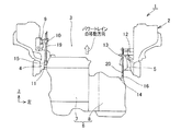
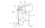
図3及び図4において、1は車両、2は車両1の車体、3はエンジンルームである。
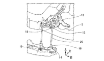
前記車両1は、図3及び図4に示す如く、車両前後方向に延びる前記車体2の一部を構成する右側の第1サイドフレーム4及び左側の第2サイドフレーム5間にパワートレイン6を配置する。
このとき、このパワートレイン6は、前記第1サイドフレーム4側に位置するエンジン7と、前記第2サイドフレーム5側に位置する変速機8とにより構成される。
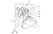
また、前記第1サイドフレーム4の上部に、右側の第1防振ゴム9を介して右側の第1上側ブラケット10を取り付けるとともに、この第1上側ブラケット10の下面部にその上面が接合される右側の第1下側ブラケット11を前記パワートレイン6の車両幅方向端部に取り付ける。
更に、前記第2サイドフレーム5の上部には、左側の第2防振ゴム12を介して左側の第2上側ブラケット13を取り付けるとともに、この第2上側ブラケット13の下面部にその上面が接合される左側の第2下側ブラケット14を前記パワートレイン6の車両幅方向端部に取り付ける。
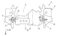
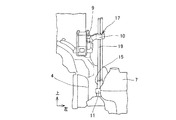
そして、前記パワートレイン6の組み付け方法は、このパワートレイン6を車両下方から上方へ移動させることによって前記第1、第2下側ブラケット11、14に夫々固定した右側及び左側の第1、第2ボルト15、16を車両下方から前記第1、第2上側ブラケット10、13の夫々の第1、第2貫通孔17、18に挿入して行う。
1 to 8 show an embodiment of the present invention.
3 and 4, 1 is a vehicle, 2 is a vehicle body of the
In the vehicle 1, as shown in FIGS. 3 and 4, a power train 6 is arranged between a
At this time, the power train 6 includes an
A first
Further, a left second
The power train 6 is assembled by moving the power train 6 from the lower side to the upper side of the vehicle, thereby fixing the first and second right and left sides fixed to the first and second
このとき、この発明の前記パワートレイン6の組み付け方法は、前記第1、第2ボルト15、16の先端部に車両上下方向へ延びる第1、第2ガイドロッド19、20を着脱可能に夫々取り付け、前記第1、第2ガイドロッド19、20によって前記第1、第2ボルト15、16と前記第1、第2貫通孔17、18の位置合わせを行う。
詳述すれば、前記第1、第2下側ブラケット11、14と前記第1、第2上側ブラケット10、13の締結に際しては、図1〜図6に示す如く、車両1台当たりで、前記第1ボルト15が3本と、前記第2ボルト16が3本との合計で6本のボルトを使用して行う。
従って、上記パワートレイン6の組み付け方法によれば、前記第1、第2ガイドロッド19、20の長さをかなり長くできる。このため、パワートレイン6が前記第1、第2上側ブラケット10、13から下方に離れた位置にあって、第1、第2上側ブラケット10、13の前記第1、第2貫通孔17、18を下方から目視できる状態で前記第1、第2下側ブラケット11、14に固定した前記第1、第2ボルト15、16を前記第1、第2貫通孔17、18に夫々位置合わせでき、パワートレイン6の前記車両1に対する組み付け作業を容易にすることができる。
また、前記第1、第2ガイドロッド19、20は前記第1、第2ボルト15、16に対して着脱可能であるため、従来のガイド部を備えたボルトと比べてボルト自体の全長を短縮でき、第1、第2ボルト15、16の軽量化が図れる。そして、前記第1、第2下側ブラケット11、14と前記第1、第2上側ブラケット10、13の締結には車両1台当たり6本程度のボルトを使用するため、車両重量を大幅に軽量化して燃料消費を低減できる。
At this time, according to the method of assembling the power train 6 of the present invention, the first and
More specifically, when the first and second
Therefore, according to the method for assembling the power train 6, the lengths of the first and
In addition, since the first and
また、前記パワートレイン6を車両下方から上方へ移動させることによって前記第1、第2下側ブラケット11、14に夫々固定した第1、第2ボルト15、16を車両下方から前記第1、第2上側ブラケット10、13の夫々の第1、第2貫通孔17、18に挿入する際に使用する前記パワートレイン6の組み付け補助具においては、前記第1、第2ボルト15、16の先端部に第1、第2ガイドロッド取付部21、22を形成し、この第1、第2ガイドロッド取付部21、22に車両上方へ延びる前記第1、第2ガイドロッド19、20を着脱可能に取り付ける構成とする。
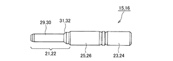
すなわち、前記第1、第2ボルト15、16において、図7に示す如く、一端側(図7において右側)から他端側(図7において左側)、つまり、前記第1、第2ボルト15、16の先端部に向かって、第1、第2植込み側ねじ部23、24と第1、第2締付用ねじ部25、26とを順次形成するとともに、この第1、第2締付用ねじ部25、26の他端側には、第1、第2植込み側ねじ部23、24及び第1、第2締付用ねじ部25、26よりも小径な前記第1、第2ガイドロッド取付部21、22を形成する。
そして、この第1、第2ガイドロッド取付部21、22に前記第1、第2ガイドロッド19、20を着脱可能に取り付けるものである。
従って、パワートレイン組付用の補助具を、前記第1、第2ボルト15、16の先端部に形成される前記第1、第2ガイドロッド取付部21、22と、第1、第2ガイドロッド取付部21、22に着脱可能に装着される前記第1、第2ガイドロッド19、20とによって構成したため、前記パワートレイン6が前記第1、第2上側ブラケット10、13から下方に離れた位置にあり、第1、第2上側ブラケット10、13の前記第1、第2貫通孔17、18を下方から目視できる状態で前記第1、第2下側ブラケット11、14の前記第1、第2ボルト15、16を第1、第2上側ブラケット10、13の第1、第2貫通孔17、18に位置合わせできるため、パワートレイン6の前記車両1に対する組付作業を容易にできる。
Further, the first and
That is, in the first and
The first and
Accordingly, the first and second guide rod mounting portions 21 and 22 formed at the tip ends of the first and
更に、前記パワートレイン6を車両1に組み付けする際に、前記第1、第2下側ブラケット11、14は前記第1、第2サイドフレーム4、5側方の空間をこの第1、第2サイドフレーム4、5の底面より下側から上方へ移動し、前記第1、第2下側ブラケット11、14が前記第1、第2サイドフレーム4、5の底面より下側にある状態で前記第1、第2ガイドロッド19、20の先端が前記第1、第2貫通孔17、18に達するように第1、第2ガイドロッド19、20の長さを設定する構成とする。
従って、前記第1、第2下側ブラケット11、14が前記第1、第2サイドフレーム4、5の側方の空間を通過する前に前記第1、第2ガイドロッド19、20によって前記第1、第2ボルト15、16と前記第1、第2貫通孔17、18を位置合わせでき、第1、第2下側ブラケット11、14が上方へ移動する際に第1、第2サイドフレーム4、5等と接触することが防止できる。
そのため、前記パワートレイン6の前記車両1に対する組付作業をさらに容易にできる。
Further, when the power train 6 is assembled to the vehicle 1, the first and second
Therefore, before the first and second
Therefore, the work of assembling the power train 6 to the vehicle 1 can be further facilitated.
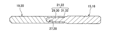
更にまた、前記第1、第2ガイドロッド19、20は下方に開口する第1、第2孔部27、28を夫々備え、前記第1、第2ガイドロッド取付部21、22は前記第1、第2孔部27、28の内側に挿入される第1、第2軸部29、30とこれらの第1、第2軸部29、30の下端部から径方向外側に広がる第1、第2テーパー部31、32とを夫々備えている。
つまり、前記第1、第2ガイドロッド19、20は、図8に示す如く、前記第1、第2孔部27、28を夫々形成している。
そして、前記第1、第2ガイドロッド取付部21、22には、図7及び図8に示す如く、前記第1、第2孔部27、28の内側に挿入される第1、第2軸部29、30と、第1、第2軸部29、30の下端部から径方向外側に広がる第1、第2テーパー部31、32とが夫々形成されている。
従って、前記第1、第2ガイドロッド取付部21、22を構成する前記第1、第2軸部29、30を前記第1、第2ガイドロッド19、20の前記第1、第2孔部27、28に挿入した場合、前記第1、第2孔部27、28の開口縁部が前記第1、第2テーパー部31、32と接触して第1、第2ガイドロッド19、20の軸心を前記第1、第2ボルト15、16の軸心と同軸に調整でき、前記パワートレイン6の前記車両1に対する組付作業をさらに容易にできる。
Furthermore, the first and
That is, the first and
As shown in FIGS. 7 and 8, the first and second shafts 21 and 22 are inserted into the first and second holes 27 and 28, as shown in FIGS. The portions 29 and 30 and the first and second tapered portions 31 and 32 that extend radially outward from the lower ends of the first and second shaft portions 29 and 30 are formed.
Accordingly, the first and second shaft portions 29 and 30 constituting the first and second guide rod mounting portions 21 and 22 are replaced with the first and second hole portions of the first and
なお、参考までに追記すれば、上述した前記パワートレイン6の組み付け方法及びパワートレイン6の組み付け補助具によって、以下の作用効果を奏することができるものである。
(a1)締結後に前記第1、第2ガイドロッド19、20を取り外すことができ、再利用可能である(最小限の投資で設備の大型化、ラインの改造が不要である。)。
(a2)前記第1、第2ガイドロッド19、20を挿入することで、倒れ防止を果たすことができる一方、この第1、第2ガイドロッド19、20の着脱が容易である(作業性を向上できる。)。
(a3)前記第1、第2ボルト15、16を短くすることができる(部品の小型化が可能となる。)。
(a4)前記第1、第2サイドフレーム4、5とのクリアランスの狭い箇所を、前記第1、第2下側ブラケット11、14を通過させる前に、前記第1、第2ガイドロッド19、20を前記第1、第2上側ブラケット10、13の第1、第2貫通孔17、18に通すことができるため、簡単で精度良く位置合わせを行うことができる(作業性を向上できる。)。
(a5)作業者一人でも位置合わせを行うことができる(人件費を削減することができる。)。
(a6)また、今までは、前記パワートレイン6の上昇後、位置が合わない場合に、パワートレイン6の位置を前後左右にズラシながら前記第1、第2ボルト15、16と前記第1、第2貫通孔17、18との位置合わせを行っていたので、周辺部品との干渉が発生していたが、この干渉も防止できる(作業性の向上、品質の向上が図れる。)。
In addition, if added for reference, the following operation and effect can be achieved by the above-described method of assembling the power train 6 and the assembly aid for the power train 6.
(A1) After the fastening, the first and
(A2) The insertion of the first and
(A3) The first and
(A4) Before passing the first and second
(A5) One worker can perform alignment (labor cost can be reduced).
(A6) Until now, after the power train 6 is lifted, if the position does not match, the first and
また、前記第1、第2ボルト15、16において、前記第1、第2ガイドロッド取付部21、22を第1、第2植込み側ねじ部23、24や第1、第2締付用ねじ部25、26よりも細くすることで、従来のガイド部を備えたボルトを使用するよりも前記第1、第2ガイドロッド19、20の外径を小さくすることができる。
そのため、前記第1、第2上側ブラケット10、13側の第1、第2貫通孔17、18の大きさを小さくできるため、以下の作用効果を奏することもできる。
(b1)よりねじ径の小さいナットでも必要座面を確保できる(ナットの小型化ができる。)。
(b2)前記第1、第2上側ブラケット10、13側の第1、第2貫通孔17、18を小径にできる(ブラケットの小型化ができる。)。
In the first and
Therefore, since the size of the first and second through
(B1) The required seating surface can be secured even with a nut having a smaller screw diameter (the nut can be reduced in size).
(B2) The first and second through
1 車両
2 車体
3 エンジンルーム
4 右側の第1サイドフレーム
5 左側の第2サイドフレーム
6 パワートレイン
7 エンジン
8 変速機
9 第1防振ゴム
10 第1上側ブラケット
11 第1下側ブラケット
12 第2防振ゴム
13 第2上側ブラケット
14 第2下側ブラケット
15、16 第1、第2ボルト
17、18 第1、第2貫通孔
19、20 第1、第2ガイドロッド
21、22 第1、第2ガイドロッド取付部
23、24 第1、第2植込み側ねじ部
25、26 第1、第2締付用ねじ部
27、28 第1、第2孔部
29、30 第1、第2軸部
31、32 第1、第2テーパー部
DESCRIPTION OF SYMBOLS 1
Claims (4)
Priority Applications (1)
| Application Number | Priority Date | Filing Date | Title |
|---|---|---|---|
| JP2011004452A JP2012144166A (en) | 2011-01-13 | 2011-01-13 | Assembling method of power train, and assembling auxiliary tool |
Applications Claiming Priority (1)
| Application Number | Priority Date | Filing Date | Title |
|---|---|---|---|
| JP2011004452A JP2012144166A (en) | 2011-01-13 | 2011-01-13 | Assembling method of power train, and assembling auxiliary tool |
Publications (1)
| Publication Number | Publication Date |
|---|---|
| JP2012144166A true JP2012144166A (en) | 2012-08-02 |
Family
ID=46788209
Family Applications (1)
| Application Number | Title | Priority Date | Filing Date |
|---|---|---|---|
| JP2011004452A Pending JP2012144166A (en) | 2011-01-13 | 2011-01-13 | Assembling method of power train, and assembling auxiliary tool |
Country Status (1)
| Country | Link |
|---|---|
| JP (1) | JP2012144166A (en) |
-
2011
- 2011-01-13 JP JP2011004452A patent/JP2012144166A/en active Pending
Similar Documents
| Publication | Publication Date | Title |
|---|---|---|
| CN102361769A (en) | Vehicle Vibration Source Installation Structure | |
| JP6455654B2 (en) | Vehicle power plant mounting structure | |
| JP4918912B2 (en) | Steering device | |
| JP2012144166A (en) | Assembling method of power train, and assembling auxiliary tool | |
| WO2015146783A1 (en) | Support structure of steering column | |
| KR20090083136A (en) | Apparatus for fixing sub-frame in automobile | |
| CN103538458A (en) | Power assembly suspended torsion bar and mounting structure thereof | |
| KR101526700B1 (en) | Subframe of vehicle installed stabilizer bar and steering device in one body | |
| KR101438336B1 (en) | Combination structure crossmember and body mounting bracket of subframe for automobile | |
| JP6635064B2 (en) | Temporary fixing structure of engine mount | |
| CN204222629U (en) | Engine support for construction machinery | |
| JP2018530466A (en) | Handling strut | |
| CN202986828U (en) | Straightly-operational shift mechanism for manual gearbox and manual gearbox assembly and car | |
| JP4424046B2 (en) | Brake booster mounting structure | |
| JP5358180B2 (en) | Headrest | |
| JP2010221905A (en) | Vibration source mounting structure | |
| JP2016060455A (en) | Pannier attachment structure of motor cycle | |
| JP5989500B2 (en) | Engine mount structure | |
| KR20120045165A (en) | Structure of subframe for vehicle | |
| JP6222438B2 (en) | Vehicle powertrain mounting device | |
| JP2015030380A (en) | Stabilizer mounting structure | |
| JP2007090997A (en) | Air cleaner duct mounting structure and air cleaner duct mounting method | |
| KR100944877B1 (en) | Gearbox mounting structure of the car | |
| KR20130005761A (en) | Structure of subframe for vehicle | |
| KR100737474B1 (en) | Mounter on car door impact pad |