JP2012144152A - Oil feeding part structure of fuel tank - Google Patents

Oil feeding part structure of fuel tank Download PDF

Info

Publication number
JP2012144152A
JP2012144152A JP2011004210A JP2011004210A JP2012144152A JP 2012144152 A JP2012144152 A JP 2012144152A JP 2011004210 A JP2011004210 A JP 2011004210A JP 2011004210 A JP2011004210 A JP 2011004210A JP 2012144152 A JP2012144152 A JP 2012144152A
Authority
JP
Japan
Prior art keywords
fuel
gun
fueling
wiping member
port
Prior art date
Legal status (The legal status is an assumption and is not a legal conclusion. Google has not performed a legal analysis and makes no representation as to the accuracy of the status listed.)
Granted
Application number
JP2011004210A
Other languages
Japanese (ja)
Other versions
JP5691532B2 (en
Inventor
Tetsushi Yamamoto
哲士 山本
Chiaki Kataoka
千明 片岡
Current Assignee (The listed assignees may be inaccurate. Google has not performed a legal analysis and makes no representation or warranty as to the accuracy of the list.)
Toyota Motor Corp
Original Assignee
Toyota Motor Corp
Priority date (The priority date is an assumption and is not a legal conclusion. Google has not performed a legal analysis and makes no representation as to the accuracy of the date listed.)
Filing date
Publication date
Application filed by Toyota Motor Corp filed Critical Toyota Motor Corp
Priority to JP2011004210A priority Critical patent/JP5691532B2/en
Publication of JP2012144152A publication Critical patent/JP2012144152A/en
Application granted granted Critical
Publication of JP5691532B2 publication Critical patent/JP5691532B2/en
Expired - Fee Related legal-status Critical Current
Anticipated expiration legal-status Critical

Links

Images

Landscapes

  • Details Of Rigid Or Semi-Rigid Containers (AREA)
  • Cooling, Air Intake And Gas Exhaust, And Fuel Tank Arrangements In Propulsion Units (AREA)

Abstract

【課題】給油ガンを給油口から抜くときに給油ガンの表面の燃料を拭い取ることが可能な燃料タンクの給油部構造を得る。
【解決手段】給油口26を構成する給油口部材16の内面には、給油口26に挿入された給油ガン28の外周面に下側から接触する拭い取り部材24が設けられている。給油ガン28を給油口26から引き抜くとき、給油ガン28の外周面に燃料が付着していても、この燃料の少なくとも一部が接触面34によって拭い取られる。
【選択図】図1
A fuel tank fueling part structure capable of wiping off fuel on a surface of a fueling gun when the fueling gun is removed from a fueling port.
A wiping member is provided on the inner surface of a fuel filler member constituting a fuel filler opening from the lower side to an outer peripheral surface of a fuel gun inserted into the fuel filler opening. When the fueling gun 28 is pulled out from the fueling port 26, even if fuel adheres to the outer peripheral surface of the fueling gun 28, at least a part of this fuel is wiped off by the contact surface 34.
[Selection] Figure 1

Description

本発明は、燃料タンクの給油部構造に関する。   The present invention relates to a fuel tank fueling portion structure.

自動車等の燃料タンクへの給油時、特に給油ガンを給油口から抜き取るときに、給油ガンの表面に付着した燃料が外部に漏出しないようにすることが好ましい。特許文献1には、給液ノズルのノズルパイプの筒先が給液口に挿入されている状態で、ノズルパイプ内に気体を噴射して内部に付着している残留油液を給液口内に排出することで、給液作業終了後にノズルパイプ先端から液垂れを起さないようにした給液装置が記載されている。   It is preferable that the fuel adhering to the surface of the fuel gun is not leaked to the outside when the fuel tank of an automobile or the like is supplied, especially when the fuel gun is removed from the fuel supply port. In Patent Document 1, in a state where the tube tip of the nozzle pipe of the liquid supply nozzle is inserted into the liquid supply port, gas is injected into the nozzle pipe and residual oil liquid adhering to the inside is discharged into the liquid supply port. Thus, there is described a liquid supply apparatus that prevents liquid dripping from the tip of the nozzle pipe after completion of the liquid supply operation.

しかし、特許文献1の構造では、ノズルパイプ内の油液を除去しているに過ぎず、その表面に付着した燃料を除去することはできない。   However, in the structure of Patent Document 1, only the oil liquid in the nozzle pipe is removed, and the fuel adhering to the surface cannot be removed.

特開2009−292478号公報JP 2009-292478 A

本発明は上記事実を考慮し、給油ガンを給油口から抜くときに給油ガンの表面の燃料を拭い取ることが可能な燃料タンクの給油部構造を得ることを課題とする。   In view of the above facts, the present invention has an object to obtain a fuel tank fueling part structure capable of wiping off the fuel on the surface of the fueling gun when the fueling gun is removed from the fueling port.

請求項1に記載の発明では、燃料タンクへの給油用の給油ガンが挿入される給油口を構成する給油口部材と、前記給油口部材の内部に設けられ、前記給油ガンが前記給油口から引き抜かれるときに給油ガンに接触して給油ガン表面の燃料を拭い取る拭い取り部材と、を有する。   In the first aspect of the present invention, a fuel filler member constituting a fuel filler port into which a fuel gun for fueling a fuel tank is inserted, and the fuel filler member are provided inside the fuel filler member, and the fuel gun is provided from the fuel filler port. And a wiping member that contacts the fuel gun and wipes off the fuel on the surface of the fuel gun when pulled out.

この燃料タンクの給油部構造では、給油ガンが給油口から引き抜かれるときは、給油口部材の内部に設けられた拭い取り部材が、給油ガンの表面に接触して給油ガン表面の燃料を拭い取って除去する。したがって、このような拭い取り部材が設けられていない構成と比較して、給油ガン表面に付着している燃料の量が少なくなる。給油ガンの表面に付着している燃料の、いわゆる液垂れを抑制できる。   In this fuel tank fueling part structure, when the fueling gun is pulled out from the fueling port, the wiping member provided inside the fueling port member comes into contact with the surface of the fueling gun and wipes the fuel on the surface of the fueling gun. To remove. Therefore, the amount of fuel adhering to the surface of the fuel gun is reduced as compared with a configuration in which such a wiping member is not provided. So-called dripping of the fuel adhering to the surface of the fuel gun can be suppressed.

請求項2に記載の発明では、請求項1に記載の発明において、前記給油口を開閉可能な開閉弁を備え、前記拭い取り部材が前記開閉弁よりも前記給油口の奥側に配置されている。   According to a second aspect of the present invention, in the first aspect of the present invention, an on-off valve capable of opening and closing the fuel filler opening is provided, and the wiping member is disposed on the deeper side of the fuel filler opening than the on-off valve. Yes.

したがって、開閉弁を開けて給油口を開放し、給油口部材の給油口に給油ガンを挿入することで燃料タンクへ給油することができる。拭い取り部材は開閉弁よりも給油口の奥側に配置されているので、給油ガンの表面に付着した燃料が開閉弁への転移(再付着)することを抑制できる。   Therefore, the fuel tank can be refueled by opening the on-off valve to open the refueling port and inserting the refueling gun into the refueling port of the refueling port member. Since the wiping member is disposed on the deeper side of the fuel filler opening than the on-off valve, it is possible to suppress the fuel adhering to the surface of the fuel gun from being transferred (reattached) to the on-off valve.

請求項3に記載の発明では、請求項1又は請求項2に記載の発明において、前記拭い取り部材に、前記給油ガンから拭い取った燃料が給油ガンに再付着しないように該燃料を給油ガン表面から離間した位置に逃がす逃がし部が形成されている。   According to a third aspect of the present invention, in the first or second aspect of the present invention, the fuel is supplied to the wiping member so that the fuel wiped off from the fuel supply gun does not reattach to the fuel supply gun. An escape portion is formed at a position spaced from the surface.

給油ガンから拭い取り部材により拭い取られた燃料が、逃がし部により、給油ガン表面から離間した位置に逃がされるので、効果的に給油ガン表面から燃料を除去することが可能になる。   Since the fuel wiped off from the fuel gun by the wiping member is released by the escape portion to a position separated from the surface of the fuel gun, the fuel can be effectively removed from the surface of the fuel gun.

請求項4に記載の発明では、請求項1〜請求項3のいずれか1項に記載の発明において、前記拭い取り部材が前記給油口部材に固定されている。   In invention of Claim 4, in the invention of any one of Claims 1-3, the said wiping member is being fixed to the said fuel filler member.

このように拭い取り部材を給油口部材に固定することで、簡単な構造で、給油ガンに対する給油口部材の接触状態を良好に維持できるようになる。   By fixing the wiping member to the fuel filler member in this way, the contact state of the fuel filler member with the fuel gun can be satisfactorily maintained with a simple structure.

請求項5に記載の発明では、請求項1〜請求項3のいずれか1項に記載の発明において、前記給油口部材に設けられ、前記拭い取り部材を前記給油口に挿入された給油ガンの外周面に押圧可能に支持する押圧支持部材、を有する。   According to a fifth aspect of the present invention, there is provided a fuel gun according to any one of the first to third aspects, wherein the fuel gun is provided on the fuel filler member and the wiping member is inserted into the fuel filler port. A pressing support member that supports the outer peripheral surface in a pressable manner;

このように、押圧支持部材によって、拭い取り部材を給油ガンに対し押圧することで、給油ガンがその軸方向に移動した場合でも、この移動に追従して、給油ガンに対する拭い取り部材の接触状態を良好に維持できるようになる。   Thus, even when the fuel gun moves in the axial direction by pressing the wiping member against the fuel gun by the pressing support member, the contact state of the wipe member with respect to the fuel gun follows this movement. Can be maintained well.

本発明は上記構成としたので、給油ガンを給油口から抜くときに給油ガンの表面の燃料を拭い取ることが可能となる。   Since the present invention is configured as described above, the fuel on the surface of the fuel gun can be wiped off when the fuel gun is removed from the fuel filler port.

本発明の第1実施形態の燃料タンクの給油部構造を一部破断して示す斜視図である。It is a perspective view which partially fractures and shows the fueling part structure of the fuel tank of 1st Embodiment of this invention. 本発明の第1実施形態の燃料タンクの給油部構造を給油ガンが挿入された状態で示す図1の2−2線断面図である。FIG. 2 is a cross-sectional view taken along line 2-2 of FIG. 1, showing the fuel supply structure of the fuel tank according to the first embodiment of the present invention with a fuel gun inserted. 本発明の第1実施形態の燃料タンクの給油部構造を部分的に拡大して示す一部破断斜視図である。It is a partially broken perspective view which expands and shows partially the fueling part structure of the fuel tank of 1st Embodiment of this invention. 本発明の第1実施形態の第1変形例の燃料タンクの給油部構造を部分的に拡大して示す一部破断斜視図である。It is a partially broken perspective view which expands and shows partially the fueling part structure of the fuel tank of the 1st modification of 1st Embodiment of this invention. 本発明の第1実施形態の第1変形例の燃料タンクの給油部構造を拭い取り部材の近傍で部分的に拡大して示す平面図である。It is a top view which expands partially in the vicinity of the wiping member, and shows the fueling part structure of the fuel tank of the 1st modification of 1st Embodiment of this invention. 本発明の第1実施形態の第2変形例の燃料タンクの給油部構造を部分的に拡大して示す一部破断斜視図である。It is a partially broken perspective view which expands and shows partially the fueling part structure of the fuel tank of the 2nd modification of 1st Embodiment of this invention. 本発明の第2実施形態の燃料タンクの給油部構造を部分的に拡大して示す一部破断斜視図である。It is a partially broken perspective view which expands and shows partially the fueling part structure of the fuel tank of 2nd Embodiment of this invention. 本発明の第3実施形態の燃料タンクの給油部構造を給油ガンが挿入された状態で示す断面図である。It is sectional drawing which shows the fueling part structure of the fuel tank of 3rd Embodiment of this invention in the state by which the fueling gun was inserted.

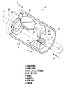
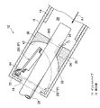
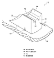
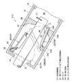
図1及び図2には、本発明の第一実施形態の燃料タンクの給油部構造(以下、単に「給油部構造」とする)12が示されている。図1から分かるように、本実施形態では、給油口を閉塞するためのキャップが不要とされており、いわゆるキャップレスの構造となっている。   1 and 2 show a fuel tank fueling part structure (hereinafter, simply referred to as “fueling part structure”) 12 of a fuel tank according to a first embodiment of the present invention. As can be seen from FIG. 1, in the present embodiment, a cap for closing the fuel filler opening is unnecessary, and a so-called capless structure is formed.

給油部構造12は、インレットパイプ14の上部に設けられている。インレットパイプ14の下端は、図示しない燃料タンクに接続されている。   The oil supply portion structure 12 is provided on the upper portion of the inlet pipe 14. The lower end of the inlet pipe 14 is connected to a fuel tank (not shown).

インレットパイプ14の上端には、略円筒状の給油口部材16が構成されている。給油口部材16の内部が給油口26(その中心を中心線CLで示す)となっており、上端の開口部18から給油ガン28を給油口26に挿入して、燃料タンクに給油することが可能とされている。   A substantially cylindrical oil filler member 16 is formed at the upper end of the inlet pipe 14. The inside of the fuel filler member 16 is a fuel filler 26 (the center of which is indicated by the center line CL), and a fuel gun 28 is inserted into the fuel filler 26 from the opening 18 at the upper end to supply fuel to the fuel tank. It is possible.

給油口部材16の上部、すなわち給油口26の開口部18には、フラッパバルブ20が配置されている。フラッパバルブ20は、その上部に設けられたヒンジ22によって、給油口部材16に回動可能に取り付けられている。そして、フラッパバルブ20は、給油口26を閉塞する閉塞位置TP(二点鎖線で示す位置)と、給油口26を開放する開放位置HP(実線で示す位置)との間を回動する。開放位置HPでは、フラッパバルブ20の下部、すなわちヒンジ22が配置された側と反対側が、燃料タンク側に大きく移動している。   A flapper valve 20 is arranged at the upper portion of the fuel filler member 16, that is, at the opening 18 of the fuel filler port 26. The flapper valve 20 is rotatably attached to the fuel filler member 16 by a hinge 22 provided on the upper portion thereof. Then, the flapper valve 20 rotates between a closing position TP (a position indicated by a two-dot chain line) that closes the fuel inlet 26 and an open position HP (a position indicated by a solid line) that opens the fuel inlet 26. In the open position HP, the lower part of the flapper valve 20, that is, the side opposite to the side where the hinge 22 is arranged has moved greatly to the fuel tank side.

なお、給油口部材16の内面には図示しないストッパ突起が形成されており、フラッパバルブ20の回動範囲(開放位置)が所定範囲に制限されている。また、ヒンジ22には、フラッパバルブ用バネ44が巻きかけられている。フラッパバルブ用バネ44は、フラッパバルブ20を閉塞位置TPに向かって付勢しており、不用意に給油口26が開放されないようになっている。フラッパバルブ20は、開口部18から挿入した給油ガン28によって押されると、フラッパバルブ用バネ44の付勢力に抗して、開放位置HPへと移動(回動)する。   A stopper protrusion (not shown) is formed on the inner surface of the fuel filler member 16, and the rotation range (open position) of the flapper valve 20 is limited to a predetermined range. Further, a flapper valve spring 44 is wound around the hinge 22. The flapper valve spring 44 urges the flapper valve 20 toward the closing position TP so that the oil supply port 26 is not inadvertently opened. When the flapper valve 20 is pushed by the fuel gun 28 inserted from the opening 18, the flapper valve 20 moves (rotates) to the open position HP against the urging force of the flapper valve spring 44.

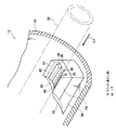
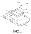
図3にも詳細に示すように、給油口部材16の内面には、給油口26に挿入された給油ガン28の外周面に下側から接触する拭い取り部材24が設けられている。本実施形態では、給油口部材16の内周側に位置する固定台座30が固定されており、拭い取り部材24は、この固定台座30に固定されている。なお、拭い取り部材24を固定台座30と一体化してもよい。   As shown in detail in FIG. 3, a wiping member 24 is provided on the inner surface of the fuel filler member 16 so as to contact the outer peripheral surface of the fuel gun 28 inserted into the fuel filler 26 from below. In the present embodiment, the fixed base 30 located on the inner peripheral side of the fuel filler member 16 is fixed, and the wiping member 24 is fixed to the fixed base 30. Note that the wiping member 24 may be integrated with the fixed base 30.

固定台座30と拭い取り部材24は、いずれも、フラッパバルブ20側(開口部18側)にテーパー面32が形成されている。テーパー面32は、給油ガン28が挿入時に接触すると、給油ガン28を給油口26の中心(中心線CL)に案内する。   Each of the fixed base 30 and the wiping member 24 has a tapered surface 32 on the flapper valve 20 side (opening 18 side). The tapered surface 32 guides the oil supply gun 28 to the center (center line CL) of the oil supply port 26 when the oil supply gun 28 comes into contact with the taper surface 32 during insertion.

拭い取り部材24の上面は、給油ガン28の外周面(表面)に接触する接触面34とされている。特に、拭い取り部材24を矢印A1方向(給油ガン28を給油口26から抜く方向)に見たとき、接触面34の曲率半径は給油ガン28の外周面の曲率半径と等しくなっており、接触面34は給油ガン28の外周面に面接触するように湾曲されている。給油ガン28の外周面が接触面34に接触した状態で給油ガン28が給油口26から抜かれると、接触面34は、給油ガン28の外周面に面接触しているので、この外周面に付着した燃料の一部を拭い取る作用を有している。   The upper surface of the wiping member 24 is a contact surface 34 that contacts the outer peripheral surface (surface) of the fuel gun 28. In particular, when the wiping member 24 is viewed in the direction of arrow A1 (the direction in which the fueling gun 28 is pulled out from the fueling port 26), the radius of curvature of the contact surface 34 is equal to the radius of curvature of the outer peripheral surface of the fueling gun 28. The surface 34 is curved so as to make surface contact with the outer peripheral surface of the fuel gun 28. When the fuel gun 28 is pulled out from the fuel filler port 26 in a state where the outer peripheral surface of the fuel gun 28 is in contact with the contact surface 34, the contact surface 34 is in surface contact with the outer peripheral surface of the fuel gun 28. It has an effect of wiping off a part of the attached fuel.

拭い取り部材24には、接触面34側から複数のスリット38が形成されており、スリット38以外の部分が複数のリブ40となっている。スリット38には、給油ガン28の外周面が接触面34によって拭い取られた燃料が一時的に流れ込む。すなわち、スリット38は、給油ガン28の外周面から拭い取られた燃料を一時的に収容することで、効果的な拭い取りが可能をしている。スリット38は、本発明に逃がし部の一例である。   A plurality of slits 38 are formed in the wiping member 24 from the contact surface 34 side, and portions other than the slits 38 are a plurality of ribs 40. The fuel in which the outer peripheral surface of the fuel gun 28 is wiped off by the contact surface 34 temporarily flows into the slit 38. That is, the slit 38 temporarily stores the fuel wiped off from the outer peripheral surface of the fuel supply gun 28, thereby enabling effective wiping. The slit 38 is an example of an escape portion in the present invention.

本実施形態では、スリット38の長手方向が、給油ガン28を給油口26から抜く方向(矢印A1方向)に沿っており、給油口26の奥側及び手前側ではスリット38は開放されている。このため、スリット38に収容された燃料はスリット38内を移動し、この開放部分からスリット38外(給油口26内)に流れ出る。   In the present embodiment, the longitudinal direction of the slit 38 is along the direction (arrow A1 direction) in which the fueling gun 28 is pulled out from the fueling port 26, and the slit 38 is open on the back side and the near side of the fueling port 26. For this reason, the fuel accommodated in the slit 38 moves in the slit 38 and flows out from the open portion to the outside of the slit 38 (inside the fuel filler opening 26).

図1及び図2に示すように、給油口部材16の内面には、拭い取り部材24に対し、挿入された給油ガン28を挟んで対向する位置に、案内凸部36が形成されている。案内凸部36は、その下面の中央部分が、給油ガン28と同様の曲率で円弧状に湾曲した案内面36Sとされている。   As shown in FIGS. 1 and 2, a guide convex portion 36 is formed on the inner surface of the fuel filler member 16 at a position facing the wiping member 24 with the inserted fuel gun 28 interposed therebetween. The guide convex portion 36 has a guide portion 36 </ b> S whose central portion on the lower surface is curved in an arc shape with the same curvature as the fuel gun 28.

案内凸部36にも、フラッパバルブ20側(開口部18側)に、給油口26への給油ガン28の挿入時に、給油ガン28を給油口26の中心(中心線CL)に案内するテーパー面42が形成されている。   The guide convex portion 36 also has a tapered surface on the flapper valve 20 side (opening portion 18 side) that guides the fuel gun 28 to the center (center line CL) of the fuel port 26 when the fuel gun 28 is inserted into the fuel port 26. 42 is formed.

次に、本実施形態の給油部構造12の作用を説明する。   Next, the effect | action of the oil supply part structure 12 of this embodiment is demonstrated.

通常は、図1に二点鎖線で示すように、フラッパバルブ20が、フラッパバルブ用バネの付勢力を受けて閉塞位置TPを維持しており、給油口26は閉塞されている。   Normally, as indicated by a two-dot chain line in FIG. 1, the flapper valve 20 receives the biasing force of the flapper valve spring to maintain the closed position TP, and the fuel supply port 26 is closed.

給油時には、給油ガン28を給油口26に差し入れる。フラッパバルブ用バネ44の付勢力は給油ガン28から作用する押圧力よりも小さく設定されており、給油ガン28に押されたフラッパバルブ20が開放位置HPへと回動するので、給油ガン28をさらに奥へと挿入することができる。   When refueling, the refueling gun 28 is inserted into the refueling port 26. The biasing force of the flapper valve spring 44 is set to be smaller than the pressing force applied from the fuel gun 28, and the flapper valve 20 pushed by the fuel gun 28 rotates to the open position HP. It can be inserted further into the back.

給油ガン28の挿入途中で、給油ガン28の先端がテーパー面32及びテーパー面42のいずれか一方に接触することがある。この状態でさらに給油ガン28を給油口26の奥に差し入れると、テーパー面32又はテーパー面42によって給油ガン28が給油口26の中心に向かって案内される。所定位置まで給油ガン28を挿入した状態で、給油を行うことができる。また、給油ガン28を給油口26の所定位置まで挿入して給油している状態では、接触面34が給油ガン28に接触しており、給油ガン28が安定的に支持される。   During the insertion of the fuel gun 28, the tip of the fuel gun 28 may come into contact with either the tapered surface 32 or the tapered surface 42. In this state, when the fueling gun 28 is further inserted into the interior of the fueling port 26, the fueling gun 28 is guided toward the center of the fueling port 26 by the tapered surface 32 or the tapered surface 42. Refueling can be performed with the fuel gun 28 inserted to a predetermined position. Further, in a state where the fueling gun 28 is inserted to a predetermined position of the fueling port 26 and fueled, the contact surface 34 is in contact with the fueling gun 28 and the fueling gun 28 is stably supported.

給油ガン28を給油口26から引き抜くときには、給油ガン28の外周面に接触面34が接触した状態が維持されながら、給油ガン28が引き抜かれる。このため、給油ガン28の外周面に燃料が付着していても、この燃料の少なくとも一部が接触面34によって拭い取られ、給油ガン28の外周面から除去される。このため、給油ガン28に付着した燃料が、給油口26の外部(たとえば車体のパネル)等を流れ落ちること(いわゆる液垂れ)を抑制できる。特に、第1実施形態では、拭い取り部材24は、給油口部材16に対し固定されているので、給油ガン28の外周面に対する接触面34の接触状態を安定的に維持できる。   When the fueling gun 28 is pulled out from the fueling port 26, the fueling gun 28 is pulled out while maintaining the state where the contact surface 34 is in contact with the outer peripheral surface of the fueling gun 28. For this reason, even if fuel adheres to the outer peripheral surface of the fuel gun 28, at least a part of the fuel is wiped off by the contact surface 34 and removed from the outer peripheral surface of the fuel gun 28. For this reason, it is possible to suppress the fuel adhering to the fuel supply gun 28 from flowing down outside the fuel supply port 26 (for example, a panel of the vehicle body) (so-called liquid dripping). In particular, in the first embodiment, since the wiping member 24 is fixed to the fuel filler port member 16, the contact state of the contact surface 34 with the outer peripheral surface of the fuel gun 28 can be stably maintained.

しかも、第1実施形態では、拭い取り部材24は給油口26の下側に位置しており、接触面34は、給油口26に挿入された給油ガン28に対し下側から接触している。給油ガン28の外周面では、燃料は重力により下方に付着しやすいが、接触面34が給油ガン28の外周面に下方から接触するので、効果的に燃料を拭い取ることができる。   Moreover, in the first embodiment, the wiping member 24 is located below the fuel filler 26, and the contact surface 34 is in contact with the fuel gun 28 inserted into the fuel filler 26 from below. On the outer peripheral surface of the fuel gun 28, the fuel tends to adhere downward due to gravity. However, since the contact surface 34 contacts the outer peripheral surface of the fuel gun 28 from below, the fuel can be effectively wiped off.

加えて、第1実施形態では、拭い取り部材24に接触面34にスリット38を形成しており、拭い取った燃料の一部はこのスリット38内に雫状に落下して収容される。したがって、給油ガン28を給油口から引き抜く動作において、効果的に給油ガン28の外周面から燃料を拭い取ることができる。スリット38内に収容された燃料(拭い取られた燃料)は、スリット38の奥側又は手前側の開放部分から給油口26内に流出する。   In addition, in the first embodiment, a slit 38 is formed on the contact surface 34 of the wiping member 24, and a part of the wiped fuel is dropped into the slit 38 and accommodated. Therefore, in the operation of pulling out the fuel gun 28 from the fuel filler port, the fuel can be effectively wiped from the outer peripheral surface of the fuel gun 28. The fuel contained in the slit 38 (the wiped fuel) flows out into the fuel filler opening 26 from the open part on the back side or the near side of the slit 38.

なお、給油ガン28を給油口26から完全に引き抜くと、フラッパバルブ用バネ44の付勢力で、図1に二点鎖線で示すようにフラッパバルブ20が閉塞位置TPへ回動し、給油口26を閉塞する。   When the fueling gun 28 is completely pulled out from the fueling port 26, the flapper valve 20 is rotated to the closed position TP as shown by a two-dot chain line in FIG. Occlude.

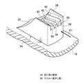
図4には、第1実施形態の第1変形例の給油部構造に適用される拭い取り部材54が拡大して示されている。第1変形例の拭い取り部材54はが固定台座30と一体化されている。また、第1変形例の拭い取り部材54では、接触面34に形成されたスリット58の形状が第1実施形態と異なっているが、これ以外は同一の構成である。   FIG. 4 shows an enlarged view of the wiping member 54 applied to the oil supply portion structure of the first modification of the first embodiment. The wiping member 54 of the first modification is integrated with the fixed base 30. Further, in the wiping member 54 of the first modified example, the shape of the slit 58 formed on the contact surface 34 is different from that of the first embodiment, but the other configuration is the same.

すなわち、第1変形例のスリット58は、図5にも詳細に示すように、長手方向の全体あるいは一部(図5に示す例では長手方向の中間部分)が、給油ガン28の引き抜き方向(矢印A1方向)に対し傾斜している。そして、矢印A1方向に見ると、スリット58による隙間が生じないようになっている。たとえば、スリット58内に、矢印A1と平行な任意の補助線A2を想定すると、補助線A2がスリット58の一端側から他端側(図5における右側から左側)に突き抜けることはない。換言すれば、給油ガン28の外周面が接触面34に接触した状態で矢印A1方向に移動すると、給油ガン28の外周面の周方向では、接触面34が広い範囲(隙間の無い範囲)で確実に給油ガン28の外周面に接触し、燃料を拭い取ることができる。   That is, as shown in detail in FIG. 5, the slit 58 of the first modification is entirely or partially in the longitudinal direction (in the example shown in FIG. 5, an intermediate portion in the longitudinal direction). It is inclined with respect to the direction of arrow A1. Then, when viewed in the direction of the arrow A1, a gap due to the slit 58 is not generated. For example, assuming an arbitrary auxiliary line A2 parallel to the arrow A1 in the slit 58, the auxiliary line A2 does not penetrate from the one end side of the slit 58 to the other end side (the right side to the left side in FIG. 5). In other words, when the outer peripheral surface of the fuel gun 28 is in contact with the contact surface 34 and moves in the direction of the arrow A1, the contact surface 34 is wide in the circumferential direction of the outer peripheral surface of the fuel gun 28 (range without a gap). The fuel can be wiped off by reliably contacting the outer peripheral surface of the fuel supply gun 28.

図6には、第1実施形態の第2変形例の給油部構造に適用される拭い取り部材64が拡大して示されている。第2変形例の拭い取り部材64においても、拭い取り部材64が固定台座30と一体化されている。そして、接触面34に形成されたスリット68が第1実施形態のスリット38よりも幅広で、且つスリット68の数は、第1実施形態よりも少なくなっているが、これ以外は同一の構成である。   FIG. 6 shows an enlarged view of the wiping member 64 applied to the oil supply portion structure of the second modification of the first embodiment. Also in the wiping member 64 of the second modified example, the wiping member 64 is integrated with the fixed base 30. The slits 68 formed on the contact surface 34 are wider than the slits 38 of the first embodiment, and the number of slits 68 is smaller than that of the first embodiment. is there.

したがって、第2変形例においても、給油ガン28の外周面から拭い取ったスリット68に燃料をスリット68に収容することができる。第2変形例では、リブ70が第1実施形態のリブ40と比較して厚肉になるので、給油ガン28の外周面が接触面34に接触した状態でのリブ40の不用意な変形を抑制できる。   Therefore, also in the second modification, the fuel can be accommodated in the slit 68 in the slit 68 wiped from the outer peripheral surface of the fuel gun 28. In the second modification, the rib 70 is thicker than the rib 40 of the first embodiment, so that the rib 40 is inadvertently deformed when the outer peripheral surface of the fuel gun 28 is in contact with the contact surface 34. Can be suppressed.

なお、これに対し、第1実施形態では、スリット38が第2変形例よりも幅狭であり、この幅を適切に設定することで、燃料に表面張力を作用させて、燃料に対するスリット38の吸収性を高めることが可能である。   In contrast, in the first embodiment, the slit 38 is narrower than the second modification, and by setting this width appropriately, surface tension is applied to the fuel, and the slit 38 with respect to the fuel Absorbability can be increased.

図7には、本発明の第2実施形態の給油部構造112が部分的に拡大して示されている。第2実施形態において、第1実施形態と同一の構成要素、部材等については同一符号を付して、詳細な説明を省略する。また、給油部構造112の全体的構成は、第1実施形態の給油部構造12と略同一であるので、図示を省略する。   FIG. 7 shows a partially enlarged view of the oil supply portion structure 112 according to the second embodiment of the present invention. In the second embodiment, the same components and members as those in the first embodiment are denoted by the same reference numerals, and detailed description thereof is omitted. Moreover, since the whole structure of the oil supply part structure 112 is substantially the same as the oil supply part structure 12 of 1st Embodiment, illustration is abbreviate | omitted.

第2実施形態の給油部構造112では、拭い取り部材124の接触面134が、第1実施形態の接触面34と同様に、給油口26に挿入された給油ガン28の外周面に面接触可能な湾曲形状とされているが、第1実施形態に係るスリット38(図3参照)は形成されていない。   In the fuel filler structure 112 of the second embodiment, the contact surface 134 of the wiping member 124 can be in surface contact with the outer peripheral surface of the fuel gun 28 inserted into the fuel filler port 26 in the same manner as the contact surface 34 of the first embodiment. However, the slit 38 (see FIG. 3) according to the first embodiment is not formed.

また、固定台座30と拭い取り部材124の間に間隙が構成されており、この間隙に、矢印B1方向に見て略横U字状の板バネ138が配置されている。板バネ138は、拭い取り部材124を所定位置で保持しており、接触面134は、第1実施形態における接触面34よりも、わずかに中心線CLに近い位置となっている。   Further, a gap is formed between the fixed base 30 and the wiping member 124, and a substantially horizontal U-shaped leaf spring 138 is disposed in this gap when viewed in the direction of the arrow B1. The leaf spring 138 holds the wiping member 124 at a predetermined position, and the contact surface 134 is slightly closer to the center line CL than the contact surface 34 in the first embodiment.

したがって、給油口26に給油ガン28が挿入されると、接触面34が給油ガン28の外周面に押されて中心線CLから離間する方向にわずかに移動する。そして、板バネ138が弾性変形することで、拭い取り部材124に、中心線CLに向かう方向の付勢力を作用させる。第2実施形態では、固定台座30と板バネ138によって、本発明に係る押圧支持部材が構成されている。   Therefore, when the fueling gun 28 is inserted into the fueling port 26, the contact surface 34 is pushed by the outer peripheral surface of the fueling gun 28 and slightly moves away from the center line CL. And the urging | biasing force of the direction which goes to the centerline CL is made to act on the wiping member 124 because the leaf | plate spring 138 elastically deforms. In the second embodiment, the fixed pedestal 30 and the leaf spring 138 constitute a pressing support member according to the present invention.

なお、板バネ138にも、フラッパバルブ20側(開口部18側)にテーパー面32が形成されている。   The leaf spring 138 also has a tapered surface 32 on the flapper valve 20 side (opening 18 side).

このような構成とされた第2実施形態の給油部構造112においても、第1実施形態の給油部構造12と同様の作用効果を奏する。   Also in the oil supply part structure 112 of 2nd Embodiment set as such a structure, there exists an effect similar to the oil supply part structure 12 of 1st Embodiment.

特に第2実施形態の給油部構造112では、給油ガン28を給油口26から引き抜くときに給油ガン28が上下方向(矢印C1方向)に移動しても、板バネ138の付勢力が拭い取り部材24に作用することで、接触面34が給油ガン28の外周面に接触した状態を維持可能となる。   In particular, in the oil supply portion structure 112 of the second embodiment, when the oil supply gun 28 is pulled out from the oil supply port 26, even if the oil supply gun 28 moves in the vertical direction (arrow C1 direction), the urging force of the leaf spring 138 is a wiping member. By acting on 24, the contact surface 34 can be kept in contact with the outer peripheral surface of the fuel gun 28.

また、給油ガン28が矢印A1方向に移動しない場合でも、板バネ138の付勢力で接触面34を給油ガン28の外周面に押圧できるので、給油ガン28の外周面からより確実に燃料を拭い取ることが可能となる。   Further, even when the fuel gun 28 does not move in the direction of the arrow A1, the contact surface 34 can be pressed against the outer peripheral surface of the fuel gun 28 by the urging force of the leaf spring 138, so that the fuel can be wiped more reliably from the outer peripheral surface of the fuel gun 28. It becomes possible to take.

図8には、本発明の第3実施形態の給油部構造212が示されている。第3実施形態において、第1実施形態又は第2実施形態と同一の構成要素、部材等については同一符号を付して、詳細な説明を省略する。   FIG. 8 shows an oil supply portion structure 212 according to the third embodiment of the present invention. In the third embodiment, the same components and members as those in the first embodiment or the second embodiment are denoted by the same reference numerals, and detailed description thereof is omitted.

第3実施形態の給油部構造212では、第1実施形態の固定台座30(図1〜図3参照)は設けられておらず、これに代えて、第2フラッパバルブ220が設けられている。第2フラッパバルブ220は、その下部に設けられたヒンジ222により、給油口部材16に回動可能に取り付けられている。そして、回動により、二点鎖線で示す起立位置SPと、実線で示す横臥位置DPとの間を回動する。なお、フラッパバルブ20の回動軌跡と第2フラッパバルブ220の回動軌跡とは重ならないようになっている。   In the oil supply portion structure 212 of the third embodiment, the fixed base 30 (see FIGS. 1 to 3) of the first embodiment is not provided, and a second flapper valve 220 is provided instead. The second flapper valve 220 is rotatably attached to the fuel filler member 16 by a hinge 222 provided at a lower portion thereof. And by rotation, it rotates between standing position SP shown with a dashed-two dotted line, and recumbent position DP shown with a continuous line. Note that the rotation locus of the flapper valve 20 and the rotation locus of the second flapper valve 220 do not overlap.

ヒンジ222には第2フラッパバルブ用バネ244が装着されており、第2フラッパバルブ220を起立位置SPに向かって回動付勢している。第2フラッパバルブ220の回動は、横臥位置ではストッパ238に当たって制限され、同様に、起立位置SPにおいても、図示しないストッパに当たって制限される。また、給油口部材16には、起立位置SPにある第2フラッパバルブ20に接触して給油口26を閉塞するために、図示しない閉塞部材が形成されている。   A second flapper valve spring 244 is attached to the hinge 222 and urges the second flapper valve 220 to rotate toward the standing position SP. The rotation of the second flapper valve 220 is limited by hitting the stopper 238 in the recumbent position, and similarly, the rotation of the second flapper valve 220 is also limited by hitting a stopper (not shown) in the standing position SP. Further, a closing member (not shown) is formed in the fuel filler member 16 so as to contact the second flapper valve 20 in the standing position SP and close the fuel filler port 26.

第2フラッパバルブ220には、回動先端側(ヒンジ222の反対側)で、且つ横臥位置DPにおける中心線CL側の位置に、拭い取り部材224が設けられている。拭い取り部材224には、第1実施形態の拭い取り部材24や第2実施形態の拭い取り部材124と同様に、給油口26に挿入された給油ガン28の外周面に面接触する接触面34が形成されている。拭い取り部材224は、第2フラッパバルブ220が横臥位置DPにあるとき、給油ガン28を挟んで案内凸部36と対向している。第3実施形態では、第2フラッパバルブ220と第2フラッパバルブ用バネ244によって、本発明に係る押圧支持部材が構成されている。   The second flapper valve 220 is provided with a wiping member 224 on the rotation tip side (opposite side of the hinge 222) and on the center line CL side in the recumbent position DP. Similar to the wiping member 24 of the first embodiment and the wiping member 124 of the second embodiment, the wiping member 224 has a contact surface 34 that makes surface contact with the outer peripheral surface of the fuel gun 28 inserted into the fuel filler port 26. Is formed. The wiping member 224 faces the guide convex portion 36 with the fuel gun 28 interposed therebetween when the second flapper valve 220 is in the recumbent position DP. In the third embodiment, the second flapper valve 220 and the second flapper valve spring 244 constitute a pressing support member according to the present invention.

このような構成とされた第3実施形態の給油部構造212では、通常は、フラッパバルブ20に加えて、第2フラッパバルブ220によって給油口26が二重に閉塞されている。   In the oil supply portion structure 212 of the third embodiment having such a configuration, the oil supply port 26 is normally double-closed by the second flapper valve 220 in addition to the flapper valve 20.

給油ガン28を給油口26に差し入れると、まず、フラッパバルブ20が給油ガン28に押されて開放位置HPとなり、次に、第2フラッパバルブ220が給油ガン28に押されて横臥位置DPとなる。これにより、給油口26が開放され、給油を行うことができる。給油ガン28の挿入途中では、給油ガン28の先端がテーパー面32又はテーパー面42に接触すると給油ガン28が給油口26の中心に案内される。   When the fueling gun 28 is inserted into the fueling port 26, first, the flapper valve 20 is pushed by the fueling gun 28 to the open position HP, and then the second flapper valve 220 is pushed by the fueling gun 28 to reach the recumbent position DP. Become. As a result, the fuel filler port 26 is opened and fuel can be supplied. In the middle of insertion of the fuel gun 28, when the tip of the fuel gun 28 contacts the tapered surface 32 or the tapered surface 42, the fuel gun 28 is guided to the center of the fuel inlet 26.

給油ガン28を給油口26から引き抜くときは、給油ガン28の外周面に接触面34が接触した状態が維持されるので、給油ガン28の外周面に付着した燃料も一部が接触面34によって拭い取られ、給油ガン28の外周面から除去され、いわゆる液垂れを抑制できる。   When the fueling gun 28 is pulled out from the fueling port 26, the contact surface 34 is maintained in contact with the outer peripheral surface of the fueling gun 28, so that part of the fuel adhering to the outer peripheral surface of the fueling gun 28 is also contacted by the contact surface 34. It is wiped off and removed from the outer peripheral surface of the fuel gun 28, so-called dripping can be suppressed.

しかも、第3実施形態では、コイルバネの回転付勢力によって第2フラッパバルブ220が横臥位置DPから起立位置SPに向かって付勢されているので、接触面34にも給油ガン28の外周面への押圧力が作用する。このため、給油ガン28を給油口26から引き抜くときに給油ガン28が上下方向(矢印C1方向)に移動しても、接触面34が給油ガン28の外周面に接触した状態を維持可能となる。また、給油ガン28が矢印C1方向に移動しない場合でも、板バネ138の付勢力で接触面34を給油ガン28の外周面に押圧し、給油ガン28の外周面からより確実に燃料を拭い取ることが可能となる。   Moreover, in the third embodiment, the second flapper valve 220 is urged from the recumbent position DP toward the standing position SP by the rotational urging force of the coil spring, so that the contact surface 34 is also applied to the outer peripheral surface of the fuel gun 28. A pressing force acts. For this reason, even when the oil supply gun 28 moves in the vertical direction (arrow C1 direction) when the oil supply gun 28 is pulled out from the oil supply port 26, the contact surface 34 can be kept in contact with the outer peripheral surface of the oil supply gun 28. . Further, even when the fuel gun 28 does not move in the direction of the arrow C 1, the contact surface 34 is pressed against the outer peripheral surface of the fuel gun 28 by the urging force of the leaf spring 138, and the fuel is more reliably wiped off from the outer peripheral surface of the fuel gun 28. It becomes possible.

なお、第3実施形態において、フラッパバルブ20のみによって給油口26を閉塞することも可能であるため、この場合には、第2フラッパバルブ220が、起立位置SPにおいて給油口20を閉塞する作用を有していなくてもよい。   In the third embodiment, it is possible to close the fuel filler port 26 only by the flapper valve 20, and in this case, the second flapper valve 220 acts to close the fuel filler port 20 at the standing position SP. It may not have.

また、上記第2実施形態及び第3実施形態において、第1実施形態と同様に、接触面34にスリット38、58、68等を形成してもよい。ただし、第2実施形態及び第3実施形態では、板バネ138あるいはコイルバネ238の付勢力が拭い取り部材124、224に作用するので、スリット38、58、68等を形成したことでリブ40があまりに薄肉になると、リブ40が給油ガン28の外周面に押圧されて倒れ込みやすくなる。したがって、このような倒れ込みを抑制可能となるようにリブが十分な幅を有していることが好ましい。もちろん、これとは逆に、第1実施形態の拭い取り部材24において、スリット38を形成しなくてもよい。   In the second embodiment and the third embodiment, slits 38, 58, 68 and the like may be formed on the contact surface 34 as in the first embodiment. However, in the second and third embodiments, the urging force of the leaf spring 138 or the coil spring 238 acts on the wiping members 124, 224, so that the ribs 40 are formed too much by forming the slits 38, 58, 68, etc. When it becomes thin, the rib 40 is pressed against the outer peripheral surface of the fuel gun 28 and easily falls down. Therefore, it is preferable that the rib has a sufficient width so that such a fall can be suppressed. Of course, on the contrary, the slit 38 does not need to be formed in the wiping member 24 of the first embodiment.

本発明の逃がし部は、これらのスリット38、58、68等に限定されず、要するに、給油ガン28の外周面から拭い取った燃料を、この外周面から離間した位置に逃がすことで、給油ガン28への燃料の再付着を抑制することが可能であればよい。たとえば、接触面34に形成された1又は複数の窪み(凹部)と、この窪みに溜まった燃料を窪みのそれぞれから排出させる排出流路あるいは流出孔を備えた構造でもよい。   The escape portion of the present invention is not limited to these slits 38, 58, 68, etc. In short, the fuel that has been wiped off from the outer peripheral surface of the fuel gun 28 is allowed to escape to a position away from this outer peripheral surface. What is necessary is just to be able to suppress the reattachment of the fuel to 28. For example, a structure including one or a plurality of depressions (recesses) formed in the contact surface 34 and a discharge flow path or an outflow hole for discharging the fuel accumulated in the depressions from each of the depressions may be used.

また、上記各実施形態では、フラッパバルブ20よりも給油口26の奥側に拭い取り部材を設けた構造のものを例に挙げているが、フラッパバルブ20よりも手前側に拭い取り部材24が設けられていてもよい。各実施形態のようにフラッパバルブ20よりも奥側に拭い取り部材24を設けると、フラッパバルブ20への燃料の付着(給油ガン28からの転移)を抑制できる。   Moreover, in each said embodiment, although the thing of the structure which provided the wiping member in the back | inner side of the fuel filler opening 26 rather than the flapper valve 20 is mentioned as an example, the wiping member 24 is located in front of the flapper valve 20. It may be provided. If the wiping member 24 is provided on the back side of the flapper valve 20 as in each embodiment, the adhesion of fuel to the flapper valve 20 (transfer from the fuel gun 28) can be suppressed.

拭い取り部材24、124、224は、給油口26から引き抜かれる給油ガン28の外周面に対し、下側から接触する構造のものに限らず、たとえば、給油ガン28の表面の全周にわたって接触する構造でもよい。さらに、給油ガン28の外周面に上側から接触しても、接触した部分では燃料を拭い取ることができる。   The wiping members 24, 124, and 224 are not limited to those having a structure that comes into contact with the outer peripheral surface of the fuel gun 28 pulled out from the fuel filler port 26 from the lower side, and, for example, contact over the entire circumference of the surface of the fuel gun 28. It may be a structure. Furthermore, even if it contacts the outer peripheral surface of the fuel gun 28 from above, the fuel can be wiped off at the contacted portion.

拭い取り部材24、124、224の材質は、給油ガン28の外周面との接触性を良好に維持して、燃料を拭い取ることが可能であれば特に限定されないが、スリット38を形成しない拭い取り部材の場合は、たとえば樹脂、ゴムあるいはエラストマーを適用できる。スリット38を形成した拭い取り部材であっても、リブ40に所定の剛性を確保可能であれば、これらの樹脂、ゴムあるいはエラストマーを適用可能である。特に、ゴムやエラストマーでは、一般的に燃料が接触したときの接触角が大きくなり、燃料によって拭い取り部材が濡れない(燃料が拭い取り部材にはじかれる)ので、拭い取り部材の燃料切れが良くなる。   The material of the wiping members 24, 124, and 224 is not particularly limited as long as the fuel can be wiped off while maintaining good contact with the outer peripheral surface of the fuel gun 28, but the wiping that does not form the slit 38 is possible. In the case of a take-off member, for example, resin, rubber or elastomer can be applied. Even with the wiping member in which the slit 38 is formed, these resins, rubbers, or elastomers can be applied as long as the rib 40 can have a predetermined rigidity. In particular, with rubber and elastomer, the contact angle when the fuel comes into contact generally increases, and the wiping member does not get wet by the fuel (the fuel is repelled by the wiping member), so that the wiping member runs out of fuel well. Become.

本発明の開閉弁としては、上記したフラッパバルブ20に限定されず、給油口を確実に開閉できるものであればよい。フラッパバルブ20を用いた構造において、ヒンジ22の位置も限定されず、たとえばフラッパバルブ20の下部にヒンジ22を設けて、いわゆる下開きのフラッパバルブとしてもよい。このような下開きのフラッパバルブでは、フラッパバルブよりも奥側に拭い取り部材24、124、224を設けて、給油ガン28からフラッパバルブへの燃料の転移(付着)を抑制することが好ましい。   The opening / closing valve of the present invention is not limited to the flapper valve 20 described above, and may be any valve that can reliably open and close the fuel filler opening. In the structure using the flapper valve 20, the position of the hinge 22 is not limited. For example, the hinge 22 may be provided in the lower part of the flapper valve 20 to form a so-called downwardly opened flapper valve. In such an open flapper valve, it is preferable to provide wiping members 24, 124, and 224 on the back side of the flapper valve to suppress the transfer (attachment) of fuel from the fuel supply gun 28 to the flapper valve.

さらに、フラッパバルブ20等の開閉弁を有さない給油部(たとえばキャップ等で開閉される構造)に本発明を適用することも可能である。   Furthermore, the present invention can be applied to an oil supply portion (for example, a structure that is opened and closed by a cap or the like) that does not have an opening / closing valve such as the flapper valve 20.

12 給油部構造
14 インレットパイプ
16 給油口部材
18 開口部
20 フラッパバルブ(開閉弁)
24 拭い取り部材
26 給油口
28 給油ガン
30 固定台座
34 接触面
38 スリット(逃がし部)
40 リブ
54 拭い取り部材
58 スリット(逃がし部)
64 拭い取り部材
68 スリット(逃がし部)
70 リブ
112 給油部構造
124 拭い取り部材
134 接触面
138 板バネ(押圧支持部材)
212 給油部構造
220 第2フラッパバルブ(押圧支持部材)
222 ヒンジ
224 拭い取り部材
238 コイルバネ(押圧支持部材)
12 Oil Supply Structure 14 Inlet Pipe 16 Oil Supply Port Member 18 Opening 20 Flapper Valve (Open / Close Valve)
24 Wiping member 26 Refueling port 28 Refueling gun 30 Fixed base 34 Contact surface 38 Slit (relief part)
40 Rib 54 Wiping member 58 Slit (Relief part)
64 Wiping member 68 Slit (relief part)
70 Rib 112 Oil Supply Part Structure 124 Wiping Member 134 Contact Surface 138 Leaf Spring (Pressing Support Member)
212 Oil supply part structure 220 Second flapper valve (pressing support member)
222 Hinge 224 Wiping member 238 Coil spring (pressing support member)

Claims (5)

燃料タンクへの給油用の給油ガンが挿入される給油口を構成する給油口部材と、
前記給油口部材の内部に設けられ、前記給油ガンが前記給油口から引き抜かれるときに給油ガンに接触して給油ガン表面の燃料を拭い取る拭い取り部材と、
を有する燃料タンクの給油部構造
A filler port member constituting a filler port into which a fuel gun for fueling a fuel tank is inserted; and
A wiping member that is provided inside the fuel filler member and that wipes off fuel on the surface of the fuel gun by contacting the fuel gun when the fuel gun is pulled out from the fuel filler;
Structure of fuel tank having fuel tank
前記給油口を開閉可能な開閉弁を備え、
前記拭い取り部材が前記開閉弁よりも前記給油口の奥側に配置されている請求項1に記載の燃料タンクの給油部構造。
An on-off valve capable of opening and closing the fuel filler opening;
2. The fuel tank fueling portion structure according to claim 1, wherein the wiping member is disposed on a deeper side of the fuel filler opening than the on-off valve.
前記拭い取り部材に、前記給油ガンから拭い取った燃料が給油ガンに再付着しないように該燃料を給油ガン表面から離間した位置に逃がす逃がし部が形成されている請求項1又は請求項2に記載の燃料タンクの給油部構造。   The wiping member is formed with an escape portion for allowing the fuel wiped off from the fuel gun to escape from the surface of the fuel gun so that the fuel does not reattach to the fuel gun. The fuel tank fueling part structure described. 前記拭い取り部材が前記給油口部材に固定されている請求項1〜請求項3のいずれか1項に記載の燃料タンクの給油部構造。   The fuel supply part structure of a fuel tank according to any one of claims 1 to 3, wherein the wiping member is fixed to the fuel supply port member. 前記給油口部材に設けられ、前記拭い取り部材を前記給油口に挿入された給油ガンの外周面に押圧可能に支持する押圧支持部材、を有する請求項1〜請求項3のいずれか1項に記載の燃料タンクの給油部構造。   The press support member which is provided in the said fuel filler member and supports the said wiping member to the outer peripheral surface of the fuel gun inserted in the said fuel filler port so that press is possible. The fuel tank fueling part structure described.
JP2011004210A 2011-01-12 2011-01-12 Fuel tank fueling part structure Expired - Fee Related JP5691532B2 (en)

Priority Applications (1)

Application Number Priority Date Filing Date Title
JP2011004210A JP5691532B2 (en) 2011-01-12 2011-01-12 Fuel tank fueling part structure

Applications Claiming Priority (1)

Application Number Priority Date Filing Date Title
JP2011004210A JP5691532B2 (en) 2011-01-12 2011-01-12 Fuel tank fueling part structure

Publications (2)

Publication Number Publication Date
JP2012144152A true JP2012144152A (en) 2012-08-02
JP5691532B2 JP5691532B2 (en) 2015-04-01

Family

ID=46788198

Family Applications (1)

Application Number Title Priority Date Filing Date
JP2011004210A Expired - Fee Related JP5691532B2 (en) 2011-01-12 2011-01-12 Fuel tank fueling part structure

Country Status (1)

Country Link
JP (1) JP5691532B2 (en)

Cited By (4)

* Cited by examiner, † Cited by third party
Publication number Priority date Publication date Assignee Title
US8950615B2 (en) 2012-12-28 2015-02-10 Ford Global Technologies, Llc Vehicle fueling apparatus
EP3015304A1 (en) 2014-10-31 2016-05-04 Toyota Jidosha Kabushiki Kaisha Fuel tank filler structure
JP2017071360A (en) * 2015-10-09 2017-04-13 株式会社ニフコ Oil supply port device
WO2024069893A1 (en) * 2022-09-29 2024-04-04 日産自動車株式会社 Capless refueling assembly

Citations (2)

* Cited by examiner, † Cited by third party
Publication number Priority date Publication date Assignee Title
JP2004210246A (en) * 2003-01-09 2004-07-29 Nissan Motor Co Ltd Movable refueling nozzle guide regulation structure for fuel tank filler port
US20100295332A1 (en) * 2009-05-21 2010-11-25 Eaton Corporation Flexible dust door for capless refueling system

Patent Citations (2)

* Cited by examiner, † Cited by third party
Publication number Priority date Publication date Assignee Title
JP2004210246A (en) * 2003-01-09 2004-07-29 Nissan Motor Co Ltd Movable refueling nozzle guide regulation structure for fuel tank filler port
US20100295332A1 (en) * 2009-05-21 2010-11-25 Eaton Corporation Flexible dust door for capless refueling system

Cited By (6)

* Cited by examiner, † Cited by third party
Publication number Priority date Publication date Assignee Title
US8950615B2 (en) 2012-12-28 2015-02-10 Ford Global Technologies, Llc Vehicle fueling apparatus
EP3015304A1 (en) 2014-10-31 2016-05-04 Toyota Jidosha Kabushiki Kaisha Fuel tank filler structure
JP2017071360A (en) * 2015-10-09 2017-04-13 株式会社ニフコ Oil supply port device
WO2017061572A1 (en) * 2015-10-09 2017-04-13 株式会社ニフコ Fuel filling device
US10759271B2 (en) 2015-10-09 2020-09-01 Nifco Inc. Fuel filling device
WO2024069893A1 (en) * 2022-09-29 2024-04-04 日産自動車株式会社 Capless refueling assembly

Also Published As

Publication number Publication date
JP5691532B2 (en) 2015-04-01

Similar Documents

Publication Publication Date Title
JP5691532B2 (en) Fuel tank fueling part structure
US8555937B2 (en) Structure for fuel filling opening of automobile
US8539993B2 (en) Fuel tank opening and closing device
US9725291B2 (en) Refueling auxiliary device
CN100497027C (en) Oil feeding port of automobile gasoline tank
EP3269577A1 (en) Fueling portion structure of fuel tank
EP2837518B1 (en) Fuel filler structure for fuel tank
JP2009542525A (en) Fuel inlet assembly for injecting diesel fuel into a vehicle tank
JP2009113657A (en) Fuel supply system
JP6277969B2 (en) Lubrication device
US9931928B2 (en) Filler pipe and vehicle fuel filler port structure
US20180105414A1 (en) Fuel supply apparatus
JP2018052381A (en) Oil feeder
JP5353793B2 (en) Fuel tank opening and closing device
JP2014148266A (en) Guide device for oil feed nozzle
JP4975560B2 (en) Shut-off nozzle
US20160121716A1 (en) Fuel tank filler structure
JP6029423B2 (en) Fuel filler pipe fuel filler structure
US20160368375A1 (en) Filler pipe
JP5621455B2 (en) Fuel tank fueling part structure
JP4849956B2 (en) Igniter
JP4975559B2 (en) Shut-off nozzle
JP4596139B2 (en) Squeeze container
JP6658502B2 (en) Fuel tank switchgear
JP6908364B2 (en) Refueling structure

Legal Events

Date Code Title Description
A621 Written request for application examination

Free format text: JAPANESE INTERMEDIATE CODE: A621

Effective date: 20131011

A977 Report on retrieval

Free format text: JAPANESE INTERMEDIATE CODE: A971007

Effective date: 20140729

A131 Notification of reasons for refusal

Free format text: JAPANESE INTERMEDIATE CODE: A131

Effective date: 20140924

A521 Request for written amendment filed

Free format text: JAPANESE INTERMEDIATE CODE: A523

Effective date: 20141119

TRDD Decision of grant or rejection written
A01 Written decision to grant a patent or to grant a registration (utility model)

Free format text: JAPANESE INTERMEDIATE CODE: A01

Effective date: 20150106

A61 First payment of annual fees (during grant procedure)

Free format text: JAPANESE INTERMEDIATE CODE: A61

Effective date: 20150119

R151 Written notification of patent or utility model registration

Ref document number: 5691532

Country of ref document: JP

Free format text: JAPANESE INTERMEDIATE CODE: R151

LAPS Cancellation because of no payment of annual fees