JP2012144117A - Vehicle behavior control system - Google Patents
Vehicle behavior control system Download PDFInfo
- Publication number
- JP2012144117A JP2012144117A JP2011003018A JP2011003018A JP2012144117A JP 2012144117 A JP2012144117 A JP 2012144117A JP 2011003018 A JP2011003018 A JP 2011003018A JP 2011003018 A JP2011003018 A JP 2011003018A JP 2012144117 A JP2012144117 A JP 2012144117A
- Authority
- JP
- Japan
- Prior art keywords
- wheel
- hydraulic
- control
- target
- hydraulic system
- Prior art date
- Legal status (The legal status is an assumption and is not a legal conclusion. Google has not performed a legal analysis and makes no representation as to the accuracy of the status listed.)
- Withdrawn
Links
Images


Landscapes
- Regulating Braking Force (AREA)
Abstract
【課題】車両挙動の安定化制御の制御性能を向上させること。
【解決手段】実旋回状態と目標旋回状態との偏差に応じた目標旋回制御量を所定の制御対象輪の車輪制動力によって発生させることで車両挙動の安定化制御を行う際、2つのブレーキ液圧の液圧系統の中で制御対象輪の属するものを液圧制御対象に設定して当該液圧系統のマスタカット弁41を閉弁させると共に、他方の液圧系統を非液圧制御対象に設定して当該液圧系統のマスタカット弁42を開弁させ、液圧制御対象の液圧系統のブレーキ液圧を調圧することで制御対象輪に前記車輪制動力を発生させる車両挙動制御装置であって、車体の実旋回挙動量が所定量を超える場合又は目標旋回制御量の絶対値が所定量を超える場合、両方の液圧系統を液圧制御対象に設定し、夫々の液圧系統に属する夫々の制御対象輪の車輪制動力で安定化制御を行うこと。
【選択図】図1To improve the control performance of vehicle behavior stabilization control.
When a vehicle behavior stabilization control is performed by generating a target turning control amount according to a deviation between an actual turning state and a target turning state by a wheel braking force of a predetermined wheel to be controlled, two brake fluids are used. Among the hydraulic systems of pressure, the one to which the control target wheel belongs is set as a hydraulic control target and the master cut valve 41 of the hydraulic system is closed, and the other hydraulic system is set as a non-hydraulic control target. A vehicle behavior control device configured to open the master cut valve 42 of the hydraulic system and adjust the brake hydraulic pressure of the hydraulic system to be hydraulically controlled to generate the wheel braking force on the wheel to be controlled. When the actual turning behavior amount of the vehicle body exceeds a predetermined amount or the absolute value of the target turning control amount exceeds a predetermined amount, both hydraulic systems are set as hydraulic control targets, and the respective hydraulic systems are set. Stabilization control by the wheel braking force of each controlled wheel belonging to It is performed.
[Selection] Figure 1
Description
本発明は、操舵操作時の車両の挙動を制御して走行安定性を高める車両挙動制御装置に関する。 The present invention relates to a vehicle behavior control device that controls the behavior of a vehicle during a steering operation to improve running stability.
車体には、操舵操作に伴い旋回方向に向けたヨーモーメントが発生する。従来、そのヨーモーメントが過大であると判断された場合に、そのヨーモーメントを軽減させるべく逆方向のヨーモーメントを車体に作用させて走行安定性を高める車両挙動制御装置が知られている。この車両挙動制御装置は、車体がオーバーステア傾向を示していれば、その傾向に対する逆方向のヨーモーメントを前側の旋回外輪に加えた制動力によって発生させる。また、この車両挙動制御装置は、車体がアンダーステア傾向を示していれば、その傾向に対する逆方向のヨーモーメントを前側の旋回内輪に加えた制動力によって発生させる。 A yaw moment in the turning direction is generated in the vehicle body along with the steering operation. 2. Description of the Related Art Conventionally, there is known a vehicle behavior control device that increases traveling stability by applying a yaw moment in the reverse direction to a vehicle body to reduce the yaw moment when it is determined that the yaw moment is excessive. If the vehicle body shows an oversteer tendency, this vehicle behavior control device generates a yaw moment in the opposite direction to the tendency by a braking force applied to the front turning outer wheel. In addition, if the vehicle body shows an understeer tendency, the vehicle behavior control device generates a yaw moment in the opposite direction to the tendency by a braking force applied to the front turning inner wheel.
この種の車両挙動制御装置については、下記の特許文献1−4に開示されている。これら各特許文献1−4の車両挙動制御装置は、右前輪及び左後輪の液圧系統と左前輪及び右後輪の液圧系統からなる制動システムのアクチュエータを備えた車両の挙動を制御するものである。特許文献1の車両挙動制御装置は、一方の液圧系統を制御対象とすると共に、他方の液圧系統を非制御対象とし、その制御対象となる液圧系統のブレーキ液圧を車両状態に基づき制御することによって、マスタシリンダ圧センサを用いずとも車両挙動の安定化制御を実現させる。また、特許文献2の車両挙動制御装置は、一方の液圧系統における一方のホイールシリンダのブレーキ液圧制御中にブレーキペダルが操作された場合、その一方の液圧系統における他方のホイールシリンダの保持弁を前記一方のホイールシリンダの制御状態に応じてデューティ制御することによって、マスタシリンダ圧センサを用いずとも車両挙動の安定化制御中のブレーキペダルの操作時に適切な制動力を発生させる。また、特許文献3の車両挙動制御装置は、各液圧系統の内の一方のホイールシリンダのブレーキ液圧を車両状態と当該車両状態に基づき設定した当該ホイールシリンダの制御目標との比較結果に応じて調整すると共に、ブレーキペダルが操作された場合、車両状態と前記制御目標をブレーキペダルの操作状態に応じて補正して設定した他方のホイールシリンダの制御基準との比較結果に応じて他方のホイールシリンダのブレーキ液圧を調整することによって、マスタシリンダ圧センサを用いずとも車両挙動の安定化制御中のブレーキペダルの操作時に適切な制動力を発生させる。また、特許文献4の車両挙動制御装置は、一方の液圧系統の内の一方のホイールシリンダのブレーキ液圧を車両状態に基づき制御し、ブレーキペダルが操作された場合、その一方のホイールシリンダの制御状態に応じて他方のホイールシリンダのブレーキ液圧を制御することによって、マスタシリンダ圧センサを用いずとも車両挙動の安定化制御中のブレーキペダルの操作時に適切な制動力を発生させる。 This type of vehicle behavior control device is disclosed in the following Patent Documents 1-4. These vehicle behavior control devices of Patent Documents 1 to 4 control the behavior of a vehicle including a brake system actuator including a hydraulic system for the right front wheel and the left rear wheel and a hydraulic system for the left front wheel and the right rear wheel. Is. The vehicle behavior control device of Patent Document 1 sets one hydraulic system as a control target, sets the other hydraulic system as a non-control target, and sets the brake hydraulic pressure of the hydraulic system as the control target based on the vehicle state. By controlling, stabilization control of vehicle behavior is realized without using a master cylinder pressure sensor. Further, in the vehicle behavior control device of Patent Document 2, when a brake pedal is operated during brake hydraulic pressure control of one wheel cylinder in one hydraulic system, the other wheel cylinder in one hydraulic system is held. By controlling the duty of the valve according to the control state of the one wheel cylinder, an appropriate braking force is generated when the brake pedal is operated during the stabilization control of the vehicle behavior without using the master cylinder pressure sensor. In addition, the vehicle behavior control device of Patent Document 3 responds to a comparison result between a vehicle state and a control target of the wheel cylinder that is set based on the vehicle state with respect to the brake fluid pressure of one wheel cylinder in each hydraulic system. When the brake pedal is operated, the other wheel according to the comparison result between the vehicle state and the control reference of the other wheel cylinder set by correcting the control target according to the operation state of the brake pedal. By adjusting the brake fluid pressure of the cylinder, an appropriate braking force is generated when the brake pedal is operated during the stabilization control of the vehicle behavior without using the master cylinder pressure sensor. Further, the vehicle behavior control device of Patent Document 4 controls the brake hydraulic pressure of one wheel cylinder of one hydraulic system based on the vehicle state, and when the brake pedal is operated, By controlling the brake fluid pressure of the other wheel cylinder according to the control state, an appropriate braking force is generated when the brake pedal is operated during the stabilization control of the vehicle behavior without using the master cylinder pressure sensor.
この種の車両挙動制御装置においては、従来、一方の液圧系統に属する2つ車輪の内の一方に制動力を発生させることで、車両挙動の安定化制御を行う。一方の液圧系統のみを制御対象とし、他方の液圧系統を非制御対象とする理由は、マスタシリンダ圧センサを具備していない車両挙動制御装置において、その安定化制御中に運転者がブレーキ操作を行ったときに、他方の液圧系統に属する車輪に対してマスタシリンダ圧が供給されるようにする為である。尚、上記特許文献2−4に記載の技術では、安定化制御中に運転者がブレーキ操作を行ったときに、更に、その一方の液圧系統に属する2つ車輪の内、安定化制御の為の制動力を発生させていない他方の車輪に制動力を発生させている。 Conventionally, in this type of vehicle behavior control device, vehicle behavior stabilization control is performed by generating a braking force on one of two wheels belonging to one hydraulic system. The reason why only one hydraulic system is to be controlled and the other hydraulic system is not to be controlled is that the driver brakes during stabilization control in a vehicle behavior control device that does not have a master cylinder pressure sensor. This is because when the operation is performed, the master cylinder pressure is supplied to the wheels belonging to the other hydraulic system. In the technique described in Patent Document 2-4, when the driver performs a brake operation during the stabilization control, the stabilization control among the two wheels belonging to the one hydraulic system is further performed. Therefore, the braking force is generated on the other wheel that does not generate the braking force.
ここで、従来の車両挙動制御装置は、一方の液圧系統に属する1つ車輪の制動力で得られる旋回制御量(つまり逆方向のヨーモーメント)の最大値を目標旋回制御量(逆方向の目標ヨーモーメント)が超えていない場合、その制動力の大きさを制御することで、車両の挙動を安定させることができる。しかしながら、目標旋回制御量の大きさは車両状態如何で大なり小なり変化するので、この目標旋回制御量が1つ車輪の制動力で出力可能な旋回制御量の最大値を超えている場合には、車両挙動の安定化への制御性能が低下してしまう可能性がある。 Here, the conventional vehicle behavior control device determines the maximum value of the turning control amount (that is, the yaw moment in the reverse direction) obtained by the braking force of one wheel belonging to one hydraulic system as the target turning control amount (in the reverse direction). When the target yaw moment does not exceed, the behavior of the vehicle can be stabilized by controlling the magnitude of the braking force. However, since the magnitude of the target turning control amount changes more or less depending on the vehicle state, when this target turning control amount exceeds the maximum value of the turning control amount that can be output by the braking force of one wheel. There is a possibility that the control performance for stabilizing the vehicle behavior will be reduced.
そこで、本発明は、かかる従来例の有する不都合を改善し、車両挙動の安定化制御の制御性能を向上させることが可能な車両挙動制御装置を提供することを、その目的とする。 Therefore, an object of the present invention is to provide a vehicle behavior control apparatus that can improve the disadvantages of the conventional example and improve the control performance of the vehicle behavior stabilization control.
上記目的を達成する為、本発明は、車両の実旋回状態と目標旋回状態との偏差に応じた目標旋回制御量を所定の制御対象輪の車輪制動力によって発生させることで車両挙動の安定化制御を行う際、2つのブレーキ液圧の液圧系統の中で前記制御対象輪の属するものを液圧制御対象に設定して当該液圧系統のマスタカット弁を閉弁させると共に、他方の液圧系統を非液圧制御対象に設定して当該液圧系統のマスタカット弁を開弁させ、前記液圧制御対象の液圧系統のブレーキ液圧を調圧することで前記制御対象輪に前記車輪制動力を発生させる車両挙動制御装置であって、車体の実旋回挙動量が所定量を超える場合又は目標旋回制御量の絶対値が所定量を超える場合、前記両方の液圧系統を液圧制御対象に設定し、該夫々の液圧系統に属する夫々の制御対象輪の車輪制動力で前記安定化制御を行うことを特徴としている。 In order to achieve the above object, the present invention stabilizes vehicle behavior by generating a target turning control amount corresponding to a deviation between an actual turning state and a target turning state of a vehicle by a wheel braking force of a predetermined control target wheel. When performing control, one of the two hydraulic systems of the brake hydraulic pressure to which the wheel to be controlled belongs is set as a hydraulic control target, and the master cut valve of the hydraulic system is closed, and the other hydraulic system The pressure system is set as a non-hydraulic pressure control target, the master cut valve of the hydraulic pressure system is opened, and the brake fluid pressure of the hydraulic pressure control target hydraulic pressure system is adjusted to adjust the wheel to the control target wheel. A vehicle behavior control device for generating a braking force, wherein when the actual turning behavior amount of the vehicle body exceeds a predetermined amount or when the absolute value of the target turning control amount exceeds a predetermined amount, both the hydraulic systems are hydraulically controlled. Set as a target, husband belonging to each hydraulic system It is characterized by performing the stabilization control the wheel braking force of the controlled wheel of.
ここで、前記両方の液圧系統での安定化制御中に運転者のブレーキ操作を検知した場合、該夫々の液圧系統の内の一方のブレーキ液圧を増加させることが望ましい。 Here, when the driver's brake operation is detected during the stabilization control in both the hydraulic systems, it is desirable to increase the brake hydraulic pressure of one of the hydraulic systems.
本発明に係る車両挙動制御装置は、車体の実旋回挙動量が所定量以下の場合又は目標旋回制御量の絶対値が所定量以下の場合に、2つの液圧系統の内の一方の制御対象輪の車輪制動力で安定化制御を行い、車体の実旋回挙動量が所定量を超える場合又は目標旋回制御量の絶対値が所定量を超える場合に、両方の液圧系統の制御対象輪の車輪制動力で安定化制御を行う。つまり、この車両挙動制御装置は、車両の旋回方向への挙動が大きくなる状態のときに、1つの液圧系統で発生できない目標旋回制御量をもう1つの液圧系統も利用して発生させることで、車両挙動の安定化制御が実現されるようにしている。従って、この車両挙動制御装置は、車両挙動が大きくなる状況下でも、車両の挙動を安定させたまま旋回させることができるので、その安定化制御の制御性能が向上している。 The vehicle behavior control device according to the present invention is configured to control one of the two hydraulic systems when the actual turning behavior amount of the vehicle body is a predetermined amount or less or when the absolute value of the target turning control amount is a predetermined amount or less. Stabilization control is performed with the wheel braking force of the wheel, and when the actual turning behavior amount of the vehicle body exceeds a predetermined amount or the absolute value of the target turning control amount exceeds the predetermined amount, the control target wheels of both hydraulic systems are controlled. Stabilization control is performed by wheel braking force. In other words, this vehicle behavior control device uses the other hydraulic system to generate a target turning control amount that cannot be generated by one hydraulic system when the behavior of the vehicle in the turning direction becomes large. Thus, stabilization control of vehicle behavior is realized. Therefore, since this vehicle behavior control device can turn while keeping the behavior of the vehicle stable even under a situation where the vehicle behavior becomes large, the control performance of the stabilization control is improved.
以下に、本発明に係る車両挙動制御装置の実施例を図面に基づいて詳細に説明する。尚、この実施例によりこの発明が限定されるものではない。 Embodiments of a vehicle behavior control apparatus according to the present invention will be described below in detail with reference to the drawings. The present invention is not limited to the embodiments.
[実施例]
本発明に係る車両挙動制御装置の実施例1を図1から図3に基づいて説明する。
[Example]
A vehicle behavior control apparatus according to a first embodiment of the present invention will be described with reference to FIGS.
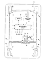
本実施例の車両挙動制御装置は、図1に示す電子制御装置(ECU)1の一機能として用意されたものとする。 The vehicle behavior control device of this embodiment is prepared as a function of the electronic control unit (ECU) 1 shown in FIG.
最初に、この車両挙動制御装置が適用される車両10の一例を図1に示す。
First, an example of a
この車両10には、エンジンやモータ等の動力源20が設けられている。この車両10は、その動力源20の動力を駆動輪に駆動力として伝達して走行する。そして、この車両10には、その走行中の車両10を停止又は減速させる制動システムが用意されている。その制動システムは、夫々の車輪WFL,WFR,WRL,WRRに対して個別の大きさで目標車輪制動トルク(目標車輪制動力)を発生させることができるよう構成されている。ここでは、ブレーキ液圧の力を利用して係合要素間に摩擦力を発生させ、これにより車輪WFL,WFR,WRL,WRRに目標車輪制動トルク(目標車輪制動力)を働かせるものについて例示する。
The
先ず、この制動システムは、図1及び図2に示す如く、運転者が操作するブレーキペダル31と、このブレーキペダル31に入力されたブレーキ操作に伴う操作圧力(ペダル踏力)を所定の倍力比で倍化させる制動倍力装置(ブレーキブースタ)32と、この制動倍力装置32により倍化されたペダル踏力をブレーキペダル31の操作量に応じたブレーキ液圧(以下、「マスタシリンダ圧」という。)へと変換するマスタシリンダ33と、ブレーキ液を貯留するリザーバタンク34と、を備えている。これらブレーキペダル31や制動倍力装置32等は、運転者によるブレーキペダル31の操作量に応じたブレーキ液圧を発生させる液圧発生装置として機能する。
First, as shown in FIGS. 1 and 2, this braking system includes a
また、この制動システムには、マスタシリンダ圧を各車輪WFL,WFR,WRL,WRR毎に調節可能な液圧調節装置(以下、「ブレーキアクチュエータ」という。)35と、このブレーキアクチュエータ35を経たブレーキ液圧(マスタシリンダ圧又はマスタシリンダ圧を調圧したブレーキ液圧)が伝えられる各車輪WFL,WFR,WRL,WRRの液圧配管36FL,36FR,36RL,36RRと、これら各液圧配管36FL,36FR,36RL,36RRのブレーキ液圧が各々供給されて夫々の車輪WFL,WFR,WRL,WRRに車輪制動トルク(車輪制動力)を発生させる制動装置(ディスクロータやキャリパ等で構成されたものやドラムやホイールシリンダ等で構成されたもの)37FL,37FR,37RL,37RRと、が設けられている。
The braking system includes a hydraulic pressure adjusting device (hereinafter referred to as “brake actuator”) 35 that can adjust the master cylinder pressure for each wheel W FL , W FR , W RL , W RR , and the brake actuator. The
本実施例のブレーキアクチュエータ35は、右前輪WFR及び左後輪WRLに対してブレーキ液圧を伝える第1液圧系統と、左前輪WFL及び右後輪WRRに対してブレーキ液圧を伝える第2液圧系統と、を備えたものとして例示する。つまり、このブレーキアクチュエータ35は、所謂X配管のブレーキ液圧回路を有する構造になっている。その第1液圧系統には、マスタシリンダ33の内部の一方の油圧室から第1液圧配管38を介してブレーキ液圧が供給される。一方、第2液圧系統には、マスタシリンダ33の内部の他方の油圧室から第2液圧配管39を介してブレーキ液圧が供給される。
The
このブレーキアクチュエータ35には、第1及び第2の液圧系統における夫々のブレーキ液の流量調節装置としてのマスタカット弁41,42を備えている。マスタカット弁41には第1液圧配管38が接続され、マスタカット弁42には第2液圧配管39が接続される。これら各マスタカット弁41,42は、通常は開弁状態にある所謂常開式の流量調整用電磁弁であって、電子制御装置1の指令による通電に伴って弁開度の制御を実行する。従って、夫々のマスタカット弁41,42は、通電量に応じて弁開度を制御することで、後述する加圧ポンプ69,70から吐出されたブレーキ液の圧力を調節してマスタシリンダ33側へ開放することができる。
The
このブレーキアクチュエータ35においては、第1液圧配管38がマスタカット弁41を介して連結通路43に接続されると共に、第2液圧配管39がマスタカット弁42を介して連結通路44に接続される。そして、第1液圧系統の連結通路43には、そこから分岐させるが如く2本の分岐通路45,46を接続し、第2液圧系統の連結通路44には、そこから分岐させるが如く2本の分岐通路47,48を接続する。第1液圧系統においては、その各々の分岐通路45,46を夫々に右前輪WFRの液圧配管36FRと左後輪WRLの液圧配管36RLに接続する。一方、第2液圧系統においては、その各々の分岐通路47,48を夫々に右後輪WRRの液圧配管36RRと左前輪WFLの液圧配管36FLに接続する。
In the
また、その各分岐通路45,46,47,48上には、夫々の制動装置37FR,37RL,37RR,37FL毎のブレーキ液圧を調整可能な液圧調圧部が車輪WFR,WRL,WRR,WFL毎に配設されている。その夫々の液圧調圧部は、車輪WFR,WRL,WRR,WFL毎に用意された保持弁50,51,52,53と液圧排出通路54,55,56,57と減圧弁58,59,60,61とで構成される。ここでは、各分岐通路45,46,47,48上に保持弁50,51,52,53が各々配備されており、更に、これら各保持弁50,51,52,53よりも下流側に液圧排出通路54,55,56,57が夫々に分岐通路45,46,47,48から分岐させるが如く接続されている。そして、その各液圧排出通路54,55,56,57上には、夫々に減圧弁58,59,60,61が配備されている。尚、ここで云う下流とは、ブレーキペダル操作時のブレーキ液の流動方向(つまり、制動装置37FL,37FR,37RL,37RRへと向かう方向)における下流側のことを表す。
Further, the on the
保持弁50,51,52,53は、所謂常開式の電磁弁であって、非励磁状態の通常時には開弁状態にあり、電子制御装置1の指令による通電に伴って励磁状態となり閉弁させられるものである。一方、減圧弁58,59,60,61は、所謂常閉式の電磁弁であって、非励磁状態の通常時には閉弁状態にあり、電子制御装置1の指令による通電に伴って励磁状態となり開弁させられるものである。
The holding
また、このブレーキアクチュエータ35には、第1液圧系統の夫々の液圧排出通路54,55を一纏めにする液圧排出集合通路62と、第2液圧系統の夫々の液圧排出通路56,57を一纏めにする液圧排出集合通路63と、が用意されており、その夫々の液圧排出集合通路62,63が各々補助リザーバ64,65に接続されている。
The
更に、第1液圧系統においては、連結通路43と各分岐通路45,46との分岐点から分岐して液圧排出集合通路62に接続されるポンプ通路66を配設する。これと同様に、第2液圧系統には、連結通路44と各分岐通路47,48との分岐点から分岐して液圧排出集合通路63に接続されるポンプ通路67を配設する。
Further, in the first hydraulic system, a
その夫々のポンプ通路66,67には、電動機(ここでは1つの電動機68)によって駆動される加圧ポンプ(加圧部)69,70を各々配備している。これら各加圧ポンプ69,70は、夫々にマスタカット弁41,42側の各分岐点に向けてブレーキ液を吐出させるものであり、夫々に分岐通路45,46と分岐通路47,48に対して加圧されたブレーキ液圧を供給する。つまり、第1液圧系統の加圧ポンプ69は、右前輪WFRと左後輪WRLに発生させる制動力を増大させるべく、夫々の制動装置37FR,37RLに供給するブレーキ液圧の増圧を行う。一方、第2液圧系統の加圧ポンプ70は、左前輪WFLと右後輪WRRに発生させる制動力を増大させるべく、夫々の制動装置37FL,37RRに供給するブレーキ液圧の増圧を行う。尚、電動機68は、図示しないバッテリからの電力供給により駆動する。また、その各ポンプ通路66,67には、加圧ポンプ69,70から吐出された夫々のブレーキ液の脈動を回避するダンパ室71,72が配設されている。
The
また、このブレーキアクチュエータ35には、第1及び第2の液圧配管38,39から各々分岐して補助リザーバ64,65に夫々接続される吸入通路73,74が配設されており、更に、その夫々の吸入通路73,74の補助リザーバ64,65側にリザーバカット逆止弁75,76が配設されている。
The
この制動システムには、制御対象輪の制動力を増加させる増圧モード、制御対象輪の制動力をそのときの大きさのまま保持する保持モード、制御対象輪の制動力を減少させる減圧モードがある。制御対象輪を増圧モード、保持モード又は減圧モードに制御する際、電子制御装置1は、その制御対象輪を含む液圧系統のマスタカット弁41,42を閉弁させる。
This braking system has a pressure increasing mode for increasing the braking force of the wheel to be controlled, a holding mode for maintaining the braking force of the wheel to be controlled as it is, and a pressure reducing mode for decreasing the braking force of the wheel to be controlled. is there. When controlling the wheel to be controlled in the pressure increasing mode, the holding mode or the pressure reducing mode, the electronic control unit 1 closes the master cut
制御対象輪が第1液圧系統に含まれているときには、マスタカット弁41を閉弁して、第1液圧配管38と保持弁50,51の上流の連結通路43とを遮断する。そして、例えば右前輪WFRが制御対象輪の場合、電子制御装置1は、増圧モードへと制御する際に、保持弁50が開弁状態で且つ減圧弁58が閉弁状態となるよう制御することで、右前輪WFRの制動装置37FRへのブレーキ液圧を増加させる。また、電子制御装置1は、保持モードへと制御する際に、保持弁50と減圧弁58が閉弁状態となるよう制御することで、右前輪WFRの制動装置37FRへのブレーキ液圧をそのときの大きさのまま保持させる。また、電子制御装置1は、減圧モードへと制御する際に、保持弁50が閉弁状態で且つ減圧弁58が開弁状態となるよう制御することで、右前輪WFRの制動装置37FRへのブレーキ液圧を減少させる。左後輪WRLについても、そのモードに応じて、保持弁51と減圧弁59を右前輪WFRのときと同じように制御する。
When the control target wheel is included in the first hydraulic system, the master cut
これと同様に、制御対象輪が第2液圧系統に含まれているときには、マスタカット弁42を閉弁して、第2液圧配管39と保持弁52,53の上流の連結通路44とを遮断する。そして、例えば左前輪WFLが制御対象輪の場合、電子制御装置1は、増圧モードへと制御する際に、保持弁53が開弁状態で且つ減圧弁61が閉弁状態となるよう制御することで、左前輪WFLの制動装置37FLへのブレーキ液圧を増加させる。また、電子制御装置1は、保持モードへと制御する際に、保持弁53と減圧弁61が閉弁状態となるよう制御することで、左前輪WFLの制動装置37FLへのブレーキ液圧をそのときの大きさのまま保持させる。また、電子制御装置1は、減圧モードへと制御する際に、保持弁53が閉弁状態で且つ減圧弁61が開弁状態となるよう制御することで、左前輪WFLの制動装置37FLへのブレーキ液圧を減少させる。右後輪WRRについても、そのモードに応じて、保持弁52と減圧弁60を左前輪WFLのときと同じように制御する。
Similarly, when the control target wheel is included in the second hydraulic system, the master cut
車両挙動制御装置は、旋回中の車両挙動の安定化制御を行う。その安定化制御とは、所謂ビークルスタビリティ制御のことである。車両10は、運転者のステアリングホイール81の操舵操作に伴う旋回動作の最中に、その挙動がニュートラルステア傾向を示すこともあれば、オーバーステア傾向やアンダーステア傾向を示すことがある。電子制御装置1は、車速、車両前後加速度や車両横加速度、ヨーレート等の車両走行情報に基づいて、車両10の挙動、つまり車体の実際の旋回状態(実旋回状態)を判断する。その判断の際には、その車両走行情報に基づいて、実旋回状態を示す車体のヨーモーメントが演算される。尚、車速は、例えば車輪WFL,WFR,WRL,WRRの車輪速度(車輪速度センサ91,92,93,94で検出)や図示しない変速機の出力軸の回転速度等から推定すればよい。また、車両前後加速度は、車両前後加速度センサ95に検出させ、車両横加速度は車両横加速度センサ96に検出させればよい。また、ヨーレートは、ヨーレートセンサ97に検出させればよい。
The vehicle behavior control device performs stabilization control of vehicle behavior during turning. The stabilization control is so-called vehicle stability control. The
車体の実旋回状態がオーバーステア傾向を示すときには、前後何れか又は双方の旋回外輪に車輪制動力を発生させることで、そのオーバーステア傾向を示すヨーモーメント(実旋回挙動量)とは逆向きのヨーモーメント(旋回制御量)を車体に作用させることができる。これが為、車体がオーバーステア傾向を示すときには、旋回外輪に発生させた車輪制動力によって、そのオーバーステア傾向を抑えることができる。これが為、車両10は、適切な大きさの旋回制御量を旋回外輪の車輪制動力によって発生させることで、過大なオーバーステア傾向となる実旋回状態を目標旋回状態に抑え、その目標旋回状態を保ったまま旋回動作を行うことができる。
When the actual turning state of the vehicle body shows an oversteer tendency, the wheel braking force is generated on one of the front and rear or both turning outer wheels to reverse the yaw moment (actual turning behavior amount) indicating the oversteer tendency. A yaw moment (a turning control amount) can be applied to the vehicle body. Therefore, when the vehicle body shows an oversteer tendency, the oversteer tendency can be suppressed by the wheel braking force generated in the turning outer wheel. For this reason, the
また、車体の実旋回状態がアンダーステア傾向を示すときには、前後何れか又は双方の旋回内輪に車輪制動力を発生させることで、そのアンダーステア傾向を示すヨーモーメント(実旋回挙動量)とは逆向きのヨーモーメント(旋回制御量)を車体に作用させることができる。これが為、車体がアンダーステア傾向を示すときには、旋回内輪に発生させた車輪制動力によって、そのアンダーステア傾向を抑えることができる。これが為、車両10は、適切な大きさの旋回制御量を旋回内輪の車輪制動力によって発生させることで、過大なアンダーステア傾向となる実旋回状態を目標旋回状態に抑え、その目標旋回状態を保ったまま旋回動作を行うことができる。
In addition, when the actual turning state of the vehicle body shows an understeer tendency, the wheel braking force is generated on one or both of the front and rear turning inner wheels to reverse the yaw moment (actual turning behavior amount) indicating the understeer tendency. A yaw moment (a turning control amount) can be applied to the vehicle body. For this reason, when the vehicle body shows an understeer tendency, the understeer tendency can be suppressed by the wheel braking force generated on the turning inner wheel. For this reason, the
その目標旋回状態とは、目標旋回挙動量(目標とする大きさのヨーモーメント)で旋回している状態のことであり、例えばニュートラルステア傾向や弱アンダーステア傾向を示す状態である。電子制御装置1は、車体の実旋回状態が何れの傾向であるのかに拘わらず、目標旋回状態の実現の為に発生させる逆向きの目標ヨーモーメント(目標旋回制御量)を演算する。その逆向きの目標ヨーモーメントは、実旋回状態と目標旋回状態との偏差、換言するならば実旋回挙動量と目標旋回挙動量との差に応じて決まる。 The target turning state is a state of turning with a target turning behavior amount (a yaw moment having a target magnitude), for example, a state showing a neutral steer tendency or a weak understeer tendency. The electronic control unit 1 calculates a reverse target yaw moment (target turning control amount) generated for realizing the target turning state regardless of the tendency of the actual turning state of the vehicle body. The target yaw moment in the opposite direction is determined according to the deviation between the actual turning state and the target turning state, in other words, the difference between the actual turning behavior amount and the target turning behavior amount.
ここで、この制動システムにおいては、マスタシリンダ圧の検出を行うマスタシリンダ圧センサが用意されていない。これが為、車両挙動制御装置は、マスタシリンダ圧の変化から運転者のブレーキ操作を把握することができない。そこで、この車両挙動制御装置は、車両挙動の安定化制御中に運転者がブレーキ操作を行った場合を考慮して、その安定化制御を行う際に、第1液圧系統又は第2液圧系統の内の一方のみを液圧制御対象とし、他の液圧系統を液圧制御が行われないように非液圧制御対象とする。従って、電子制御装置1は、その液圧制御対象となる液圧系統に属する制御対象輪の車輪制動力によって安定化制御を行う。その安定化制御を行う際には、液圧制御対象となる液圧系統のマスタカット弁41(42)を閉弁させると共に、非液圧制御対象となる液圧系統のマスタカット弁42(41)を開弁させたままにする。これにより、安定化制御中に運転者がブレーキ操作を行った場合には、そのブレーキ操作に応じたマスタシリンダ圧が非液圧制御対象となる液圧系統の車輪に供給されるので、この車輪の車輪制動力によってブレーキ操作に伴う制動力を車体に作用させることができる。 Here, in this braking system, a master cylinder pressure sensor for detecting the master cylinder pressure is not prepared. For this reason, the vehicle behavior control device cannot grasp the driver's brake operation from the change in the master cylinder pressure. Therefore, this vehicle behavior control device takes into account the case where the driver performs a brake operation during the vehicle behavior stabilization control, and when performing the stabilization control, the first hydraulic system or the second hydraulic pressure. Only one of the systems is set as a hydraulic control target, and the other hydraulic system is set as a non-hydraulic control target so that hydraulic control is not performed. Therefore, the electronic control unit 1 performs the stabilization control by the wheel braking force of the control target wheel belonging to the hydraulic system that is the hydraulic pressure control target. When performing the stabilization control, the master cut valve 41 (42) of the hydraulic system to be hydraulically controlled is closed, and the master cut valve 42 (41 of the hydraulic system to be non-hydraulic controlled) is used. ) Is left open. As a result, when the driver performs a brake operation during the stabilization control, the master cylinder pressure corresponding to the brake operation is supplied to the wheel of the hydraulic system that is the target of non-hydraulic control. The braking force accompanying the brake operation can be applied to the vehicle body by the wheel braking force.
ところで、車体は、実旋回挙動量が大きくなるほど、オーバーステア傾向又はアンダーステア傾向が強くなる。これが為、目標旋回状態を実現させる為には、実旋回挙動量が大きくなるほど、目標旋回制御量を大きくする必要がある。そして、その目標旋回制御量を大きくする為には、目標旋回制御量が大きいほど、制御対象輪の車輪制動力を大きくする必要がある。しかしながら、制動システム上、車輪制動力には、発生可能な上限がある。これが為、制御対象輪を一方の液圧系統に属するものだけに限定してしまうと、実旋回挙動量(換言するならば目標旋回制御量)が所定量を超えている場合には、その一方の液圧系統の制御対象輪の車輪制動力だけで目標旋回制御量を発生させることができず、安定化制御の目標旋回状態への制御性能を低下させてしまう可能性がある。 By the way, as the actual turning behavior amount increases, the oversteer tendency or the understeer tendency becomes stronger. Therefore, in order to realize the target turning state, it is necessary to increase the target turning control amount as the actual turning behavior amount increases. In order to increase the target turning control amount, it is necessary to increase the wheel braking force of the wheel to be controlled as the target turning control amount increases. However, on the braking system, the wheel braking force has an upper limit that can be generated. For this reason, if the wheels to be controlled are limited to those belonging to one hydraulic system, if the actual turning behavior amount (in other words, the target turning control amount) exceeds a predetermined amount, The target turning control amount cannot be generated only by the wheel braking force of the wheel to be controlled in the hydraulic system, and the control performance of the stabilization control to the target turning state may be lowered.
ここで、非液圧制御対象になっている他方の液圧系統を観てみると、この液圧系統には、一方の液圧系統の制御対象輪と共に安定化制御の制御対象輪となり得る車輪が属している。例えば、オーバーステア傾向を示すときには、一方の液圧系統の前側の旋回外輪を制御対象輪としていれば、他方の液圧系統の後側の旋回外輪についても制御対象輪にすることができる。また、アンダーステア傾向を示すときには、一方の液圧系統の後側の旋回内輪を制御対象輪としていれば、他方の液圧系統の前側の旋回内輪についても制御対象輪にすることができる。 Here, looking at the other hydraulic system that is subject to non-hydraulic control, this hydraulic system includes wheels that can be controlled wheels for stabilization control together with the controlled wheels of one hydraulic system. Belongs to. For example, when an oversteer tendency is indicated, if the outer turning wheel on the front side of one hydraulic system is set as the control target wheel, the outer turning wheel on the rear side of the other hydraulic system can also be set as the control target wheel. Further, when an understeer tendency is exhibited, if the turning inner wheel on the rear side of one hydraulic system is set as the control target wheel, the turning inner wheel on the front side of the other hydraulic system can also be set as the control target wheel.
そこで、この車両挙動制御装置は、実旋回挙動量が所定量以下の場合又は目標旋回制御量の絶対値が所定量以下の場合、一方の液圧系統を液圧制御対象にすると共に、他方の液圧系統を非液圧制御対象にして、その一方の液圧系統の制御対象輪に車輪制動力を発生させることで、車両挙動の安定化制御を行う。これに対して、この車両挙動制御装置は、実旋回挙動量が所定量を超える場合又は目標旋回制御量の絶対値が所定量を超える場合、双方の液圧系統を液圧制御対象にし、夫々の液圧系統の制御対象輪に車輪制動力を発生させることで、車両挙動の安定化制御を行う。 Therefore, when the actual turning behavior amount is equal to or smaller than the predetermined amount or the absolute value of the target turning control amount is equal to or smaller than the predetermined amount, the vehicle behavior control device sets one hydraulic system as a hydraulic control target and Stabilization control of the vehicle behavior is performed by setting the hydraulic system as a non-hydraulic control target and generating wheel braking force on the control target wheel of one of the hydraulic systems. On the other hand, when the actual turning behavior amount exceeds a predetermined amount or when the absolute value of the target turning control amount exceeds a predetermined amount, this vehicle behavior control device makes both hydraulic systems subject to hydraulic pressure control, respectively. The vehicle behavior stabilization control is performed by generating wheel braking force on the control target wheel of the hydraulic system.
その所定量とは、例えば、1つの車輪において発生可能な車輪制動力の上限値又は当該上限値に対して油路やブレーキ液の粘度等による誤差分などを考慮に入れた補正値で決まる。具体的には、その上限値又は補正値の車輪制動力を1つの制御対象輪で発生させ、その際に車体に発生する旋回制御量(逆方向のモーメント)によって決まる。例えば、時計回りのモーメントを正とする。この場合、実旋回挙動量に対する所定量は、目標旋回挙動量に対して、その上限値又は補正値の車輪制動力によって発生する旋回制御量(逆方向のモーメント)を減算した値になる。また、目標旋回制御量に対する所定量は、その上限値又は補正値の車輪制動力によって発生する旋回制御量(逆方向のモーメント)の絶対値になる。 The predetermined amount is determined by, for example, an upper limit value of the wheel braking force that can be generated in one wheel or a correction value that takes into account the error due to the viscosity of the oil passage or brake fluid with respect to the upper limit value. Specifically, the wheel braking force of the upper limit value or the correction value is generated by one wheel to be controlled, and is determined by the turning control amount (moment in the reverse direction) generated in the vehicle body at that time. For example, a clockwise moment is positive. In this case, the predetermined amount for the actual turning behavior amount is a value obtained by subtracting the turning control amount (moment in the reverse direction) generated by the wheel braking force of the upper limit value or the correction value from the target turning behavior amount. The predetermined amount for the target turning control amount is an absolute value of the turning control amount (moment in the reverse direction) generated by the wheel braking force of the upper limit value or the correction value.
ここで、双方の液圧系統を液圧制御対象にした場合には、両方のマスタカット弁41,42が閉弁しているので、運転者がブレーキ操作を行っても、マスタシリンダ圧が何れの車輪WFL,WFR,WRL,WRRに対しても伝わらない。これが為、この場合の安定化制御中に運転者がブレーキ操作を行ったときには、液圧制御対象になっている2つの液圧系統の内の一方の液圧制御量を現状の目標液圧制御量よりも増加させる。
Here, when both hydraulic systems are controlled by hydraulic pressure, both master cut
以下、図3のフローチャートを用いて具体的に説明する。 This will be specifically described below with reference to the flowchart of FIG.
先ず、電子制御装置1は、ヨーレート等の車両走行情報に基づいて、車体が車両挙動の安定化制御の実行を要するアンダーステア(US)の状態又はオーバーステア(OS)の状態であるのか否かを判定する(ステップST1)。このステップST1の判定は、常時実行してもよいが、例えば操舵角度センサ82の検出信号(ステアリングホイール81の操舵角度)に基づいた運転者の操舵操作の検知を契機にして実行してもよい。 First, the electronic control unit 1 determines whether the vehicle body is in an understeer (US) state or an oversteer (OS) state that requires execution of vehicle behavior stabilization control based on vehicle travel information such as the yaw rate. Determine (step ST1). The determination in step ST1 may be performed constantly, but may be performed in response to detection of the driver's steering operation based on a detection signal from the steering angle sensor 82 (steering angle of the steering wheel 81), for example. .
電子制御装置1は、車体の実旋回状態が過大なアンダーステア傾向又は過大なオーバーステア傾向を示していなければ、例えば目標旋回状態になっていれば、このステップST1で否定判定を行う。この場合には、このステップST1の判定を繰り返す。 If the actual turning state of the vehicle body does not indicate an excessive understeer tendency or an excessive oversteer tendency, for example, if the electronic control apparatus 1 is in a target turning state, the electronic control device 1 makes a negative determination in step ST1. In this case, the determination in step ST1 is repeated.
一方、この電子制御装置1は、車体の実旋回状態が過大なアンダーステア傾向又は過大なオーバーステア傾向を示していれば、このステップST1で肯定判定を行う。この場合、電子制御装置1は、アンダーステアの状態又はオーバーステアの状態が1つの液圧系統での安定化制御の実行可能な限界を超えているのか否かを判定する(ステップST2)。ここでは、実旋回挙動量が上記の所定量を超えているのか否か又は目標旋回制御量の絶対値が上記の所定量を超えているのか否かを判定する。尚、その実旋回挙動量としては、ステップST1の判定の際に求めたヨーモーメントを用いればよい。また、目標旋回制御量は、その実旋回挙動量と目標旋回挙動量の差から求める。 On the other hand, if the actual turning state of the vehicle body shows an excessive understeer tendency or an excessive oversteer tendency, the electronic control unit 1 makes an affirmative determination in step ST1. In this case, the electronic control unit 1 determines whether or not the understeer state or the oversteer state exceeds a feasible limit of the stabilization control in one hydraulic system (step ST2). Here, it is determined whether the actual turning behavior amount exceeds the predetermined amount or whether the absolute value of the target turning control amount exceeds the predetermined amount. As the actual turning behavior amount, the yaw moment obtained at the time of determination in step ST1 may be used. Further, the target turning control amount is obtained from the difference between the actual turning behavior amount and the target turning behavior amount.
このステップST2においては、実旋回挙動量が所定量以下の場合又は目標旋回制御量の絶対値が所定量以下の場合に否定判定を行う。この場合には、一方の液圧系統(第1液圧系統又は第2液圧系統の内の何れか一方)に属している制御対象輪の車輪制動力だけで目標旋回制御量を発生させることが可能なので、その車輪制動力で車体を目標旋回状態にすることができる。これが為、電子制御装置1は、一方の液圧系統を液圧制御対象にすると共に、他方の液圧系統を非液圧制御対象にし、その液圧制御対象とする一方の液圧系統の制御対象輪の車輪制動力によって安定化制御を実行する(ステップST3)。 In step ST2, a negative determination is made when the actual turning behavior amount is equal to or smaller than a predetermined amount or when the absolute value of the target turning control amount is equal to or smaller than the predetermined amount. In this case, the target turning control amount is generated only by the wheel braking force of the wheel to be controlled belonging to one hydraulic system (one of the first hydraulic system or the second hydraulic system). Therefore, the vehicle body can be brought into the target turning state with the wheel braking force. For this reason, the electronic control unit 1 sets one hydraulic system as a hydraulic control target, and sets the other hydraulic system as a non-hydraulic control target, and controls one hydraulic system as the hydraulic control target. Stabilization control is executed by the wheel braking force of the target wheel (step ST3).
例えば、この場合には、右旋回時にアンダーステア傾向を示していれば、制御対象輪である右後輪WRRの属する第2液圧系統を液圧制御対象にし、左旋回時にアンダーステア傾向を示していれば、制御対象輪である左後輪WRLの属する第1液圧系統を液圧制御対象にする。また、この場合には、右旋回時にオーバーステア傾向を示していれば、制御対象輪である左前輪WFLの属する第2液圧系統を液圧制御対象にし、左旋回時にオーバーステア傾向を示していれば、制御対象輪である右前輪WFRの属する第1液圧系統を液圧制御対象にする。 For example, in this case, if an understeering tendency is shown during a right turn, the second hydraulic system to which the right rear wheel WRR , which is a wheel to be controlled, belongs is set as a hydraulic control target, and an understeering tendency is shown during a left turn. If so, the first hydraulic system to which the left rear wheel WRL , which is the control target wheel, belongs is set as the hydraulic control target. Also, in this case, if an oversteer tendency is shown during a right turn, the second hydraulic system to which the front left wheel WFL , which is the control target wheel, belongs is set as a hydraulic control target, and an oversteer tendency is shown during a left turn. if indicated, the first hydraulic system Field of the right front wheel W FR is controlled wheel liquid pressure control target.
電子制御装置1は、そのときの実旋回挙動量と目標旋回挙動量に基づいて目標旋回制御量を求め、その目標旋回制御量を車体に発生させることが可能な制御対象輪の目標車輪制動力を求める。そして、電子制御装置1は、その目標車輪制動力を制御対象輪に発生させるようブレーキアクチュエータ35を制御する。その際には、液圧制御対象となる液圧系統の車輪の内、制御対象輪を増圧モードに制御し、残りの車輪を保持モードに制御する。これにより、車両10は、アンダーステア傾向又はオーバーステア傾向が抑制され、目標旋回状態で旋回することができる。
The electronic control unit 1 obtains the target turning control amount based on the actual turning behavior amount and the target turning behavior amount at that time, and the target wheel braking force of the control target wheel that can generate the target turning control amount in the vehicle body. Ask for. Then, the electronic control unit 1 controls the
ここで、この安定化制御中に運転者がブレーキ操作を行った場合、車両10においては、非液圧制御対象になっている液圧系統のマスタカット弁41(42)が開弁しているので、この液圧系統に属する夫々の車輪にマスタシリンダ圧が供給され、この車輪にブレーキ操作に応じた車輪制動力が発生する。従って、この車両挙動制御装置は、車両挙動の安定化を図りつつ、その最中のブレーキ操作に対応させた制動力を発生させることができる。
Here, when the driver performs a brake operation during the stabilization control, in the
運転者がブレーキ操作を止めたときには、非液圧制御対象の液圧系統の車輪へのマスタシリンダ圧の供給が終わる。電子制御装置1は、ステップST3の安定化制御の実行の後、ステップST1に戻って演算処理を繰り返しているので、ブレーキ操作を止めた後も安定化制御が必要と判断されれば、今現在実行中の1つの液圧系統での安定化制御又は下記の両方の液圧系統での安定化制御を実行する。 When the driver stops the brake operation, the supply of the master cylinder pressure to the wheels of the hydraulic system subject to non-hydraulic control ends. After executing the stabilization control in step ST3, the electronic control unit 1 returns to step ST1 and repeats the arithmetic processing. Therefore, if it is determined that the stabilization control is necessary even after the brake operation is stopped, Stabilization control in one hydraulic system being executed or stabilization control in both of the following hydraulic systems is executed.
また、上記のステップST2においては、実旋回挙動量が所定量を超える場合又は目標旋回制御量の絶対値が所定量を超える場合に肯定判定を行う。この場合には、一方の液圧系統(第1液圧系統又は第2液圧系統の内の何れか一方)に属している制御対象輪の車輪制動力だけでは、その車輪制動力により車体に発生する旋回制御量が目標旋回制御量に対して不足しており、車体を目標旋回状態に至らせることができない。これが為、電子制御装置1は、第1液圧系統と第2液圧系統の両方を液圧制御対象にし、この第1及び第2の液圧系統に各々属している制御対象輪の車輪制動力によって安定化制御を実行する(ステップST4)。 In step ST2, an affirmative determination is made when the actual turning behavior amount exceeds a predetermined amount or when the absolute value of the target turning control amount exceeds a predetermined amount. In this case, only the wheel braking force of the wheel to be controlled belonging to one hydraulic system (either the first hydraulic system or the second hydraulic system) is applied to the vehicle body by the wheel braking force. The generated turning control amount is insufficient with respect to the target turning control amount, and the vehicle body cannot be brought into the target turning state. For this reason, the electronic control unit 1 sets both the first hydraulic system and the second hydraulic system as hydraulic control targets, and controls the wheel control target wheels belonging to the first and second hydraulic systems, respectively. Stabilization control is executed by power (step ST4).
例えば、この場合には、右旋回時にアンダーステア傾向を示していれば、制御対象輪である右前輪WFRの属する第1液圧系統と同じく制御対象輪である右後輪WRRの属する第2液圧系統とを液圧制御対象にし、左旋回時にアンダーステア傾向を示していれば、制御対象輪である左後輪WRLの属する第1液圧系統と同じく制御対象輪である左前輪WFLの属する第2液圧系統とを液圧制御対象にする。また、この場合には、右旋回時にオーバーステア傾向を示していれば、制御対象輪である左後輪WRLの属する第1液圧系統と同じく制御対象輪である左前輪WFLの属する第2液圧系統とを液圧制御対象にし、左旋回時にオーバーステア傾向を示していれば、制御対象輪である右前輪WFRの属する第1液圧系統と同じく制御対象輪である右後輪WRRの属する第2液圧系統とを液圧制御対象にする。 For example, in this case, if shows the understeer tendency during the right turn, the belongs is likewise controlled wheel and the first hydraulic system Field of the right front wheel W FR is controlled wheel right rear wheel W RR If the two-hydraulic pressure system is subject to hydraulic control and shows an understeer tendency when turning left, the left front wheel W, which is the control target wheel, is the same as the first hydraulic system to which the left rear wheel WRL , which is the control target wheel, belongs. The second hydraulic system to which the FL belongs is set as a hydraulic control target. Further, in this case, if an oversteer tendency is shown when turning right, the left front wheel WFL , which is the control target wheel, belongs to the first hydraulic system to which the left rear wheel WRL , which is the control target wheel, belongs. a second hydraulic system in the hydraulic control object, if shows the oversteer tendency during turning left, right rear is likewise controlled wheel and the first hydraulic system Field of the right front wheel W FR is controlled wheel The second hydraulic system to which the wheel WRR belongs is set as a hydraulic control target.
電子制御装置1は、この場合にも、そのときの実旋回挙動量と目標旋回挙動量に基づいて目標旋回制御量を求める。そして、この電子制御装置1は、その目標旋回制御量を車体に発生させることが可能な夫々の制御対象輪の目標車輪制動力を求め、その目標車輪制動力を夫々の制御対象輪に発生させるようブレーキアクチュエータ35を制御する。その際、夫々の制御対象輪の目標車輪制動力は、夫々の制御対象輪で均等の大きさに設定してもよく、前後で大きさを変えてもよい。例えば、後者の例としては、一方の液圧系統で安定化制御を行うときの制御対象輪の車輪制動力を上述した上限値又は補正値まで発生させ、目標旋回制御量に対する不足分の車輪制動力を他方の液圧系統に属する制御対象輪に発生させる。その際には、夫々の液圧系統の車輪の内、制御対象輪を増圧モードに制御し、残りの車輪を保持モードに制御する。このように、車両10は、両方の液圧系統で安定化制御を行うことによって、アンダーステア傾向又はオーバーステア傾向が抑制され、目標旋回状態で旋回することができる。
Also in this case, the electronic control unit 1 obtains the target turning control amount based on the actual turning behavior amount and the target turning behavior amount at that time. The electronic control unit 1 obtains the target wheel braking force of each control target wheel that can generate the target turning control amount on the vehicle body, and generates the target wheel braking force on each control target wheel. The
ここで、この安定化制御中に運転者がブレーキ操作を行った場合、この車両10においては、両方の液圧系統のマスタカット弁41,42が閉弁しているので、ブレーキ操作に伴うマスタシリンダ圧をどの車輪にも供給できない。これが為、この場合、電子制御装置1は、先ず、運転者がブレーキ操作を行ったのか否かについて、ストップスイッチ98がオン信号を出力しているのか否かを観て判断する(ステップST5)。そのストップスイッチ98とは、車両後端のストップランプ(図示略)を点灯させる際のスイッチのことであり、運転者のブレーキ操作に連動してオン信号を出力する。
Here, when the driver performs a brake operation during the stabilization control, the master cut
電子制御装置1は、ストップスイッチ98のオン信号が検知されず、これ以降も安定化制御が必要と判断されれば、実旋回挙動量又は目標旋回制御量の大きさに応じて、そのまま2つの液圧系統による安定化制御を続ける又は1つの液圧系統による安定化制御に切り替える。
If the ON signal of the
これに対して、電子制御装置1は、ストップスイッチ98のオン信号を検知したときに、運転者がブレーキ操作を行ったと判断し、両方の液圧系統の内の一方の液圧制御量(ブレーキ液圧)を増加させる(ステップST6)。これにより、その増加対象の液圧系統に属する車輪の車輪制動力が実行中の安定化制御時よりも増加するので、この車両挙動制御装置は、車両挙動の安定化を図りつつ、その最中のブレーキ操作に伴い制動力を発生させることができる。
On the other hand, when the electronic control unit 1 detects the ON signal of the
ここで、その増加の対象とする液圧系統は、2つの液圧系統の内、どちらに設定してもよい。例えば、上記の不足分の車輪制動力を発生させる制御対象輪が属する液圧系統をブレーキ液圧の増加の対象とする。これにより、逆の液圧系統をブレーキ液圧の増加の対象にするよりも、ブレーキ液圧の増加代を大きく取ることができる。 Here, the hydraulic system to be increased may be set to any of the two hydraulic systems. For example, the hydraulic pressure system to which the wheel to be controlled that generates the insufficient wheel braking force described above belongs is the target of the increase in the brake hydraulic pressure. As a result, the brake fluid pressure can be increased more than when the reverse hydraulic system is the target of the brake fluid pressure increase.
このステップST6では、増加の対象となる液圧系統において、制御対象輪の安定化制御の為の目標液圧制御量(目標ブレーキ液圧)よりも液圧制御量(ブレーキ液圧)を増加させる。また、ブレーキ液圧を増加させる車輪は、その制御対象輪だけでもよいが、車両挙動の安定性を考慮して、安定化制御の際に保持モードになっている車輪も含めて増加の対象にすることが好ましい。これが為、このステップST6においては、その車輪が保持モードから増圧モードに制御される。また、このステップST6においては、運転者のブレーキ操作によるペダル踏力が判らないので、車輪制動力を上記の上限値又は補正値まで増加させるようにブレーキ液圧を増加させてもよい。 In step ST6, in the hydraulic system to be increased, the hydraulic pressure control amount (brake hydraulic pressure) is increased more than the target hydraulic pressure control amount (target brake hydraulic pressure) for stabilizing control of the wheel to be controlled. . In addition, the wheel to increase the brake fluid pressure may be only the wheel to be controlled, but considering the stability of the vehicle behavior, the wheel including the wheel that is in the holding mode at the time of stabilization control is also subject to increase. It is preferable to do. For this reason, in step ST6, the wheel is controlled from the holding mode to the pressure increasing mode. In step ST6, since the pedal depression force by the driver's brake operation is not known, the brake fluid pressure may be increased so as to increase the wheel braking force to the above upper limit value or the correction value.
電子制御装置1は、ストップスイッチ98からのオン信号が検出されなくなったのか否か、つまりストップスイッチ98がオフになったのか否かを判定する(ステップST7)。
The electronic control unit 1 determines whether or not the on signal from the
ここで、オン信号が検出され続けている場合、電子制御装置1は、実行中のブレーキ液圧の増加を継続させる。 Here, when the ON signal is continuously detected, the electronic control unit 1 continues to increase the brake fluid pressure being executed.
一方、オン信号が検出されなくなった場合、電子制御装置1は、ステップST6で増加させたブレーキ液圧を増加分だけ減少させ(ステップST8)、ステップST1に戻る。その際には、増圧モードに切り替えた安定化制御とは無関係の車輪を減圧モード、保持モードの順に切り替える。これにより、電子制御装置1は、これ以降も安定化制御が必要と判断されたときに、実旋回挙動量又は目標旋回制御量の大きさに応じて、そのまま2つの液圧系統による安定化制御を続ける又は1つの液圧系統による安定化制御に切り替える。 On the other hand, when the ON signal is no longer detected, the electronic control unit 1 decreases the brake fluid pressure increased in step ST6 by the increment (step ST8), and returns to step ST1. In that case, the wheel unrelated to the stabilization control switched to the pressure increasing mode is switched in the order of the pressure reducing mode and the holding mode. As a result, when it is determined that the stabilization control is necessary thereafter, the electronic control unit 1 directly performs the stabilization control by the two hydraulic systems according to the actual turning behavior amount or the target turning control amount. Or switch to stabilization control by one hydraulic system.
以上示したように、この車両挙動制御装置は、制動システムがマスタシリンダ圧センサを具備していなくても、車両の挙動がアンダーステア傾向又はオーバーステア傾向を示した際に、大小様々なアンダーステア傾向又はオーバーステア傾向に適した目標旋回制御量(逆方向のヨーモーメント)を車体に作用させることができ、目標旋回状態への安定化制御を実現できる。更に、この車両挙動制御装置は、運転者がブレーキ操作を行ったときに、実行中の安定化制御が1つの液圧系統で行われていれば、他方の液圧系統でマスタシリンダ圧を供給して、ブレーキ操作に応じた制動力を車体に発生させることができる。また更に、この車両挙動制御装置は、そのブレーキ操作時の安定化制御が両方の液圧系統で行われていれば、その内の一方の液圧系統のブレーキ液圧を増加させることで、ブレーキ操作に伴う制動力を車体に発生させることができる。 As described above, this vehicle behavior control device can be used for various understeering trends of various magnitudes when the vehicle behavior shows an understeering tendency or an oversteering tendency even if the braking system does not include a master cylinder pressure sensor. A target turning control amount (a yaw moment in the reverse direction) suitable for the oversteer tendency can be applied to the vehicle body, and stabilization control to the target turning state can be realized. Further, this vehicle behavior control device supplies the master cylinder pressure with the other hydraulic system if the stabilization control being performed is performed with one hydraulic system when the driver performs a brake operation. Thus, a braking force corresponding to the brake operation can be generated in the vehicle body. Furthermore, this vehicle behavior control device increases the brake hydraulic pressure of one of the hydraulic systems when the stabilization control during the brake operation is performed in both hydraulic systems, thereby The braking force accompanying the operation can be generated in the vehicle body.
ところで、この例示ではブレーキ操作が終わってからステップST1に戻るようにしたが、例えば、上記の不足分の車輪制動力を発生させる制御対象輪が属している液圧系統をステップST6のブレーキ液圧の増加対象にする場合には、ブレーキ操作中の状態のままステップST1に戻してもよい。そして、そのステップST6においては、運転者のブレーキ操作に伴い発生するマスタシリンダ圧に基づいて、そのマスタシリンダ圧の平均値や上限値にブレーキ液圧を設定することが好ましい。これにより、後のステップST3で一方の液圧系統だけでの安定化制御が選択された際に、ブレーキ操作に伴う車輪制動力の変化を抑えることができるからである。つまり、その際には、ブレーキ液圧の増加対象になっている液圧系統が非液圧制御対象に切り替わり、この液圧系統のマスタカット弁41(42)が開弁するので、この液圧系統の車輪にブレーキ操作に応じたマスタシリンダ圧が供給される。ここで、ステップST6のブレーキ液圧をマスタシリンダ圧の平均値や上限値に設定していれば、マスタカット弁41(42)が開弁されたときのブレーキ液圧の変動を抑えることができ、ブレーキ操作に伴う車輪制動力の変化を抑えることができる。尚、マスタシリンダ圧の平均値は、これまでのブレーキ操作時に車輪速変化等から推定したマスタシリンダ圧の推定値に基づいた学習値として得ることができる。また、マスタシリンダ圧の上限値は、制動システムの諸元から予め把握できる。 By the way, in this example, after returning to step ST1 after the brake operation is finished, for example, the hydraulic system to which the wheel to be controlled that generates the insufficient wheel braking force belongs is set as the brake hydraulic pressure in step ST6. If the target is to be increased, it may be returned to step ST1 while the brake is being operated. In step ST6, it is preferable to set the brake fluid pressure to the average value or the upper limit value of the master cylinder pressure based on the master cylinder pressure generated with the driver's braking operation. Thereby, when stabilization control with only one hydraulic system is selected in the subsequent step ST3, it is possible to suppress a change in the wheel braking force accompanying the brake operation. That is, in this case, the hydraulic system that is the target of the increase in brake hydraulic pressure is switched to the non-hydraulic control target, and the master cut valve 41 (42) of this hydraulic system is opened. The master cylinder pressure corresponding to the brake operation is supplied to the wheels of the system. Here, if the brake fluid pressure in step ST6 is set to the average value or the upper limit value of the master cylinder pressure, fluctuations in the brake fluid pressure when the master cut valve 41 (42) is opened can be suppressed. The change of the wheel braking force accompanying the brake operation can be suppressed. The average value of the master cylinder pressure can be obtained as a learning value based on the estimated value of the master cylinder pressure estimated from the wheel speed change or the like during the previous braking operation. Further, the upper limit value of the master cylinder pressure can be grasped in advance from the specifications of the braking system.
また、この実施例においては、マスタシリンダ圧センサが設けられていない制動システムを例に挙げた。しかしながら、この車両挙動制御装置は、第1又は第2の液圧配管38,39の内の何れか一方にマスタシリンダ圧センサが配設された車両10についても上記の如き制御の対象にしてもよい。これにより、例えば、経年変化等によりマスタシリンダ圧センサの検出精度が落ちた場合でも、この車両挙動制御装置は、その検出結果に拘わらず上述したものと同様の効果を得ることができる。
In this embodiment, a braking system not provided with a master cylinder pressure sensor is taken as an example. However, this vehicle behavior control device also makes the above-described control target for the
以上のように、本発明に係る車両挙動制御装置は、車両挙動の安定化制御の制御性能を向上させる技術に有用である。 As described above, the vehicle behavior control device according to the present invention is useful for a technique for improving the control performance of the vehicle behavior stabilization control.
1 電子制御装置
10 車両
31 ブレーキペダル
33 マスタシリンダ
35 ブレーキアクチュエータ
37FL,37FR,37RL,37RR 制動装置
41,42 マスタカット弁
50,51,52,53 保持弁
58,59,60,61 減圧弁
81 ステアリングホイール
82 操舵角度センサ
91,92,93,94 車輪速度センサ
95 車両前後加速度センサ
96 車両横加速度センサ
97 ヨーレートセンサ
98 ストップスイッチ
WFL,WFR,WRL,WRR 車輪
1
Claims (2)
車体の実旋回挙動量が所定量を超える場合又は目標旋回制御量の絶対値が所定量を超える場合、前記両方の液圧系統を液圧制御対象に設定し、該夫々の液圧系統に属する夫々の制御対象輪の車輪制動力で前記安定化制御を行うことを特徴とした車両挙動制御装置。 When performing stabilization control of vehicle behavior by generating a target turning control amount corresponding to the deviation between the actual turning state and the target turning state of the vehicle by the wheel braking force of a predetermined wheel to be controlled, the two brake hydraulic pressures Among the hydraulic systems, the one to which the control target wheel belongs is set as a hydraulic control target, the master cut valve of the hydraulic system is closed, and the other hydraulic system is set as a non-hydraulic control target. A vehicle behavior control device that opens the master cut valve of the hydraulic system and adjusts the brake hydraulic pressure of the hydraulic system to be hydraulically controlled to generate the wheel braking force on the wheel to be controlled. And
When the actual turning behavior amount of the vehicle body exceeds a predetermined amount, or when the absolute value of the target turning control amount exceeds a predetermined amount, both the hydraulic systems are set as hydraulic pressure control targets and belong to the respective hydraulic systems. A vehicle behavior control device characterized in that the stabilization control is performed by a wheel braking force of each wheel to be controlled.
Priority Applications (1)
| Application Number | Priority Date | Filing Date | Title |
|---|---|---|---|
| JP2011003018A JP2012144117A (en) | 2011-01-11 | 2011-01-11 | Vehicle behavior control system |
Applications Claiming Priority (1)
| Application Number | Priority Date | Filing Date | Title |
|---|---|---|---|
| JP2011003018A JP2012144117A (en) | 2011-01-11 | 2011-01-11 | Vehicle behavior control system |
Publications (1)
| Publication Number | Publication Date |
|---|---|
| JP2012144117A true JP2012144117A (en) | 2012-08-02 |
Family
ID=46788168
Family Applications (1)
| Application Number | Title | Priority Date | Filing Date |
|---|---|---|---|
| JP2011003018A Withdrawn JP2012144117A (en) | 2011-01-11 | 2011-01-11 | Vehicle behavior control system |
Country Status (1)
| Country | Link |
|---|---|
| JP (1) | JP2012144117A (en) |
-
2011
- 2011-01-11 JP JP2011003018A patent/JP2012144117A/en not_active Withdrawn
Similar Documents
| Publication | Publication Date | Title |
|---|---|---|
| JP5800437B2 (en) | Method and apparatus for adjusting an electrohydraulic brake system of a motor vehicle | |
| CN102245448B (en) | brake control device | |
| US8924116B2 (en) | Motion control apparatus for vehicle | |
| CN102753408A (en) | Behavior Control Devices for Vehicles | |
| JP4636262B2 (en) | Vehicle center-of-gravity position lateral acceleration acquisition device and vehicle motion control device | |
| JP5295750B2 (en) | Control device for brake device | |
| JP4526342B2 (en) | 4-wheel drive vehicle motion control device | |
| WO2013191292A1 (en) | Vehicle braking force control apparatus | |
| JPH1059149A (en) | Braking force control device | |
| WO2018079696A1 (en) | Brake device for vehicle | |
| US8224546B2 (en) | ABS control system | |
| US7516008B2 (en) | Vehicle motion control apparatus | |
| WO2021060279A1 (en) | Brake device for vehicle | |
| JP5103917B2 (en) | Vehicle motion control device | |
| JP2002067917A (en) | Vehicle braking control device | |
| WO2015194351A1 (en) | Brake device | |
| JP2010006234A (en) | Vehicle control device | |
| JP5446685B2 (en) | Vehicle motion control device | |
| JP2012144117A (en) | Vehicle behavior control system | |
| JP5119009B2 (en) | Vehicle control device | |
| JP5071031B2 (en) | Braking control device | |
| JP5044583B2 (en) | Brake control device | |
| JP5729046B2 (en) | Braking force control device | |
| JP5966994B2 (en) | Brake control device for vehicle | |
| JP2013060117A (en) | Vehicle behavior control system |
Legal Events
| Date | Code | Title | Description |
|---|---|---|---|
| A300 | Withdrawal of application because of no request for examination |
Free format text: JAPANESE INTERMEDIATE CODE: A300 Effective date: 20140401 |