JP2012143533A - Body temperature regulation pack and pack holder for attaching the body temperature regulation pack - Google Patents

Body temperature regulation pack and pack holder for attaching the body temperature regulation pack Download PDF

Info

Publication number
JP2012143533A
JP2012143533A JP2011132056A JP2011132056A JP2012143533A JP 2012143533 A JP2012143533 A JP 2012143533A JP 2011132056 A JP2011132056 A JP 2011132056A JP 2011132056 A JP2011132056 A JP 2011132056A JP 2012143533 A JP2012143533 A JP 2012143533A
Authority
JP
Japan
Prior art keywords
pack
body temperature
temperature regulation
solid
liquid phase
Prior art date
Legal status (The legal status is an assumption and is not a legal conclusion. Google has not performed a legal analysis and makes no representation as to the accuracy of the status listed.)
Pending
Application number
JP2011132056A
Other languages
Japanese (ja)
Inventor
Takashi Hasegawa
高士 長谷川
Current Assignee (The listed assignees may be inaccurate. Google has not performed a legal analysis and makes no representation or warranty as to the accuracy of the list.)
EIKAN SHOJI KK
Original Assignee
EIKAN SHOJI KK
Priority date (The priority date is an assumption and is not a legal conclusion. Google has not performed a legal analysis and makes no representation as to the accuracy of the date listed.)
Filing date
Publication date
Application filed by EIKAN SHOJI KK filed Critical EIKAN SHOJI KK
Priority to JP2011132056A priority Critical patent/JP2012143533A/en
Priority to EP11850663.3A priority patent/EP2657629A1/en
Priority to PCT/JP2011/079611 priority patent/WO2012086676A1/en
Priority to US13/995,558 priority patent/US20130289680A1/en
Priority to CA2822046A priority patent/CA2822046A1/en
Priority to KR1020137019569A priority patent/KR20140020853A/en
Publication of JP2012143533A publication Critical patent/JP2012143533A/en
Pending legal-status Critical Current

Links

Images

Classifications

    • AHUMAN NECESSITIES
    • A61MEDICAL OR VETERINARY SCIENCE; HYGIENE
    • A61FFILTERS IMPLANTABLE INTO BLOOD VESSELS; PROSTHESES; DEVICES PROVIDING PATENCY TO, OR PREVENTING COLLAPSING OF, TUBULAR STRUCTURES OF THE BODY, e.g. STENTS; ORTHOPAEDIC, NURSING OR CONTRACEPTIVE DEVICES; FOMENTATION; TREATMENT OR PROTECTION OF EYES OR EARS; BANDAGES, DRESSINGS OR ABSORBENT PADS; FIRST-AID KITS
    • A61F7/00Heating or cooling appliances for medical or therapeutic treatment of the human body
    • A61F7/02Compresses or poultices for effecting heating or cooling
    • AHUMAN NECESSITIES
    • A41WEARING APPAREL
    • A41DOUTERWEAR; PROTECTIVE GARMENTS; ACCESSORIES
    • A41D13/00Professional, industrial or sporting protective garments, e.g. surgeons' gowns or garments protecting against blows or punches
    • A41D13/002Professional, industrial or sporting protective garments, e.g. surgeons' gowns or garments protecting against blows or punches with controlled internal environment
    • A41D13/005Professional, industrial or sporting protective garments, e.g. surgeons' gowns or garments protecting against blows or punches with controlled internal environment with controlled temperature
    • A41D13/0058Professional, industrial or sporting protective garments, e.g. surgeons' gowns or garments protecting against blows or punches with controlled internal environment with controlled temperature having pockets for heated or cooled elements
    • FMECHANICAL ENGINEERING; LIGHTING; HEATING; WEAPONS; BLASTING
    • F25REFRIGERATION OR COOLING; COMBINED HEATING AND REFRIGERATION SYSTEMS; HEAT PUMP SYSTEMS; MANUFACTURE OR STORAGE OF ICE; LIQUEFACTION SOLIDIFICATION OF GASES
    • F25DREFRIGERATORS; COLD ROOMS; ICE-BOXES; COOLING OR FREEZING APPARATUS NOT OTHERWISE PROVIDED FOR
    • F25D3/00Devices using other cold materials; Devices using cold-storage bodies
    • AHUMAN NECESSITIES
    • A41WEARING APPAREL
    • A41DOUTERWEAR; PROTECTIVE GARMENTS; ACCESSORIES
    • A41D13/00Professional, industrial or sporting protective garments, e.g. surgeons' gowns or garments protecting against blows or punches
    • AHUMAN NECESSITIES
    • A61MEDICAL OR VETERINARY SCIENCE; HYGIENE
    • A61FFILTERS IMPLANTABLE INTO BLOOD VESSELS; PROSTHESES; DEVICES PROVIDING PATENCY TO, OR PREVENTING COLLAPSING OF, TUBULAR STRUCTURES OF THE BODY, e.g. STENTS; ORTHOPAEDIC, NURSING OR CONTRACEPTIVE DEVICES; FOMENTATION; TREATMENT OR PROTECTION OF EYES OR EARS; BANDAGES, DRESSINGS OR ABSORBENT PADS; FIRST-AID KITS
    • A61F7/00Heating or cooling appliances for medical or therapeutic treatment of the human body
    • FMECHANICAL ENGINEERING; LIGHTING; HEATING; WEAPONS; BLASTING
    • F25REFRIGERATION OR COOLING; COMBINED HEATING AND REFRIGERATION SYSTEMS; HEAT PUMP SYSTEMS; MANUFACTURE OR STORAGE OF ICE; LIQUEFACTION SOLIDIFICATION OF GASES
    • F25DREFRIGERATORS; COLD ROOMS; ICE-BOXES; COOLING OR FREEZING APPARATUS NOT OTHERWISE PROVIDED FOR
    • F25D3/00Devices using other cold materials; Devices using cold-storage bodies
    • F25D3/02Devices using other cold materials; Devices using cold-storage bodies using ice, e.g. ice-boxes
    • F25D3/06Movable containers
    • F25D3/08Movable containers portable, i.e. adapted to be carried personally
    • FMECHANICAL ENGINEERING; LIGHTING; HEATING; WEAPONS; BLASTING
    • F28HEAT EXCHANGE IN GENERAL
    • F28DHEAT-EXCHANGE APPARATUS, NOT PROVIDED FOR IN ANOTHER SUBCLASS, IN WHICH THE HEAT-EXCHANGE MEDIA DO NOT COME INTO DIRECT CONTACT
    • F28D20/00Heat storage plants or apparatus in general; Regenerative heat-exchange apparatus not covered by groups F28D17/00 or F28D19/00
    • F28D20/02Heat storage plants or apparatus in general; Regenerative heat-exchange apparatus not covered by groups F28D17/00 or F28D19/00 using latent heat
    • F28D20/021Heat storage plants or apparatus in general; Regenerative heat-exchange apparatus not covered by groups F28D17/00 or F28D19/00 using latent heat the latent heat storage material and the heat-exchanging means being enclosed in one container
    • FMECHANICAL ENGINEERING; LIGHTING; HEATING; WEAPONS; BLASTING
    • F25REFRIGERATION OR COOLING; COMBINED HEATING AND REFRIGERATION SYSTEMS; HEAT PUMP SYSTEMS; MANUFACTURE OR STORAGE OF ICE; LIQUEFACTION SOLIDIFICATION OF GASES
    • F25DREFRIGERATORS; COLD ROOMS; ICE-BOXES; COOLING OR FREEZING APPARATUS NOT OTHERWISE PROVIDED FOR
    • F25D2400/00General features of, or devices for refrigerators, cold rooms, ice-boxes, or for cooling or freezing apparatus not covered by any other subclass
    • F25D2400/26Refrigerating devices for cooling wearing apparel, e.g. garments, hats, shoes or gloves
    • FMECHANICAL ENGINEERING; LIGHTING; HEATING; WEAPONS; BLASTING
    • F28HEAT EXCHANGE IN GENERAL
    • F28DHEAT-EXCHANGE APPARATUS, NOT PROVIDED FOR IN ANOTHER SUBCLASS, IN WHICH THE HEAT-EXCHANGE MEDIA DO NOT COME INTO DIRECT CONTACT
    • F28D20/00Heat storage plants or apparatus in general; Regenerative heat-exchange apparatus not covered by groups F28D17/00 or F28D19/00
    • F28D2020/0004Particular heat storage apparatus
    • F28D2020/0021Particular heat storage apparatus the heat storage material being enclosed in loose or stacked elements
    • YGENERAL TAGGING OF NEW TECHNOLOGICAL DEVELOPMENTS; GENERAL TAGGING OF CROSS-SECTIONAL TECHNOLOGIES SPANNING OVER SEVERAL SECTIONS OF THE IPC; TECHNICAL SUBJECTS COVERED BY FORMER USPC CROSS-REFERENCE ART COLLECTIONS [XRACs] AND DIGESTS
    • Y02TECHNOLOGIES OR APPLICATIONS FOR MITIGATION OR ADAPTATION AGAINST CLIMATE CHANGE
    • Y02EREDUCTION OF GREENHOUSE GAS [GHG] EMISSIONS, RELATED TO ENERGY GENERATION, TRANSMISSION OR DISTRIBUTION
    • Y02E60/00Enabling technologies; Technologies with a potential or indirect contribution to GHG emissions mitigation
    • Y02E60/14Thermal energy storage

Landscapes

  • Engineering & Computer Science (AREA)
  • Health & Medical Sciences (AREA)
  • Thermal Sciences (AREA)
  • Physics & Mathematics (AREA)
  • General Health & Medical Sciences (AREA)
  • General Engineering & Computer Science (AREA)
  • Mechanical Engineering (AREA)
  • Chemical & Material Sciences (AREA)
  • Physical Education & Sports Medicine (AREA)
  • Textile Engineering (AREA)
  • Combustion & Propulsion (AREA)
  • Animal Behavior & Ethology (AREA)
  • Life Sciences & Earth Sciences (AREA)
  • Vascular Medicine (AREA)
  • Heart & Thoracic Surgery (AREA)
  • Biomedical Technology (AREA)
  • Public Health (AREA)
  • Veterinary Medicine (AREA)
  • Environmental & Geological Engineering (AREA)
  • Thermotherapy And Cooling Therapy Devices (AREA)
  • Professional, Industrial, Or Sporting Protective Garments (AREA)
  • Outerwear In General, And Traditional Japanese Garments (AREA)

Abstract

PROBLEM TO BE SOLVED: To provide a body temperature regulation pack containing solid/liquid phase-change material for preventing rise and fall in body temperature of a wearer, which can be bent following the shape of the body even in the solid state and does not deform its external shape regardless of the orientation of the body temperature regulation pack so as to be substantially a plate shape as a whole even when the solid/liquid phase-change material is in the liquid phase while exhibiting excellent heat-absorbing and heat-releasing properties when the body temperature regulation pack is placed inside a pack holder that is worn under the clothing.SOLUTION: The body temperature regulation pack 1 having the solid/liquid phase-change material filled inside includes a plurality of bag bodies T arrayed in parallel, while the solid/liquid phase-change material is filled inside the plurality of bag bodies without any space.

Description

本発明は、高温環境下でのヒートストレス防止のために、又は寒冷環境下での身体の保温のために装着する体温調節パックに関し、特に固液相変化材料を用いる体温調節パックと、この体温調節パックを取り付けることのできるパックホルダーとに関する。   The present invention relates to a body temperature regulation pack to be worn for preventing heat stress in a high temperature environment or for keeping a body warm in a cold environment, and in particular, a body temperature regulation pack using a solid-liquid phase change material and the body temperature. The present invention relates to a pack holder to which an adjustment pack can be attached.

高温環境下(夏季等の暑さを感じる環境下等)での作業や防護服を着用するときは、体温の上昇によってヒートストレス(代謝熱が人体に蓄熱することによる熱中症)の問題が発生しやすい。特にヒートアイランド現象が著しい昨今では、この危険性は更に増している。   When working in a high-temperature environment (such as an environment where you feel the heat in summer) or wearing protective clothing, there is a problem of heat stress (heat stroke due to the accumulation of metabolic heat in the human body) due to an increase in body temperature. It's easy to do. In recent years, especially when the heat island phenomenon is remarkable, this risk is further increased.

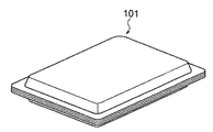
上記のようなヒートストレスの問題に鑑みて、従来から、衣服の内側に装着して体温の上昇を防ぐための冷却材の入った冷却パックが提案されている(特許文献1及び2参照)。例えば、図36〜38に示すような四角い板状の冷却パック101であって服の内側ポケット103、104、105に取り出し可能に収納することができるものがある。冷却パック101を装着することにより、着用者の体から放出される熱が冷却パック101内の冷却材に吸収されて、体温の上昇を防止する。冷却材としては、熱を吸収して固体から液体に物理相が変化する固液相変化材料(Phase Change Materials)が用いられる。この固液相変化材料は、常温で固化するものである。   In view of the problem of heat stress as described above, conventionally, a cooling pack containing a coolant for wearing on the inside of clothes to prevent an increase in body temperature has been proposed (see Patent Documents 1 and 2). For example, there is a rectangular plate-shaped cooling pack 101 as shown in FIGS. 36 to 38, which can be removably stored in the inner pockets 103, 104, 105 of clothes. By mounting the cooling pack 101, heat released from the wearer's body is absorbed by the coolant in the cooling pack 101, thereby preventing an increase in body temperature. As the coolant, a solid-liquid phase change material that absorbs heat and changes a physical phase from a solid to a liquid is used. This solid-liquid phase change material solidifies at room temperature.

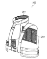
また、図40のように、長方形状の略平板状の保冷体201であって、冷やしても固化せずに常に柔軟性のあるゲル状の保冷材207が充填されたものも提案されている。この保冷体201は、図39に示すように衣服202の内側に取り付けて使用するもので、使用前に冷凍庫で冷却してから使用する。   Further, as shown in FIG. 40, a substantially flat plate-shaped cold insulator 201 that is always filled with a gel-like cold insulator 207 that does not solidify even when cooled is proposed. . The cold insulator 201 is used by being attached to the inside of the clothes 202 as shown in FIG. 39, and is used after being cooled in a freezer before use.

特開2003−328213号公報JP 2003-328213 A 特開2010−255152号公報JP 2010-255152 A

しかしながら、特許文献1のような平坦な板状の冷却パック101を用いる場合、常温で固体状に固まっているため、体に沿って柔軟に曲げることができず、結果的に体と冷却パック101の間に隙間ができてしまう。そのため、冷却パック101と体との密着性が低くなり、体から放出される熱を効率よく吸収できずに、冷却効率が下がる。   However, when the flat plate-like cooling pack 101 as in Patent Document 1 is used, since it is solidified at room temperature, it cannot be flexibly bent along the body. As a result, the body and the cooling pack 101 can be bent. There will be a gap between them. For this reason, the adhesion between the cooling pack 101 and the body is lowered, the heat released from the body cannot be efficiently absorbed, and the cooling efficiency is lowered.

また、例えば、冷却材が液化した状態で冷却パック101がポケット103、104、105に収納された衣服102をハンガーに掛けたままにすると、図41の点線で示すように液体状の冷却材が自重によりパック101の下部に過剰に溜まって膨らんだ形状に変形する。このように変形した状態のまま冷却材が冷やされて固化した場合、冷却パック101内で冷却材が厚い箇所と薄い箇所ができるため、再度使用する際に冷却効率にムラが出てしまう。それを防止するために、冷却材を冷やして固体状に戻すときは、いちいち冷却パック101を衣服102のポケット103、104、105から出して横置きにしなければならず、手間がかかった。また、衣服102に入れたまま保管しようとすれば、変形防止のために衣服102ごと横置きにする必要があり、保管場所に広いスペースをとらなければならないという問題もあった。   Further, for example, when the cooling pack 101 is left in a state where the cooling pack 101 is liquefied while the clothes 102 stored in the pockets 103, 104, and 105 are hung on the hanger, the liquid cooling material is changed as shown by the dotted line in FIG. 41. Due to its own weight, it deforms into a bulging shape that accumulates excessively in the lower part of the pack 101. When the coolant is cooled and solidified in such a deformed state, a thick portion and a thin portion of the coolant are formed in the cooling pack 101, so that unevenness in cooling efficiency occurs when the coolant is used again. In order to prevent this, when cooling the coolant back to the solid state, the cooling pack 101 must be taken out of the pockets 103, 104, 105 of the garment 102 and placed horizontally, which is troublesome. Further, if the clothes 102 are stored while being stored, it is necessary to place the clothes 102 horizontally to prevent deformation, and there is a problem that a large space must be taken in the storage place.

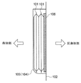
さらに、冷却パック101を装着するときは、熱の放出量の多い胸、背中等には冷却材を多めに配置する必要があり、腹部など熱があまり放出されない部位には冷却材は不要か少量でよい。しかし、板状の冷却パック101の場合、量を多くしようと図38に示すように、断熱パット106の内側に複数枚重ねて使用すると熱伝導効率が悪くなり、増えた量に比例する効果が期待できない。一方、冷却パック101の1枚の厚みを厚くすると冷却材が液相のときの変形がより大きくなってしまう。   Furthermore, when the cooling pack 101 is mounted, it is necessary to place a large amount of coolant on the chest, back, etc., where there is a large amount of heat release. It's okay. However, in the case of the plate-shaped cooling pack 101, as shown in FIG. 38 in order to increase the amount, if a plurality of sheets are stacked inside the heat insulating pad 106, the heat conduction efficiency deteriorates, and the effect proportional to the increased amount is obtained. I can't expect it. On the other hand, when the thickness of one cooling pack 101 is increased, deformation when the coolant is in the liquid phase becomes larger.

一方、特許文献2のような保冷体201は、長方形状の略平板状のパック208内にゲル状の保冷剤207が充填されているため、柔軟で体に密着しやすいが、特許文献1の冷却パックと同様に保冷剤207が自重によってパック208下部に溜まり易く、やはり図41の点線で示すような変形をする。そのため、保冷剤207の量を増やそうとしても、保冷体201を厚くすることができない。また、保冷材207は、相変化を起こす蓄熱材(比熱35cal/g)が40%で、残り60%が水(比熱1cal/g)という構成でできているため、100%が蓄熱材で構成されている固液相変化材料に比べて、熱吸収力が低く、長時間の低温持続効果は期待できない。   On the other hand, the cold insulator 201 as in Patent Document 2 is soft and easy to adhere to the body because the gel-like cold insulator 207 is filled in the rectangular substantially flat pack 208. As with the cooling pack, the cold-retaining agent 207 easily accumulates in the lower portion of the pack 208 due to its own weight, and also deforms as shown by the dotted line in FIG. Therefore, even if it is going to increase the quantity of the cold insulating agent 207, the cold insulating body 201 cannot be thickened. In addition, the heat insulating material 207 is composed of 40% heat storage material (specific heat 35 cal / g) causing phase change and 60% water (specific heat 1 cal / g), so that 100% is composed of heat storage material. Compared to solid-liquid phase change materials, the heat absorption is low, and long-term low temperature sustaining effects cannot be expected.

また、上記とは逆に固液相変化材料を寒冷環境下(冬季等の寒さを感じる環境下等)における身体の保温材として使用する場合、固液相変化材料が液相の状態で保温パックを身体に密着させ、放熱して保温効果を発揮するとともに固相に変化する。従って、液相の状態で図41にように保温パックが変形すると保温効果にムラが出てしまう。また、図37又は図40に示すような板状の保温パックの場合、固液相変化材料が液相の時に脚部等の周囲にぐるっと一周巻きつけた状態で固液相変化材料が固相になると、取り外しが困難になる。   Contrary to the above, when the solid-liquid phase change material is used as a body heat-retaining material in a cold environment (environment that feels cold in winter etc.), the heat-insulated pack with the solid-liquid phase change material in the liquid phase state Is in close contact with the body, radiates heat and exerts a heat retaining effect and changes to a solid phase. Therefore, when the heat retaining pack is deformed as shown in FIG. 41 in the liquid phase, the heat retaining effect is uneven. Further, in the case of a plate-shaped heat retaining pack as shown in FIG. 37 or FIG. 40, when the solid-liquid phase change material is in the liquid phase, the solid-liquid phase change material is solid-phased in a state of being wound around the periphery of the leg portion or the like. Then, it becomes difficult to remove.

本発明は上記のような問題点に鑑みてなされたものであり、着用者の体温上昇或いは体温低下を防止するために固液相変化材料を用いる体温調節パックについて、衣服の下に着るパックホルダーの内側に体温調節パックを配置した場合、固体状態でも体の形に沿って曲がることができ、冷却材または保温材として使われる固液相変化材料が液相であっても体温調節パックの天地に関わらず外形が変形せず、全体として略板形状となり、熱吸収力または放熱力の高い体温調節パックを提供することを主な目的とする。   The present invention has been made in view of the above problems, and a pack holder that is worn under clothing for a thermoregulation pack that uses a solid-liquid phase change material in order to prevent the body temperature of the wearer from increasing or decreasing. When the thermostat pack is placed inside the body, it can bend along the shape of the body even in the solid state, and even if the solid-liquid phase change material used as a coolant or heat insulator is in the liquid phase, the thermostat pack top and bottom Regardless of the shape, the main object is to provide a body temperature regulation pack that is substantially plate-shaped as a whole and has high heat absorption or heat dissipation.

本発明の体温調節パックは、内部に固液相変化材料が充填される体温調節パックにおいて、該体温調節パックは、複数の袋体から構成され、該複数の袋体の内部には前記固液相変化材料が隙間なく充填されていることを特徴とする。   The body temperature regulation pack of the present invention is a body temperature regulation pack in which a solid-liquid phase change material is filled, and the body temperature regulation pack is composed of a plurality of bags, and the solid-liquid is disposed inside the plurality of bags. The phase change material is filled without any gaps.

前記袋体の各々は、細長い円筒形状であることが好ましい。また、本発明の体温調節パックは、2枚のインナーシートの周囲の縁部を貼り合わせて形成されており、前記細長袋状部の各々は2枚の前記インナーシートを平行に複数ケ所溶着することにより分割されていてもよい。またさらに、本発明の体温調節パックの片面は断熱材で覆われてもよい。   Each of the bag bodies preferably has an elongated cylindrical shape. Moreover, the body temperature regulation pack of the present invention is formed by bonding the peripheral edges of two inner sheets, and each of the elongated bag-like parts welds the two inner sheets in parallel at a plurality of locations. It may be divided by. Furthermore, one side of the body temperature regulation pack of the present invention may be covered with a heat insulating material.

本発明の体温調整パックに利用される固液相変化材料は、酢酸ナトリウムを含有するものであってもよく、また、硫酸ナトリウムを含有するものであってもよく、またはノルマルパラフィンを含むものであってもよい。   The solid-liquid phase change material used for the body temperature regulation pack of the present invention may contain sodium acetate, may contain sodium sulfate, or contains normal paraffin. There may be.

本発明の別の局面によれば、体温調節パックを身体側に取り付ける胴体パックホルダーであって、該体温調節パックを任意の場所に着脱自在に取り付けることができることを特徴とする胴体パックホルダーを提供するものである。   According to another aspect of the present invention, there is provided a torso pack holder for attaching a body temperature regulation pack to the body side, wherein the body temperature regulation pack can be detachably attached to an arbitrary place. To do.

胴体パックホルダーは、着用者の胸部を覆う前面部と、着用者の背中を覆う後面部とを有し、該前面部と該後面部とは、それぞれ着脱可能に接続されてもよい。また、該前面部と該後面部とは、それぞれ伸縮自在な紐状体によって接続されていてもよい。   The torso pack holder has a front part covering the chest of the wearer and a rear part covering the back of the wearer, and the front part and the rear part may be detachably connected to each other. Further, the front surface portion and the rear surface portion may be connected to each other by a stretchable string-like body.

本発明のさらに別の局面によれば、体温調節パックを首周りや脚部に着脱自在に取り付けることを特徴とする襟部パックホルダーや脚部パックホルダーを提供するものである。   According to still another aspect of the present invention, there is provided a collar pack holder and a leg pack holder, wherein the body temperature regulation pack is detachably attached to the neck and legs.

本発明の体温調節パックは、身体の冷却を目的として使用する場合、熱吸収力の高い固液相変化材料を使用して、固相となっても体の形に沿って曲がるため、体への密着性が高く、冷却効率が良い。さらに、単位面積当たりの固液相変化材料の量を増やしても変形しないため、固液相変化材料の量を体の部位に応じて適宜調整することができる。そのため、高温環境下におけるヒートストレスを効率よく軽減することができる。   When the body temperature regulation pack of the present invention is used for the purpose of cooling the body, it uses a solid-liquid phase change material having a high heat absorption ability and bends along the shape of the body even if it becomes a solid phase. The adhesion is high and the cooling efficiency is good. Further, since the deformation does not occur even when the amount of the solid-liquid phase change material per unit area is increased, the amount of the solid-liquid phase change material can be appropriately adjusted according to the body part. Therefore, heat stress in a high temperature environment can be efficiently reduced.

また、冷却材として固液相変化材料を使用するため、固液相変化材料が液相になって冷却機能を失った場合でも、冷やすことで再び固相に戻し、繰り返して何度でも使用することができる。従って、使い捨ての冷却材と比べて経済的である。   In addition, since a solid-liquid phase change material is used as a coolant, even if the solid-liquid phase change material becomes a liquid phase and loses its cooling function, it is returned to the solid phase by cooling and used repeatedly. be able to. Therefore, it is more economical than a disposable coolant.

さらに、体温調節パックをパックホルダーに任意の場所に着脱自在に取り付けることにより、必要な場所の熱を吸収するとともに熱の逃げ場もつくることができる。   Furthermore, by attaching the body temperature regulation pack to the pack holder in an arbitrary position, it is possible to absorb heat at a necessary place and to create a heat escape place.

また同時に、本発明の体温調整パックを身体の保温目的で利用する場合、液相の状態でも体温調節パック自体が変形しないため、ムラなく身体の必要な箇所を保温することができる。さらに、固液相変化材料が固相となっても、自在に曲げたり延ばしたりすることが可能であるため、体の形に沿って曲がっていたものを容易に取り外すことができる。従って、冬場の屋外作業、或いは暖房器具のない作業所において、着用者の上半身の保温だけでなく、衣服の外側からふくらはぎ等に巻き付けて足元を保温することも可能となる。   At the same time, when the body temperature regulation pack of the present invention is used for the purpose of keeping the body warm, the body temperature regulation pack itself is not deformed even in the liquid phase, so that the necessary part of the body can be kept warm. Furthermore, even if the solid-liquid phase change material becomes a solid phase, it can be bent and extended freely, so that a material bent along the shape of the body can be easily removed. Therefore, in winter work in winter, or in a work place without a heater, it is possible not only to keep the upper body of the wearer warm, but also to keep the feet warm by wrapping around a calf or the like from the outside of the clothes.

本発明の体温調節パックの斜視図である。It is a perspective view of the body temperature regulation pack of the present invention. 図1に示す体温調節パックの第1の実施形態の断面の斜視図である。It is a perspective view of the cross section of 1st Embodiment of the body temperature regulation pack shown in FIG. 図2に示す体温調節パックの製造工程を示す図で、1対のインナーシートを重ねて、インナーパックを成形した様子を示す概略図である。It is a figure which shows the manufacturing process of the body temperature regulation pack shown in FIG. 2, and is the schematic which shows a mode that a pair of inner sheet | seat was piled up and the inner pack was shape | molded. 図2に示す体温調節パックの製造工程を示す図で、インナーパックの細長袋状部に固液相変化材料を注入した様子を示す概略図である。It is a figure which shows the manufacturing process of the body temperature regulation pack shown in FIG. 2, and is the schematic which shows a mode that the solid-liquid phase change material was inject | poured into the elongate bag-like part of the inner pack. 図2に示す体温調節パックの製造工程を示す図で、注入した固液相変化材料が固相になった後に真空パックを施した様子を示す概略図である。It is a figure which shows the manufacturing process of the body temperature regulation pack shown in FIG. 2, and is the schematic which shows a mode that the vacuum pack was given after the inject | poured solid-liquid phase change material became a solid phase. 図2に示す体温調節パックの製造工程を示す図で、固液相変化材料を再び液相にした後、上部の縁部を折り曲げた様子を示す概略図である。It is a figure which shows the manufacturing process of the body temperature regulation pack shown in FIG. 2, Comprising: After making solid-liquid phase change material into a liquid phase again, it is the schematic which shows a mode that the upper edge part was bent. 図2に示す体温調節パックの製造工程を示す図で、周囲の縁部を全て折り曲げて、インナーパックに固液相変化材料が隙間無く充填されている状態にした様子を示す概略図である。It is a figure which shows the manufacturing process of the body temperature regulation pack shown in FIG. 2, and is the schematic which shows a mode that all the surrounding edge parts were bend | folded and the inner-pack was filled with the solid-liquid phase change material without the clearance gap. 図2に示す体温調節パックの製造工程を示す図で、インナーパックに断熱材を取り付けた様子を示す概略図である。It is a figure which shows the manufacturing process of the body temperature regulation pack shown in FIG. 2, and is the schematic which shows a mode that the heat insulating material was attached to the inner pack. 図2に示す体温調節パックの製造工程を示す図で、断熱材を取り付けたインナーパックをアウターパックで被覆した様子を示す概略図である。It is a figure which shows the manufacturing process of the body temperature regulation pack shown in FIG. 2, and is the schematic which shows a mode that the inner pack which attached the heat insulating material was coat | covered with the outer pack. 図2に示す体温調節パックの製造工程を示す図で、インナーパックをアウターパックで被覆した後に、真空パックを施して体温調節パックを完成させた様子を示す概略図である。It is a figure which shows the manufacturing process of the body temperature regulation pack shown in FIG. 2, Comprising: After coat | covering an inner pack with an outer pack, it is the schematic which shows a mode that the vacuum pack was given and the body temperature regulation pack was completed. 図2に示す完成後の体温調節パックの柔軟性を示す概略図である。It is the schematic which shows the softness | flexibility of the body temperature regulation pack after completion shown in FIG. 図2に示す体温調節パックを複数重ねて保管する様子を示す概略図である。It is the schematic which shows a mode that two or more body temperature regulation packs shown in FIG. 2 are stored. 本発明の実施形態2に係る細長袋体の製造工程を示す図で、一方の端部を溶着した様子を示す概略図である。It is a figure which shows the manufacturing process of the elongate bag body which concerns on Embodiment 2 of this invention, and is the schematic which shows a mode that one edge part was welded. 本発明の実施形態2に係る細長袋体の製造工程を示す図で、内部に固液相変化材料を充填した後に、注入口となっていた端部を溶着した様子を示す概略図である。It is a figure which shows the manufacturing process of the elongate bag body which concerns on Embodiment 2 of this invention, and is a schematic diagram which shows a mode that the edge part used as the injection port was welded, after filling a solid-liquid phase change material inside. 本発明の実施形態2に係る細長袋体の製造工程を示す図で、両端の溶着部を内側に折り曲げた様子を示す概略図である。It is a figure which shows the manufacturing process of the elongate bag body which concerns on Embodiment 2 of this invention, and is the schematic which shows a mode that the welding part of both ends was bend | folded inside. 図1に示す体温調節パックの実施形態2による製造工程を示す図で、図15示す細長袋体を細長袋体整列部材の上に平行方向に並列に配置した様子を示す概略図である。It is a figure which shows the manufacturing process by Embodiment 2 of the body temperature regulation pack shown in FIG. 1, and is the schematic which shows a mode that the elongate bag body shown in FIG. 15 is arrange | positioned in parallel on the elongate bag body alignment member. 図1に示す体温調節パックの実施形態2による製造工程を示す図で、図16に示す細長袋体整列部材の斜視図である。It is a figure which shows the manufacturing process by Embodiment 2 of the body temperature regulation pack shown in FIG. 1, and is a perspective view of the elongate bag body alignment member shown in FIG. 図1に示す体温調節パックの実施形態2による製造工程を示す図で、図16に示す複数の細長袋体に断熱材を取り付けた様子を示す概略図である。It is a figure which shows the manufacturing process by Embodiment 2 of the body temperature regulation pack shown in FIG. 1, and is the schematic which shows a mode that the heat insulating material was attached to the some elongate bag body shown in FIG. 図1に示す体温調節パックの実施形態2による製造工程を示す図で、断熱材を取り付けた一群の細長袋体をアウターパックで被覆した様子を示す概略図である。It is a figure which shows the manufacturing process by Embodiment 2 of the body temperature regulation pack shown in FIG. 1, and is the schematic which shows a mode that the group of elongate bag bodies which attached the heat insulating material were coat | covered with the outer pack. 図1に示す体温調節パックの実施形態2による製造工程を示す図で、一群の細長袋体をアウターパックで被覆した後に、真空パックを施して体温調節パックを完成させた様子を示す概略図である。It is a figure which shows the manufacturing process by Embodiment 2 of the body temperature regulation pack shown in FIG. 1, Comprising: After coat | covering a group of elongate bag bodies with an outer pack, it is the schematic which shows a mode that the vacuum pack was given and the body temperature regulation pack was completed. is there. 図1に示す体温調節パックの実施形態2による製造工程を示す図で、図16に示す複数の細長袋体に細長袋体整列部材と別実施形態の断熱材を取り付ける様子を示す概略図である。It is a figure which shows the manufacturing process by Embodiment 2 of the body temperature regulation pack shown in FIG. 1, and is the schematic which shows a mode that the heat insulating material of another embodiment is attached to the some elongated bag body shown in FIG. . 本発明の体温調節パックに充填する固液相変化材料の量を適宜変化させた様子を示す図である。幅を20cmとして、上から細長袋状部の直径を2cm、2.5cm、3cm、4cm、4.5cm及び5cmと設定したものである。It is a figure which shows a mode that the quantity of the solid-liquid phase change material with which the body temperature regulation pack of this invention is filled was changed suitably. The width is set to 20 cm, and the diameter of the elongated bag-like portion is set to 2 cm, 2.5 cm, 3 cm, 4 cm, 4.5 cm, and 5 cm from the top. 図1に示す体温調節パックを冷却材として使用する場合であって、この体温調節パックを冷蔵庫内で冷却するときに使用する冷却台を示す概略図である。FIG. 2 is a schematic diagram showing a cooling table used when the body temperature regulation pack shown in FIG. 1 is used as a coolant and the body temperature regulation pack is cooled in a refrigerator. 図1に示す体温調節パックを図23に示す冷却台を使って冷却する様子を示す概略図である。It is the schematic which shows a mode that the body temperature regulation pack shown in FIG. 1 is cooled using the cooling stand shown in FIG. 首周りに取り付ける体温調節パックの概略図である。It is the schematic of the body temperature regulation pack attached around the neck. 図25に示す体温調節パックを挿入するメッシュ製のメッシュ袋を示す斜視図である。It is a perspective view which shows the mesh bag made from a mesh which inserts the body temperature regulation pack shown in FIG. 図26に示すメッシュ製のメッシュ袋の表面と裏面を示す平面図である。It is a top view which shows the surface and back surface of the mesh bag made from a mesh shown in FIG. 本願の実施例の体温調節パックを取り付けるための、専用のメッシュ製のパックホルダーを示す正面図である。It is a front view which shows the pack holder made from a mesh for attaching the body temperature regulation pack of the Example of this application. 図28に示すパックホルダーの背面図である。It is a rear view of the pack holder shown in FIG. 図28に示すパックホルダーの側面図である。It is a side view of the pack holder shown in FIG. 図28に示すパックホルダーの前面部の表面と裏面を示す図である。It is a figure which shows the surface and back surface of the front part of the pack holder shown in FIG. 図28に示すパックホルダーの後面部の表面と裏面を示す図である。It is a figure which shows the surface and back surface of the rear surface part of the pack holder shown in FIG. 図31に示す前面部と図32に示す後面部とを紐状体で接続した様子を示す図である。It is a figure which shows a mode that the front part shown in FIG. 31 and the rear surface part shown in FIG. 32 were connected with the string-like body. 図28に示すパックホルダーの襟部の表面と裏面及び変形例を示す図である。It is a figure which shows the surface of the collar part of a pack holder shown in FIG. 28, a back surface, and a modification. 脚部パックホルダーを示す図である。It is a figure which shows a leg part pack holder. 従来の冷却パック取り付け用ベストを示す斜視図である。It is a perspective view which shows the vest for the conventional cooling pack attachment. 図36に示す従来の冷却パックを示す斜視図である。It is a perspective view which shows the conventional cooling pack shown in FIG. 図36に示す従来の冷却パックを重ねて使用する状態を示す断面図である。It is sectional drawing which shows the state which uses the conventional cooling pack shown in FIG. 36 in piles. 従来の冷却パック取り付け用ベストを示す斜視図である。It is a perspective view which shows the vest for the conventional cooling pack attachment. 図39に示す従来の冷却パックを示す斜視図である。It is a perspective view which shows the conventional cooling pack shown in FIG. 従来の冷却パックとその変形を示す立面図である。It is an elevation view showing a conventional cooling pack and its deformation.

以下、本発明の好適な実施形態について、図面を参照しつつ説明する。   Hereinafter, preferred embodiments of the present invention will be described with reference to the drawings.

[体温調節パック]
(実施形態1)
まず、後述するパックホルダー2(図28参照)に取り付けて使用する体温調節パック1について説明する。
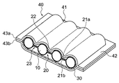
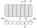
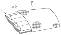
図1に示すように、体温調節パック1全体は略板状の矩形に形成されており、平行に配列された複数の袋体Tを備えている。図2に示すように、実施形態1では、体温調節パック1の内部は複数の細長袋状部22に分かれており、体温調節パック1は各々の細長袋状部22の間の後述する溶着部23を節として柔軟に曲げることができる。なお、体温調節パック1の形状は、本願実施の形態に係る矩形に限定されず、他の形でもよい。
[Body temperature control pack]
(Embodiment 1)
First, the body temperature regulation pack 1 used by being attached to a pack holder 2 (see FIG. 28) described later will be described.
As shown in FIG. 1, the whole body temperature regulation pack 1 is formed in a substantially plate-like rectangle, and includes a plurality of bag bodies T arranged in parallel. As shown in FIG. 2, in the first embodiment, the inside of the body temperature regulation pack 1 is divided into a plurality of elongated bag-like portions 22, and the body temperature regulation pack 1 is a welding portion described later between each of the elongated bag-like portions 22. It can be flexibly bent with 23 as a node. In addition, the shape of the body temperature regulation pack 1 is not limited to the rectangle according to the present embodiment, and may be another shape.

体温調節パック1は、固液相変化材料10が充填された細長袋状部22と、複数の細長袋状部22からなるインナーパック20と、インナーパック20の一方の面を覆う断熱材30と、断熱材30が取り付けられたインナーパック20の全体を被覆するアウターパック40とを有している。そして、体温調節パック1の表面はアウターパック40内部の細長袋状部22の形に沿った凹凸形状を有している。   The body temperature regulation pack 1 includes an elongated bag-shaped portion 22 filled with a solid-liquid phase change material 10, an inner pack 20 composed of a plurality of elongated bag-shaped portions 22, and a heat insulating material 30 covering one surface of the inner pack 20. The outer pack 40 covers the entire inner pack 20 to which the heat insulating material 30 is attached. And the surface of the body temperature regulation pack 1 has the uneven | corrugated shape along the shape of the elongate bag-shaped part 22 inside the outer pack 40.

インナーパック20は、1対のインナーシート21a,21bを有している。本実施形態では、同形状及び同素材である2枚のインナーシート21a,21bを用いているが、1枚のシートを2つ折りにして1対にしてもよい。この2枚のインナーシート21a,21bを互いに重ね合わせ、周りの縁部25を溶着などによって貼り合わせることでインナーパック20が形成される。また、貼り合わされた一対の2辺の縁部25の間に平行に複数の縦長の溶着部23を設けることで、溶着部23どうしの間に細長袋状部22が形成される。本発明では、インナーシート21a、21bを平行に等間隔で溶着してあるが、これに限らず溶着の間隔を適宜変えることで、ひとつひとつの細長袋状部22の大きさを変えることができる。   The inner pack 20 has a pair of inner sheets 21a and 21b. In the present embodiment, the two inner sheets 21a and 21b having the same shape and the same material are used, but one sheet may be folded into a pair. The two inner sheets 21a and 21b are overlapped with each other, and the peripheral edge 25 is bonded together by welding or the like to form the inner pack 20. Further, by providing a plurality of vertically long welded portions 23 in parallel between a pair of two edge portions 25 bonded together, an elongated bag-like portion 22 is formed between the welded portions 23. In the present invention, the inner sheets 21a and 21b are welded in parallel at equal intervals. However, the present invention is not limited to this, and the size of each elongated bag-like portion 22 can be changed by appropriately changing the welding interval.

インナーシート21a、21bは、シート状のポリエチレンとアルミニウム箔とシート状のナイロン(登録商標)とを貼り合わせた3層構造を有している。これらの3層は、インナーシート21a、21bをインナーパック20に用いたときに、インナーパック20の内側からインナーパック20の外側へ順に、ポリエチレンとアルミニウム箔とナイロン(登録商標)とが積層されるように配置される。この構造によって、インナーシート21a,21bは柔軟性があり、かつ高い強度を有し、破損しにくくなる。また、インナーシート21a,21bにアルミニウム箔を用いることにより、水蒸気バリア性が向上し、インナーパック20の内部からの水分の蒸散が防止され、固液相変化材料10の機能の損失を防止する。また、アルミニウム箔を用いることによって、熱伝導性が向上して冷却効率が高くなる。さらに、インナーシート21a、21bの外側表面にナイロン(登録商標)を使用することにより、耐摩耗性が向上する。なお、インナーシート21a、21bは柔軟かつ十分な強度を有し、内部に封入された固液相変化材料10が漏出しないものであれば、本実施例の材料に特に限定されない。   The inner sheets 21a and 21b have a three-layer structure in which sheet-like polyethylene, aluminum foil, and sheet-like nylon (registered trademark) are bonded together. In these three layers, polyethylene, aluminum foil, and nylon (registered trademark) are laminated in order from the inner side of the inner pack 20 to the outer side of the inner pack 20 when the inner sheets 21a and 21b are used in the inner pack 20. Are arranged as follows. With this structure, the inner sheets 21a and 21b are flexible and have high strength and are not easily damaged. Moreover, by using aluminum foil for the inner sheets 21a and 21b, the water vapor barrier property is improved, the evaporation of moisture from the inside of the inner pack 20 is prevented, and the loss of the function of the solid-liquid phase change material 10 is prevented. Further, by using the aluminum foil, the thermal conductivity is improved and the cooling efficiency is increased. Furthermore, wear resistance is improved by using nylon (registered trademark) on the outer surfaces of the inner sheets 21a and 21b. The inner sheets 21a and 21b are not particularly limited to the materials of the present embodiment as long as they are flexible and have sufficient strength and the solid-liquid phase change material 10 enclosed therein does not leak.

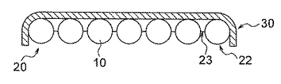
細長袋状部22の内部には、固液相変化材料10が細長袋状部の内容量いっぱいに隙間無く充填されており、細長い円柱形状となっている。このため、固液相変化材料10が液相の状態で体温調節パック1を縦方向に配置した場合でも、細長袋状部22に撓みが生じる余裕がないため、細長袋状部22は変形することがない。また、平行方向に複数の細長袋状部22が、柔軟性のある溶着部23を介して並列しているため、冷却剤10が固相になった場合でも、図11に示すように、溶着部23を節として体温調節パック1を体の形に沿って曲げることが可能となり、体温調節パック1の人体への密着性がより高くなる。さらに、円柱形状の細長袋状部22を横方向に並列したことにより、全体として表面に凹凸形状をもつ略板形状となっている。そのため、複数の体温調節パック1を保管するときは、図12に示すように安定して重ねて保管することができ、余計なスペースをとらない。なお、ここでもし、図37及び図40のような従来の平坦な板状の体温調節パックを液相でも変形させないために、冷却材を隙間無く充填した場合は、パック全体が横から見るとラグビーボール状に中央部分が膨らんだ形状となってしまい、安定して重ねて保管することができず、固相の時は体への密着性が非常に悪くなる。   The elongate bag-shaped portion 22 is filled with the solid-liquid phase change material 10 to fill the inner volume of the elongate bag-shaped portion without a gap, and has an elongated cylindrical shape. For this reason, even when the body temperature regulation pack 1 is arranged in the vertical direction while the solid-liquid phase change material 10 is in a liquid phase, the elongated bag-like portion 22 is deformed because there is no room for bending in the elongated bag-like portion 22. There is nothing. Further, since the plurality of elongated bag-like portions 22 are arranged in parallel through the flexible welded portion 23 in the parallel direction, even when the coolant 10 becomes a solid phase, as shown in FIG. The body temperature regulation pack 1 can be bent along the shape of the body with the portion 23 as a node, and the adhesion of the body temperature regulation pack 1 to the human body becomes higher. Further, the cylindrical elongated bag-like portions 22 are juxtaposed in the lateral direction, so that the overall surface has a substantially plate shape with a concavo-convex shape. Therefore, when storing a plurality of body temperature regulation packs 1, as shown in FIG. 12, it can be stably stacked and stored, and no extra space is taken up. Here, in order not to deform the conventional flat plate-shaped body temperature regulation pack as shown in FIGS. 37 and 40 even in the liquid phase, when the coolant is filled without any gap, the entire pack is viewed from the side. The central portion of the rugby ball is swollen, and cannot be stably stacked and stored, and the adhesion to the body becomes very poor when in the solid phase.

体温調節パック1は、固液相変化材料10の量を増やしても変形する心配が無いため、図22に示すように、細長袋状部22は適宜直径を変えることにより、体の部位や必要な冷却機能保持時間または保温機能保持時間に応じて、固液相変化材料10の量を調整することができる。具体的には、固液相変化材料10を冷却材として使用する場合は、熱の放出量の多い胸、背中等には固液相変化材料10を多めに配置し(円筒状の細長袋状部22´の直径を大きくする/図22の下側)、熱があまり放出されない部位には固液相変化材料を少量にする(円筒状の細長袋状部22´´の直径を小さくする/図22の上側)というような調整をする。また、細長袋状部22の円形断面それぞれの一部が身体に接触していれば、体表面から放出される熱を効率よく吸収し、体温の異常上昇を防止することができる。また逆に、固液相変化材料10を保温材として使用する場合には、熱を放出して身体に伝熱し、効率よく暖めることができる。   Since the body temperature regulation pack 1 has no fear of being deformed even when the amount of the solid-liquid phase change material 10 is increased, as shown in FIG. The amount of the solid-liquid phase change material 10 can be adjusted according to the cooling function holding time or the heat holding function holding time. Specifically, when the solid-liquid phase change material 10 is used as a coolant, a large amount of the solid-liquid phase change material 10 is disposed on the chest, back, etc. where the amount of heat is released (cylindrical elongated bag shape). The diameter of the portion 22 'is increased / lower side of FIG. 22 and the solid-liquid phase change material is reduced in a small amount at the portion where the heat is not released very much (the diameter of the cylindrical elongated bag-shaped portion 22' 'is decreased / Adjustment such as the upper side in FIG. Further, if a part of each of the circular cross sections of the elongated bag-like portion 22 is in contact with the body, heat released from the body surface can be efficiently absorbed and an abnormal increase in body temperature can be prevented. On the other hand, when the solid-liquid phase change material 10 is used as a heat insulating material, heat can be released and transferred to the body to efficiently warm it.

固液相変化材料(phase change materials)10は、まず冷却材として使用することができる。固液相変化材料は固相状態から液体状態に変わる際、潜熱と呼ばれる物質の結合状態を変化させるために、温度を変化させることなく吸収される熱エネルギーを必要とする。すなわち、固液相変化材料10は、着用者の体から放出される熱エネルギーを吸収して、固体状態から液体状態へと変化する間、固液相変化材料10の温度は融点と呼ばれる一定温度に固定されるため、着用者の体温が上がりすぎるのを防止する。固液相変化材料10の融点は、一般的に言われている安静時における人体の体表面温度(32℃)よりも低い温度であることが好ましい。本実施例では固液相変化材料10の基材として硫酸ナトリウム10水和物を用いており、この硫酸ナトリウム10水和物には、水和物として安定的な可逆性を保持するために過冷却防止剤等の添加剤を入れたものを使用している。硫酸ナトリウム10水和物そのものの融点は32℃強であるが、過冷却のために、固液相変化材料10は32℃よりも低い25℃〜28℃の範囲で、一部ずつ固液転換を起こしつつ相変化する。そのため、従来の固液相変化材料を用いた冷却材の融点が0℃付近の温度であるのに比べ、体を冷やしすぎることによる凍傷のおそれや、身体機能が低下するおそれがない。また、相変化温度が25℃〜28℃の範囲であれば、安静時(熱吸着を必要としない時)は肌着・作業着の上から体温調節パック1を当てても着用者はほとんど冷たいとは感じず、固液相変化材料10は相変化を起こさないが、身体に負荷がかかり体表面温度が上昇すると、急に冷たさを感じるようになり、固液相変化材料10の相変化が開始する。一方、0℃付近で相変化する従来の固液相変化材料を用いた冷却材では、平常体温時で固液相変化を起こすため、体温の異常上昇防止が必要となる時点では、既に液化して冷却機能を失ってしまう。この点が0℃付近で相変化をおこす従来の冷却材との大きな違いである。   The solid-liquid phase change materials 10 can first be used as a coolant. When the solid-liquid phase change material changes from the solid phase state to the liquid state, it requires thermal energy that is absorbed without changing the temperature in order to change the binding state of a substance called latent heat. That is, while the solid-liquid phase change material 10 absorbs heat energy released from the wearer's body and changes from a solid state to a liquid state, the temperature of the solid-liquid phase change material 10 is a constant temperature called a melting point. This prevents the body temperature of the wearer from rising too much. The melting point of the solid-liquid phase change material 10 is preferably a temperature lower than the generally known body surface temperature (32 ° C.) at rest. In this example, sodium sulfate decahydrate is used as the base material of the solid-liquid phase change material 10, and this sodium sulfate decahydrate contains an excess of hydrate to maintain stable reversibility. The one containing additives such as cooling inhibitors is used. Although the melting point of sodium sulfate decahydrate itself is slightly over 32 ° C, due to supercooling, the solid-liquid phase change material 10 is partially converted into a solid-liquid solution in the range of 25 ° C to 28 ° C lower than 32 ° C. The phase changes while waking up. Therefore, there is no fear of frostbite caused by overcooling the body or deterioration of physical function as compared with the case where the melting point of the coolant using the conventional solid-liquid phase change material is around 0 ° C. In addition, if the phase change temperature is in the range of 25 ° C. to 28 ° C., the wearer is almost cold even when the body temperature control pack 1 is applied from the top of the underwear / work clothes when resting (when heat adsorption is not required). The solid-liquid phase change material 10 does not cause a phase change, but when a load is applied to the body and the body surface temperature rises, it suddenly feels cold, and the phase change of the solid-liquid phase change material 10 Start. On the other hand, a coolant using a conventional solid-liquid phase change material that changes phase around 0 ° C causes a solid-liquid phase change at normal body temperature, so it has already liquefied when it is necessary to prevent an abnormal rise in body temperature. Will lose the cooling function. This is a significant difference from the conventional coolant that causes a phase change near 0 ° C.

さらに、高温環境下で体温調節パック1を使用して熱を吸収した固液相変化材料10が液相となった場合であっても、比較的短時間で固体状態に戻すことができる。例えば、体温調節パック1を氷水に数分間浸して冷却することで容易に放熱し、冷蔵庫や保冷庫等の設備を使わずに固体状態に戻すことができる。一般的には、細長袋状部22が40mm超の直径の場合、10℃前後の温度で、一晩で固体状態に戻る。また、固液相変化材料10が完全に液相になって冷却機能を失った場合でも、冷やして放熱させることで再び固相に戻し、繰り返して何度でも使用することができる。従って、使い捨ての冷却材と比べて経済的である。なお、固液相変化材料10の基材は本実施例の硫酸ナトリウム10水和物に限定されず、100%の固液相変化をするものであり、相変化温度が室温の範囲(15℃程度から35℃程度)である材料であればよく、他の無機塩水和物系の物質(燐酸ナトリウム12水和物等)やノルマルパラフィン(n−ヘプタデカン、n−オクダデカン、n−ノナデカン等)を使用してもよい。   Furthermore, even when the solid-liquid phase change material 10 that has absorbed heat using the body temperature regulation pack 1 in a high temperature environment becomes a liquid phase, it can be returned to a solid state in a relatively short time. For example, the body temperature regulation pack 1 can be easily dissipated by cooling it by immersing it in ice water for several minutes, and can be returned to a solid state without using equipment such as a refrigerator or a cold storage. Generally, when the elongated bag-like portion 22 has a diameter of more than 40 mm, it returns to a solid state overnight at a temperature of around 10 ° C. Further, even when the solid-liquid phase change material 10 is completely in a liquid phase and loses its cooling function, it can be returned to the solid phase by cooling and dissipating heat, and it can be used over and over again. Therefore, it is more economical than a disposable coolant. In addition, the base material of the solid-liquid phase change material 10 is not limited to the sodium sulfate decahydrate of the present embodiment, and is 100% solid-liquid phase change, and the phase change temperature is in the range of room temperature (15 ° C. Any other material such as sodium phosphate dodecahydrate or normal paraffin (n-heptadecane, n-okdadecane, n-nonadecane, etc.). May be used.

本願発明の冷却材10は、固液相変化材料で100%構成されている。一方、図40に示す保冷体201の冷却材207は、相変化材料が40%で、残りは比熱1以下の水を主体とした内容物であるため、冷やしても固相になることなく常に柔軟性をもつ。しかしながら、単純計算により1パック100gで熱吸収力を計算すると、25〜30℃で相変化を起こす蓄熱剤の相変化時の熱吸収35cal/gとして、25℃から30℃に温度上昇させた場合、固液相変化材料40%、比熱1の水が60%で構成されている図40の保冷体201の熱吸収量は、
40g×35cal+60g×1cal×5℃=1700cal
対して、固液相変化材料100%で構成されている本発明の体温調節パック1の熱吸収量は、
100g×35cal=3500cal
となる。従って、本発明の体温調節パック1と図40に示す従来の保冷体とでは、熱吸収力に2倍程度の差があり、後述するベスト状のパックホルダー2に取り付けて使用するものとしては低温持続効果に決定的な違いである。ここで、本発明に使用される体温調節パック1は、前述のように体の形に沿って自由に曲げることができるため、冷却材10の固液相変化材料を100%とすることによる高い熱吸収能力と、人体への追随性を両立している。
The coolant 10 of the present invention is 100% composed of a solid-liquid phase change material. On the other hand, the coolant 207 of the cold insulator 201 shown in FIG. 40 is a content mainly composed of water with a phase change material of 40% and a specific heat of 1 or less. Be flexible. However, when the heat absorption capacity is calculated with 100 g per pack by simple calculation, when the temperature is increased from 25 ° C. to 30 ° C. as heat absorption 35 cal / g at the time of phase change of the heat storage agent that causes phase change at 25-30 ° C. The heat absorption amount of the cold insulator 201 in FIG. 40, which is composed of 40% solid-liquid phase change material and 60% water with specific heat 1,
40 g × 35 cal + 60 g × 1 cal × 5 ° C. = 1700 cal
On the other hand, the heat absorption amount of the body temperature regulation pack 1 of the present invention composed of 100% solid-liquid phase change material is:
100g x 35cal = 3500cal
It becomes. Therefore, the body temperature regulation pack 1 of the present invention and the conventional cold insulator shown in FIG. 40 have a difference of about two times in the heat absorption capacity, and it is a low temperature to be used by attaching to the vest-shaped pack holder 2 described later. It is a decisive difference in sustained effect. Here, since the body temperature regulation pack 1 used in the present invention can be freely bent along the shape of the body as described above, it is high by setting the solid-liquid phase change material of the coolant 10 to 100%. It has both heat absorption capability and followability to the human body.

固液相変化材料10は固相で結晶化しており、この結晶が完全に融け切ると液相に戻すのが困難になる。具体的には、例えば100℃の熱湯で体温調節パック1を加熱すると数分の間に結晶は完全になくなる。この状態で、常温下(22℃程度)に放置し固液相変化を待つと長い時間がかかるだけでなく、固相に戻らなくなる可能性がある。その場合は、いったん10℃程度に冷やして内部に少しでも結晶ができれば、あとは常温下で固相に戻すことができる。すなわち換言すると、体温調節パック1内に少量でも結晶を残すことによって液相から固相への相変化に費やすエネルギーを小さくすることができる。従って、体温調節パック1を身体に調節するときは、必要とする大きさよりも少し口径を大きくして、完全な結晶溶解を防ぐ工夫をする必要がある。   The solid-liquid phase change material 10 is crystallized in the solid phase, and when the crystals are completely melted, it becomes difficult to return to the liquid phase. Specifically, for example, when the body temperature regulation pack 1 is heated with hot water at 100 ° C., the crystals disappear completely within a few minutes. In this state, if it is left at room temperature (about 22 ° C.) and waits for a solid-liquid phase change, it may take a long time and may not return to the solid phase. In that case, once it is cooled to about 10 ° C. and crystals are formed in the interior, it can be returned to the solid phase at room temperature. In other words, the energy spent for the phase change from the liquid phase to the solid phase can be reduced by leaving a small amount of crystals in the body temperature regulation pack 1. Therefore, when adjusting the body temperature regulation pack 1 to the body, it is necessary to devise a technique to prevent complete crystal dissolution by making the caliber slightly larger than the required size.

ここで、図22に示すような直径の大きな細長袋状部22´を有する体温調節パック1は、直径の小さい細長袋状部22´´を有する体温調節パック1よりも、液相から固相に変化するために要する時間が長くなる。そのため、作業効率をあげるために、直径の大きな細長袋状部22´を有する体温調節パック1の機能を効率よく回復させなければならない場合は、常温で放熱させるよりも冷蔵庫に入れて冷却する方法が推奨される。この時、複数の体温調節パック1を冷蔵庫内で冷却する場合は、図23及び図24で示す冷却台11を使用する。   Here, the body temperature regulation pack 1 having the elongated bag-like portion 22 ′ having a large diameter as shown in FIG. 22 is more solid from the liquid phase than the body temperature regulation pack 1 having the elongated bag-like portion 22 ″ having the smaller diameter. It takes longer time to change. Therefore, in order to improve work efficiency, when the function of the body temperature regulation pack 1 having the elongated bag-like portion 22 'having a large diameter must be restored efficiently, a method of cooling in a refrigerator rather than releasing heat at room temperature Is recommended. At this time, when cooling a plurality of body temperature regulation packs 1 in the refrigerator, the cooling table 11 shown in FIGS. 23 and 24 is used.

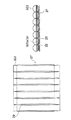
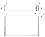
冷却台11は、図23に示すように、上から見ると略長方形状をしており向かい合う2つの短辺に立上り部12を有する。また、図24に示すように、立上がり部12の上端に沿って、冷却台11の内側向きに立上り部12とは直角になるように係止部13が設けられている。立上り部12の高さHは体温調節パック1の厚さhよりも高くなるように設定されている。なお、冷却台11はアルミ板で作られている。但し、冷気が通って循環し易い形状であれば、冷却台11の形状は本実施例に限定されず、向かい合う2つの長辺に立上り部12を有してもよい。さらに冷却台11の素材もアルミ板に限られず、高い熱伝導性を有する素材であればよい。   As shown in FIG. 23, the cooling table 11 has a substantially rectangular shape when viewed from above, and has rising portions 12 on two short sides facing each other. Further, as shown in FIG. 24, a locking portion 13 is provided along the upper end of the rising portion 12 so as to be perpendicular to the rising portion 12 inward of the cooling table 11. The height H of the rising portion 12 is set to be higher than the thickness h of the body temperature regulation pack 1. The cooling table 11 is made of an aluminum plate. However, the shape of the cooling stand 11 is not limited to the present embodiment as long as it is easy to circulate through the cold air, and may have the rising portions 12 on the two long sides facing each other. Furthermore, the material of the cooling table 11 is not limited to the aluminum plate, and may be a material having high thermal conductivity.

冷却台11の使用方法について説明する。図24に示すように体温調節パック1を1枚ごとに1つの冷却台11に載置する。その際、断熱材30のある側を上にする。断熱材30が配置されていない側を下にして冷えたアルミ板に密着させることで、効率よく体温調節パック1を冷却することができる。次に体温調節パック1を載置した冷却台11をラックのように積み上げる。積み上げる冷却台11の底面14は、下の冷却台11の係止部13に係合し、安定して積み上げることができる。なお、冷却台11に載置する体温調節パックは1枚に限られず、体温調節パック1が互いに重なり合わず、全てアルミ板に密着することができれば、1つの冷却台11に複数個載置してもよい。   The usage method of the cooling stand 11 is demonstrated. As shown in FIG. 24, the body temperature regulation pack 1 is placed on one cooling stand 11 for each sheet. In that case, the side with the heat insulating material 30 is turned up. The body temperature regulation pack 1 can be efficiently cooled by closely contacting the cooled aluminum plate with the side where the heat insulating material 30 is not disposed facing down. Next, the cooling table 11 on which the body temperature regulation pack 1 is placed is stacked like a rack. The bottom surface 14 of the cooling table 11 to be stacked engages with the engaging portion 13 of the lower cooling table 11 and can be stably stacked. Note that the number of body temperature regulation packs to be placed on the cooling table 11 is not limited to one. If the body temperature regulation packs 1 do not overlap each other and can be all in close contact with the aluminum plate, a plurality of body temperature regulation packs are placed on one cooling table 11. May be.

上述のように、冷却台11を使用して体温調節パック1を積み上げ、冷蔵庫内で冷却すれば、余分なスペースをとることがない。また、立上り部12の高さHが体温調節パック1の厚さhよりも高いことにより、体温調節パック1と上方に積み重ねた冷却台11との間に間隔があき、冷たい空気が通り効率的に体温調節パック1を冷却することができる。またさらに、冷却台11が熱伝導性の高いアルミ板によって作られていることにより、より効率よく体温調節パック1を冷却することができる。   As described above, if the body temperature regulation pack 1 is stacked using the cooling stand 11 and cooled in the refrigerator, no extra space is taken up. Further, since the height H of the rising portion 12 is higher than the thickness h of the body temperature regulation pack 1, there is a space between the body temperature regulation pack 1 and the cooling base 11 stacked above, and cold air passes through efficiently. The body temperature regulation pack 1 can be cooled. Furthermore, since the cooling stand 11 is made of an aluminum plate having high thermal conductivity, the body temperature regulation pack 1 can be cooled more efficiently.

また、固液相変化材料10を保温材として使用することもできる。凝固点温度の高い物質からなる固液相変化材料10(例えば、酢酸ナトリウム3水和物)を用いれば、液相から固相に相変化する際の放熱によって身体を保温することができるからである。
なお、固液相変化材料10の基材は本実施例の酢酸ナトリウム3水和物に限定されず、100%に近い固液相変化をするものであり、相変化温度範囲が周囲の寒冷環境から人体を保護して快適さを感じる範囲(15℃程度から50℃程度)である材料であれば良く、他の無機塩水和物系の物質(硫酸ナトリウム10水和物、燐酸ナトリウム12水和物等)やノルマルパルフィン(n−ヘプタデカン、n−オクダデカン、n−ノナデカン等)を使用してもよい。
Moreover, the solid-liquid phase change material 10 can also be used as a heat insulating material. This is because if the solid-liquid phase change material 10 (for example, sodium acetate trihydrate) made of a substance having a high freezing point temperature is used, the body can be kept warm by heat dissipation when the phase changes from the liquid phase to the solid phase. .
In addition, the base material of the solid-liquid phase change material 10 is not limited to the sodium acetate trihydrate of a present Example, A solid-liquid phase change close | similar to 100% is carried out, and a phase change temperature range is a surrounding cold environment. Any material that protects the human body and feels comfortable (from about 15 ° C to about 50 ° C) can be used. Other inorganic salt hydrate substances (sodium sulfate decahydrate, sodium phosphate dodecahydrate) Products) and normal parphine (n-heptadecane, n-octadecane, n-nonadecane, etc.) may be used.

固液相変化材料10を保温材として利用することにより、寒冷期における屋外作業或いは暖房器具のない作業所において、作業者の冷えを解消することができる。一般的に、作業者にとって上半身の保温は比較的容易であるが、足元から冷えに対する保温は疎かになりやすい。しかし、本発明の体温調節パック1は、液相の状態でも変形しないため、ムラなく身体の必要な箇所(脚部等)を保温することができる。さらに、固液相変化材料が固相となっても、自在に曲げたり延ばしたりすることが可能であるため、体の形に沿って曲がっていたものを容易に取り外すことができる。従って、ズボン等の衣服の上からふくらはぎ等の周囲にぐるっと巻きつけることによって、容易に足元の冷えを解消することができる。   By using the solid-liquid phase change material 10 as a heat insulating material, it is possible to eliminate the cooling of the worker in outdoor work in a cold season or in a work place without a heater. In general, it is relatively easy for an operator to keep the upper body warm, but it is easy to keep warm against cold from the feet. However, since the body temperature regulation pack 1 of the present invention is not deformed even in a liquid phase, it is possible to keep the necessary parts (legs and the like) of the body without unevenness. Furthermore, even if the solid-liquid phase change material becomes a solid phase, it can be bent and extended freely, so that a material bent along the shape of the body can be easily removed. Accordingly, by wrapping around a calf or the like around a garment such as trousers, the coldness of the feet can be easily eliminated.

断熱材30は、本実施例ではシート状の発泡ポリエチレンである。断熱材30は、図2に示すように、インナーパック20の片面及び側部を覆うように取り付けられる。(図8〜10参照)ここでいう「片面」とは、体温調節パック1が着用者の体に接する面と反対側の面である。また、「側部」とは、インナーパック20の片面から反対側の面に回りこむ側面部分である。熱負荷試験を施すと、インナーパック20の両端に位置する細長袋状部22の外側から先に液化するため、この側部まで断熱材30を巻き込むことが好ましい。断熱材30は、インナーパック20内の固液相変化材料10が充填された細長袋状部22全体を覆う程度の面積を持つ略平面板形状をしている。これによって、固液相変化材料10を冷却材として用いる場合は、体から放出される熱が固液相変化材料10によって吸収されながら、断熱材30によって外部の熱が固液相変化材料10に伝わりにくくなり、固液相変化材料10の冷却機能が外部の影響を受けにくい。このため、高温環境下でも体温調節パック1の冷却効果が十分発揮されるとともに、冷却効果が長時間維持される。また、固液相変化材料10を保温材として用いる場合は、断熱材30に覆われていることにより、固液相変化材料10から放出される熱が外部に逃げずに、効率よく着用者の身体に伝わって保温することができる。ここで、体温調節パック1内に断熱材30が配置されているため、後述するパックホルダー2には断熱材を設ける必要がなく、パックホルダー2を軽量化することができる。なお、断熱材30の材料は、インナーパック20をアウターパック40に封入して真空パックを施した際に潰れない程度の硬さを有するものであれば、本実施例の発泡ポリエチレンに限定されず、充分な断熱機能を持つ他の物質を使用してもよい。また、直射日光を含む熱線をできるだけ反射する熱反射性を有するものが好ましい。さらに、断熱材30が衝撃吸収性を備えていれば、パックホルダー2は衝撃を吸収する必要がない点で好ましいが、パックホルダー2自体が衝撃吸収性を備えていても構わない。   The heat insulating material 30 is a sheet-like foamed polyethylene in this embodiment. As shown in FIG. 2, the heat insulating material 30 is attached so as to cover one side and a side portion of the inner pack 20. (Refer to FIGS. 8 to 10) The term “one side” as used herein refers to a surface on the opposite side to the surface on which the body temperature regulation pack 1 is in contact with the wearer's body. In addition, the “side portion” is a side portion that wraps around from one surface of the inner pack 20 to the opposite surface. When the thermal load test is performed, since the liquid is first liquefied from the outside of the elongated bag-like portion 22 positioned at both ends of the inner pack 20, it is preferable to wrap the heat insulating material 30 up to this side portion. The heat insulating material 30 has a substantially flat plate shape having an area enough to cover the entire elongated bag-like portion 22 filled with the solid-liquid phase change material 10 in the inner pack 20. Thus, when the solid-liquid phase change material 10 is used as a coolant, the heat released from the body is absorbed by the solid-liquid phase change material 10, and external heat is transferred to the solid-liquid phase change material 10 by the heat insulating material 30. The cooling function of the solid-liquid phase change material 10 is not easily influenced by the outside. For this reason, the cooling effect of the body temperature regulation pack 1 is sufficiently exhibited even in a high temperature environment, and the cooling effect is maintained for a long time. Further, when the solid-liquid phase change material 10 is used as a heat insulating material, the heat released from the solid-liquid phase change material 10 does not escape to the outside efficiently because it is covered with the heat insulating material 30. Can be transmitted to the body to keep warm. Here, since the heat insulating material 30 is arrange | positioned in the body temperature regulation pack 1, it is not necessary to provide a heat insulating material in the pack holder 2 mentioned later, and the pack holder 2 can be reduced in weight. In addition, the material of the heat insulating material 30 is not limited to the foamed polyethylene of this embodiment as long as it has a hardness that does not collapse when the inner pack 20 is enclosed in the outer pack 40 and vacuum packed. Other materials having a sufficient heat insulating function may be used. Moreover, what has the heat reflectivity which reflects the heat ray containing direct sunlight as much as possible is preferable. Furthermore, if the heat insulating material 30 has shock absorption, the pack holder 2 is preferable in that it does not need to absorb shock, but the pack holder 2 itself may have shock absorption.

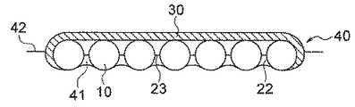
アウターパック40は、一対のアウターシート43a、43bを貼り合せて袋状に形成されており、内部が中空の袋形状である外側袋状部41と、外側袋状部41の周囲に形成された耳状部42とを有する。外側袋状部41の内部には、固液相変化材料10の充填されたインナーパック20及びインナーパック20の片面及び側部を覆う断熱材30が真空封入される。アウターパック40がインナーパック20及び断熱材30を被覆することによって、インナーパック20を破損等から保護し、細長袋状部22の接続部である溶着部23に埃等が溜まるのを防止する。また、アウターパック40がインナーパック20及び断熱材30を被覆する際に真空パックを施すため、通常はアウターパック40とインナーパック20とは密着状態にあるが、万一、外部からピンホールが開いた場合はアウターパック40とインナーパック20との間に空気が入り込み、アウターパック40の真空パックとしての緊張が解けてたるみが生ずる。そのため、このようなアウターパック40の状態から、ピンホールが開いた事実を容易に確認することができ、また、インナーパック20に同様のピンホールが開いている可能性も推測することができるセンサーの役割も果たしている。   The outer pack 40 is formed in a bag shape by bonding a pair of outer sheets 43a and 43b, and is formed around an outer bag-shaped portion 41 having a hollow bag shape inside and around the outer bag-shaped portion 41. And an ear-shaped portion 42. Inside the outer bag-like portion 41, the inner pack 20 filled with the solid-liquid phase change material 10 and the heat insulating material 30 covering one side and side portions of the inner pack 20 are vacuum-sealed. By covering the inner pack 20 and the heat insulating material 30 with the outer pack 40, the inner pack 20 is protected from damage and the like, and dust and the like are prevented from accumulating in the welded portion 23 that is the connecting portion of the elongated bag-like portion 22. In addition, since the outer pack 40 is vacuum-packed when the inner pack 20 and the heat insulating material 30 are covered, the outer pack 40 and the inner pack 20 are usually in close contact with each other, but in the unlikely event a pinhole is opened from the outside. In such a case, air enters between the outer pack 40 and the inner pack 20, and the tension of the outer pack 40 as a vacuum pack is released, resulting in sagging. Therefore, it is possible to easily confirm the fact that the pinhole is opened from the state of the outer pack 40 as described above, and it is possible to estimate the possibility that the same pinhole is opened in the inner pack 20. Also plays a role.

アウターシート43a、43bは、シート状のポリエチレンとアルミニウム箔とシート状のナイロン(登録商標)とを貼り合わせた3層構造を有している。これらの3層は、アウターシート43a、43bをアウターパック40に用いたときに、アウターパック40の内側からアウターパック40の外側へ順に、ポリエチレンとアルミニウム箔とナイロン(登録商標)とが積層されるように配置される。この構造によって、アウターシート43a,43bは柔軟性があり、かつ高い強度を有し、破損しにくくなる。また、アウターシート43a,43bにアルミニウム箔を用いることにより、インナーパック20だけでなく、アウターパック40も水蒸気バリア性を有し、万が一インナーパック20の水蒸気バリアが破れたとしても、このアウターパック40の存在により、全体として固液相変化材料10の機能を保持することができる。また、ポリエチレン及びナイロン(登録商標)は一般的に透明なため、ポリエチレンとナイロン(登録商標)とを貼り合わせただけでは、外からインナーパック及び断熱材が見えてしまい外観が良くないため、アルミニウム箔を用いることでアウターパック40内部を見えないようにする目隠しの役割も果たす。さらに、アルミニウム箔によって熱伝導性が向上して冷却効率又は保温効率が高くなる。また、アウターシート43a、43bの外側表面にナイロン(登録商標)を使用することにより、耐摩耗性が向上する。なお、アウターシート43a、43bは柔軟かつ十分な強度を有し、内部の真空状態を維持できるものであれば、本実施例の材料に特に限定されない。   The outer sheets 43a and 43b have a three-layer structure in which sheet-like polyethylene, aluminum foil, and sheet-like nylon (registered trademark) are bonded together. In these three layers, polyethylene, aluminum foil, and nylon (registered trademark) are laminated in order from the inner side of the outer pack 40 to the outer side of the outer pack 40 when the outer sheets 43 a and 43 b are used in the outer pack 40. Are arranged as follows. With this structure, the outer sheets 43a and 43b are flexible, have high strength, and are not easily damaged. Further, by using aluminum foil for the outer sheets 43a and 43b, not only the inner pack 20 but also the outer pack 40 has a water vapor barrier property. Even if the water vapor barrier of the inner pack 20 is broken, the outer pack 40 As a whole, the function of the solid-liquid phase change material 10 can be maintained. In addition, since polyethylene and nylon (registered trademark) are generally transparent, the inner pack and the heat insulating material can be seen from the outside only by bonding polyethylene and nylon (registered trademark). By using the foil, it also serves as a blindfold so that the inside of the outer pack 40 cannot be seen. Furthermore, the thermal conductivity is improved by the aluminum foil, and the cooling efficiency or the heat retention efficiency is increased. Moreover, wear resistance improves by using nylon (trademark) for the outer surface of outer sheet | seat 43a, 43b. The outer sheets 43a and 43b are not particularly limited to the materials of the present embodiment as long as they are flexible and have sufficient strength and can maintain the internal vacuum state.

次に、本実施の形態の体温調節パックの製造方法について、図面3〜10を参照して説明する。
図3に示すように、2枚のシート21a,21bを重ねて、固液相変化材料10を注入するための開口部26となる1辺(上縁部25b)を残して、他の3辺(両側縁部25a及び下縁部25c)を溶着し、インナーパック20を形成する。本願の実施例では、2枚のシート21a,21bを貼り合わせているが、1枚のシートを中央で二つ折りにして周囲の縁部を貼り合わせてもよい。
Next, the manufacturing method of the body temperature regulation pack of this Embodiment is demonstrated with reference to FIGS.
As shown in FIG. 3, the two sheets 21 a and 21 b are overlapped, and the other three sides are left, leaving one side (upper edge portion 25 b) serving as the opening 26 for injecting the solid-liquid phase change material 10. (Both side edges 25a and lower edge 25c) are welded to form the inner pack 20. In the embodiment of the present application, the two sheets 21a and 21b are bonded together, but one sheet may be folded in the center and the peripheral edges may be bonded together.

次に、向かいあった1対の両側縁部25aの間を等間隔に平行に分割するように、2つのシート21a、21bの必要箇所を溶着し、複数の細長袋状部22を形成する。なお、溶着部23の間隔は本願の実施例では等間隔としているが、適宜間隔を異ならせることで細長袋状部22の各々の大きさを調整してもよい。   Next, the necessary portions of the two sheets 21a and 21b are welded so as to divide the pair of opposite side edge portions 25a in parallel at equal intervals, thereby forming a plurality of elongated bag-like portions 22. In addition, although the space | interval of the welding part 23 is made into the equal space | interval in the Example of this application, you may adjust each magnitude | size of the elongate bag-shaped part 22 by changing a space | interval suitably.

次に、図4に示すように、溶着していない上縁部25bを開口部26として、液相の固液相変化材料10を細長袋状部22の各々に、溶着部23の上端を越えない高さまで注入する。この時、上から見た細長袋状部の22の断面形状は、真円よりもやや紡錘状の円形となる。細長袋状部22の全体としては、略円柱形状となり、溶着した縁部25a、25b、25c及び溶着部23に沿って、細長袋状部22の表面に皺ができる。   Next, as shown in FIG. 4, the upper edge portion 25 b that is not welded is used as the opening 26, and the liquid-phase solid-liquid phase change material 10 is passed to each of the elongated bag-like portions 22 beyond the upper end of the welded portion 23. Inject to no height. At this time, the cross-sectional shape of the elongated bag-like portion 22 as viewed from above is a spindle-like circle slightly more than a perfect circle. As a whole, the elongated bag-like portion 22 has a substantially cylindrical shape, and the surface of the elongated bag-like portion 22 is wrinkled along the welded edges 25 a, 25 b, 25 c and the welded portion 23.

次に、細長袋状部22に充填した固液相変化材料10を冷却して固相になった後、図5に示すように、インナーパック20の内部を真空封入した上で、開口部26となっていた上縁部25bを溶着し、密閉する。この時、上縁部25bに沿った溶着部24は、溶着部23よりもやや上方に離れて設けられる。この後、図6のように上縁部25bを折り返して、各細長袋状部22内に固液相変化材料10を隙間無く充填させるためである。   Next, after the solid-liquid phase change material 10 filled in the elongated bag-like portion 22 is cooled to become a solid phase, the inside of the inner pack 20 is vacuum sealed as shown in FIG. The upper edge portion 25b which has been formed is welded and sealed. At this time, the welded portion 24 along the upper edge portion 25 b is provided slightly above the welded portion 23. Thereafter, the upper edge portion 25b is folded back as shown in FIG. 6 so that the solid-liquid phase change material 10 is filled in the elongated bag-like portions 22 without any gaps.

次に、インナーパック20に封入された固液相変化材料10に熱を与えて、再び液相に戻す。そして、図6及び図7に示すように、周囲の縁部25を全て一側(後述する断熱材30を配置する側)に折り込んで、細長袋状部22の内部に液相の固液相変化材料10が隙間無く充填されている状態にする。縁部を折り込む側は、体温調節パック1が体と接触する側とは反対側である。折り返しが身体側にくると冷却作用効果が弱まるからである。なお、ここでいう「隙間無く充填する」とは、細長袋状部22の容積の100%近く固液相変化材料10が充填されている状態をいい、固液相変化材料10が液相の状態で体温調節パック1を縦方向に配置した場合でも、細長袋状部22は変形しなくなる。   Next, heat is applied to the solid-liquid phase change material 10 enclosed in the inner pack 20 to return to the liquid phase again. Then, as shown in FIGS. 6 and 7, all the peripheral edges 25 are folded to one side (the side on which a heat insulating material 30 to be described later is disposed), and a liquid-phase solid-liquid phase is formed inside the elongated bag-like portion 22. The change material 10 is filled with no gaps. The side where the edge is folded is the side opposite to the side where the body temperature regulation pack 1 contacts the body. This is because the cooling effect is weakened when the turn is on the body side. Here, “fill without gap” means a state in which the solid-liquid phase change material 10 is filled with nearly 100% of the volume of the elongated bag-like portion 22, and the solid-liquid phase change material 10 is in the liquid phase. Even when the body temperature regulation pack 1 is arranged in the vertical direction in the state, the elongated bag-like portion 22 does not deform.

次に、図8に示すように、インナーパック20の片面(体温調節パック1が体と接触する面と反対の面)において固液相変化材料10が充填されている部分全体を覆うように、断熱材30を取り付ける。   Next, as shown in FIG. 8, so as to cover the entire portion filled with the solid-liquid phase change material 10 on one side of the inner pack 20 (the surface opposite to the surface where the body temperature regulation pack 1 contacts the body) A heat insulating material 30 is attached.

次に、図9に示すように2枚のアウターシート43a及び43bから形成されるアウターパック40の外側袋状部41の内部に、断熱材30を取り付けたインナーパック20を入れて、図10に示すように真空封入して、完成する。なお、アウターシート43a及び43bの間にインナーパック20を挟みこんだ後に、アウターシート43a、43bの周囲を貼り合わせてアウターパック40を形成してから、真空封入してもよい。また、本実施形態では、同形状及び同素材である2枚のシート43a、43bを用いているが、1枚のシートを2つ折りにして1対にして、インナーパック20を挟み込んでもよい。   Next, as shown in FIG. 9, the inner pack 20 with the heat insulating material 30 attached is placed inside the outer bag-like portion 41 of the outer pack 40 formed from the two outer sheets 43a and 43b. Complete with vacuum encapsulation as shown. Alternatively, after the inner pack 20 is sandwiched between the outer sheets 43a and 43b, the outer sheets 43a and 43b may be bonded together to form the outer pack 40, and then vacuum sealed. In the present embodiment, the two sheets 43a and 43b having the same shape and the same material are used. However, the inner pack 20 may be sandwiched by folding one sheet into two to make a pair.

このようにして形成された体温調節パック1は、平行方向に複数の細長袋状部22が、柔軟性のある溶着部23を介して並列しているため、固液相変化材料10が固相になった場合でも、図11に示すように、溶着部23を節として体温調節パック1を体の形に沿って曲げることが可能となり、体温調節パック1の人体への密着性がより高くなる。従って、冷却材または保温材の固液相変化材料10を100%とすることによる高い熱吸収能力または放熱能力と、人体への追随性とを両立することができる。さらに、円柱形状の細長袋状部を横方向に並列したことにより、全体として表面に凹凸形状をもつ略板形状となっている。そのため、複数の体温調節パック1を保管するときは、図12に示すように安定して重ねて保管することができ、余計なスペースをとらない。   In the body temperature regulation pack 1 formed in this way, since the plurality of elongated bag-like portions 22 are arranged in parallel via the flexible welded portion 23, the solid-liquid phase change material 10 is in a solid phase. Even in this case, as shown in FIG. 11, it becomes possible to bend the body temperature regulation pack 1 along the shape of the body with the welded portion 23 as a node, and the adhesion of the body temperature regulation pack 1 to the human body becomes higher. . Therefore, it is possible to achieve both high heat absorption capability or heat dissipation capability by setting the solid-liquid phase change material 10 of the coolant or the heat retaining material to 100% and the followability to the human body. Furthermore, the cylindrical elongated bag-like portions are arranged in parallel in the lateral direction, so that the entire surface has a substantially plate shape with an uneven shape on the surface. Therefore, when storing a plurality of body temperature regulation packs 1, as shown in FIG. 12, it can be stably stacked and stored, and no extra space is taken up.

(実施形態2)
次に、後述するパックホルダー2に取り付けて使用する、別の実施形態に係る体温調節パック100について、図13〜21を参照して説明する。体温調節パック100は、外形としては、図1に示す体温調節パック1と同じ形態であり、全体は略板状の矩形に形成されており、平行に配列された複数の袋体Tを備えている。
図20に示すように、体温調整パック100は、固液相変化材料10が充填された複数の細長袋体322から構成され、細長袋体322同士を並列に配置させる細長袋体整列部材27と、平行方向に並列する複数の細長袋体322の片側の面を覆う断熱材30と、細長袋体322、細長袋体整列部材27及び断熱材30を全体的に被覆するアウターパック40とを有している。また、体温調節パック100の表面は、アウターパック40内部の細長袋体の形状に沿った凹凸形状を有している。なお、本実施例では、体温調整パック100の形状は、全体として略板状の矩形に形成されているが、これに限定されず、他の形でもよい。
(Embodiment 2)
Next, a body temperature regulation pack 100 according to another embodiment that is used by being attached to a pack holder 2 described later will be described with reference to FIGS. The body temperature regulation pack 100 has the same form as the body temperature regulation pack 1 shown in FIG. 1 as an outer shape, and is formed in a substantially plate-like rectangle as a whole, and includes a plurality of bag bodies T arranged in parallel. Yes.
As shown in FIG. 20, the body temperature adjustment pack 100 includes a plurality of elongated bag bodies 322 filled with the solid-liquid phase change material 10, and the elongated bag body alignment member 27 that arranges the elongated bag bodies 322 in parallel with each other. A heat insulating material 30 that covers one surface of the plurality of elongate bag bodies 322 arranged in parallel, and an outer pack 40 that covers the elongate bag body 322, the elongate bag body alignment member 27, and the heat insulating material 30 as a whole. is doing. Further, the surface of the body temperature regulation pack 100 has a concavo-convex shape along the shape of the elongated bag body inside the outer pack 40. In the present embodiment, the shape of the body temperature adjustment pack 100 is formed in a substantially plate-like rectangle as a whole, but is not limited to this, and may have other shapes.

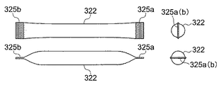
図13〜15に示すように、細長袋体322の各々は、フィルムで形成され、細長い円筒形状をしており、両端は溶着されている。フィルムは、実施例1のインナーシート21と同様、柔軟性と強度を確保するために、シート状のポリエチレンとアルミニウム箔とシート状のナイロン(登録商標)とを張り合わせた3層構造であることが好ましい。但し、細長袋体322のフィルムは、柔軟かつ十分な強度を有し、内部に封入された固液相変化材料10が漏出しないものであれば、本実施例の材料に特に限定されない。また、細長袋体322の長さ及び太さは、用途や取り付ける部位に応じて適宜変更することができる。   As shown in FIGS. 13 to 15, each of the elongated bag bodies 322 is formed of a film, has an elongated cylindrical shape, and both ends are welded. Like the inner sheet 21 of Example 1, the film has a three-layer structure in which sheet-like polyethylene, aluminum foil, and sheet-like nylon (registered trademark) are bonded together in order to ensure flexibility and strength. preferable. However, the film of the elongated bag body 322 is not particularly limited to the material of this embodiment as long as it has a flexible and sufficient strength and the solid-liquid phase change material 10 enclosed therein does not leak. In addition, the length and thickness of the elongated bag body 322 can be changed as appropriate according to the application and the part to be attached.

本実施例のように、複数の独立した細長袋体322を用いることにより、実施例1のように1対のインナーシート21a及び21bから複数の細長袋状部22を形成したときよりも、各々の細長袋体322のフィルムへのストレスが小さくなり、耐久性能が増す。すなわち、図11のように体温調節パック100が湾曲したときに、実施例1ではインナーシート21が湾曲とともに引っ張り力を受けるが、本実施例のように細長袋体322が各々独立していれば、身体部位に合わせて湾曲させた場合でも余分な負荷は加わらない。従って、フィルムが破損し体温調節パック100の機能が喪失する危険性は最小限となる。即ち、フィルムの水蒸気バリア性を担保すべきアルミ層破損の危険性が最小限となる。また、万一、外部から針状のものが刺さった場合であっても、ピンホールがあいて破損した細長袋体322の1つが機能を喪失するだけで、他の細長袋体322には影響を及ぼさず、体温調節パック100全体としての機能は失われない。すなわち、体温調節パック100が複数の独立した細長袋体322を有することにより、機能喪失のリスクが最小化される。また、壊れた細長袋体322を交換するだけで、体温調節パック100の機能を再生することができるため、修理が容易かつ低廉である。またさらに、長さや太さの違う複数種類の細長袋体322を事前に製造しておけば、体温調節パック100の製造時に適宜組み合わせることによって、より適正な体温調整が可能となる。   By using a plurality of independent elongated bag bodies 322 as in this embodiment, each of the plurality of elongated bag-like portions 22 is formed from a pair of inner sheets 21a and 21b as in the first embodiment. The stress on the film of the elongated bag body 322 is reduced, and the durability performance is increased. That is, when the body temperature regulation pack 100 is bent as shown in FIG. 11, the inner sheet 21 receives a tensile force along with the bending in the first embodiment. However, if the elongated bag bodies 322 are independent from each other as in the present embodiment. No extra load is applied even when bent according to the body part. Therefore, the risk of damaging the film and losing the function of the body temperature control pack 100 is minimized. That is, the risk of damage to the aluminum layer that should ensure the water vapor barrier property of the film is minimized. Also, even if a needle-like object is stuck from the outside, only one of the elongated bag bodies 322 damaged by pinholes loses its function, and the other elongated bag bodies 322 are affected. The function of the body temperature regulation pack 100 as a whole is not lost. That is, since the body temperature regulation pack 100 has a plurality of independent elongated bag bodies 322, the risk of loss of function is minimized. Further, since the function of the body temperature regulation pack 100 can be regenerated by simply replacing the broken elongated bag body 322, the repair is easy and inexpensive. Furthermore, if a plurality of types of elongated bag bodies 322 having different lengths and thicknesses are manufactured in advance, more appropriate body temperature adjustment is possible by appropriately combining them at the time of manufacturing the body temperature regulation pack 100.

細長袋体322の内部には、固液相変化材料10が細長袋体322の内容量いっぱいに隙間無く充填されており、細長袋体322は細長い円柱形状となっている。このため、固液相変化材料10が液相の状態で体温調節パック100を縦方向に配置した場合でも、細長袋体322に撓みが生じる余裕がないため、細長袋体322は変形することがない。また、平行方向に各々独立した複数の細長袋体322が配列されているため、固液相変化材料10が固相になった場合でも、体温調節パック100を体の形に沿って曲げることが可能となり、体温調節パック100の人体への密着性がより高くなる。さらに、円柱形状の細長袋体322を横方向に並列したことにより、全体として表面に凹凸形状をもつ略板形状となっている。そのため、複数の体温調節パック100を保管するときは、安定して重ねて保管することができ、余計なスペースをとらない。なお、ここで「隙間なく充填する」とは、実施形態1と同様で、細長袋体322の容積の100%近く固液相変化材料10が充填されている状態をいい、固液相変化材料10が液相の状態で体温調節パック100を縦方向に配置した場合でも、細長袋体322は変形しなくなる。   The elongate bag body 322 is filled with the solid-liquid phase change material 10 to fill the inner volume of the elongate bag body 322 without any gaps, and the elongate bag body 322 has an elongated cylindrical shape. For this reason, even when the body temperature regulation pack 100 is arranged in the vertical direction while the solid-liquid phase change material 10 is in the liquid phase, the elongated bag body 322 can be deformed because there is no room for bending in the elongated bag body 322. Absent. In addition, since a plurality of independent elongate bag bodies 322 are arranged in the parallel direction, even when the solid-liquid phase change material 10 becomes a solid phase, the body temperature regulation pack 100 can be bent along the shape of the body. It becomes possible, and the adhesiveness of the body temperature regulation pack 100 to the human body becomes higher. Furthermore, the cylindrical elongated bag bodies 322 are juxtaposed in the horizontal direction, thereby forming a substantially plate shape having a concavo-convex shape on the entire surface. Therefore, when storing a plurality of body temperature regulation packs 100, they can be stably stacked and stored, and no extra space is taken up. Here, “fill without gaps” means the state in which the solid-liquid phase change material 10 is filled nearly 100% of the volume of the elongated bag body 322, as in the first embodiment, and the solid-liquid phase change material. Even when the body temperature regulation pack 100 is arranged in the vertical direction while 10 is in a liquid phase, the elongated bag body 322 is not deformed.

また、実施例1と同様に、体温調節パック100は、固液相変化材料10の量を増やしても変形する心配が無いため、図22に示すように、細長袋体322は適宜直径を変えることにより、体の部位や必要な冷却機能保持時間又は保温機能保持時間に応じて、固液相変化材料10の量を調整することができる。   Further, as in the first embodiment, the body temperature regulation pack 100 has no fear of being deformed even when the amount of the solid-liquid phase change material 10 is increased. Therefore, as shown in FIG. 22, the elongated bag body 322 is appropriately changed in diameter. Thus, the amount of the solid-liquid phase change material 10 can be adjusted according to the body part, the required cooling function holding time or the heat holding function holding time.

細長袋体322を載置し整列させるための細長袋体整列部材27は、図16及び図17に示すように、上から見ると細長袋体322のほぼ全長にわたる長方形状をしている。また、横から見ると、細長袋体322の各々が載置される窪み部28と、隣り合う細長袋体322どうしの間に食いこみ、各々の細長袋体322の位置を等間隔に配置する突出部29とを有する。さらに、細長袋体整列部材27は、ボール紙等の柔軟な素材からできており、身体部位に沿って自在に湾曲することができるようになっている。また、細長袋体整列部材27の形状は、本実施例に限定されず、細片状のものを横置きにして1つ又は複数個使用するものであってもよい。   As shown in FIGS. 16 and 17, the elongated bag body alignment member 27 for placing and aligning the elongated bag body 322 has a rectangular shape covering almost the entire length of the elongated bag body 322 as viewed from above. Further, when viewed from the side, the elongated bag body 322 is bitten between the recess 28 where the elongated bag body 322 is placed and the adjacent elongated bag bodies 322, and the positions of the elongated bag bodies 322 are arranged at equal intervals. And a protrusion 29. Further, the elongated bag body alignment member 27 is made of a flexible material such as cardboard, and can be freely bent along the body part. Further, the shape of the elongated bag body alignment member 27 is not limited to the present embodiment, and one or a plurality of strip-shaped members may be used by placing them horizontally.

図16に示すように、細長袋体整列部材27に細長袋体322を載置することによって、細長袋体322どうしの位置が等間隔を保つようになり、その結果、互いの細長袋体322がぶつかって傷がつくリスクがなくなる。また、細長袋体整列部材27は、柔軟性をもつ素材によってつくられているため、体温調整パック100が身体部位への密着性を保つように湾曲することができる。   As shown in FIG. 16, by placing the elongated bag bodies 322 on the elongated bag body alignment member 27, the positions of the elongated bag bodies 322 are kept at equal intervals, and as a result, the elongated bag bodies 322 are mutually arranged. There is no risk of hitting and scratching. Moreover, since the elongate bag body alignment member 27 is made of a flexible material, the body temperature adjustment pack 100 can be bent so as to maintain adhesion to the body part.

固液相変化材料10、断熱材30及びアウターパック40の特性については、実施形態1と同様なので、省略する。   Since the characteristics of the solid-liquid phase change material 10, the heat insulating material 30, and the outer pack 40 are the same as those in the first embodiment, a description thereof will be omitted.

次に本実施の形態の体温調節パック100の製造方法について、図13〜21を参照して説明する。
まずは、図13に示すようにフィルムで円筒形の細長袋体322を作る。一方の端部は固液相変化材料の注入口326として開口し、反対の端部は溶着する。細長袋体322の直径・長さは用途によって適宜変更することができる。
Next, the manufacturing method of the body temperature regulation pack 100 of this Embodiment is demonstrated with reference to FIGS.
First, as shown in FIG. 13, a cylindrical elongated bag 322 is made of a film. One end opens as a solid-liquid phase change material inlet 326 and the opposite end welds. The diameter and length of the elongated bag body 322 can be appropriately changed depending on the application.

次に、図14に示すように、真空下で注入口326から細長袋体322内部に液相の固液相変化材料10を充填した後、注入口326を溶着して密封し、細長袋体322内部に固液相変化材料10が隙間なく充填されている状態にする。このようにして真空封入すれば、液相の固液相変化材料10を充填した後で、冷却して固相にした状態で真空封入してから、再び液相に戻す必要がない分、製造工程が短縮化され、大量生産が可能となる。なお、この真空封入作業には、既知の自動真空包装機を用いることができるが、ここでは当該包装機の説明は省略する。   Next, as shown in FIG. 14, after filling the elongated solid bag body 322 with the liquid-solid-liquid phase change material 10 from the injection port 326 under vacuum, the injection port 326 is welded and sealed, and the elongated bag body is obtained. 322 is filled with the solid-liquid phase change material 10 without a gap. If the vacuum sealing is performed in this manner, it is not necessary to fill the liquid-phase solid-liquid phase change material 10 and then vacuum-enclose it in a solid state after cooling, and then return to the liquid phase again. The process is shortened and mass production becomes possible. In addition, although a known automatic vacuum packaging machine can be used for this vacuum sealing operation | work, description of the said packaging machine is abbreviate | omitted here.

次に、図15に示すように、両端の溶着部325a、325bを細長袋体の一側(後述する細長袋体整列部材27及び断熱材30を配置する側)に折り曲げる。溶着部325a、325bを折り込む側は、体温調節パック100が体と接触する側とは反対側である。折り返し部分が身体側にくると冷却作用効果が弱まるからである。   Next, as shown in FIG. 15, the welded portions 325 a and 325 b at both ends are bent to one side of the elongated bag body (the side on which the elongated bag body alignment member 27 and the heat insulating material 30 described later are disposed). The side where the welded portions 325a and 325b are folded is the side opposite to the side where the body temperature regulation pack 100 contacts the body. This is because the cooling effect is weakened when the folded portion comes to the body side.

さらに、上記の製造方法によって作られた複数の細長袋体322の各々を細長袋体整列部材27の上に平行方向に等間隔に並列させ(図16参照)、載置する。細長袋体整列部材を取り付ける側は、溶着部325a、325bを折り込んでいる側、すなわち体温調節パック100が体と接触する側と反対の側である。外部の熱が体温調節パック100に伝わるのを防ぐためである。   Further, each of the plurality of elongate bag bodies 322 produced by the above manufacturing method is placed on the elongate bag body alignment member 27 in parallel with equal intervals (see FIG. 16) and placed. The side to which the elongated bag body alignment member is attached is the side where the welded portions 325a and 325b are folded, that is, the side opposite to the side where the body temperature regulation pack 100 contacts the body. This is to prevent external heat from being transmitted to the body temperature regulation pack 100.

次に、図18に示すように、体温調節パック100が体と接触する面と反対側の面に、細長袋体整列部材27ごと複数の細長袋体322全体を覆うようにして、断熱材30を取り付ける。この時、細長袋体整列部材27の取り付け側が断熱材30で覆われるようにする。断熱材30のない側、すなわち身体に接触する側に細長袋体整列部材27があると冷却効率あるいは保温効率が悪くなるからである。   Next, as shown in FIG. 18, the heat insulating material 30 is formed so that the entire body of the plurality of elongate bag bodies 322 is covered with the elongate bag body alignment member 27 on the surface opposite to the surface where the body temperature regulation pack 100 contacts the body. Install. At this time, the attachment side of the elongated bag alignment member 27 is covered with the heat insulating material 30. This is because if the elongated bag body alignment member 27 is on the side without the heat insulating material 30, that is, the side in contact with the body, the cooling efficiency or the heat retention efficiency is deteriorated.

また、断熱材には、図21に示すような上面が開放された箱型の断熱材30´を使用してもよい。この断熱材30´を使用する場合、断熱材30´の内側に細長袋体整列部材27を入れ、その上に細長袋体322を載置して整列させる。これによって、より簡単に細長袋体322に細長袋体整列部材27と断熱材30´とを取り付けることができる。また、このように断熱材30´を取り付けた結果、複数の細長袋体322は全体として、身体に接しない一側と側部の4面を断熱材30´で覆われることができ、断熱効果が高まる。なお、断熱材30´は、両端に立上り部を有する長方形状の2枚の断熱板30´a、30´bを箱型に組んで形成する。その結果、底面の断熱材が二重になりより高い断熱性能を得ることができる。但し、箱型の断熱材30´の形成方法はこれに限られず、1枚の断熱板を加工して形成してもよい。また、この断熱板30´a、30´bは既存の気泡緩衝材の両面にアルミ箔のシートを貼り付けた板状の断熱材でできているが、素材はこれに限られない。   Further, as the heat insulating material, a box-shaped heat insulating material 30 ′ having an open upper surface as shown in FIG. 21 may be used. When this heat insulating material 30 ′ is used, the elongated bag body alignment member 27 is placed inside the heat insulating material 30 ′, and the elongated bag body 322 is placed thereon and aligned. Thereby, the elongated bag body alignment member 27 and the heat insulating material 30 ′ can be attached to the elongated bag body 322 more easily. Moreover, as a result of attaching the heat insulating material 30 'in this way, the plurality of elongated bag bodies 322 can be covered with the heat insulating material 30' on one side and the side part not contacting the body as a whole. Will increase. The heat insulating material 30 ′ is formed by assembling two rectangular heat insulating plates 30 ′ a and 30 ′ b having rising portions at both ends into a box shape. As a result, the heat insulating material on the bottom surface becomes double, and higher heat insulating performance can be obtained. However, the method of forming the box-shaped heat insulating material 30 'is not limited to this, and it may be formed by processing one heat insulating plate. Moreover, although these heat insulation board 30'a and 30'b are made from the plate-shaped heat insulating material which stuck the sheet | seat of the aluminum foil on both surfaces of the existing bubble buffer material, a raw material is not restricted to this.

次に、図19に示すように2枚のアウターシート43a及び43bから形成されるアウターパック40の外側袋状部41の内部に、細長袋体整列部材27及び断熱材30(30´)を取り付けた細長袋体322を入れて、図20に示すように真空封入して、完成する。なお、アウターシート43a及び43bの間に細長袋体322を挟みこんだ後に、アウターシート43a、43bの周囲を貼り合わせてアウターパック40を形成してから、真空封入してもよい。また、本実施形態では、同形状及び同素材である2枚のシート43a、43bを用いているが、1枚のシートを2つ折りにして1対にして、細長袋体322を挟み込んでもよい。   Next, as shown in FIG. 19, the elongated bag body alignment member 27 and the heat insulating material 30 (30 ′) are attached to the inside of the outer bag-like portion 41 of the outer pack 40 formed from the two outer sheets 43a and 43b. The long and slender bag body 322 is put and vacuum sealed as shown in FIG. Alternatively, after the elongated bag body 322 is sandwiched between the outer sheets 43a and 43b, the outer sheets 43a and 43b may be bonded together to form the outer pack 40, and then vacuum sealed. In the present embodiment, the two sheets 43a and 43b having the same shape and the same material are used. However, the elongated bag body 322 may be sandwiched by folding one sheet into a pair.

このようにして形成された体温調節パック100は、内部に各々独立した複数の細長袋体322が平行方向に並列しているため、固液相変化材料10が固相になった場合でも、体温調節パック100を体の形に沿って曲げることが可能となり、体温調節パック100の人体への密着性がより高くなる。従って、冷却材または保温材の固液相変化材料を100%とすることによる高い熱吸収能力または放熱能力と、人体への追随性を両立することができる。さらに、円柱形状の細長袋体322を横方向に並列したことにより、全体として表面に凹凸形状をもつ略板形状となっている。そのため、複数の体温調節パック100を保管するときは、図12に示すように安定して重ねて保管することができ、余計なスペースをとらない。
なお、本実施例では、体温調節パック100を構成する細長袋体322の本数は7本となっているが、体温調節が必要とされる身体部位を被覆することができるのであれば、本数はこれに限定されない。また、細長袋体322の太さ及び長さは、用途に応じて自由に設定することができる。
Since the body temperature regulation pack 100 formed in this way has a plurality of independent elongated bag bodies 322 arranged in parallel in the parallel direction, even when the solid-liquid phase change material 10 becomes a solid phase, the body temperature The adjustment pack 100 can be bent along the shape of the body, and the adhesion of the body temperature adjustment pack 100 to the human body becomes higher. Therefore, it is possible to achieve both high heat absorption capability or heat dissipation capability by setting the solid-liquid phase change material of the coolant or the heat retaining material to 100% and the followability to the human body. Furthermore, the cylindrical elongated bag bodies 322 are juxtaposed in the horizontal direction, thereby forming a substantially plate shape having a concavo-convex shape on the entire surface. Therefore, when storing a plurality of body temperature regulation packs 100, they can be stably stacked and stored as shown in FIG. 12, and no extra space is taken up.
In the present embodiment, the number of the elongated bag bodies 322 constituting the body temperature regulation pack 100 is seven. However, if the body part requiring body temperature regulation can be covered, the number is as follows. It is not limited to this. Moreover, the thickness and length of the elongate bag body 322 can be freely set according to a use.

[メッシュ袋]
次に、前述の体温調節パック1または100を挿入して後述する胴体パックホルダー80(図28参照)に取り付けるための専用のメッシュ製のメッシュ袋51について、図26及び図27を参照して、説明するが、体温調節パック1及び100は外側の形態が同一であるため、便宜上、体温調節パック1について説明をする。なお、体温調節パック1のアウターパック40は前述したようにフィルム製のため、表面のナイロン(登録商標)に直接面ファスナーを取り付けることができない。また、ナイロン(登録商標)に直接、面ファスナー97bを取り付けようとする場合は、接着剤を用いるしかなく、最も効率が高いのは溶剤による溶着であるが、その分アウターパック40のフィルム強度が低下する。従って、以上の点に鑑みて、メッシュ袋51に、図26のように体温調節パック1を挿入して、体温調節パック1を胴体パックホルダー80に対して着脱自在に取り付けられるようにしてある。
[Mesh bag]
Next, a mesh bag 51 made of a special mesh for inserting the body temperature regulation pack 1 or 100 and attaching it to a body pack holder 80 (see FIG. 28) described later, with reference to FIGS. 26 and 27, As will be described, since the body temperature regulation packs 1 and 100 have the same outer form, the body temperature regulation pack 1 will be described for convenience. Since the outer pack 40 of the body temperature regulation pack 1 is made of a film as described above, a hook-and-loop fastener cannot be directly attached to the surface nylon (registered trademark). Further, when attaching the hook-and-loop fastener 97b directly to nylon (registered trademark), it is only possible to use an adhesive, and the most efficient is welding with a solvent, but the film strength of the outer pack 40 is correspondingly increased. descend. Therefore, in view of the above points, the body temperature regulation pack 1 is inserted into the mesh bag 51 as shown in FIG. 26 so that the body temperature regulation pack 1 can be detachably attached to the body pack holder 80.

図26及び図27に示すように、着用者の胸部に配置されるメッシュ袋51は、矩形の形状をしており、後述する胴体パックホルダー80の面ファスナー97a(図31参照)に着脱自在に取り付けるために、胴体パックホルダー80に取り付ける側の面に面ファスナー97bが設けられている。本実施例では、メッシュ袋51の形状は矩形であるが、装着する体の部位や挿入する体温調節パック1の形状に応じて、矩形以外の形状、例えば楕円形などにしてもよい。   As shown in FIGS. 26 and 27, the mesh bag 51 arranged on the chest of the wearer has a rectangular shape and is detachable from a hook-and-loop fastener 97a (see FIG. 31) of the body pack holder 80 described later. For attachment, a hook-and-loop fastener 97b is provided on the surface to be attached to the fuselage pack holder 80. In the present embodiment, the mesh bag 51 has a rectangular shape. However, the mesh bag 51 may have a shape other than the rectangular shape, for example, an oval shape, depending on the body part to be attached and the shape of the body temperature regulation pack 1 to be inserted.

体温調節パック1を胴体パックホルダー80に着脱自在に取り付けられるように、図26に示すように、体温調節パック1をメッシュ袋51に挿入し、面ファスナーなどの既知の手段で挿入口を開閉自在に塞ぐ。体温調節パック1はメッシュ袋51から取り出し自在なので、用途等に応じて体温調節パック1の種類(固液相変化材料の封入量が違うもの等)を交換することができる。また、メッシュ袋51が汚れても、体温調節パック1だけ取り出して洗濯することができる。なお、本実施例では、図27(a)に示すようにメッシュ袋51内には、体温調節パック1が一個だけ封入されているが、メッシュ袋51の容量や体温調節パック1の大きさに応じて二個以上封入してもよい。さらに、本実施例では、挿入口は開閉自在としたが、縫い付ける等の手段で閉じこんでしまってもよい。   As shown in FIG. 26, the body temperature regulation pack 1 is inserted into the mesh bag 51 so that the body temperature regulation pack 1 can be detachably attached to the body pack holder 80, and the insertion port can be opened and closed by a known means such as a hook-and-loop fastener. Close up. Since the body temperature regulation pack 1 can be taken out from the mesh bag 51, the type of body temperature regulation pack 1 (such as a different amount of solid-liquid phase change material) can be exchanged depending on the application. Even if the mesh bag 51 is dirty, only the body temperature regulation pack 1 can be taken out and washed. In the present embodiment, only one body temperature regulation pack 1 is enclosed in the mesh bag 51 as shown in FIG. 27A. However, the size of the mesh bag 51 and the size of the body temperature regulation pack 1 are the same. Two or more may be enclosed depending on the case. Furthermore, in this embodiment, the insertion slot is freely openable / closable, but may be closed by means such as sewing.

面ファスナー97bは図27(b)に示すように、細長片に形成されており、メッシュ袋51の一対の端部に平行に設けられる。なお、面ファスナーの本数は本実施例に限られず、体温調節パック1を胴体パックホルダー80に保持することができる限り、1本であっても、3本以上並べてもよく、さらに、メッシュ袋の一側の面を全体的に面ファスナーとすることや、メッシュ袋の素材自体を面ファスナーとすることもできる。また、後述する胴体パックホルダー80側の面ファスナー97aは、他の衣服に付着しないように、ループ状の面ファスナーにしてあるので、メッシュ袋51の面ファスナーはフック状とする。但し、これに限定されることなく、メッシュ袋51の面ファスナー97bをループ状、胴体パックホルダー80側の面ファスナー97aをフック状としてもよい。   As shown in FIG. 27B, the hook-and-loop fastener 97 b is formed in an elongated piece, and is provided in parallel with the pair of end portions of the mesh bag 51. The number of hook-and-loop fasteners is not limited to the present embodiment, and as long as the body temperature regulation pack 1 can be held in the body pack holder 80, the number of hook-and-loop fasteners may be one or three or more. The surface on one side can be used as a surface fastener as a whole, or the mesh bag material itself can be used as a surface fastener. Further, since the surface fastener 97a on the body pack holder 80 described later is a loop surface fastener so as not to adhere to other clothes, the surface fastener of the mesh bag 51 is formed in a hook shape. However, without being limited thereto, the hook-and-loop fastener 97b of the mesh bag 51 may be formed in a loop shape, and the hook-and-loop fastener 97a on the body pack holder 80 side may be formed in a hook shape.

メッシュ袋51の素材はメッシュ状布帛である。これによって、身体から放出された熱をより効率よく吸収することができる。また、冷却用の体温調節パック1を氷水につけて固相に戻す際には、メッシュ袋51がメッシュ素材であれば、いちいち体温調節パック1を取り出さずにメッシュ袋51ごと氷水に浸して冷却することができる。   The material of the mesh bag 51 is a mesh fabric. Thereby, the heat released from the body can be absorbed more efficiently. Further, when the body temperature regulation pack 1 for cooling is put on ice water and returned to the solid phase, if the mesh bag 51 is a mesh material, the body temperature regulation pack 1 is immersed in ice water and cooled without taking out the body temperature regulation pack 1 one by one. be able to.

以上、胸部に配置されるメッシュ袋51について説明してきたが、背中に配置されるメッシュ袋61及び脇下に配置されるメッシュ袋66も同様に構成されている(図30参照)。   The mesh bag 51 disposed on the chest has been described above, but the mesh bag 61 disposed on the back and the mesh bag 66 disposed on the armpit are also configured similarly (see FIG. 30).

[パックホルダー]
前述の体温調節パック1を身体に装着するためのパックホルダー2について、図28〜35を参照して説明する。パックホルダー2は、体温調節パック1を胴体に装着するための胴体パックホルダー80、体温調節パック1を首周りに装着するための襟部パックホルダー70から構成される。また、体温調節パック1を脚部に装着するための脚部パックホルダー90も有する。
[Pack holder]
A pack holder 2 for mounting the body temperature regulation pack 1 on the body will be described with reference to FIGS. The pack holder 2 includes a body pack holder 80 for mounting the body temperature regulation pack 1 on the body and a collar pack holder 70 for mounting the body temperature regulation pack 1 around the neck. Moreover, it also has a leg pack holder 90 for mounting the body temperature regulation pack 1 on the leg.

〈胴体パックホルダー〉
まず、体温調節パック1を主に胴体に装着するための専用の胴体パックホルダー80について、図28〜33を参照して説明する。
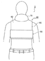
図28〜30は、それぞれ、本発明の胴体パックホルダー80の着用状態を示す正面図、背面図及び側面図である。なお、図28〜30には胴体に取り付ける胴体パックホルダー80の他に、首周りに取り付ける後述の襟部パックホルダー70(図34参照)の着用状態も示されている。図31及び図32は、本発明の胴体パックホルダー80を各部分に分解したもので、それぞれ前面部及び後面部の表側及び裏側を示す図である。なお、ここで、表面とは、胴体パックホルダー80を着用したときに身体に接触する側と反対側の面をいい、裏面とは身体に接触する側の面をいう。以下の説明においても同様とする。
<Torso pack holder>
First, a dedicated torso pack holder 80 for mounting the body temperature regulation pack 1 mainly on the torso will be described with reference to FIGS.
28 to 30 are a front view, a rear view, and a side view, respectively, showing a wearing state of the body pack holder 80 of the present invention. 28 to 30 also show a worn state of a later-described collar pack holder 70 (see FIG. 34) to be attached around the neck in addition to the body pack holder 80 attached to the body. FIGS. 31 and 32 are exploded views of the fuselage pack holder 80 of the present invention, showing the front side and the back side of the front part and the rear part, respectively. Here, the front surface refers to a surface opposite to the side that contacts the body when the torso pack holder 80 is worn, and the back surface refers to a surface that contacts the body. The same applies to the following description.

最初に、胴体パックホルダー80の全体構成について説明する。図28〜30に示すように、胴体パックホルダー80は、胸部を被覆する前面部50と、肩から背中までを被覆する後面部60とで構成されている。後面部60の表面下部には、脇下を被覆する帯部65が縫合され一体になっている。後面部60は両肩部分に肩掛け部64を有しており、前面部50は、肩掛け部64を介して、後面部60と着脱自在に接続される。前面部50と後面部60とが着脱自在に取り付けられるように各部に分離していることにより、着用者の体格や体温調節パック1の配置数によって、胴体パックホルダー80を調整することができる。なお、本実施例では、胴体パックホルダー80は胸部と背中の上半分のみを被覆しているが、これに限られず腹部や背中の下半分も被覆できるように長さを変えてもよい。   First, the overall configuration of the fuselage pack holder 80 will be described. As shown in FIGS. 28 to 30, the torso pack holder 80 includes a front surface portion 50 that covers the chest and a rear surface portion 60 that covers from the shoulder to the back. A band portion 65 that covers the armpit is stitched to and integrated with the lower surface portion of the rear surface portion 60. The rear surface portion 60 has shoulder portions 64 on both shoulder portions, and the front surface portion 50 is detachably connected to the rear surface portion 60 via the shoulder portions 64. By separating the front part 50 and the rear part 60 so as to be detachable, the body pack holder 80 can be adjusted according to the wearer's physique and the number of body temperature adjustment packs 1 arranged. In this embodiment, the torso pack holder 80 covers only the upper half of the chest and the back, but the length is not limited to this, and the length may be changed so that the abdomen and the lower half of the back can be covered.

胴体パックホルダー80の主な素材は、前面部50及び後面部60ともにメッシュ状布帛である。素材をメッシュ状布帛にすることにより、胴体パックホルダー80全体を軽量化し、着用者の身体から放出された熱が胴体パックホルダー80内にこもらないようにすることができる。また、冷却用の固液相変化材料10を用いる場合、胴体パックホルダー80が水に濡らしても乾きやすいメッシュ状素材でできていることにより、胴体パックホルダー80ごと氷水に浸けて冷却することができ、短時間で容易に液相になった固液相変化材料10を固相に戻すことができる。さらに、メッシュ状布帛を透して、胴体パックホルダー80全体に水や空気が対流しやすい状態となるので、胴体パックホルダー80ごと水に浸けて冷やしたり、冷蔵庫で冷却する際には、固液相変化材料10の機能回復がより早くなる。   The main material of the fuselage pack holder 80 is a mesh fabric for both the front surface portion 50 and the rear surface portion 60. By making the material a mesh fabric, the entire body pack holder 80 can be reduced in weight, and heat released from the wearer's body can be prevented from being trapped in the body pack holder 80. When the solid-liquid phase change material 10 for cooling is used, the fuselage pack holder 80 is made of a mesh-like material that can be easily dried even when wet, so that the fuselage pack holder 80 can be cooled by being immersed in ice water. It is possible to return the solid-liquid phase change material 10 that has become a liquid phase easily in a short time to the solid phase. Furthermore, since the mesh fabric is permeated so that water and air are easily convected through the entire fuselage pack holder 80, when the whole fuselage pack holder 80 is soaked in water or cooled in a refrigerator, The function recovery of the phase change material 10 becomes faster.

前面部50は、図31に示すように、着用者の胸部を覆う体温調節パック保持部52からなり、体温調節パック保持部52の裏面にはメッシュ袋51が装着される。体温調節パック保持部52の表面は、図31(a)に示すように両肩部分に、後述する後面部60の面ファスナー95bに係合する面ファスナー95aが設けられており、これによって前面部50は後面部60と着脱可能に取り付けられて、胴体パックホルダー80を形成する。また、面ファスナー95bとの係合位置を適宜ずらして貼り合わせることができ、これによって身体に対する前面部50の位置や身体への密着性を調整することができる。また、後述の帯部65によって、前面部50が胸下部又は腹部で固定される(図28〜30参照)。なお、前面部50と後面部60との係合手段は、面ファスナーに限定されず、長さ調節可能なベルトを両肩部分に取り付け、該ベルトの端に取り付けられたタングとバックルの組み合わせにより係合する等、着脱自在で胴体パックホルダー80の身体への密着性を適宜調整できる手段ならばよい。   As shown in FIG. 31, the front surface portion 50 includes a body temperature adjustment pack holding portion 52 that covers the chest of the wearer, and a mesh bag 51 is attached to the back surface of the body temperature adjustment pack holding portion 52. As shown in FIG. 31 (a), the surface of the body temperature regulation pack holding part 52 is provided with hook and loop fasteners 95a that engage with hook and loop fasteners 95b of the rear face part 60 described later. 50 is detachably attached to the rear surface portion 60 to form a fuselage pack holder 80. Further, the position of engagement with the hook-and-loop fastener 95b can be appropriately shifted and bonded together, whereby the position of the front surface portion 50 relative to the body and the adhesion to the body can be adjusted. Moreover, the front surface part 50 is fixed at the chest lower part or the abdomen by a band part 65 described later (see FIGS. 28 to 30). The engagement means between the front surface portion 50 and the rear surface portion 60 is not limited to a hook-and-loop fastener, but a length-adjustable belt is attached to both shoulder portions, and a combination of a tongue and a buckle attached to the end of the belt. Any means may be used as long as it is detachable and can appropriately adjust the adhesion of the body pack holder 80 to the body.

体温調節パック保持部52の裏面には、図31(b)に示すように、縦方向に等間隔で平行に複数の細長い面ファスナー97aが、左端から右端まで一様に、本実施例では6本設けられている。また、体温調節パック保持部52の裏面の上下には、一対の細長片である補強テープ59が横方向に設けられている。前面部50はメッシュ状布帛が主な素材であってコシが弱いため、補強テープ59によって前面部50が補強される。また、補強テープ59は、縦方向に縫着された面ファスナー97aの末端処理の役割も兼ねる。メッシュ袋51は、裏面の面ファスナー97b(図27(b)参照)が体温調節パック保持部52の面ファスナー97aに対して交差する向きになるように取り付けられるので、体温調節パック保持部52の面ファスナー97aに沿って、メッシュ袋51の面ファスナー97bの貼着位置を上下左右(主に上下方向)に適宜変更することができ、メッシュ袋51を必要な位置に着脱可能に取り付けることができる。また、面ファスナー97aが左端から右端まで一様に設けられているため、本実施例のごとく、メッシュ袋51を1個のみならず左右に2個、あるいはまた左右上下に複数個配設することができ、体温調節パック1の配置の自在性を拡大することができる。ここで、例えば、消火活動の現場等では酸素濃度の確保が保証できないため、空気呼吸器をリュックサックのように背負う必要がある。この場合は胸ベルトの装着も必要であるため、胸中央部に体温調節パック1は1個しか装着できない。一方、酸素濃度が確保されている原子力発電所の管理区域における作業などの場合は、空気呼吸器の装着は必要なく、防毒・防塵マスクのみの装着が一般的である。その際は、胸ベルトで背負う空気呼吸器の必要がない代わりに3時間にも及ぶ長時間の継続作業が要求される。従って、そのような場合は体温調節パック1の配置スペースに制限はなく、熱吸収性の高い体温調節パック1を左右に2個以上装着することで、より安全な作業が可能となる。また、面ファスナーはフック状の面ファスナーとループ状の面ファスナーが一対となって係合作用を発揮するが、体温調節パック保持部52の面ファスナー97aはループ状であることが好ましい。身体に接触する面がフック状であると、胴体パックホルダー80の下に着込んだ衣服等に無闇に接着する可能性もあり、肌触りも悪いからである。但し、これに限られず、体温調節パック保持部52の面ファスナー97aがフック状で、メッシュ袋51の面ファスナー97bがループ状でもよい。なお、面ファスナー97aは、横方向に並べて配置してもよく、この場合には、メッシュ袋51の面ファスナー97bを縦方向に配置すればよい。また、面ファスナー97aは、本実施例では6本用いたが、メッシュ袋51を適切に保持取付けすることができれば何本でもよく、さらにまた、複数の細長い形状のものに限られず、体温調節パック保持部52の裏面全体を、面ファスナーとしてもよい。   As shown in FIG. 31 (b), a plurality of elongated hook-and-loop fasteners 97a are arranged at equal intervals in the vertical direction on the back surface of the body temperature regulation pack holding portion 52 uniformly from the left end to the right end. The book is provided. In addition, a reinforcing tape 59 that is a pair of elongated pieces is provided laterally above and below the back surface of the body temperature regulation pack holding unit 52. Since the front surface portion 50 is mainly made of a mesh-like fabric and has a weak stiffness, the front surface portion 50 is reinforced by the reinforcing tape 59. The reinforcing tape 59 also serves as a terminal treatment of the hook-and-loop fastener 97a sewn in the vertical direction. The mesh bag 51 is attached so that the hook-and-loop fastener 97b on the back surface (see FIG. 27 (b)) intersects the hook-and-loop fastener 97a of the body temperature regulation pack holding portion 52. Along the hook-and-loop fastener 97a, the attaching position of the hook-and-loop fastener 97b of the mesh bag 51 can be appropriately changed vertically and horizontally (mainly in the vertical direction), and the mesh bag 51 can be detachably attached to a required position. . Further, since the hook-and-loop fastener 97a is uniformly provided from the left end to the right end, as in the present embodiment, not only one mesh bag 51 but also two on the left and right, or a plurality on the left and right and up and down are provided. The flexibility of arrangement of the body temperature regulation pack 1 can be expanded. Here, for example, since it is not possible to guarantee the oxygen concentration at the site of fire fighting activities, it is necessary to carry the air respirator like a rucksack. In this case, since it is necessary to wear a chest belt, only one body temperature regulation pack 1 can be worn at the center of the chest. On the other hand, when working in a management area of a nuclear power plant where oxygen concentration is secured, it is not necessary to install an air respirator, and it is common to install only a gas / dust mask. In that case, a long continuous operation of 3 hours is required instead of the need for an air respirator carried by the chest belt. Therefore, in such a case, the arrangement space of the body temperature regulation pack 1 is not limited, and a safer work can be performed by mounting two or more body temperature regulation packs 1 with high heat absorption on the left and right. The hook-and-loop surface fastener and the loop-shaped hook-and-loop fastener exhibit an engaging action as the hook-and-loop fastener, but the hook-and-loop fastener 97a of the body temperature regulation pack holding portion 52 is preferably loop-shaped. This is because if the surface that comes into contact with the body is hook-shaped, it may adhere to clothes or the like worn under the body pack holder 80, and the touch is poor. However, the present invention is not limited to this, and the hook-and-loop fastener 97a of the body temperature regulation pack holder 52 may be hook-shaped, and the hook-and-loop fastener 97b of the mesh bag 51 may be loop-shaped. The hook-and-loop fasteners 97a may be arranged in the horizontal direction. In this case, the hook-and-loop fasteners 97b of the mesh bag 51 may be arranged in the vertical direction. Further, although six hook-and-loop fasteners 97a are used in this embodiment, any number of hook-and-loop fasteners 97a may be used as long as the mesh bag 51 can be appropriately held and attached. The entire back surface of the holding portion 52 may be a hook-and-loop fastener.

後面部60は、図32に示すように、メッシュ袋61が装着される体温調節パック保持部62と、胴体パックホルダー80を両肩で支えるための一対の肩掛け部64とを有する。体温調節パック保持部62の裏面には、図32に示すように、縦方向に等間隔で平行に複数の細長い面ファスナー94aが左端から右端まで一様に、本実施例では6本設けられている。また、体温調節パック保持部62の裏面の上下には、一対の細長片である補強テープ69が横方向に設けられている。後面部60はメッシュ状布帛が主な素材であってコシが弱いため、補強テープ69によって後面部60が補強される。また、補強テープ69は、縦方向に縫着された面ファスナー94aの末端処理の役割も兼ねる。メッシュ袋61は、裏面の面ファスナー94b(図27(b)参照)が体温調節パック保持部62の面ファスナー94aに対して交差する向きになるように取り付けられる。このため、体温調節パック保持部62の面ファスナー94aに沿って、メッシュ袋61の面ファスナー94bの貼着位置を上下左右(主に上下方向)に適宜変更することができ、メッシュ袋61を必要な位置に着脱可能に取り付けることができる。また、面ファスナー94aが左端から右端まで一様に設けられているため、メッシュ袋61を1個のみならず左右に2個、あるいはまた左右上下に複数個配設することができ、体温調節パック1の配置の自在性を拡大することができる。また、面ファスナーは前面部50と同様、体温調節パック保持部62の面ファスナー94aはループ状であることが好ましい。但し、これに限られず、体温調節パック保持部62の面ファスナー94aがフック状で、メッシュ袋61の面ファスナー94bがループ状でもよい。なお、面ファスナー94aは、横方向に並べて配置してもよく、この場合には、メッシュ袋61の面ファスナー94bを縦方向に配置すればよい。また、面ファスナー94aは、本実施例では6本用いたが、メッシュ袋61を適切に保持取付けすることができれば何本でもよく、さらにまた、複数の細長い形状のものに限られず、体温調節パック保持部62の裏面全体を、面ファスナーとしてもよい。   As shown in FIG. 32, the rear surface portion 60 includes a body temperature regulation pack holding portion 62 to which the mesh bag 61 is attached, and a pair of shoulder portions 64 for supporting the body pack holder 80 with both shoulders. On the back surface of the body temperature regulation pack holder 62, as shown in FIG. 32, a plurality of elongated hook-and-loop fasteners 94a are provided in a uniform manner from the left end to the right end in parallel in the vertical direction at equal intervals. Yes. In addition, a reinforcing tape 69 that is a pair of elongated pieces is provided laterally above and below the back surface of the body temperature regulation pack holding unit 62. Since the rear surface portion 60 is mainly made of a mesh-like fabric and has a weak stiffness, the rear surface portion 60 is reinforced by the reinforcing tape 69. The reinforcing tape 69 also serves as a terminal treatment for the hook-and-loop fastener 94a sewn in the vertical direction. The mesh bag 61 is attached so that the hook-and-loop fastener 94b on the back surface (see FIG. 27 (b)) intersects the hook-and-loop fastener 94a of the body temperature regulation pack holder 62. For this reason, the attachment position of the surface fastener 94b of the mesh bag 61 can be appropriately changed vertically and horizontally (mainly in the vertical direction) along the surface fastener 94a of the body temperature regulation pack holding part 62, and the mesh bag 61 is necessary. It can be detachably attached to any position. Further, since the hook-and-loop fastener 94a is uniformly provided from the left end to the right end, not only one mesh bag 61 but also two left and right or a plurality of left and right and up and down can be arranged. The flexibility of arrangement of 1 can be expanded. In addition, the hook-and-loop fastener 94a of the body temperature regulation pack holding part 62 is preferably in the form of a loop. However, the present invention is not limited to this, and the hook-and-loop fastener 94a of the body temperature regulation pack holder 62 may be hook-shaped, and the hook-and-loop fastener 94b of the mesh bag 61 may be loop-shaped. The hook-and-loop fastener 94a may be arranged side by side in the horizontal direction. In this case, the hook-and-loop fastener 94b of the mesh bag 61 may be arranged in the vertical direction. Further, although six hook-and-loop fasteners 94a are used in the present embodiment, any number of hook-and-loop fasteners 94a may be used as long as the mesh bag 61 can be appropriately held and attached. The entire back surface of the holding portion 62 may be a hook-and-loop fastener.

一対の肩掛け部64は、図32に示すように、体温調節パック保持部62の両肩に対応する部位の上方に延伸して設けられている。肩掛け部64の裏面には、前面部50の面ファスナー95aと係合する方形の面ファスナー95bが設けられている。これによって、前面部50と後面部60が位置調整可能に連結される。また、面ファスナー95bは肩掛け部の長さ方向の裏面全体に設けられているため、面ファスナー95aと95bとの貼り付け位置を適宜ずらすことで、着用者の体型や設置する体温調節パック1の数量、厚み等に応じて、胴体パックホルダー80の身体への密着性を調整したり、胴体パックホルダー80が被覆する位置を調整したりすることができる。   As shown in FIG. 32, the pair of shoulder portions 64 are provided to extend above portions corresponding to both shoulders of the body temperature regulation pack holding portion 62. A square hook-and-loop fastener 95b that engages with the hook-and-loop fastener 95a of the front face 50 is provided on the back surface of the shoulder portion 64. Thereby, the front surface part 50 and the rear surface part 60 are connected so that the position can be adjusted. Further, since the hook-and-loop fastener 95b is provided on the entire back surface in the length direction of the shoulder portion, the body shape of the wearer and the body temperature adjustment pack 1 to be installed can be changed by appropriately shifting the attaching position of the hook-and-loop fasteners 95a and 95b. Depending on the quantity, thickness, etc., the adhesion of the body pack holder 80 to the body can be adjusted, or the position covered by the body pack holder 80 can be adjusted.

また、着用を容易にするために、図33に示すように、独立した前面部50と後面部60とを、前面部50の両肩に相当する部分と後面部60の両肩に相当する部分とに伸縮自在の2本の平たい紐状体55(ゴム紐等)で接続してもよい。紐状体55の両端はそれぞれ前面部50の両肩に相当する部分及び後面部60の両肩に相当する部分に縫着されている。また、前面部50及び後面部60の両肩部分に穴を設けて、この穴に紐状体55を通して接続してもよい。この場合、着用者は2本の紐状体55の間に首を通し着用し、その上で、肩掛け部64により、体格等に合わせて前面部50と後面部60との距離を調整することができる。   Further, in order to facilitate wearing, as shown in FIG. 33, independent front surface portion 50 and rear surface portion 60 are divided into a portion corresponding to both shoulders of front surface portion 50 and a portion corresponding to both shoulders of rear surface portion 60. And two flat string-like bodies 55 (rubber strings or the like) that can be stretched and contracted. Both ends of the string-like body 55 are sewn to a portion corresponding to both shoulders of the front surface portion 50 and a portion corresponding to both shoulders of the rear surface portion 60. Further, holes may be provided in both shoulder portions of the front surface portion 50 and the rear surface portion 60, and the holes may be connected through the string-like body 55. In this case, the wearer wears his / her neck between the two string-like bodies 55, and then adjusts the distance between the front surface portion 50 and the rear surface portion 60 according to the physique and the like by the shoulder portion 64. Can do.

長尺状の帯部65は、図32に示すように、後面部60の体温調節パック保持部62の表側下部に、帯部65の中央部分を重ね合わせるように縫合されている。帯部65の表面は、後述する襟部パックホルダー70の襟ベルト73を取り付けるためのフック状の面ファスナー91を係合することができるように、表面全体がループ状のファスナー布面となっている。また、帯部65の裏面も表面と同様に、全面がループ状のファスナー布面となっており、脇下に配置するメッシュ袋66を任意の位置に着脱自在に取り付けることができる。なお、帯部65の表面及び裏面の面ファスナー布面がループ状であるのは、帯部65には人の腕や上着等が頻繁に触れるため、触り心地が良く、他の衣服等が触れても無闇に接着しないようにすることが必要だからである。但し、これに限定されず、帯部65の面ファスナー布面はフック状であってもよく、また、裏面全体は面ファスナー布面とせずに、細長片の面ファスナーを縦方向に平行に複数本並べたものでもよい。またさらに、帯部65の形状は一本の長尺状のものに限られず、体温調節パック保持部62の両側下部に、2本に分離した一対の帯部65をそれぞれ縫着してもよい。   As shown in FIG. 32, the elongated belt portion 65 is sewn so that the central portion of the belt portion 65 overlaps the front side lower portion of the body temperature regulation pack holding portion 62 of the rear surface portion 60. The entire surface of the band portion 65 is a loop-shaped fastener cloth surface so that a hook-shaped hook-and-loop fastener 91 for attaching a collar belt 73 of a collar pack holder 70 described later can be engaged. Yes. Moreover, the back surface of the belt | band | zone part 65 is also the surface of a loop-like fastener cloth similarly to the surface, The mesh bag 66 arrange | positioned under the armpit can be detachably attached to arbitrary positions. It should be noted that the surface of the belt portion 65 and the surface fastener cloth surface of the back surface are loop-shaped because the belt portion 65 is frequently touched by a person's arm, outer garment, etc. This is because it is necessary not to adhere to the darkness even if touched. However, the present invention is not limited to this, and the surface fastener cloth surface of the belt portion 65 may be hook-shaped, and the entire back surface is not a surface fastener cloth surface, and a plurality of elongated surface fasteners are arranged in parallel in the vertical direction. It may be a book. Furthermore, the shape of the band portion 65 is not limited to a single elongated shape, and a pair of band portions 65 separated into two may be sewn to the lower portions on both sides of the body temperature regulation pack holding portion 62. .

帯部65の裏面の両端部には、一対のフック状の面ファスナー92が設けられる。これによって、帯部65が着用者の胸下回り又は腹回りを覆った際に体の前部において、一方の端部のフック状の面ファスナー92を、帯部65の他端側の表面のループ状のファスナー布面に係合させ、前面部50を胸下の位置で固定することができる(図28参照)。帯部65の両端部に面ファスナー92が縫着されていることにより、どちらの端部を手前にしても、他端側に取り付けられるようになっている。また、面ファスナー92を貼り付ける位置を適宜変更することができるため、着用者の体格に応じて帯部65の密着性を調整することができる。さらに、帯部65は、その長手方向に弾性のある伸縮可能な布地より形成されているため、体格等に合わせてさらなる調整が可能である。   A pair of hook-shaped hook-and-loop fasteners 92 are provided at both ends of the back surface of the band portion 65. As a result, when the band 65 covers the chest or abdomen around the wearer, the hook-shaped hook-and-loop fastener 92 at one end is looped on the surface of the other end of the band 65 at the front of the body. The front surface portion 50 can be fixed at the position under the breast by engaging with the zipper cloth surface (see FIG. 28). Since the hook-and-loop fastener 92 is sewn to the both ends of the belt | band | zone part 65, even if which edge part is this side, it is attached to the other end side. Moreover, since the position which affixes the hook_and_loop | surface fastener 92 can be changed suitably, the adhesiveness of the belt | band | zone part 65 can be adjusted according to a wearer's physique. Furthermore, since the belt | band | zone part 65 is formed from the elastic cloth which has elasticity in the longitudinal direction, further adjustment is possible according to a physique or the like.

以上のように、胸部、背中、脇下に配置するメッシュ袋51、61、66は、体温調節パック保持部52、62及び帯部65の裏面においてある程度自由に配置場所を選定することができるので、着用者は配置場所のみならず、体温調節パック1の配置数量やパックサイズも自分で必要に応じて決めることが可能である。例えば、防護服や作業服の下に胴体パックホルダー80を着用する場合、作業用の装備を装着する場所を避けてメッシュ袋51、61又は66を配置することにより、体温調節パック1がこれらの装備に干渉して安全性を阻害することを防止することができる。また、胴体パックホルダー80は登山用のハーネスのように装着者が身体に合わせて調整するので、体格を問わず、密着性を調節することができる。   As described above, the mesh bags 51, 61, 66 arranged on the chest, back, and armpit can be freely selected to some extent on the back surfaces of the body temperature regulation pack holding parts 52, 62 and the belt part 65. The wearer can decide not only the placement location but also the placement quantity and pack size of the body temperature regulation pack 1 as needed. For example, when the torso pack holder 80 is worn under protective clothes or work clothes, the body temperature control pack 1 can be installed by placing the mesh bags 51, 61 or 66 so as to avoid the place where work equipment is mounted. It is possible to prevent the safety from being disturbed by interfering with the equipment. Further, since the wearer adjusts the body pack holder 80 according to the body like a mountain climbing harness, the adhesion can be adjusted regardless of the physique.

〈襟部パックホルダー〉
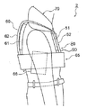
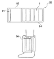
次に、体温調節パック1を首周りに装着するための専用の襟部パックホルダー70について、図25、図28〜30及び図34を参照して説明する。襟部パックホルダー70は矩形であり、図34に示すように、首周り専用のメッシュ袋71と、メッシュ袋71の両端に一体的に接続される襟ベルト73を有する。
<Collar pack holder>
Next, a dedicated collar pack holder 70 for mounting the body temperature regulation pack 1 around the neck will be described with reference to FIGS. 25, 28 to 30 and 34. As shown in FIG. 34, the collar pack holder 70 has a mesh bag 71 dedicated to the neck circumference and a collar belt 73 integrally connected to both ends of the mesh bag 71.

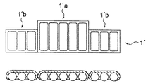
首周り専用のメッシュ袋71の内部には、図25に示すように、縦方向に長い体温調節パック1´aが首真後ろに該当する位置(メッシュ袋71の中央部分)に配置され、体温調節パック1´aよりも長さが短い一対の体温調節パック1´bが、体温調節パック1´aの両側の首側部に該当する位置に配置される。本実施例では、体温調節パック1´aには、細長袋状部22が横に5個分連結した高さ70mmの体温調節パックを用い、体温調節パック1´bには、細長袋状部22が横に3個分連結した高さ50mmの体温調節パックを用いている。複数の体温調節パック1´を挿入することによって、体温調節パック1´aと体温調節パック1´bとの境界でメッシュ袋71が曲がるので、体温調節パック1´を首周りの形に合わせて取り付けやすくなる。また、首両側の体温調節パック1´bの高さを低くすることにより、着用者の首の動きの邪魔になることがない。なお、体温調節パック1´の形状や数量はこれに限られることなく、例えば1個の矩形の体温調節パック1´をメッシュ袋71に封入してもよい。また、図34(c)に示すように、同じ長さ、同じ太さの第2実施形態の細長袋体322を複数本並べてメッシュ袋71に封入してもよい。また、この細長袋体322は、各々、大きさ、長さを変えて並べることもできる。   In the mesh bag 71 dedicated to the neck circumference, as shown in FIG. 25, a body temperature regulation pack 1'a that is long in the vertical direction is arranged at a position corresponding to the back of the neck (the center part of the mesh bag 71), and body temperature regulation is performed. A pair of body temperature regulation packs 1'b having a shorter length than the pack 1'a are arranged at positions corresponding to the neck side portions on both sides of the body temperature regulation pack 1'a. In this embodiment, the body temperature regulation pack 1′a is a body temperature regulation pack having a height of 70 mm in which five elongated bag-like portions 22 are connected horizontally, and the body temperature regulation pack 1′b has an elongated bag-like portion. A thermoregulation pack having a height of 50 mm, in which 22 are connected side by side by three, is used. By inserting a plurality of body temperature regulation packs 1 ', the mesh bag 71 bends at the boundary between the body temperature regulation pack 1'a and the body temperature regulation pack 1'b, so that the body temperature regulation pack 1' is adapted to the shape around the neck. Easy to install. Moreover, by lowering the height of the body temperature regulation pack 1'b on both sides of the neck, the movement of the neck of the wearer is not disturbed. The shape and quantity of the body temperature regulation pack 1 ′ are not limited to this, and for example, one rectangular body temperature regulation pack 1 ′ may be enclosed in the mesh bag 71. Further, as shown in FIG. 34 (c), a plurality of elongated bag bodies 322 of the second embodiment having the same length and the same thickness may be arranged and enclosed in the mesh bag 71. Further, the elongated bag bodies 322 can be arranged in different sizes and lengths.

メッシュ袋71の素材はメッシュ状布帛である。従って、体温調節パック1´を冷却目的に使う場合は、身体から放出された熱をより効率よく吸収することができる。また、体温調節パック1´を氷水につけて固相に戻す際には、メッシュ袋71がメッシュ素材であれば、いちいち体温調節パック1´を取り出さずに襟部パックホルダー70ごと氷水に浸して冷却することができる。一方、体温調節パック1´を保温目的で使用する場合、体温調節パック1´から放出された熱をより効率よく身体に伝えることができる。   The material of the mesh bag 71 is a mesh fabric. Therefore, when the body temperature regulation pack 1 ′ is used for cooling purposes, the heat released from the body can be absorbed more efficiently. Also, when the body temperature regulation pack 1 ′ is put on ice water and returned to the solid phase, if the mesh bag 71 is a mesh material, the collar pack holder 70 is immersed in ice water and cooled without taking out the body temperature regulation pack 1 ′. can do. On the other hand, when the body temperature regulation pack 1 ′ is used for heat insulation, the heat released from the body temperature regulation pack 1 ′ can be transmitted to the body more efficiently.

一対の襟ベルト73は、図34に示すようにメッシュ袋71の両端部に一体的に取り付けられる。また、メッシュ袋71と接続する端部とは反対側の端部72には、帯部65のループ状の面ファスナー布面と係合するためのフック状の面ファスナー91が設けられている。一対の襟ベルト73は着用者の胸部付近で斜交いに交差してそれぞれの端部72が帯部65の表面に達して、面ファスナー91を介して接続されるように適当な長さにされている。また、襟ベルト73は、その長手方向に弾性のある伸縮可能な布地より帯状に形成される。従って、襟ベルト73の端部72を帯部65の表面の何れの位置にでも着脱自在に接着できること及び襟ベルト73が伸縮可能であることにより、着用者の体格や必要とされる密着度に応じて、首周りの襟部パックホルダー70の密着性を調節することができる。なお、襟ベルト73を肩掛け部64に留めてもよい。また、首の動きの自由度が確保できるのであれば、首周りにぐるっと回して固定してもよい。   The pair of collar belts 73 are integrally attached to both ends of the mesh bag 71 as shown in FIG. A hook-shaped hook-and-loop fastener 91 for engaging with the loop-shaped hook-and-loop fastener cloth surface of the band portion 65 is provided at the end 72 opposite to the end connected to the mesh bag 71. The pair of collar belts 73 cross at an angle near the wearer's chest, and each end 72 reaches the surface of the band portion 65 and has an appropriate length so as to be connected via the hook-and-loop fastener 91. Has been. In addition, the collar belt 73 is formed in a belt shape from a stretchable fabric that is elastic in the longitudinal direction. Accordingly, the end portion 72 of the collar belt 73 can be detachably attached to any position on the surface of the band portion 65 and the collar belt 73 can be expanded and contracted, so that the wearer's physique and the required degree of adhesion can be achieved. Accordingly, the adhesion of the collar pack holder 70 around the neck can be adjusted. The collar belt 73 may be fastened to the shoulder portion 64. If the degree of freedom of movement of the neck can be ensured, it may be fixed by turning around the neck.

〈脚部パックホルダー〉
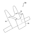
次に、体温調節パック1を脚部に装着するための専用の脚部パックホルダー90について、図35を参照して説明する。脚部パックホルダー90は矩形であり、図35に示すように、脚周り専用のメッシュ袋84と、メッシュ袋84の片側のみに一体的に接続される一対の脚ベルト83を有する。
<Leg pack holder>
Next, a dedicated leg pack holder 90 for mounting the body temperature regulation pack 1 on the legs will be described with reference to FIG. The leg pack holder 90 has a rectangular shape, and includes a mesh bag 84 dedicated to the legs and a pair of leg belts 83 that are integrally connected to only one side of the mesh bag 84, as shown in FIG.

脚周り専用のメッシュ袋84の内部には、図35に示すように、細長袋状部22が横に5個分連結した体温調節パック1が封入されている。但し、体温調節パック1の形状や数量はこれに限られることはない。また、第2実施形態の細長袋体322を各々、大きさ、長さを変えて並べてもよい。   As shown in FIG. 35, a body temperature regulation pack 1 in which five elongate bag-like portions 22 are connected horizontally is enclosed in the mesh bag 84 dedicated to the legs. However, the shape and quantity of the body temperature regulation pack 1 are not limited to this. Moreover, you may arrange the elongate bag body 322 of 2nd Embodiment, changing a magnitude | size and length, respectively.

メッシュ袋84の素材はメッシュ状布帛である。従って、体温調節パック1を身体の保温目的で使用する場合、体温調節パック1から放出された熱をより効率よく身体に伝えることができる。一方、体温調節パック1を身体の冷却目的に使う場合は、身体から放出された熱をより効率よく吸収することができる。また、体温調節パック1を氷水につけて固相に戻す際には、メッシュ袋84がメッシュ素材であれば、いちいち体温調節パック1を取り出さずに脚部パックホルダー90ごと氷水に浸して冷却することができる。   The material of the mesh bag 84 is a mesh fabric. Therefore, when the body temperature regulation pack 1 is used for the purpose of keeping the body warm, the heat released from the body temperature regulation pack 1 can be transmitted to the body more efficiently. On the other hand, when the body temperature regulation pack 1 is used for cooling the body, the heat released from the body can be absorbed more efficiently. In addition, when the body temperature regulation pack 1 is put on ice water and returned to the solid phase, if the mesh bag 84 is a mesh material, the leg pack holder 90 and the whole leg pack holder 90 are immersed and cooled without taking out the body temperature regulation pack 1 each time. Can do.

脚ベルト83は、図35に示すようにメッシュ袋84の片側に一体的に取り付けられる。また、脚ベルト83の、メッシュ袋84と接続する端部とは反対側の端部82には、フック状の面ファスナー81が設けられている。また脚部パックホルダー90の身体と接しない側の面は、ループ状の面ファスナーとなっている。着用者は、図36のように脚部パックホルダー80を脚部に巻きつけて、脚ベルト83の面ファスナー81を脚部パックホルダー90の面ファスナーに係合して、自由な位置に着脱自在に留めることができる。また、脚ベルト83は、その長手方向に弾性のある伸縮可能な布地より帯状に形成される。従って、帯ベルト83の端部82を脚部パックホルダー90の表面の何れの位置にでも着脱自在に接着できること及び帯ベルト83が伸縮可能であることにより、着用者の体格や必要とされる密着度に応じて、脚周りの脚部パックホルダー90の密着性を調節することができる。
但し、脚ベルト83の形状は本実施例に限定されず、メッシュ袋84の一端に1本の脚ベルト83が接続され、メッシュ袋84自体が面ファスナーとなっており、脚ベルト83の面ファスナー81とメッシュ袋84自体が係合するようになっていてもよい。また、脚ベルト83の面ファスナー81がループ状で、脚部パックホルダー90の面ファスナーがフック状であってもよい。
The leg belt 83 is integrally attached to one side of the mesh bag 84 as shown in FIG. A hook-shaped hook-and-loop fastener 81 is provided on the end 82 of the leg belt 83 opposite to the end connected to the mesh bag 84. Further, the surface of the leg pack holder 90 that is not in contact with the body is a loop-shaped surface fastener. As shown in FIG. 36, the wearer wraps the leg pack holder 80 around the leg, engages the hook-and-loop fastener 81 of the leg belt 83 with the hook-and-loop fastener of the leg pack holder 90, and can be freely attached and detached. Can be stopped. Further, the leg belt 83 is formed in a belt shape from a stretchable fabric that is elastic in the longitudinal direction. Accordingly, the end portion 82 of the belt belt 83 can be detachably attached to any position on the surface of the leg pack holder 90, and the belt belt 83 can be expanded and contracted, so that the wearer's physique and the necessary adhesion can be obtained. Depending on the degree, the adhesion of the leg pack holder 90 around the legs can be adjusted.
However, the shape of the leg belt 83 is not limited to this embodiment, and one leg belt 83 is connected to one end of the mesh bag 84, and the mesh bag 84 itself is a hook-and-loop fastener. 81 and the mesh bag 84 itself may be engaged. Further, the hook-and-loop fastener 81 of the leg belt 83 may be loop-shaped, and the hook-and-loop fastener of the leg pack holder 90 may be hook-shaped.

なお、寒冷期における屋外作業、或いは暖房器具のない作業所においては、従来から、作業者にとって上半身の保温は比較的容易であるが、脚部の効率的な保温がままならず、足元からの冷えを辛く感じるという問題があったため、脚部パックホルダー90は主に保温目的に使われるものである。体温調節パック1は、液相の状態でも変形しないため、ムラなく脚部を保温することができ、さらに、固液相変化材料が固相となっても、自在に曲げたり延ばしたりすることが可能であるため、体の形に沿って曲がっていたものを容易に取り外すことができる。
但し、脚部パックホルダー90は、上記のように身体の冷却目的として使用してもよい。
In addition, it has been relatively easy for an operator to keep the upper body warm in outdoor work in the cold season or in a work place without a heater, but it does not maintain the effective heat of the legs and keeps it cool from the feet. Due to the problem of feeling painful, the leg pack holder 90 is mainly used for heat insulation purposes. Since the body temperature regulation pack 1 is not deformed even in the liquid phase, the leg portion can be kept warm evenly, and even if the solid-liquid phase change material becomes a solid phase, it can be bent or extended freely. Since it is possible, what was bent along the shape of a body can be removed easily.
However, the leg pack holder 90 may be used for cooling the body as described above.

以下、上述したパックホルダー2全体の利点を説明する。
まず、冷却目的で使用する体温調節パック1について説明するが、本発明の体温調節パック1には、固液相変化材料10とともに断熱材30も封入されているため、パックホルダー2に断熱機能を持たせる必要がない。ここで、体温調節パック1内の固液相変化材料10を液相から固相に戻す際の方法は、時間的に短いほうから記すと
(1)大目の氷水に浸ける。
(2)川などの流水に浸ける。
(3)冷蔵庫に入れる。
(4)22℃以下の室温で放置する。
となる。従来の断熱機能をもったパックホルダーの場合は、体温調節パックをパックホルダーに入れたまま冷却しようとしても、嵩張るため、(1)及び(2)の方法では水に浸け辛く、パックホルダー自体が水分を含み重くなる。また、(3)の方法では、パックホルダーが嵩張る分、冷蔵庫のスペースを無駄にとってしまう。さらに(4)の方法では、冷却に時間がかかるため、(1)等の方法を採用するほうが望ましい。
Hereinafter, advantages of the entire pack holder 2 described above will be described.
First, the body temperature regulation pack 1 used for cooling purposes will be described. Since the body temperature regulation pack 1 according to the present invention includes the solid-liquid phase change material 10 and the heat insulation material 30, the heat insulation function is provided to the pack holder 2. There is no need to have it. Here, the method for returning the solid-liquid phase change material 10 in the body temperature regulation pack 1 from the liquid phase to the solid phase is described as follows: (1) It is immersed in a large ice water.
(2) Immerse in running water such as rivers.
(3) Put in the refrigerator.
(4) Leave at room temperature below 22 ° C.
It becomes. In the case of a conventional pack holder having a heat insulating function, even if it is attempted to cool the body temperature control pack while being put in the pack holder, it is bulky, so the methods (1) and (2) are difficult to immerse in water. Contains moisture and becomes heavy. In the method (3), the space of the refrigerator is wasted as the pack holder is bulky. Furthermore, in the method (4), since it takes time to cool, it is preferable to adopt the method (1) or the like.

また、防護服等の下にパックホルダーを装着する場合は、呼吸保護具その他の身体保護具を追加するため、衣服全体が重くなる傾向にある。従って、パックホルダー自体には余分な重みが加わらず、できる限り嵩張らず軽量なものとすることが望ましい。また、呼吸器具等の装備には必ずハーネスが必要となるが、ハーネスにはもともとパットが入っているため、パックホルダー自体に断熱材を取り付けるのは無用な重複である。   In addition, when the pack holder is mounted under protective clothing or the like, the entire clothing tends to be heavy because a respiratory protective device or other body protective device is added. Therefore, it is desirable that the pack holder itself is not excessively weighted and is as light as possible without being bulky. In addition, a harness is always required for equipment such as breathing apparatus, but it is useless to attach a heat insulating material to the pack holder itself because a harness is originally contained in the harness.

これらの問題点に鑑みて、本発明のパックホルダー2自体には断熱機能をもたせず、体温調節パック1に断熱材を封入することで、パックホルダー2を軽量化し、嵩張らないものとすることができる。また、パックホルダー2が水に濡らしても乾きやすいメッシュ状素材でできていることにより、パックホルダー2ごと氷水に浸けて冷却することができる。さらに、メッシュ状布帛を透して、パックホルダー2全体に水や空気が対流しやすいスケルトン状態となるので、固液相変化材料10の機能回復効率をより向上させることが可能となる。またさらに、パックホルダー2自体の軽量化、スリム化を達成できるだけでなく、体温調節パック1の配置場所、配置数、パックサイズの選定が自在であるため、呼吸保護具等の必要設備に干渉して安全性を阻害する危険が少ない。また、通常一定時間の作業をしている着用者が特別に長い作業を行いたい場合は、メッシュ袋を、サイズが大きい体温調節パック1が封入されたものに交換することで容易にその目的を達成することができる。   In view of these problems, the pack holder 2 itself of the present invention does not have a heat insulating function, and by encapsulating a heat insulating material in the body temperature regulation pack 1, the pack holder 2 is reduced in weight and is not bulky. it can. Further, since the pack holder 2 is made of a mesh-like material that is easy to dry even when wet, it can be cooled by immersing the pack holder 2 in ice water. Furthermore, since the mesh-like fabric is passed through and the skeleton state in which water and air are easily convected through the entire pack holder 2 is obtained, the function recovery efficiency of the solid-liquid phase change material 10 can be further improved. Furthermore, not only can the pack holder 2 itself be reduced in weight and size, but also the location, number, and pack size of the body temperature control pack 1 can be freely selected, which interferes with necessary equipment such as respiratory protection equipment. And there is little risk of hindering safety. In addition, when a wearer who normally works for a certain period of time wants to perform a particularly long work, the mesh bag can be easily replaced by a large-size body temperature control pack 1 enclosed therein. Can be achieved.

固液相変化材料からなる冷却材を装着し、下腹部を除く上半身に密着させて、その上に熱の逃げ場のない衣服(主に防護服等に相当するもの)を着用する耐久テストを行った結果、体感として、「一箇所でよいから冷たい箇所がほしい。一箇所よりは胸や背中に二箇所あれば、なお望ましい。さらに、二箇所よりは首や脇下にも冷たい箇所がほしい。また、各部位をなるべく広く冷やしたいが、すぐ融けるよりは熱吸収面積が狭くても長時間、熱吸収効果が持続するのが望ましい」という結論に至った。従って、本発明のパックホルダー2は、これらの目的を達成するために、任意の部位に任意のサイズの体温調節パック1を配備することができるような構成となっている。   Durability test is performed in which a coolant made of a solid-liquid phase change material is attached and in close contact with the upper body excluding the lower abdomen, and on which clothing without heat escape (mainly equivalent to protective clothing) is worn. As a result, the experience is: “I want a cold spot because it is good in one place. It is more desirable to have two places on the chest and back than one place. In addition, I want cold places on the neck and armpits more than two places. In addition, although it is desired to cool each part as widely as possible, it is desirable that the heat absorption effect should last for a long time even if the heat absorption area is small rather than melting immediately. Therefore, the pack holder 2 of the present invention is configured such that the body temperature regulation pack 1 of any size can be deployed at any location in order to achieve these objects.

以上、本発明の好適な実施形態について説明したが、本発明は上述の実施の形態に限られるものではなく、特許請求の範囲において様々な変更が可能なものである。   The preferred embodiments of the present invention have been described above. However, the present invention is not limited to the above-described embodiments, and various modifications can be made within the scope of the claims.

1 体温調節パック
2 パックホルダー
10 固液相変化材料
20 インナーパック
22 細長袋状部
30 断熱材
40 アウターパック
50 前面部
60 後面部
65 帯部
70 襟部パックホルダー
80 胴体パックホルダー
90 脚部パックホルダー
100体温調節パック
322細長袋体
DESCRIPTION OF SYMBOLS 1 Body temperature control pack 2 Pack holder 10 Solid-liquid phase change material 20 Inner pack 22 Elongate bag-like part 30 Heat insulating material 40 Outer pack 50 Front part 60 Rear part 65 Band part 70 Collar part pack holder 80 Body pack holder 90 Leg part pack holder 100 body temperature regulation pack 322 elongated bag

Claims (11)

内部に固液相変化材料が充填される体温調節パックにおいて、
該体温調節パックは、平行に配列される複数の袋体を備え、
該複数の袋体の内部には前記固液相変化材料が隙間なく充填されていることを特徴とする体温調節パック。
In the thermoregulation pack in which the solid-liquid phase change material is filled,
The body temperature regulation pack includes a plurality of bags arranged in parallel,
The body temperature regulation pack, wherein the plurality of bags are filled with the solid-liquid phase change material without any gaps.
前記袋体の各々は、細長い円筒形状であることを特徴とする請求項1記載の体温調節パック。   The body temperature regulation pack according to claim 1, wherein each of the bags has an elongated cylindrical shape. 前記複数の袋体は、各々独立した細長袋体からなる請求項1又は2記載の体温調節パック。   The body temperature regulation pack according to claim 1 or 2, wherein each of the plurality of bags is formed of an independent elongated bag. 前記複数の袋体は、一対のインナーシートの周囲の縁部を貼り合わせると共に、平行に複数ケ所溶着することにより形成された細長袋状部からなる請求項1又は2記載の体温調節パック。   3. The body temperature regulation pack according to claim 1, wherein the plurality of bag bodies are formed of elongated bag-like portions formed by bonding peripheral edges of a pair of inner sheets and welding in parallel at a plurality of locations. 前記体温調節パックの片面は断熱材で覆われることを特徴とする請求項1〜4のいずれかに記載の体温調節パック。   The body temperature regulation pack according to any one of claims 1 to 4, wherein one surface of the body temperature regulation pack is covered with a heat insulating material. 前記固液相変化材料は、硫酸ナトリウム、酢酸ナトリウムあるいはノルマルパラフィンのいずれかひとつを含有する請求項1〜5のいずれか記載の体温調節パック。   The body temperature regulation pack according to any one of claims 1 to 5, wherein the solid-liquid phase change material contains any one of sodium sulfate, sodium acetate, and normal paraffin. 請求項1〜6のいずれかに記載の体温調節パックを身体側に取り付ける胴体パックホルダーであって、
該体温調節パックを任意の場所に着脱自在に取り付けることができることを特徴とする胴体パックホルダー。
A body pack holder for attaching the body temperature regulation pack according to any one of claims 1 to 6 to the body side,
A body pack holder characterized in that the body temperature regulation pack can be detachably attached to an arbitrary place.
前記胴体パックホルダーは、着用者の胸部を覆う前面部と、着用者の背中を覆う後面部とを有し、
該前面部と該後面部とは、それぞれ着脱可能に接続されることを特徴とする請求項7記載の胴体パックホルダー。
The torso pack holder has a front part covering the chest of the wearer and a rear part covering the back of the wearer,
The fuselage pack holder according to claim 7, wherein the front surface portion and the rear surface portion are detachably connected to each other.
前記前面部と前記後面部とは、それぞれ伸縮自在な紐状体によって接続されることを特徴とする請求項8記載の胴体パックホルダー。   The fuselage pack holder according to claim 8, wherein the front surface portion and the rear surface portion are connected to each other by a stretchable string-like body. 請求項1〜6のいずれかに記載の体温調節パックを首周りに着脱自在に取り付けることを特徴とする襟部パックホルダー。   A collar pack holder, wherein the body temperature regulation pack according to any one of claims 1 to 6 is detachably attached to the neck. 請求項1〜6のいずれかに記載の体温調節パックを脚部に着脱自在に取り付けることを特徴とする脚部パックホルダー。   A leg pack holder, wherein the body temperature regulation pack according to any one of claims 1 to 6 is detachably attached to the leg section.
JP2011132056A 2010-12-24 2011-06-14 Body temperature regulation pack and pack holder for attaching the body temperature regulation pack Pending JP2012143533A (en)

Priority Applications (6)

Application Number Priority Date Filing Date Title
JP2011132056A JP2012143533A (en) 2010-12-24 2011-06-14 Body temperature regulation pack and pack holder for attaching the body temperature regulation pack
EP11850663.3A EP2657629A1 (en) 2010-12-24 2011-12-21 Body temperature regulation pack and pack holder for attaching body temperature regulation pack
PCT/JP2011/079611 WO2012086676A1 (en) 2010-12-24 2011-12-21 Body temperature regulation pack and pack holder for attaching body temperature regulation pack
US13/995,558 US20130289680A1 (en) 2010-12-24 2011-12-21 Body temperature regulation pack and pack holder for attaching body temperature regulation pack
CA2822046A CA2822046A1 (en) 2010-12-24 2011-12-21 Body temperature regulation pack and pack holder for attaching body temperature regulation pack
KR1020137019569A KR20140020853A (en) 2010-12-24 2011-12-21 Body temperature regulation pack and pack holder for attaching body temperature regulation pack

Applications Claiming Priority (3)

Application Number Priority Date Filing Date Title
JP2010288725 2010-12-24
JP2011132056A JP2012143533A (en) 2010-12-24 2011-06-14 Body temperature regulation pack and pack holder for attaching the body temperature regulation pack

Publications (1)

Publication Number Publication Date
JP2012143533A true JP2012143533A (en) 2012-08-02

Family

ID=46313944

Family Applications (1)

Application Number Title Priority Date Filing Date
JP2011132056A Pending JP2012143533A (en) 2010-12-24 2011-06-14 Body temperature regulation pack and pack holder for attaching the body temperature regulation pack

Country Status (6)

Country Link
US (1) US20130289680A1 (en)
EP (1) EP2657629A1 (en)
JP (1) JP2012143533A (en)
KR (1) KR20140020853A (en)
CA (1) CA2822046A1 (en)
WO (1) WO2012086676A1 (en)

Cited By (5)

* Cited by examiner, † Cited by third party
Publication number Priority date Publication date Assignee Title
JP3179185U (en) * 2012-08-07 2012-10-18 株式会社ベガコーポレーション Cooling mat
JP2013145780A (en) * 2012-01-13 2013-07-25 Panasonic Corp Power generation device
CN103637409A (en) * 2013-11-20 2014-03-19 苏州工业园区友顺制衣厂 Coat with automatic heat producing function
WO2017022241A1 (en) * 2015-08-04 2017-02-09 パナソニックIpマネジメント株式会社 Insulating sheet, and seatback-equipped seat and cold weather garment employing same
JP2018193649A (en) * 2017-05-19 2018-12-06 株式会社鎌倉製作所 Garment

Families Citing this family (27)

* Cited by examiner, † Cited by third party
Publication number Priority date Publication date Assignee Title
US11684510B2 (en) 2006-04-20 2023-06-27 University of Pittsburgh—of the Commonwealth System of Higher Education Noninvasive, regional brain thermal stimuli for the treatment of neurological disorders
US8425583B2 (en) 2006-04-20 2013-04-23 University of Pittsburgh—of the Commonwealth System of Higher Education Methods, devices and systems for treating insomnia by inducing frontal cerebral hypothermia
US9211212B2 (en) 2006-04-20 2015-12-15 Cerêve, Inc. Apparatus and method for modulating sleep
US20150238725A1 (en) * 2008-10-20 2015-08-27 Cereve, Inc. Non-invasive brain temperature regulating devices for enhancing sleep
WO2014107509A1 (en) 2013-01-02 2014-07-10 Cerêve, Inc. Systems for enhancing sleep
SG11201505024RA (en) * 2013-01-04 2015-07-30 Evonik Oil Additives Gmbh Preparation of low-viscosity polymers
US20140379058A1 (en) * 2013-06-24 2014-12-25 Ampac Enterprises Inc. Apparatus and Method for Cooling Head Injury
FR3012588A1 (en) * 2013-10-25 2015-05-01 Daniel Cholet COMPRESSOR PLATE FOR THERMAL BATTERY FOR USE OF COLD ACCUMULATOR BLOCK
KR102236776B1 (en) * 2014-09-05 2021-04-06 삼성전자주식회사 An evaporator, an refrigerator using the evaporator and a method for controlling the refrigerator
US20170042259A1 (en) * 2015-08-10 2017-02-16 Cheryl Ann Ball Wearable Cooling Apparatus
US11964795B2 (en) * 2015-10-06 2024-04-23 Cold Chain Technologies, Llc Device comprising one or more temperature-control members and kit for use in making the device
US10583978B2 (en) 2015-10-06 2020-03-10 Cold Chain Technologies, Llc Pallet cover compromising one or more temperature-control members and kit for use in making the pallet cover
US11591133B2 (en) 2015-10-06 2023-02-28 Cold Chain Technologies, Llc Pallet cover comprising one or more temperature-control members and kit for use in making the pallet cover
US10604326B2 (en) 2015-10-06 2020-03-31 Cold Chain Technologies, Llc. Pallet cover comprising one or more temperature-control members and kit for use in making the pallet cover
USD773681S1 (en) * 2015-11-04 2016-12-06 The Regents Of The University Of California Infant warming pad
US10687632B1 (en) 2016-04-03 2020-06-23 Soothsoft Innovations Worldwide, Inc. PCM containing liquid saturated foam device
US20170296381A1 (en) * 2016-04-14 2017-10-19 Paul Fox Sportswear cooling system
DE102016108829A1 (en) * 2016-05-12 2017-11-16 Laurens G. J. Wolters Thermal storage means
DK3249335T3 (en) * 2016-05-27 2021-05-25 Axiotherm GmbH LATENT HEAT STORAGE ELEMENT, ENCLOSURE TO A LATENT HEAT STORAGE MATERIAL AND LATENT HEAT STORAGE
EP3634881B1 (en) * 2017-05-15 2024-04-03 Cold Chain Technologies, LLC Pallet cover comprising temperature-control members
US10660791B2 (en) * 2017-09-11 2020-05-26 Hillel Zakai Personal cooling system and method of operation
KR101907613B1 (en) 2017-09-20 2018-10-12 임재록 hip guard
US20200300551A1 (en) * 2019-03-21 2020-09-24 Hamilton Sundstrand Corporation Heat exchanger temperature change rate control
US11058573B2 (en) * 2019-05-31 2021-07-13 Jim E. Fulbrook Heating / cooling body treatment therapy pad system
US20210069045A1 (en) * 2019-09-11 2021-03-11 The Regents Of The University Of California Differential-melting point PCM as safety indicator for warming devices
KR200494033Y1 (en) * 2020-08-26 2021-07-20 (주)에프엠에스코리아 Cool and hot pack and cool and hot vest using the same
CN113456339B (en) * 2021-05-24 2023-12-05 丰都县疾病预防控制中心(丰都县健康教育中心) Medical human body cooling equipment

Citations (9)

* Cited by examiner, † Cited by third party
Publication number Priority date Publication date Assignee Title
JPS5787276U (en) * 1980-11-19 1982-05-29
JPS59180182U (en) * 1983-05-19 1984-12-01 住友ゴム工業株式会社 Cooler with insulation cover
JPH0522514U (en) * 1991-07-24 1993-03-23 日本自動車整備商工組合連合会 Salopette and pants
US6185742B1 (en) * 1998-10-23 2001-02-13 Brian Doherty Cool garment
JP2002309414A (en) * 2001-04-10 2002-10-23 Aichi Corp Wear having cooling function
JP2007169858A (en) * 2005-12-26 2007-07-05 Aitosu Kk Working wear
JP2007528945A (en) * 2003-07-18 2007-10-18 ロイヤル・メルボルン・インスティテュート・オブ・テクノロジー Cooling clothing
JP2009119197A (en) * 2007-10-21 2009-06-04 Susumu Kiyokawa Perspiration device
JP2009127147A (en) * 2007-11-26 2009-06-11 Agri Soken:Kk Cooling garment

Family Cites Families (41)

* Cited by examiner, † Cited by third party
Publication number Priority date Publication date Assignee Title
US3950789A (en) * 1975-07-22 1976-04-20 Kansas State University Research Foundation Dry ice cooling jacket
US4033354A (en) * 1975-12-05 1977-07-05 Rosa Maria I De Cooling garment
US4384369A (en) * 1981-05-11 1983-05-24 Lyndonn Prince Exercise suit
US4576169A (en) * 1984-07-26 1986-03-18 Williams Annie J Comfort collar
US4856294B1 (en) * 1988-02-04 1997-05-13 Mainstream Engineering Corp Micro-climate control vest
US5072455A (en) * 1989-02-27 1991-12-17 St Ours Thomas A Heat-intercepting garment or blanket
US5074285A (en) * 1989-11-20 1991-12-24 Wright Linear Pump, Inc. Thermal applicator method
US5146625A (en) * 1991-03-27 1992-09-15 Steele And Associates, Inc. Cooling vest
US5088549A (en) * 1991-06-13 1992-02-18 Warren Locke Franz Tying neckband heat transfer device
US5265669A (en) * 1991-06-13 1993-11-30 Schneider Mark R Tying neckband heat transfer device
US5305471A (en) * 1992-02-20 1994-04-26 Steele And Associates, Inc. Insulated cooling vest
US6004662A (en) * 1992-07-14 1999-12-21 Buckley; Theresa M. Flexible composite material with phase change thermal storage
US5295949A (en) * 1992-09-18 1994-03-22 Charles Hathaway Modular neck apparatus
US5484448A (en) * 1993-05-07 1996-01-16 Steele And Associates, Inc. Garment and method for cooling body temperature
IT230352Y1 (en) * 1993-07-15 1999-06-02 Roberto Ragonesi LOCALIZED COOLING DEVICE OF PARTS OF THE HUMAN BODY
US5415222A (en) * 1993-11-19 1995-05-16 Triangle Research & Development Corporation Micro-climate cooling garment
JPH08199408A (en) * 1995-01-18 1996-08-06 Ashimori Ind Co Ltd Cooling wear
US5692238A (en) * 1996-06-19 1997-12-02 Watson, Jr.; Jerry O. Body comforter
US6125645A (en) * 1997-06-12 2000-10-03 Horn; Stephen T. Moisture removal phase shift personal cooling Garment
US6185744B1 (en) * 1998-01-26 2001-02-13 Mike Poholski Thermal vest
US6189149B1 (en) * 1999-12-16 2001-02-20 Jeffrey B. Allen Temperature change vest
US6755852B2 (en) * 2001-12-08 2004-06-29 Charles A. Lachenbruch Cooling body wrap with phase change material
JP2003328213A (en) 2002-05-10 2003-11-19 Aichi Corp Clothing having cooling function, cooling material and method for using the same
US6918236B2 (en) * 2002-08-14 2005-07-19 Ortho-Care, Inc. Breathable equine leg wrap
US7096687B2 (en) * 2003-06-06 2006-08-29 Albert Long Trinh Non-constrictive ice bag device
US7065983B2 (en) * 2003-06-06 2006-06-27 Albert Long Trinh Adhesive ice bag device
US6931875B1 (en) * 2004-04-19 2005-08-23 Jeffrey Allen Cooling vest system
US8499367B2 (en) * 2004-07-02 2013-08-06 Createc Consulting, Llc Cooling garment having phase change material in its extremity portions
US20060064147A1 (en) * 2004-07-02 2006-03-23 Almqvist Hans O Cooling garment having phase change material in its extremity portions
US8449588B2 (en) * 2006-09-25 2013-05-28 Stephen T. Horn and Phyllis Horn Joint Tenure IP Common Duration and comfort in cooling vest
US7762096B2 (en) * 2006-12-15 2010-07-27 Fuchs Mark D Temperature control vest having visible ice sheets composed of refrigerant cubes
US20080208299A1 (en) * 2007-02-28 2008-08-28 Sylvain Martineau Thermo-therapeutic cushion
US8585746B2 (en) * 2007-08-29 2013-11-19 Nike, Inc. Article of apparel for temperature moderation
US20090216305A1 (en) * 2008-02-22 2009-08-27 Larry Herman Bonner Thermal, outer layer leg wrap device
BRPI0913060A2 (en) * 2008-05-12 2015-10-13 Embrace a system and method for regulating temperature
JP2010255152A (en) 2009-04-28 2010-11-11 Alpha Giken:Kk Cold insulator and garment
US9265654B2 (en) * 2009-05-11 2016-02-23 Steven H. Gallaher Cooling article of clothing and method of use for same
US8950207B2 (en) * 2010-03-30 2015-02-10 Hyper Wear, Inc. Device for stimulating adaptive thermogenesis in brown adipose tissue
US20110239346A1 (en) * 2010-04-05 2011-10-06 Brian Doherty Microclimate System for Protective Body Armor
US20120167288A1 (en) * 2011-01-04 2012-07-05 Yishuo Chen Thermal Vest
US20120285191A1 (en) * 2011-05-09 2012-11-15 Gallaher Steven H Cooling Clothing System and Method for Use of Same

Patent Citations (9)

* Cited by examiner, † Cited by third party
Publication number Priority date Publication date Assignee Title
JPS5787276U (en) * 1980-11-19 1982-05-29
JPS59180182U (en) * 1983-05-19 1984-12-01 住友ゴム工業株式会社 Cooler with insulation cover
JPH0522514U (en) * 1991-07-24 1993-03-23 日本自動車整備商工組合連合会 Salopette and pants
US6185742B1 (en) * 1998-10-23 2001-02-13 Brian Doherty Cool garment
JP2002309414A (en) * 2001-04-10 2002-10-23 Aichi Corp Wear having cooling function
JP2007528945A (en) * 2003-07-18 2007-10-18 ロイヤル・メルボルン・インスティテュート・オブ・テクノロジー Cooling clothing
JP2007169858A (en) * 2005-12-26 2007-07-05 Aitosu Kk Working wear
JP2009119197A (en) * 2007-10-21 2009-06-04 Susumu Kiyokawa Perspiration device
JP2009127147A (en) * 2007-11-26 2009-06-11 Agri Soken:Kk Cooling garment

Cited By (6)

* Cited by examiner, † Cited by third party
Publication number Priority date Publication date Assignee Title
JP2013145780A (en) * 2012-01-13 2013-07-25 Panasonic Corp Power generation device
JP3179185U (en) * 2012-08-07 2012-10-18 株式会社ベガコーポレーション Cooling mat
CN103637409A (en) * 2013-11-20 2014-03-19 苏州工业园区友顺制衣厂 Coat with automatic heat producing function
WO2017022241A1 (en) * 2015-08-04 2017-02-09 パナソニックIpマネジメント株式会社 Insulating sheet, and seatback-equipped seat and cold weather garment employing same
JPWO2017022241A1 (en) * 2015-08-04 2018-05-24 パナソニックIpマネジメント株式会社 Insulation sheet, seat with backrest using the same, and winter clothes
JP2018193649A (en) * 2017-05-19 2018-12-06 株式会社鎌倉製作所 Garment

Also Published As

Publication number Publication date
KR20140020853A (en) 2014-02-19
WO2012086676A1 (en) 2012-06-28
CA2822046A1 (en) 2012-06-28
US20130289680A1 (en) 2013-10-31
EP2657629A1 (en) 2013-10-30

Similar Documents

Publication Publication Date Title
WO2012086676A1 (en) Body temperature regulation pack and pack holder for attaching body temperature regulation pack
US7243509B2 (en) Thermal therapeutic method
CA2593685C (en) Thermotherapeutic pad
US20060276089A1 (en) Cooling garment
US7780713B2 (en) Heat absorbing pack
WO2001039705A1 (en) Cooling pad
KR20140141161A (en) ice neck band using phase change materials
US20130220297A1 (en) Heat Generating Single-Use Garment
US20140107739A1 (en) Reusable hot / cold wrap
US10179075B1 (en) Shoulder thermal therapy wrap
JPWO2017187774A1 (en) Therapeutic tool used for cold storage and cooling therapy
KR20100093230A (en) Neck band
US20180071139A1 (en) Body temperature regulating device
CN209580697U (en) A kind of moisture absorbing and sweat releasing and warming clothes
JP4361413B2 (en) Pet belly band
JP3182615U (en) Cooling tool
JP2011038214A (en) Children&#39;s muffler type cooling item
CN213819974U (en) Cooling jacket
JPH11217707A (en) Vest
JP3147806U (en) Child wrapping cooler
US20220354088A1 (en) Cooling structure or assembly using phase change material
JP2010255152A (en) Cold insulator and garment
JP3156195U (en) Icing eye mask and cooling zone
CN215286110U (en) Self-heating thermal suit under cold condition
JP3175412U (en) Cooler

Legal Events

Date Code Title Description
A621 Written request for application examination

Free format text: JAPANESE INTERMEDIATE CODE: A621

Effective date: 20131209

A131 Notification of reasons for refusal

Free format text: JAPANESE INTERMEDIATE CODE: A131

Effective date: 20150519

A02 Decision of refusal

Free format text: JAPANESE INTERMEDIATE CODE: A02

Effective date: 20151006