JP2012143398A - Endoscope system and image generating method - Google Patents
Endoscope system and image generating method Download PDFInfo
- Publication number
- JP2012143398A JP2012143398A JP2011004194A JP2011004194A JP2012143398A JP 2012143398 A JP2012143398 A JP 2012143398A JP 2011004194 A JP2011004194 A JP 2011004194A JP 2011004194 A JP2011004194 A JP 2011004194A JP 2012143398 A JP2012143398 A JP 2012143398A
- Authority
- JP
- Japan
- Prior art keywords
- image signal
- image
- light
- signal
- wavelength
- Prior art date
- Legal status (The legal status is an assumption and is not a legal conclusion. Google has not performed a legal analysis and makes no representation as to the accuracy of the status listed.)
- Pending
Links
Images


Abstract
Description
本発明は、血中ヘモグロビンの酸素飽和度に関する情報を画像化する内視鏡システム及び画像生成方法に関する。 The present invention relates to an endoscope system and an image generation method for imaging information related to oxygen saturation of blood hemoglobin.
近年の医療においては、内視鏡装置を用いた診断等が広く行われている。内視鏡装置による被検体内の観察としては、照明光として広帯域光の白色光を用いる通常光観察の他、波長を狭帯域化した狭帯域光を用いて、被検体内の血管を強調表示等させる特殊光観察も行われるようになってきている。 In recent medical treatments, diagnosis using an endoscope apparatus is widely performed. For observation of the inside of the subject using an endoscope device, in addition to normal light observation using broadband white light as illumination light, blood vessels in the subject are highlighted using narrowband light with a narrowed wavelength. Special light observation is also being carried out.
また、特殊光観察の他に、血中ヘモグロビンの酸素飽和度などの被検体の機能情報を画像化することも行われている。例えば、特許文献1では、血中ヘモグロビンの酸素飽和度に応じて光吸収が変化する波長の光を被検体に照射し、それぞれの光の反射光等を撮像したときの画像信号に基づいて疑似カラーで酸素飽和度を表示している。この特許文献1では、酸素飽和度により光吸収が変化する波長の光の他に、光吸収が変化しない波長の光を含む複数波長の光を、それぞれ時系列で順に被検体内に照射している(面順次方式)。
In addition to special light observation, functional information of the subject such as oxygen saturation of blood hemoglobin is also imaged. For example, in
このように波長が異なる光が被検体内に順次照射されることで、例えば、酸素飽和度により光吸収が変化する波長の光を照射したときの配光分布と、光吸収が変化しない波長の光を照射したときの配光分布に違いがでることがある。この配光分布の違いは正確な酸素飽和度の表示を妨げるものとなり、特に画像辺縁部分での酸素飽和度の表示が不適切になる可能性が高い。 By sequentially irradiating the subject with light having different wavelengths in this manner, for example, the distribution of light distribution when light having a wavelength that changes light absorption depending on the degree of oxygen saturation and the wavelength at which light absorption does not change. There may be a difference in the light distribution when irradiated with light. This difference in light distribution hinders accurate display of oxygen saturation, and in particular, there is a high possibility that the display of oxygen saturation at the edge of the image will be inappropriate.
配光分布の違いを補正する方法としては、特許文献2に、広帯域光の白色光を照射したときの配光分布とその白色光と波長域が異なる励起光を照射したときの配光分布の違いを補正する方法が示されている。この特許文献2の方法は、上述したような、酸素飽和度により光吸収が変化する波長の光の配光分布と変化しない波長の光の配光分布の違いを補正する場合にも適用できると考えられる。
As a method for correcting the difference in the light distribution,
特許文献2では、白色光と励起光における配光分布の違いを補正するために用いられる補正データを求める際、標準被写体を内面に備えたキャップを内視鏡スコープ先端部に装着した状態で、白色光を照射及び撮像したときの標準被写体の白色光画像と、励起光を照射及び撮像したときの励起光画像とを取得し、取得した画像から補正データを求めている。そして、実際の内視鏡診断時(自家蛍光観察時)には、その予め算出した補正データを用いて画像の補正を行っている。
In
したがって、補正データは、キャップを装着したときの配光光学系とキャップ内面の標準被写体の位置関係の場合の配光分布の違いに基づいて得られるものであるため、実際に被検体内の被写体組織を観察する時のように、スコープと被写体組織との位置関係が距離・角度とともに様々に変化する場合には、予め求めた補正データでは配光分布の違いを正しく補正できない可能性がある。 Therefore, the correction data is obtained based on the difference in the light distribution in the case of the positional relationship between the light distribution optical system when the cap is attached and the standard object on the inner surface of the cap. When the positional relationship between the scope and the subject tissue varies with distance and angle as in the case of observing the tissue, there is a possibility that the difference in the light distribution cannot be corrected correctly with the correction data obtained in advance.
本発明は、スコープと被写体組織との位置関係が距離・角度などの観察条件が内視鏡診断中に様々に変化したとしても、波長が異なる複数種類の照明光を照射したときに生ずる配光分布の違いを確実に補正することができる内視鏡システム及び画像生成方法を提供することを目的とする。 The present invention provides light distribution that occurs when a plurality of types of illumination light having different wavelengths are irradiated even if the observation conditions such as the distance and angle of the positional relationship between the scope and the subject tissue change during endoscopic diagnosis. An object of the present invention is to provide an endoscope system and an image generation method capable of reliably correcting a difference in distribution.
上記目的を達成するために、本発明の内視鏡システムは、特定波長の狭帯域光を含む被検体の像光を撮像することにより、酸化ヘモグロビンと還元ヘモグロビンの吸光係数に違いがある波長を有する狭帯域光に対応する第1の画像信号及び酸化ヘモグロビンと還元ヘモグロビンの吸光係数が等しい波長を有する狭帯域光に対応する第2の画像信号を合計で3つ以上取得する画像信号取得手段と、前記第2の画像信号を用いて得られる補正データに基づき、各狭帯域光間の配光分布の違いによる信号分布の違いが無くなるように、前記第1または第2の画像信号を補正する信号補正手段と、補正後の第1及び第2の画像信号に基づいて、血中ヘモグロビンの酸素飽和度の分布を示す酸素飽和度画像を生成する酸素飽和度画像生成手段とを備えることを特徴とする。 In order to achieve the above object, the endoscope system of the present invention captures the image light of the subject including the narrow band light of a specific wavelength, and thereby selects a wavelength having a difference in the extinction coefficient between oxyhemoglobin and reduced hemoglobin. Image signal acquisition means for acquiring a total of three or more second image signals corresponding to narrow band light having a wavelength having the same absorption coefficient of oxyhemoglobin and reduced hemoglobin, and a first image signal corresponding to the narrow band light having Based on the correction data obtained by using the second image signal, the first or second image signal is corrected so that the difference in signal distribution due to the difference in light distribution between the narrowband lights is eliminated. A signal correcting unit; and an oxygen saturation image generating unit configured to generate an oxygen saturation image indicating a distribution of oxygen saturation of blood hemoglobin based on the corrected first and second image signals. And wherein the door.
前記信号補正手段は、前記3つ以上の画像信号のうち、各狭帯域光の中で波長が中間にある狭帯域光に対応する中間画像信号以外の画像信号を、前記中間画像信号の信号分布に合わせるように補正する。 The signal correction unit is configured to generate an image signal other than the intermediate image signal corresponding to the narrowband light having a middle wavelength among the narrowband lights among the three or more image signals, as a signal distribution of the intermediate image signal. Correct to match.
前記画像信号取得手段は、前記第1の画像信号として、中心波長440nmの狭帯域光に対応する画像信号S440と、中心波長475nmの狭帯域光に対応する画像信号S475と、中心波長540nmの狭帯域光に対応する画像信号S540を取得するとともに、前記第2の画像信号として、中心波長450nmの狭帯域光に対応する画像信号S450と、中心波長500nmの狭帯域光に対応する画像信号S500を取得し、前記信号補正手段は、画像信号S500と画像信号S450とを用いて得られる補正データC440に基づいて、画像信号S440を補正し、画像信号S500と画像信号S540とを用いて得られる補正データC540に基づいて、画像信号S540を補正し、前記酸素飽和度生成手段は、補正後の画像信号S´440、S´540と画像信号S475に基づいて酸素飽和度画像を生成してもよい。 The image signal acquisition means includes, as the first image signal, an image signal S440 corresponding to narrowband light having a center wavelength of 440 nm, an image signal S475 corresponding to narrowband light having a center wavelength of 475 nm, and a narrowness having a center wavelength of 540 nm. An image signal S540 corresponding to band light is acquired, and an image signal S450 corresponding to narrowband light having a center wavelength of 450 nm and an image signal S500 corresponding to narrowband light having a center wavelength of 500 nm are used as the second image signal. The signal correcting means acquires and corrects the image signal S440 based on the correction data C440 obtained using the image signal S500 and the image signal S450, and the correction obtained using the image signal S500 and the image signal S540. On the basis of the data C540, the image signal S540 is corrected, and the oxygen saturation generation means generates the corrected image signal. '440 may generate oxygen saturation level image based on S'540 the image signal S475.
前記画像信号取得手段は、前記第1の画像信号として、中心波長440nmの狭帯域光に対応する画像信号S440と、中心波長475nmの狭帯域光に対応する画像信号S475と、中心波長560nmの狭帯域光に対応する画像信号S560を取得するとともに、前記第2の画像信号として、中心波長450nmの狭帯域光に対応する画像信号S450と、中心波長500nmの狭帯域光に対応する画像信号S500と、中心波長570nmの狭帯域光に対応する画像信号S570を取得し、前記信号補正手段は、画像信号S500と画像信号S450とを用いて得られる補正データC440に基づいて、画像信号S440を補正し、画像信号S570と画像信号S500とを用いて得られる補正データC560に基づいて、画像信号S560を補正し、前記酸素飽和度画像生成手段は、補正後の画像信号S´440、S´560と画像信号S475に基づいて酸素飽和度画像を生成してもよい。
The image signal acquisition means includes, as the first image signal, an image signal S440 corresponding to narrowband light having a center wavelength of 440 nm, an image signal S475 corresponding to narrowband light having a center wavelength of 475 nm, and a narrowness having a center wavelength of 560 nm. An image signal S560 corresponding to band light is acquired, and as the second image signal, an image signal S450 corresponding to narrowband light having a center wavelength of 450 nm, and an image signal S500 corresponding to narrowband light having a center wavelength of 500 nm, The image signal S570 corresponding to the narrowband light having the center wavelength of 570 nm is acquired, and the signal correction unit corrects the image signal S440 based on the correction data C440 obtained by using the image signal S500 and the image signal S450. Based on the correction data C560 obtained using the image signal S570 and the image signal S500, the
前記補正データは、前記第2の画像信号の低周波成分を用いて得られる。前記信号補正手段は、前記画像信号のうち、画像中心は補正を行わなくてもよい。各狭帯域光は、被検体からの広帯域光を波長可変素子で分光することにより生成してもよい。各狭帯域光は、広帯域光からそれぞれの狭帯域光のみを透過させる複数の透過部を有する回転フィルタを用いて生成してもよい。前記画像信号取得手段は、モノクロの撮像素子で撮像を行う。 The correction data is obtained using a low frequency component of the second image signal. The signal correction means may not correct the image center of the image signal. Each narrow band light may be generated by spectrally dividing the broadband light from the subject with a wavelength variable element. Each narrowband light may be generated using a rotary filter having a plurality of transmission parts that transmit only each narrowband light from the broadband light. The image signal acquisition unit performs imaging with a monochrome imaging device.
本発明の画像生成方法は、特定波長の狭帯域光を含む被検体の像光を撮像面で撮像することにより、酸化ヘモグロビンと還元ヘモグロビンの吸光係数に違いがある波長を有する狭帯域光に対応する第1の画像信号及び酸化ヘモグロビンと還元ヘモグロビンの吸光係数が等しい波長を有する狭帯域光に対応する第2の画像信号を合計で3つ以上取得し、前記第2の画像信号を用いて得られる補正データに基づき、各狭帯域光間の配光分布の違いによる信号分布の違いが無くなるように、前記第1または第2の画像信号を補正し、補正後の第1及び第2の画像信号に基づいて、血中ヘモグロビンの酸素飽和度の分布を示す酸素飽和度画像を生成することを特徴とする。 The image generation method of the present invention is compatible with narrowband light having a wavelength that has a difference in absorption coefficient between oxyhemoglobin and reduced hemoglobin by capturing image light of a subject including narrowband light of a specific wavelength on the imaging surface. Three or more second image signals corresponding to narrow-band light having wavelengths having the same extinction coefficients of oxyhemoglobin and reduced hemoglobin are obtained, and obtained using the second image signal. Based on the correction data to be corrected, the first or second image signal is corrected so as to eliminate the difference in signal distribution due to the difference in light distribution between the narrowband lights, and the corrected first and second images are corrected. Based on the signal, an oxygen saturation image indicating a distribution of oxygen saturation of blood hemoglobin is generated.
本発明によれば、酸素飽和度画像の生成に用いられる第1及び第2の画像信号を順次撮像素子によって取得し、その取得した第1または第2の画像信号について、酸素飽和度の情報が乗った信号を維持した状態で、各狭帯域光間の配光分布の違いによる信号分布の違いが無くなるように補正していることから、実際の内視鏡診断時において、スコープと被写体組織との位置関係等の観察条件によらないリアルタイムな補正が可能となる。また、このように補正された画像信号に基づいて生成される酸素飽和度画像は、配光分布の違いによる偽色表示が起きないため、診断能が向上する。 According to the present invention, the first and second image signals used for generating the oxygen saturation image are sequentially acquired by the imaging device, and the oxygen saturation information is obtained for the acquired first or second image signal. While maintaining the riding signal, it is corrected so that the difference in signal distribution due to the difference in light distribution between each narrowband light is eliminated, so in the actual endoscopic diagnosis, the scope and subject tissue Real-time correction is possible regardless of observation conditions such as the positional relationship. In addition, the oxygen saturation image generated based on the image signal corrected in this way does not cause false color display due to a difference in light distribution, so that the diagnostic ability is improved.
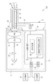
図1及び2に示すように、第1実施形態の内視鏡システム10は、被検体への照明光を発生する光源装置11と、光源装置11から発せられる光を導光して被検体の被観察領域に照明光を照射し、その反射光等を撮像する内視鏡装置12と、内視鏡装置12で得られた画像信号を画像処理するプロセッサ装置13と、画像処理によって得られた内視鏡画像等を表示する表示装置14と、キーボード等で構成される入力装置15とを備えている。
As shown in FIGS. 1 and 2, the
光源装置11は、図3に示すような青色〜赤色までのブロードな波長の光である白色光を発するキセノンランプ18を備えている。このキセノンランプ18から発せられる白色光は、集光レンズ(図示省略)を介して光ファイバ24に入射する。なお、キセノンランプの他、ハロゲンランプや白色LED(Light Emitting Diode)を用いてもよい。また、キセノンランプに光量制御部を接続し、この光量制御部によって白色光の光量を制御してもよい。
The
コンバイナ21は、光ファイバ24からの光を合波させる。合波した光は、分波器であるカプラ22によって2系統の光に分波される。分波された2系統の光は、ライトガイド28,29で伝送される。ライトガイド28,29は多数の光ファイバを束ねたバンドルファイバなどから構成される。なお、コンバイナ21及びカプラ22を用いずに、キセノンランプ18からの白色光を直接ライトガイド28,29に入れる構成としてもよい。
The
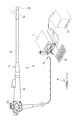
内視鏡装置12は電子内視鏡から構成され、内視鏡スコープ32と、ライトガイド28,29で伝送される2系統(2灯)の光を照射する照明部33と、被観察領域を撮像する1系統の撮像部34と、内視鏡スコープ32の先端部の湾曲操作や観察のための操作を行う操作部35と、内視鏡スコープ32と光源装置11及びプロセッサ装置13とを着脱自在に接続するコネクタ部36を備えている。
The
内視鏡スコープ32には、操作部35側から順に、軟性部38、湾曲部39、スコープ先端部40が設けられている。軟性部38は、可撓性を有しているため、内視鏡スコープ挿入時には被検体内で屈曲自在にすることができる。湾曲部39は、操作部35に配置されたアングルノブ35aの回動操作により湾曲自在に構成されている。この湾曲部39は、被検体の部位等に応じて、任意の方向、任意の角度に湾曲させることができるため、スコープ先端部40を所望の観察部位に向けることができる。
The
スコープ先端部40には照明部33と撮像部34が設けられている。撮像部34は、スコープ先端部40の略中心位置に、被写体領域からの反射光等を撮像する1つの観察窓42を備えている。照明部33は、撮像部34の両脇に設けられた2つの照明窓43,44を備えており、各照明窓43,44は、白色光を被観察領域に向けて照射する。
The
観察窓42の奥には、被検体の被観察領域の像光を取り込むための対物レンズ48が設けられている。さらにその奥には、対物レンズ48を経た光のうち特定の波長帯域の光を選択的に透過させ、且つ透過させる光の波長帯域を変更することができる波長可変素子50と、波長可変素子50を経た光を受光して被観察領域を撮像する撮像素子60とが設けられている。
In the back of the observation window 42, an
波長可変素子50はエタロンから構成され、図4に示すように、対物レンズ48と撮像素子60との光路L上に設けられた2枚の高反射光フィルタ51,52と、一方の高反射光フィルタ52を光路Lに沿って移動させる圧電アクチュエータ53とを備えている。波長可変素子50は、2枚の高反射光フィルタ51,52間の面間隔(エアギャップ)dを圧電アクチュエータ53によって変更することによって、白色光のうち特定波長を有する狭帯域光を分光する。
The wavelength
撮像素子60はCCD(Charge Coupled Device)やCMOS(Complementary Metal-Oxide Semiconductor)などのモノクロ撮像素子から構成され、波長可変素子からの光を受光面(撮像面)で受光し、受光した光を光電変換して撮像信号(アナログ信号)を出力する。撮像素子60から出力される撮像信号(アナログ信号)は、スコープケーブル67を通じてA/D変換器68に入力される。A/D変換器68は、撮像信号(アナログ信号)をその電圧レベルに対応する画像信号(デジタル信号)に変換する。変換後の画像信号は、コネクタ部36を介して、プロセッサ装置13の画像処理部73に入力される。
The
スコープ制御部70は波長可変素子50及び撮像素子60の制御を行う。第1実施形態では、図5に示すように、波長可変素子50は、スコープ制御部70の駆動制御によって、中心波長440nmの狭帯域光と、中心波長450nmの狭帯域光と、中心波長475nmの狭帯域光と、中心波長500nmの狭帯域光と、中心波長540nmの狭帯域光とを、1フレームの期間毎に順に分光する。そして、各狭帯域光が分光される毎に、撮像素子60は、スコープ制御部70の駆動制御によって、各狭帯域光を光電変換して得られる電荷を蓄積し、蓄積した電荷を読み出す。これら合計5フレーム分の駆動制御は、繰り返し行われる。
The
ここで、中心波長440nmの狭帯域光を撮像したときに得られる画像信号をS440と、中心波長450nmの狭帯域光を撮像したときに得られる画像信号をS450と、中心波長475nmの狭帯域光を撮像したときに得られる画像信号をS475と、中心波長500nmの狭帯域光を撮像したときに得られる画像信号をS500と、中心波長540nmの狭帯域光を撮像したときに得られる画像信号をS540とする。 Here, S440 is an image signal obtained when imaging narrow-band light having a center wavelength of 440 nm, S450 is an image signal obtained when imaging narrow-band light having a center wavelength of 450 nm, and narrow-band light having a center wavelength of 475 nm. S475 is an image signal obtained when an image is captured, S500 is an image signal obtained when an image of narrowband light having a center wavelength of 500 nm is imaged, and an image signal obtained when an image of narrowband light having a center wavelength of 540 nm is imaged. Let S540.
なお、図示はしていないが、内視鏡装置12における操作部35及び内視鏡スコープ32の内部には、組織採取用処置具等を挿入する鉗子チャンネルや、送気・送水用のチャンネル等、各種のチャンネルが設けられている。
Although not shown, a forceps channel for inserting a tissue collection treatment tool or the like, an air supply / water supply channel, or the like inside the
プロセッサ装置13は、制御部72と、画像処理部73と、記憶部74とを備えており、制御部72には表示装置14及び入力装置15が接続されている。制御部72は、画像処理部73、内視鏡装置12のスコープ制御部70、及び表示装置14の動作を制御する。画像処理部73は、内視鏡装置12から入力される画像信号を補正する信号補正部80と、補正された画像信号に基づいて、血中ヘモグロビンの酸素飽和度を画像化する酸素飽和度画像生成部81とを備えている。
The
信号補正部80は、各フレーム間における配光分布の違いによる信号分布の違いが無くなるように、画像信号を補正する。配光分布の違いは、各フレームで波長が異なる狭帯域光が照射されることにより生ずるものであり、照明及び撮像光学系による影響のため、画像中心が一番が少なく、画像周辺に向かうに従い徐々に大きくなることが分かっている。したがって、配光分布の違いによる信号分布の違いを補正せずにそのまま酸素飽和度画像の生成を行った場合には、酸素飽和度画像で表示される酸素飽和度の正確性は低下する可能性が高い。
The
そこで、第1実施形態では、酸素飽和度画像の生成に用いる画像信号S440、S475、S540のうちS440とS540について、酸素飽和度の情報が乗った低周波成分の信号を維持した状態で、中間波長のS475の信号分布に合わせるように補正する。S440の補正には、S440に近い波長の画像信号S450、S500の低周波成分L(S450)、L(S500)を用いる。これらL(S450)、L(S500)に基づき、以下の式により補正データC440を生成する。
C440=L(S500)−L(S450)+F440(d)
この式においてF440(d)は、画像中心からの距離dに依存する値であり、画像中心でC440を「0」にするためのオフセット値である。なお、L(S500)、L(S450)は画像信号S500、S450に所定サイズの平均値フィルタを掛け合わせることで得られる。
Accordingly, in the first embodiment, among the image signals S440, S475, and S540 used for generating the oxygen saturation image, the intermediate frequency signal S440 and S540 are maintained in a state where the low frequency component signal carrying the oxygen saturation information is maintained. Correction is made to match the signal distribution of wavelength S475. For the correction of S440, the low frequency components L (S450) and L (S500) of the image signals S450 and S500 having a wavelength close to that of S440 are used. Based on these L (S450) and L (S500), correction data C440 is generated by the following equation.
C440 = L (S500) −L (S450) + F440 (d)
In this equation, F440 (d) is a value depending on the distance d from the image center, and is an offset value for setting C440 to “0” at the image center. Note that L (S500) and L (S450) are obtained by multiplying the image signals S500 and S450 by an average value filter of a predetermined size.
補正データC440を求めたら、以下の式によりS440に補正データC440を足し合わせることにより、補正信号S´440を得る。
S´440=S440+C440
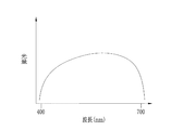
この式において、S440に加算される補正データC440自体は、酸化ヘモグロビン(HbO2)と還元ヘモグロビン(Hb)の吸光係数が同じである波長450nm、500nm(等吸収波長(図6参照))の画像信号S450、S500を元に作成していることから、補正後のS´440は、S440に乗っている可能性のある低周波の酸素飽和度の信号を消すことなく、中間波長のS475の信号分布に近づけた信号となっている。
When the correction data C440 is obtained, the correction signal S′440 is obtained by adding the correction data C440 to S440 according to the following equation.
S'440 = S440 + C440
In this equation, the correction data C440 itself added to S440 is an image signal of
一方、S540の補正には、S540の低周波成分L(S540)と、S540に近い波長の画像信号S500の低周波成分L(S500)を用いる。これらL(S540)、L(S500)に基づき、以下の式により補正データC540を生成する。
C540=L(S500)−L(S540)+F540(d)
この式においてF540(d)は、前記F440(d)と同様のオフセット値である。
On the other hand, for the correction of S540, the low frequency component L (S540) of S540 and the low frequency component L (S500) of the image signal S500 having a wavelength close to S540 are used. Based on L (S540) and L (S500), correction data C540 is generated by the following equation.
C540 = L (S500) -L (S540) + F540 (d)
In this equation, F540 (d) is the same offset value as F440 (d).
補正データC540を求めたら、以下の式によりS540に補正データC540を足し合わせることにより、補正信号S´540を得る。
S´540=S540+C540
このS´540は、中間波長のS475の信号分布に近づいた信号となっている。なお、上記式において、補正データC540は等吸収波長の画像信号に基づいて生成され、またS540自体も等吸収波長の画像であるので、S´540は酸素飽和度の変化によって信号値に変化は生じない。
When the correction data C540 is obtained, the correction signal S′540 is obtained by adding the correction data C540 to S540 according to the following equation.
S'540 = S540 + C540
This S′540 is a signal that is close to the signal distribution of the intermediate wavelength S475. In the above equation, the correction data C540 is generated based on the image signal of the isosbestic wavelength, and S540 itself is an image of the isosbestic wavelength, so that the signal value of S′540 changes due to the change in oxygen saturation. Does not occur.
酸素飽和度画像生成部は、補正後のS´440、S´540とS475に基づいて、酸素飽和度画像を生成する。酸素飽和度画像はRGBチャンネルからなる映像信号であり、RGBのチャンネルのそれぞれにS´440、S475、S´540が割り当てられる。生成された酸素飽和度画像は表示装置14に表示される。表示装置14に表示される酸素飽和度画像は、酸素飽和度に応じて色調が変化する。
The oxygen saturation image generation unit generates an oxygen saturation image based on the corrected S′440, S′540, and S475. The oxygen saturation image is a video signal composed of RGB channels, and S′440, S475, and S′540 are assigned to each of the RGB channels. The generated oxygen saturation image is displayed on the
以上のように、本発明では、酸素飽和度画像の生成に用いられる画像信号のうちS´440、S´540は、酸素飽和度の情報が乗った信号を維持した状態で、S475の信号分布に合うように補正されているため、各フレーム間で配光分布に違いがあったとしても、それにより酸素飽和度の情報(酸素飽和度に応じて変化する色調情報)が不正確に表示装置14に表示されることはない。 As described above, in the present invention, S ′ 440 and S ′ 540 among the image signals used for generating the oxygen saturation image maintain the signal carrying the oxygen saturation information and the signal distribution of S 475. Therefore, even if there is a difference in the light distribution between the frames, the oxygen saturation information (color information that changes according to the oxygen saturation) is displayed incorrectly. 14 is not displayed.
次に、本発明の作用を図7のフローチャートに沿って説明する。まず、波長可変素子50は、被検体からの反射光等から中心波長440nmの狭帯域光を分光する。分光された中心波長440nmの狭帯域光は、モノクロの撮像素子60で撮像される。これにより、画像信号S440が得られる。
Next, the operation of the present invention will be described with reference to the flowchart of FIG. First, the wavelength
同様にして、波長可変素子50によって、中心波長450nmの狭帯域光、中心波長475nmの狭帯域光、中心波長500nmの狭帯域光、中心波長540nmの狭帯域光を分光し、分光する毎に撮像素子60で撮像を行う。これにより、画像信号S450、画像信号S475、画像信号S500、画像信号S540が得られる。
Similarly, the wavelength
上記5種類の画像信号が得られたら、S440の信号補正を行うために、等吸収波長の画像信号S500とS450とを用いて補正データC440を生成する。この補正データC440を画像信号S440に加算することにより、画像信号S´440が得られる。S´440は、S440に乗っている可能性のある低周波の酸素飽和度の信号を維持した状態で、S475の信号分布に近づいた信号となっている。 When the five types of image signals are obtained, correction data C440 is generated using the image signals S500 and S450 of the equal absorption wavelength in order to perform the signal correction of S440. By adding the correction data C440 to the image signal S440, an image signal S′440 is obtained. S′440 is a signal approaching the signal distribution of S475 while maintaining a low-frequency oxygen saturation signal that may be on S440.
また、S540の信号補正を行うために、等吸収波長の画像信号S540とS500とを用いて補正データC540を生成する。この補正データC540を画像信号S540に加算することにより、画像信号S´540が得られる。S´540は、S475の信号分布に近づいた信号となっている。 Further, in order to perform the signal correction in S540, correction data C540 is generated using the image signals S540 and S500 having the equal absorption wavelength. By adding the correction data C540 to the image signal S540, an image signal S′540 is obtained. S′540 is a signal approaching the signal distribution of S475.
そして、補正後の画像信号S´440及びS´540と画像信号S475から酸素飽和度画像を生成し、生成した酸素飽和度画像を表示装置14に表示する。表示装置14に表示される酸素飽和度画像は、酸素飽和度の変化に応じて色調が変化する。
Then, an oxygen saturation image is generated from the corrected image signals S ′ 440 and S ′ 540 and the image signal S 475, and the generated oxygen saturation image is displayed on the
第2実施形態では、酸素飽和度画像の生成に、中心波長440nmの狭帯域光の画像信号S440と、中心波長475nmの狭帯域光の画像信号S475と、中心波長560nmの狭帯域光の画像信号S560を用い、画像信号の補正に、中心波長450nmの狭帯域光の画像信号S450と、中心波長500nmの狭帯域光の画像信号と、中心波長570nmの狭帯域光の画像信号S570を用いる。 In the second embodiment, for the generation of the oxygen saturation image, a narrowband light image signal S440 having a center wavelength of 440 nm, a narrowband light image signal S475 having a center wavelength of 475 nm, and a narrowband light image signal having a center wavelength of 560 nm are used. The image signal is corrected using a narrowband light image signal S450 having a center wavelength of 450 nm, a narrowband light image signal having a center wavelength of 500 nm, and a narrowband light image signal S570 having a center wavelength of 570 nm.
この第2実施形態は、酸素飽和度画像の生成及び画像信号の補正に用いる画像信号の種類が6に増える以外は、第1実施形態と同様である。したがって、図8に示すように、各狭帯域光は、1フレーム期間毎に、被検体からの反射光等を波長可変素子50で分光することにより生成され、また、各狭帯域光を分光する毎に撮像素子60によって撮像が行われる。
The second embodiment is the same as the first embodiment except that the number of image signals used for generating an oxygen saturation image and correcting an image signal is increased to six. Therefore, as shown in FIG. 8, each narrowband light is generated by splitting the reflected light or the like from the subject with the wavelength
画像信号の補正は、酸素飽和度画像の生成に用いられる画像信号S440、S475、S570のうちS440とS570に対して行う。S440とS570は、酸素飽和度の情報が乗った低周波成分の信号を維持した状態で、中間波長の画像信号S475の信号分布に合わせるように補正する。ここで、S440の信号補正は、第1実施形態と同様であるので、説明を省略する。 The correction of the image signal is performed on S440 and S570 among the image signals S440, S475, and S570 used for generating the oxygen saturation image. In S440 and S570, correction is performed so as to match the signal distribution of the image signal S475 of the intermediate wavelength while maintaining the signal of the low frequency component carrying the oxygen saturation information. Here, since the signal correction in S440 is the same as that in the first embodiment, the description thereof is omitted.
一方、S570の補正には、S440に近い波長の画像信号S570、S500の低周波成分L(S570)、L(S500)を用いる。これらL(S570)、L(S500)に基づき、以下の式により補正データC570を生成する。
C570=L(S500)−L(S570)+F570(d)
この式においてF570(d)は、第1実施形態で示したF440(d)、F540(d)と同様のオフセット値である。なお、L(S500)、L(S570)は画像信号S500、S570に所定サイズの平均値フィルタを掛け合わせることで得られる。
On the other hand, the low frequency components L (S570) and L (S500) of the image signals S570 and S500 having a wavelength close to that of S440 are used for the correction of S570. Based on these L (S570) and L (S500), correction data C570 is generated by the following equation.
C570 = L (S500) -L (S570) + F570 (d)
In this equation, F570 (d) is the same offset value as F440 (d) and F540 (d) shown in the first embodiment. Note that L (S500) and L (S570) are obtained by multiplying the image signals S500 and S570 by an average value filter of a predetermined size.
補正データC570を求めたら、以下の式によりS570に補正データC570を足し合わせることにより、補正信号S´570を得る。
S´570=S570+C570
この式において、S570に加算される補正データC570自体は、等吸収波長の500nm、570nm(図6参照)の画像信号S500、S570を元に作成していることから、補正後のS´570は、S570に乗っている可能性のある低周波の酸素飽和度の信号を消すことなく、中間波長のS475の信号分布に近づけた信号となっている。
When the correction data C570 is obtained, the correction signal S′570 is obtained by adding the correction data C570 to S570 according to the following equation.
S'570 = S570 + C570
In this equation, the correction data C570 itself added to S570 is created based on the image signals S500 and S570 having the equal absorption wavelengths of 500 nm and 570 nm (see FIG. 6). The signal is close to the signal distribution of S475 of the intermediate wavelength without erasing the low frequency oxygen saturation signal that may be on S570.
そして、S440とS570の補正が完了したら、補正後のS´440及びS´570とS475を用いて酸素飽和度画像を生成し、生成した酸素飽和度画像を表示装置14に表示する。
When the corrections in S440 and S570 are completed, an oxygen saturation image is generated using the corrected S′440 and S′570 and S475, and the generated oxygen saturation image is displayed on the
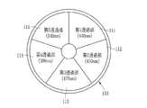
第3実施形態では、第1及び第2実施形態において狭帯域光の生成に用いた波長可変素子に代えて、図9に示すように、回転フィルタ110を用いて狭帯域光の生成を行う。回転フィルタ110は、内視鏡システム100内の光源装置11内において、キセノンランプ18と光ファイバ24との間に設けられている。回転フィルタ110は、周方向に沿って、キセノンランプ18からの白色光のうち特定波長の狭帯域光を透過させる透過部が複数設けられている。各透過部の透過波長範囲はそれぞれ異なっている。したがって、回転フィルタが回転することで、波長が異なる狭帯域光が順次透過する。透過した狭帯域光は、ライトガイド28,29を介して被検体内に照射される。そして、各狭帯域光が照射される毎に撮像素子60によて撮像が行われる。
In the third embodiment, instead of the wavelength tunable element used for generating the narrow band light in the first and second embodiments, as shown in FIG. 9, the narrow band light is generated using the
第1実施形態のように、5種類の狭帯域光(440nm、450nm、475nm、500nm、540nm)が必要な場合には、図10に示すように、回転フィルタ110に各狭帯域光のみを透過させる第1〜5透過部111〜115を設ける。また、第2実施形態のように、6種類の狭帯域光(440nm、450nm、475nm、500nm、560nm、570nm)が必要な場合には、回転フィルタ110に代えて、図11に示すような、各狭帯域光のみを透過させる第1〜6透過部121〜126が設けられた回転フィルタ120を用いる。
As in the first embodiment, when five types of narrowband light (440 nm, 450 nm, 475 nm, 500 nm, and 540 nm) are required, only the narrowband light is transmitted to the
第4実施形態では、波長可変素子を撮像素子の手前に設けた第1及び第2実施形態と異なり、図12に示すように、光源装置11内のキセノンランプ18と光ファイバ24の間に、波長可変素子50を設置する。したがって、第4実施形態の内視鏡システム200においては、キセノンランプ18からの白色光を波長可変素子50で分光し、その分光により得られる狭帯域光を被検体内に照射する。そして、各狭帯域光が分光される毎に、撮像素子60で撮像を行う。なお、第4実施形態は、光源装置11側で分光を行うこと以外は、第1実施形態と同様である。
In the fourth embodiment, unlike the first and second embodiments in which the wavelength variable element is provided in front of the imaging element, as shown in FIG. 12, between the
なお、上記実施形態では、波長可変素子としてエタロンを用いたが、その代わりに液晶チューナブルフィルタを用いてもよい。液晶チューナブルフィルタは、偏光フィルタ間に複屈折フィルタとネマティック液晶セルを挟んで構成され、液晶セルへの印加電圧を変更することで透過光の波長帯域を制御するものである。 In the above embodiment, an etalon is used as the wavelength tunable element, but a liquid crystal tunable filter may be used instead. The liquid crystal tunable filter is configured by sandwiching a birefringence filter and a nematic liquid crystal cell between polarizing filters, and controls a wavelength band of transmitted light by changing a voltage applied to the liquid crystal cell.
10,100,200 内視鏡システム
14 表示装置
50 波長可変素子
60 撮像素子
73 画像処理部
80 信号補正部
81 酸素飽和度画像生成部
10, 100, 200
Claims (10)
前記第2の画像信号を用いて得られる補正データに基づき、各狭帯域光間の配光分布の違いによる信号分布の違いが無くなるように、前記第1または第2の画像信号を補正する信号補正手段と、
補正後の第1及び第2の画像信号に基づいて、血中ヘモグロビンの酸素飽和度の分布を示す酸素飽和度画像を生成する酸素飽和度画像生成手段とを備えることを特徴とする内視鏡システム。 A first image signal corresponding to narrowband light having a wavelength having a difference in absorption coefficient between oxyhemoglobin and reduced hemoglobin, and oxyhemoglobin and reduced by imaging image light of a subject including narrowband light of a specific wavelength. Image signal acquisition means for acquiring a total of three or more second image signals corresponding to narrow-band light having wavelengths with the same absorption coefficient of hemoglobin;
Based on correction data obtained using the second image signal, a signal for correcting the first or second image signal so that a difference in signal distribution due to a difference in light distribution between the narrowband lights is eliminated. Correction means;
An endoscope comprising: an oxygen saturation image generating means for generating an oxygen saturation image indicating a distribution of oxygen saturation of blood hemoglobin based on the corrected first and second image signals system.
前記3つ以上の画像信号のうち、各狭帯域光の中で波長が中間にある狭帯域光に対応する中間画像信号以外の画像信号を、前記中間画像信号の信号分布に合わせるように補正することを特徴とする請求項1記載の内視鏡システム。 The signal correction means includes
Among the three or more image signals, the image signals other than the intermediate image signal corresponding to the narrowband light having an intermediate wavelength in each narrowband light are corrected so as to match the signal distribution of the intermediate image signal. The endoscope system according to claim 1.
前記第1の画像信号として、中心波長440nmの狭帯域光に対応する画像信号S440と、中心波長475nmの狭帯域光に対応する画像信号S475と、中心波長540nmの狭帯域光に対応する画像信号S540を取得するとともに、
前記第2の画像信号として、中心波長450nmの狭帯域光に対応する画像信号S450と、中心波長500nmの狭帯域光に対応する画像信号S500を取得し、
前記信号補正手段は、
画像信号S500と画像信号S450とを用いて得られる補正データC440に基づいて、画像信号S440を補正し、
画像信号S500と画像信号S540とを用いて得られる補正データC540に基づいて、画像信号S540を補正し、
前記酸素飽和度生成手段は、補正後の画像信号S´440、S´540と画像信号S475に基づいて酸素飽和度画像を生成することを特徴とする請求項1または2記載の内視鏡システム。 The image signal acquisition means includes
As the first image signal, an image signal S440 corresponding to narrowband light having a center wavelength of 440 nm, an image signal S475 corresponding to narrowband light having a center wavelength of 475 nm, and an image signal corresponding to narrowband light having a center wavelength of 540 nm. While acquiring S540
As the second image signal, an image signal S450 corresponding to narrowband light having a center wavelength of 450 nm and an image signal S500 corresponding to narrowband light having a center wavelength of 500 nm are acquired,
The signal correction means includes
Based on the correction data C440 obtained using the image signal S500 and the image signal S450, the image signal S440 is corrected,
Based on the correction data C540 obtained using the image signal S500 and the image signal S540, the image signal S540 is corrected,
The endoscope system according to claim 1 or 2, wherein the oxygen saturation generation unit generates an oxygen saturation image based on the corrected image signals S'440, S'540 and the image signal S475. .
前記第1の画像信号として、中心波長440nmの狭帯域光に対応する画像信号S440と、中心波長475nmの狭帯域光に対応する画像信号S475と、中心波長560nmの狭帯域光に対応する画像信号S560を取得するとともに、
前記第2の画像信号として、中心波長450nmの狭帯域光に対応する画像信号S450と、中心波長500nmの狭帯域光に対応する画像信号S500と、中心波長570nmの狭帯域光に対応する画像信号S570を取得し、
前記信号補正手段は、
画像信号S500と画像信号S450とを用いて得られる補正データC440に基づいて、画像信号S440を補正し、
画像信号S570と画像信号S500とを用いて得られる補正データC560に基づいて、画像信号S560を補正し、
前記酸素飽和度画像生成手段は、補正後の画像信号S´440、S´560と画像信号S475に基づいて酸素飽和度画像を生成することを特徴とする請求項1または2記載の内視鏡システム。 The image signal acquisition means includes
As the first image signal, an image signal S440 corresponding to narrowband light having a center wavelength of 440 nm, an image signal S475 corresponding to narrowband light having a center wavelength of 475 nm, and an image signal corresponding to narrowband light having a center wavelength of 560 nm. While acquiring S560,
As the second image signal, an image signal S450 corresponding to narrowband light having a center wavelength of 450 nm, an image signal S500 corresponding to narrowband light having a center wavelength of 500 nm, and an image signal corresponding to narrowband light having a center wavelength of 570 nm. Get S570,
The signal correction means includes
Based on the correction data C440 obtained using the image signal S500 and the image signal S450, the image signal S440 is corrected,
Based on the correction data C560 obtained using the image signal S570 and the image signal S500, the image signal S560 is corrected,
The endoscope according to claim 1 or 2, wherein the oxygen saturation image generation means generates an oxygen saturation image based on the corrected image signals S'440, S'560 and the image signal S475. system.
前記第2の画像信号を用いて得られる補正データに基づき、各狭帯域光間の配光分布の違いによる信号分布の違いが無くなるように、前記第1または第2の画像信号を補正し、
補正後の第1及び第2の画像信号に基づいて、血中ヘモグロビンの酸素飽和度の分布を示す酸素飽和度画像を生成することを特徴とする画像生成方法。 A first image signal corresponding to narrowband light having a wavelength having a difference in absorption coefficient between oxyhemoglobin and reduced hemoglobin and oxidation by imaging image light of a subject including narrowband light of a specific wavelength on the imaging surface Obtaining a total of three or more second image signals corresponding to narrow-band light having wavelengths with the same absorption coefficient of hemoglobin and reduced hemoglobin,
Based on the correction data obtained using the second image signal, the first or second image signal is corrected so that there is no difference in signal distribution due to the difference in light distribution between each narrowband light,
An image generation method characterized by generating an oxygen saturation image showing a distribution of oxygen saturation of blood hemoglobin based on the corrected first and second image signals.
Priority Applications (1)
| Application Number | Priority Date | Filing Date | Title |
|---|---|---|---|
| JP2011004194A JP2012143398A (en) | 2011-01-12 | 2011-01-12 | Endoscope system and image generating method |
Applications Claiming Priority (1)
| Application Number | Priority Date | Filing Date | Title |
|---|---|---|---|
| JP2011004194A JP2012143398A (en) | 2011-01-12 | 2011-01-12 | Endoscope system and image generating method |
Publications (1)
| Publication Number | Publication Date |
|---|---|
| JP2012143398A true JP2012143398A (en) | 2012-08-02 |
Family
ID=46787612
Family Applications (1)
| Application Number | Title | Priority Date | Filing Date |
|---|---|---|---|
| JP2011004194A Pending JP2012143398A (en) | 2011-01-12 | 2011-01-12 | Endoscope system and image generating method |
Country Status (1)
| Country | Link |
|---|---|
| JP (1) | JP2012143398A (en) |
Cited By (4)
| Publication number | Priority date | Publication date | Assignee | Title |
|---|---|---|---|---|
| CN103654687A (en) * | 2012-09-21 | 2014-03-26 | 富士胶片株式会社 | Endoscope system, light source device for endoscope and manufacturing method of endoscope images |
| EP2912991A1 (en) * | 2014-02-27 | 2015-09-02 | FUJIFILM Corporation | Endoscope system, endoscope system processor device, operation method for endoscope system, and operation method for endoscope system processor device |
| WO2016158276A1 (en) * | 2015-04-02 | 2016-10-06 | 富士フイルム株式会社 | Processor device and method for operating same, and endoscopic system and method for operating same |
| WO2024034839A1 (en) * | 2022-08-09 | 2024-02-15 | 삼성전자 주식회사 | Electronic device for measuring oxygen saturation and method for controlling same |
-
2011
- 2011-01-12 JP JP2011004194A patent/JP2012143398A/en active Pending
Cited By (8)
| Publication number | Priority date | Publication date | Assignee | Title |
|---|---|---|---|---|
| CN103654687A (en) * | 2012-09-21 | 2014-03-26 | 富士胶片株式会社 | Endoscope system, light source device for endoscope and manufacturing method of endoscope images |
| JP2014061152A (en) * | 2012-09-21 | 2014-04-10 | Fujifilm Corp | Endoscope system, light source device for endoscope, and method for creating endoscope image |
| EP2912991A1 (en) * | 2014-02-27 | 2015-09-02 | FUJIFILM Corporation | Endoscope system, endoscope system processor device, operation method for endoscope system, and operation method for endoscope system processor device |
| US9675287B2 (en) | 2014-02-27 | 2017-06-13 | Fujifilm Corporation | Endoscope system, endoscope system processor device, operation method for endoscope system, and operation method for endoscope system processor device |
| WO2016158276A1 (en) * | 2015-04-02 | 2016-10-06 | 富士フイルム株式会社 | Processor device and method for operating same, and endoscopic system and method for operating same |
| JPWO2016158276A1 (en) * | 2015-04-02 | 2018-01-25 | 富士フイルム株式会社 | Processor device and endoscope system |
| US10264955B2 (en) | 2015-04-02 | 2019-04-23 | Fujifilm Corporation | Processor device and method for operating same, and endoscopic system and method for operating same |
| WO2024034839A1 (en) * | 2022-08-09 | 2024-02-15 | 삼성전자 주식회사 | Electronic device for measuring oxygen saturation and method for controlling same |
Similar Documents
| Publication | Publication Date | Title |
|---|---|---|
| JP5457247B2 (en) | Electronic endoscope system, processor device for electronic endoscope, and method for operating electronic endoscope system | |
| JP5303012B2 (en) | Endoscope system, processor device for endoscope system, and method for operating endoscope system | |
| JP5496852B2 (en) | Electronic endoscope system, processor device for electronic endoscope system, and method for operating electronic endoscope system | |
| JP5191090B2 (en) | Endoscope device | |
| JP5451802B2 (en) | Electronic endoscope system and calibration method for electronic endoscope system | |
| JP5231511B2 (en) | Endoscopic diagnosis device | |
| JP5466182B2 (en) | Endoscope system and method for operating endoscope system | |
| JP5306447B2 (en) | Transmittance adjusting device, observation device, and observation system | |
| JP5670264B2 (en) | Endoscope system and method for operating endoscope system | |
| US8996087B2 (en) | Blood information measuring method and apparatus | |
| JP5431252B2 (en) | Electronic endoscope system, processor device for electronic endoscope, and method for operating electronic endoscope system | |
| US20140100427A1 (en) | Endoscope system, processor device thereof, and image display method | |
| US11497390B2 (en) | Endoscope system, method of generating endoscope image, and processor | |
| JP5752423B2 (en) | Spectroscopic measurement system and method of operating the spectral measurement system | |
| JP6100674B2 (en) | Endoscope light source device and endoscope system | |
| EP2666403B1 (en) | Endoscope system and processor device thereof | |
| JP5780653B2 (en) | Light source device and endoscope system | |
| JP2012143398A (en) | Endoscope system and image generating method | |
| US20190350448A1 (en) | Endoscope system | |
| JP2009142415A (en) | Endoscopic system | |
| JP5371702B2 (en) | Electronic endoscope system, processor device for electronic endoscope, and method for operating electronic endoscope system | |
| JP2012125402A (en) | Endoscope system, processor device thereof, and method of obtaining function information | |
| JP6325707B2 (en) | Endoscope light source device and endoscope system | |
| JP4712505B2 (en) | Electronic endoscope device | |
| JP5483522B2 (en) | Image acquisition device |