以下、添付図面を参照しながら本発明に係る油圧駆動装置の好適な実施の形態について詳細に説明する。
Hereinafter, preferred embodiments of a hydraulic drive device according to the present invention will be described in detail with reference to the accompanying drawings.
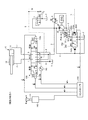
(実施の形態1)
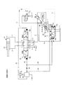
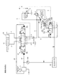
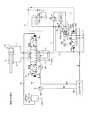
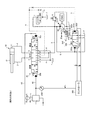
図1は、本発明の実施の形態1であるロードセンシング方式の油圧駆動装置の油圧回路図を示したものである。ここで例示する油圧駆動装置は、油圧シリンダ10と、油圧シリンダ10に対して油圧ポンプ20からの油の供給制御を行う方向制御弁30とを備え、操作レバー41を介して方向制御弁30を動作させることにより、油圧シリンダ10の駆動を制御するものである。尚、図には示していないが、この油圧駆動装置には、油圧シリンダ10以外の油圧アクチュエータを駆動するための方向制御弁、操作レバー及びパイロット操作弁が設けてある。
(Embodiment 1)
FIG. 1 shows a hydraulic circuit diagram of a load sensing type hydraulic drive apparatus according to Embodiment 1 of the present invention. The hydraulic drive apparatus exemplified here includes a hydraulic cylinder 10 and a directional control valve 30 that controls supply of oil from the hydraulic pump 20 to the hydraulic cylinder 10, and the directional control valve 30 is provided via an operation lever 41. By operating, the drive of the hydraulic cylinder 10 is controlled. Although not shown in the figure, this hydraulic drive device is provided with a direction control valve, an operation lever, and a pilot operation valve for driving a hydraulic actuator other than the hydraulic cylinder 10.
方向制御弁30は、操作レバー41の操作に伴ってパイロット操作弁40から出力される操作パイロット圧により動作し、2つのアクチュエータポートa,bに対する供給ポートcとドレンポートdとの接続態様を選択的に切り替えるものである。具体的には、図1に示す中立位置にある場合、方向制御弁30は、2つのアクチュエータポートa,bと、供給ポートc及びドレンポートdとの間を遮断した状態に維持する。この状態から図1中の右方に動作して伸長位置に切り替わると、一方のアクチュエータポートbと供給ポートcとの間を接続するとともに、他方のアクチュエータポートaとドレンポートdとの間を接続する。中立位置から図1中の左方に動作して縮退位置に切り替わると、一方のアクチュエータポートbとドレンポートdとの間を接続するとともに、他方のアクチュエータポートaと供給ポートcとの間を接続した状態となる。
The direction control valve 30 is operated by the operation pilot pressure output from the pilot operation valve 40 in accordance with the operation of the operation lever 41, and selects the connection mode between the supply port c and the drain port d for the two actuator ports a and b. Is to switch automatically. Specifically, when in the neutral position shown in FIG. 1, the direction control valve 30 maintains a state in which the two actuator ports a and b are disconnected from the supply port c and the drain port d. When operating from this state to the right in FIG. 1 and switching to the extended position, one actuator port b and the supply port c are connected, and the other actuator port a and the drain port d are connected. To do. When moving from the neutral position to the left in FIG. 1 and switching to the retracted position, one actuator port b and the drain port d are connected, and the other actuator port a and the supply port c are connected. It will be in the state.
方向制御弁30の一方のアクチュエータポートbには、ボトム油路1を通じて油圧シリンダ10のボトム室11が接続してあり、他方のアクチュエータポートaには、ヘッド油路2を通じて油圧シリンダ10のヘッド室12が接続してある。方向制御弁30の供給ポートcには、油圧ポンプ20の吐出口との間を接続する供給油路3が接続してあり、方向制御弁30のドレンポートdには、油タンクTとの間を接続するドレン油路4が接続してある。
The bottom chamber 11 of the hydraulic cylinder 10 is connected to one actuator port b of the direction control valve 30 through the bottom oil passage 1, and the head chamber of the hydraulic cylinder 10 is connected to the other actuator port a through the head oil passage 2. 12 is connected. A supply oil passage 3 is connected to the supply port c of the directional control valve 30 and connected to the discharge port of the hydraulic pump 20. The drain port d of the directional control valve 30 is connected to the oil tank T. A drain oil passage 4 is connected.
また、方向制御弁30には、負荷圧出力ポートeが設けてある。負荷圧出力ポートeは、供給ポートcを通じて油圧シリンダ10のヘッド室12に油が供給されている間、並びに供給ポートcを通じて油圧シリンダ10のボトム室11に油が供給されている間、それぞれ油の供給圧を負荷圧として出力するものである。
The direction control valve 30 is provided with a load pressure output port e. The load pressure output port e is oil while oil is supplied to the head chamber 12 of the hydraulic cylinder 10 through the supply port c and while oil is supplied to the bottom chamber 11 of the hydraulic cylinder 10 through the supply port c. The supply pressure is output as a load pressure.
パイロット操作弁40は、操作レバー41のレバー中立位置からの操作量に応じたパイロット圧を、操作レバー41の操作方向に応じたパイロット油路42,43を通じて方向制御弁30の圧力室30a,30bに出力するものである。
The pilot operation valve 40 applies a pilot pressure corresponding to the operation amount from the lever neutral position of the operation lever 41 to the pressure chambers 30a and 30b of the direction control valve 30 through the pilot oil passages 42 and 43 corresponding to the operation direction of the operation lever 41. Is output.
本実施の形態1では、操作レバー41をレバー中立位置から図1中の矢印A方向に操作した場合、伸長側パイロット油路42を通じてパイロット圧が出力され、方向制御弁30が中立位置から伸長位置に切り替わる。方向制御弁30が伸長位置に切り替わると、油圧シリンダ10のボトム室11に接続されたボトム油路1が、方向制御弁30のアクチュエータポートb及び供給ポートcを介して供給油路3に接続されるとともに、ヘッド室12に接続されたヘッド油路2が方向制御弁30のアクチュエータポートa及びドレンポートdを介してドレン油路4に接続される。
In the first embodiment, when the operation lever 41 is operated from the lever neutral position in the direction of arrow A in FIG. 1, pilot pressure is output through the extension-side pilot oil passage 42, and the direction control valve 30 is extended from the neutral position to the extension position. Switch to When the directional control valve 30 is switched to the extended position, the bottom oil passage 1 connected to the bottom chamber 11 of the hydraulic cylinder 10 is connected to the supply oil passage 3 via the actuator port b and the supply port c of the directional control valve 30. At the same time, the head oil passage 2 connected to the head chamber 12 is connected to the drain oil passage 4 via the actuator port a and the drain port d of the direction control valve 30.
これとは逆に、操作レバー41がレバー中立位置から図1中の矢印B方向に操作された場合には、縮退側パイロット油路43を通じてパイロット圧が出力され、方向制御弁30が中立位置から縮退位置に切り替わる。方向制御弁30が縮退位置に切り替わると、油圧シリンダ10のボトム室11に接続されたボトム油路1が方向制御弁30のアクチュエータポートb及びドレンポートdを介してドレン油路4に接続されるとともに、ヘッド室12に接続されたヘッド油路2が方向制御弁30のアクチュエータポートa及び供給ポートcを介して供給油路3に接続されることになる。
On the contrary, when the operation lever 41 is operated in the direction of arrow B in FIG. 1 from the lever neutral position, pilot pressure is output through the degenerate side pilot oil passage 43 and the direction control valve 30 is moved from the neutral position. Switch to the degenerate position. When the direction control valve 30 is switched to the retracted position, the bottom oil passage 1 connected to the bottom chamber 11 of the hydraulic cylinder 10 is connected to the drain oil passage 4 via the actuator port b and the drain port d of the direction control valve 30. At the same time, the head oil passage 2 connected to the head chamber 12 is connected to the supply oil passage 3 via the actuator port a and the supply port c of the direction control valve 30.
図1からも明らかなように、伸長側パイロット油路42には、その中間部に絞り44が設けてある。この絞り44は、操作レバー41が操作された場合に伸長側パイロット油路42に出力されるパイロット圧の変化量が大きいほど、その前後に大きな差圧を生じさせるための固定絞りである。
As is clear from FIG. 1, the extension-side pilot oil passage 42 is provided with a throttle 44 at an intermediate portion thereof. The throttle 44 is a fixed throttle for generating a larger differential pressure before and after the change amount of the pilot pressure output to the extension pilot oil passage 42 when the operation lever 41 is operated.
油圧ポンプ20は、建設機械に搭載されたエンジンENGによって駆動される可変容量型のもので、ポンプ容量制御ユニット50を備えている。ポンプ容量制御ユニット50は、油圧ポンプ20の斜板角を変更するポンプ容量制御シリンダ51と、ポンプ容量制御シリンダ51に対する油の供給制御を行うポンプ容量制御弁52とを備えて構成したものである。
The hydraulic pump 20 is a variable displacement type driven by an engine ENG mounted on a construction machine, and includes a pump displacement control unit 50. The pump capacity control unit 50 includes a pump capacity control cylinder 51 that changes the swash plate angle of the hydraulic pump 20 and a pump capacity control valve 52 that controls supply of oil to the pump capacity control cylinder 51. .
ポンプ容量制御シリンダ51は、ヘッド室51aに復帰バネ51bを内蔵した油圧シリンダであり、ピストンロッド51cが油圧ポンプ20の斜板21に連結してある。本実施の形態1では、ボトム室51dに油を供給した場合に油圧ポンプ20の容量を減少させる方向に斜板21を駆動する一方、ボトム室51dの油を排出した場合に油圧ポンプ20の容量を増大させる方向に斜板21を駆動するようにポンプ容量制御シリンダ51のピストンロッド51cと斜板21との間を連結している。
The pump capacity control cylinder 51 is a hydraulic cylinder in which a return spring 51b is built in a head chamber 51a, and a piston rod 51c is connected to the swash plate 21 of the hydraulic pump 20. In the first embodiment, when oil is supplied to the bottom chamber 51d, the swash plate 21 is driven in a direction to decrease the capacity of the hydraulic pump 20, while the capacity of the hydraulic pump 20 is discharged when the oil in the bottom chamber 51d is discharged. The piston rod 51c of the pump displacement control cylinder 51 and the swash plate 21 are connected so as to drive the swash plate 21 in the direction of increasing the swash plate 21.
ポンプ容量制御弁52は、油圧ポンプ20の吐出圧と、方向制御弁30の負荷圧出力ポートeに出力される油圧シリンダ10の負荷圧との差圧に応じて切り替え動作するものである。具体的に説明すると、ポンプ容量制御弁52は、ポンプ容量制御シリンダ51のボトム室51dをタンク圧とする第1位置と、ポンプ容量制御シリンダ51のボトム室51dに油を供給する第2位置とを備えている。ポンプ容量制御弁52の一方の端部には、ポンプ容量制御弁52が第1位置となる方向に向けて押圧する負荷圧力室52aが設けてあり、他方の端部にはポンプ容量制御弁52が第2位置となる方向に向けて押圧する吐出圧力室52bが設けてある。負荷圧力室52aには、方向制御弁30の負荷圧出力ポートeとの間を接続する負荷圧出力油路5が接続してあり、吐出圧力室52bには、油圧ポンプ20の供給油路3から分岐した吐出圧力出力油路6が接続してある。
The pump displacement control valve 52 performs a switching operation according to a differential pressure between the discharge pressure of the hydraulic pump 20 and the load pressure of the hydraulic cylinder 10 output to the load pressure output port e of the direction control valve 30. More specifically, the pump displacement control valve 52 has a first position where the tank pressure is the bottom chamber 51d of the pump displacement control cylinder 51, and a second position where oil is supplied to the bottom chamber 51d of the pump displacement control cylinder 51. It has. A load pressure chamber 52a is provided at one end of the pump displacement control valve 52 to press the pump displacement control valve 52 in the direction toward the first position, and the pump displacement control valve 52 is disposed at the other end. Is provided with a discharge pressure chamber 52b that presses in the direction toward the second position. The load pressure chamber 52a is connected to a load pressure output oil passage 5 that connects to the load pressure output port e of the direction control valve 30, and the discharge pressure chamber 52b is connected to the supply oil passage 3 of the hydraulic pump 20. A discharge pressure output oil passage 6 branched from is connected.
このポンプ容量制御弁52は、油圧ポンプ20の吐出圧が、油圧シリンダ10の負荷圧+設定バネ52cの押圧力を下回ると、図1に示した第1位置に配置された状態を維持し、ポンプ容量制御シリンダ51のボトム室51dをタンク圧として油圧ポンプ20の容量を増大させるように機能する。一方、ポンプ容量制御弁52は、油圧ポンプ20の吐出圧が、油圧シリンダ10の負荷圧+設定バネ52cの押圧力を上回ると、第2位置に切り替わり、ポンプ容量制御シリンダ51のボトム室51dに油を供給することにより、油圧ポンプ20の容量を減少させるように機能する。
When the discharge pressure of the hydraulic pump 20 falls below the load pressure of the hydraulic cylinder 10 + the pressing force of the setting spring 52c, the pump displacement control valve 52 maintains the state of being disposed at the first position shown in FIG. The bottom chamber 51d of the pump capacity control cylinder 51 functions as a tank pressure to increase the capacity of the hydraulic pump 20. On the other hand, when the discharge pressure of the hydraulic pump 20 exceeds the load pressure of the hydraulic cylinder 10 + the pressing force of the setting spring 52c, the pump capacity control valve 52 switches to the second position and enters the bottom chamber 51d of the pump capacity control cylinder 51. By supplying oil, it functions to reduce the capacity of the hydraulic pump 20.
また、ポンプ容量制御弁52には、両端部にそれぞれアシスト圧力室52d,52eが設けてある。アシスト圧力室52d,52eは、ポンプ容量制御弁52の動作をアシストするための圧力を付与するもので、伸長側パイロット油路42のパイロット圧を供給する個別のアシスト油路45,46が接続してある。一方のアシスト油路45は、伸長側パイロット油路42においてパイロット操作弁40と絞り44との間に位置する部分と、負荷圧力室52aに隣設したアシスト圧力室52dとの間を接続するように設けてある。他方のアシスト油路46は、伸長側パイロット油路42において方向制御弁30と絞り44との間に位置する部分と、吐出圧力室52bに隣設したアシスト圧力室52eとの間を接続するように設けてある。
The pump displacement control valve 52 is provided with assist pressure chambers 52d and 52e at both ends. The assist pressure chambers 52d and 52e apply pressure for assisting the operation of the pump displacement control valve 52, and the individual assist oil passages 45 and 46 for supplying the pilot pressure of the extension-side pilot oil passage 42 are connected. It is. One assist oil passage 45 connects a portion of the extension-side pilot oil passage 42 positioned between the pilot operation valve 40 and the throttle 44 and an assist pressure chamber 52d adjacent to the load pressure chamber 52a. Is provided. The other assist oil passage 46 connects a portion of the extension pilot oil passage 42 located between the direction control valve 30 and the throttle 44 and an assist pressure chamber 52e adjacent to the discharge pressure chamber 52b. Is provided.
尚、図1中の符号7は油圧ポンプ20の吐出圧と油圧シリンダ10の負荷圧とのバランスによって切り替え動作するアンロード弁、符号8は油圧ポンプ20の吐出圧に基づいて動作するリリーフ弁である。
Reference numeral 7 in FIG. 1 is an unload valve that switches according to the balance between the discharge pressure of the hydraulic pump 20 and the load pressure of the hydraulic cylinder 10, and reference numeral 8 is a relief valve that operates based on the discharge pressure of the hydraulic pump 20. is there.
以下、上記のように構成した油圧駆動装置の作用について説明する。操作レバー41が図1に示すレバー中立位置にある場合には、方向制御弁30が図1に示す中立位置に維持されており、2つのアクチュエータポートa,bと、供給ポートc及びドレンポートdとの間が遮断された状態にある。この状態においては、油圧ポンプ20から吐出された油がアンロード弁7のバネ7aに対抗する圧力まで上昇し、アンロード弁7が開放するため油タンクTへと排出される。これにより、油圧ポンプ20の吐出圧力がアンロード弁7の設定圧力となり、この圧力が吐出圧力出力油路6を通じて吐出圧力室52bに加えられる。一方、負荷圧出力油路5を通じて負荷圧力室52aに加えられる圧力はゼロとなる。これらの結果、ポンプ容量制御弁52が第2位置となり、ポンプ容量制御シリンダ51のボトム室51dに油が供給され、油圧ポンプ20の容量が最小の状態に設定される。
Hereinafter, the operation of the hydraulic drive apparatus configured as described above will be described. When the operation lever 41 is in the lever neutral position shown in FIG. 1, the direction control valve 30 is maintained in the neutral position shown in FIG. 1, and the two actuator ports a and b, the supply port c, and the drain port d Is in a state of being interrupted. In this state, the oil discharged from the hydraulic pump 20 rises to a pressure that opposes the spring 7a of the unload valve 7, and is discharged to the oil tank T because the unload valve 7 is opened. Thereby, the discharge pressure of the hydraulic pump 20 becomes the set pressure of the unload valve 7, and this pressure is applied to the discharge pressure chamber 52 b through the discharge pressure output oil passage 6. On the other hand, the pressure applied to the load pressure chamber 52a through the load pressure output oil passage 5 becomes zero. As a result, the pump displacement control valve 52 is in the second position, oil is supplied to the bottom chamber 51d of the pump displacement control cylinder 51, and the displacement of the hydraulic pump 20 is set to the minimum state.
この状態から油圧シリンダ10を伸長動作させるべく操作レバー41を図1中の矢印A方向に操作すると、パイロット操作弁40から伸長側パイロット油路42を通じて方向制御弁30にパイロット圧が供給され、方向制御弁30が伸長位置に切り替わる。この結果、油圧シリンダ10のボトム室11に接続されたアクチュエータポートbと供給ポートcとの間が接続されるとともに、ヘッド室12に接続されたアクチュエータポートaとドレンポートdとの間が接続され、油圧ポンプ20から吐出された油によって油圧シリンダ10が伸長動作することになる。
When the operation lever 41 is operated in the direction of arrow A in FIG. 1 to extend the hydraulic cylinder 10 from this state, the pilot pressure is supplied from the pilot operation valve 40 to the direction control valve 30 through the extension-side pilot oil passage 42. The control valve 30 is switched to the extended position. As a result, the actuator port b and the supply port c connected to the bottom chamber 11 of the hydraulic cylinder 10 are connected, and the actuator port a and the drain port d connected to the head chamber 12 are connected. The hydraulic cylinder 10 is extended by the oil discharged from the hydraulic pump 20.
油圧シリンダ10に油が供給されると、負荷圧が負荷圧出力ポートeから負荷圧出力油路5に出力されることになり、アンロード弁7が閉じる。さらに、負荷圧力室52aに作用する負荷圧によってポンプ容量制御弁52が第2位置から第1位置となる方向に動作し、ポンプ容量制御シリンダ51のボトム室51dが減圧されて、油圧ポンプ20の容量が増大する。以降、負荷圧力室52aに導かれた油圧シリンダ10の負荷圧と、吐出圧力室52bに導かれた油圧ポンプ20の吐出圧力との差圧に応じてポンプ容量制御弁52が適宜動作し、油圧ポンプ20が油圧シリンダ10の負荷圧と油圧ポンプ20の吐出圧力との差圧に応じた容量に制御される。
When oil is supplied to the hydraulic cylinder 10, the load pressure is output from the load pressure output port e to the load pressure output oil passage 5, and the unload valve 7 is closed. Further, the pump capacity control valve 52 operates in the direction from the second position to the first position by the load pressure acting on the load pressure chamber 52a, the bottom chamber 51d of the pump capacity control cylinder 51 is depressurized, and the hydraulic pump 20 Capacity increases. Thereafter, the pump capacity control valve 52 operates appropriately according to the differential pressure between the load pressure of the hydraulic cylinder 10 guided to the load pressure chamber 52a and the discharge pressure of the hydraulic pump 20 guided to the discharge pressure chamber 52b. The pump 20 is controlled to have a capacity corresponding to the differential pressure between the load pressure of the hydraulic cylinder 10 and the discharge pressure of the hydraulic pump 20.
ここで、ポンプ容量制御弁52を油圧ポンプ20の吐出圧と油圧シリンダ10の負荷圧との差圧によってのみ動作させるようにした場合には、図3のタイミングチャートに示すように、操作レバー41を操作してから油圧ポンプ20の容量が増減するまでに、上述した工程を経る必要があり、油圧シリンダ10の動作に影響を与える恐れがある。
Here, when the pump displacement control valve 52 is operated only by the differential pressure between the discharge pressure of the hydraulic pump 20 and the load pressure of the hydraulic cylinder 10, as shown in the timing chart of FIG. It is necessary to go through the above-described steps from when the is operated to when the capacity of the hydraulic pump 20 increases or decreases, which may affect the operation of the hydraulic cylinder 10.
すなわち、操作レバー41が矢印A方向(図1参照)に操作された時点(図3(a)のt1)から、パイロット操作弁40のパイロット圧が出力され(図3(b))、油圧シリンダ10の負荷圧が上昇して油圧ポンプ20の吐出圧力との差圧が小さくなる時点(図3(c)のt2)までに比較的大きなタイムラグを生じるため、ポンプ容量制御弁52が第1位置に向けて移動を開始して、油圧ポンプ20から吐出される油の流量が増大するまでに比較的長い時間を要する(図3(d)及び図3(e))。ここで、図3(d)に示したポンプ容量制御弁52に働く力は、図1中の右向きに作用する力を正として記載してあり、油圧ポンプ20の吐出圧力と油圧シリンダ10の負荷圧との差圧による力+設定バネ52cの押圧力<0となった時点(図3(d)中のt3)から、図3(e)のt3に示すように、油圧ポンプ20の容量が増加する。従って、図3(f)に示すように、操作レバー41の操作量を増加させた時点t1から油圧シリンダ10の速度の上昇が始まる時点t3までの時間も長くなる。特に、建設機械に適用される油圧シリンダ10は、大型に構成されたものが多いため、伸長するまでに大流量の油が必要となる。
That is, the pilot pressure of the pilot operation valve 40 is output (FIG. 3 (b)) from the time (t 1 in FIG. 3 (a)) when the operation lever 41 is operated in the direction of arrow A (see FIG. 1). Since a relatively large time lag occurs until the time when the load pressure of the cylinder 10 increases and the pressure difference from the discharge pressure of the hydraulic pump 20 decreases (t 2 in FIG. 3C), the pump displacement control valve 52 A relatively long time is required until the flow rate of the oil discharged from the hydraulic pump 20 increases after starting to move toward the first position (FIGS. 3D and 3E). Here, the force acting on the pump displacement control valve 52 shown in FIG. 3D is described with the force acting rightward in FIG. 1 as positive, and the discharge pressure of the hydraulic pump 20 and the load of the hydraulic cylinder 10 are described. from the pressing force of the force + setting spring 52c by the pressure difference between the pressure <0 when the time (t 3 in FIG. 3 (d)), as shown in t 3 in FIG. 3 (e), the hydraulic pump 20 Capacity increases. Accordingly, as shown in FIG. 3 (f), also it increases the time from time t 1 to the operation amount increased of the operation lever 41 to the time t 3 when the increase in the speed of the hydraulic cylinder 10 begins. In particular, since many hydraulic cylinders 10 that are applied to construction machines are configured to be large, a large amount of oil is required before they are extended.
同様に、操作レバー41がレバー中立位置へ向けて矢印B方向(図1参照)に操作された時点(図3(a)のt4)から、パイロット操作弁40のパイロット圧が減少し(図3(b))、油圧シリンダ10の負荷圧が下降して油圧ポンプ20の吐出圧力との差圧が大きくなる時点(図3(c)のt5)までに比較的大きなタイムラグが生じるため、ポンプ容量制御弁52が第2位置に向けて移動を開始して、油圧ポンプ20から吐出される油の流量が減少するまでに比較的長い時間を要する(図3(d)及び図3(e))。これにより、図3(f)に示すように、操作レバー41の操作量を減少させた時点から油圧シリンダ10の速度の低下が始まるまでの時間も長くなる(図3(f)のt4〜t5)。
Similarly, the pilot pressure of the pilot operation valve 40 decreases from the time (t 4 in FIG. 3A) when the operation lever 41 is operated in the arrow B direction (see FIG. 1) toward the lever neutral position (see FIG. 1). 3 (b)), a relatively large time lag occurs until the time point when the load pressure of the hydraulic cylinder 10 decreases and the pressure difference from the discharge pressure of the hydraulic pump 20 increases (t 5 in FIG. 3C). It takes a relatively long time until the pump displacement control valve 52 starts moving toward the second position and the flow rate of the oil discharged from the hydraulic pump 20 decreases (FIGS. 3D and 3E). )). Thus, as shown in FIG. 3 (f), t 4 ~ of time from the time of reducing the operation amount of the operation lever 41 to decrease the speed of the hydraulic cylinder 10 begins becomes long (Fig. 3 (f) t 5).
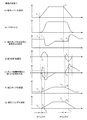
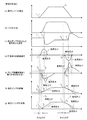
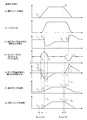
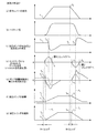
こうした操作レバー41と油圧シリンダ10との間の動作のタイムラグは、操作者に対して違和感を与えることになる。しかしながら、上述した油圧駆動装置では、伸長側パイロット油路42に絞り44を設け、かつこの絞り44の前後の圧力をそれぞれポンプ容量制御弁52に設けたアシスト圧力室52d,52eに作用させるようにしている。この絞り44の前後差圧は、操作レバー41を操作する際の変化量が大きいほど大きなものとなる。従って、操作レバー41を素早く操作した場合、絞り44の前後に生じる圧力差も大きなものとなり、図2のタイミングチャートに示すように、ポンプ容量制御弁52を迅速に動作させることができる。
Such a time lag of the operation between the operation lever 41 and the hydraulic cylinder 10 makes the operator feel uncomfortable. However, in the hydraulic drive device described above, a throttle 44 is provided in the extension-side pilot oil passage 42 and the pressure before and after the throttle 44 is applied to the assist pressure chambers 52d and 52e provided in the pump capacity control valve 52, respectively. ing. The front-rear differential pressure of the diaphragm 44 increases as the amount of change when the operation lever 41 is operated increases. Therefore, when the operation lever 41 is operated quickly, the pressure difference generated before and after the throttle 44 becomes large, and the pump displacement control valve 52 can be operated quickly as shown in the timing chart of FIG.
すなわち、操作レバー41が矢印A方向(図1参照)へ操作され(図2(a)のt1)、パイロット操作弁40からパイロット圧の出力が開始されると(図2(b))、絞り44の前後に差圧が生じ(図2(d)のt2)、油圧シリンダ10の負荷圧が上昇して油圧ポンプ20の吐出圧力との差圧が小さくなる以前においても(図2(c)のt1〜t4)、油圧ポンプ20の吐出圧力と油圧シリンダ10の負荷圧との差圧による力+設定バネ52cの押圧力+絞り44の前後差圧による力<0となった時点(図2(e)のt3)からポンプ容量制御弁52を第1位置へ向けて動作させる力となって作用することになる。これにより、油圧シリンダ10の負荷圧が作用する以前に油圧ポンプ20の容量を増大させることができるようになる(図2(e)及び図2(f)のt3)。尚、図2(e)に示したポンプ容量制御弁52に働く力は、図1中の右向きに作用する力を正として記載してある。図2(d)のt2において発生した絞り44の前後差圧は、ポンプ容量制御弁52に対して左方向に作用するものであるため、図2(e)においては上下を反転した形で記載してある。
That is, when the operation lever 41 is operated in the direction of arrow A (see FIG. 1) (t 1 in FIG. 2 (a)) and the pilot pressure output from the pilot operation valve 40 is started (FIG. 2 (b)), A differential pressure is generated before and after the throttle 44 (t 2 in FIG. 2D), and even before the load pressure of the hydraulic cylinder 10 increases and the differential pressure with respect to the discharge pressure of the hydraulic pump 20 decreases (FIG. 2 ( c) t 1 to t 4 ), the force due to the differential pressure between the discharge pressure of the hydraulic pump 20 and the load pressure of the hydraulic cylinder 10 + the pressing force of the setting spring 52 c + the force due to the differential pressure across the throttle 44 <0. The pump displacement control valve 52 acts as a force for moving the pump displacement control valve 52 toward the first position from the time point (t 3 in FIG. 2 (e)). As a result, the capacity of the hydraulic pump 20 can be increased before the load pressure of the hydraulic cylinder 10 is applied (t 3 in FIGS. 2 (e) and 2 (f)). The force acting on the pump displacement control valve 52 shown in FIG. 2 (e) is described with the force acting rightward in FIG. 1 as positive. Differential pressure across the t 2 diaphragm 44 generated in the FIG. 2 (d), since the pump displacement control valve 52 is intended to act on the left, in a form obtained by inverting the top and bottom in FIG. 2 (e) It is described.
より具体的に説明すると、油圧シリンダ10を伸長動作させるべく図1中の矢印A方向に操作レバー41を操作すると、図2(b)に示すように、パイロット操作弁40から出力されるパイロット圧によって伸長側パイロット油路42の圧力が急激に上昇し、絞り44の上流側となるパイロット操作弁40と絞り44との間の圧力が、絞り44の下流側となる絞り44と方向制御弁30との間の圧力よりも高くなって差圧を生じる(図2(d)のt2)。従って、ポンプ容量制御弁52が第2位置から第1位置に向けて迅速に動作し(図2(e)のt3)、ポンプ容量制御シリンダ51のボトム室51dが減圧されて油圧ポンプ20の容量が増大されることになる(図2(f)のt3)。これにより、操作レバー41を操作してから実際に油圧シリンダ10が伸長方向に移動を始めるまでのタイムラグを小さくし(図2(g)のt1〜t4→t1〜t3)、建設機械に良好な操作性を確保することができるため、例えば操作者に対して違和感を与える恐れがなくなる。
More specifically, when the operating lever 41 is operated in the direction of arrow A in FIG. 1 to extend the hydraulic cylinder 10, the pilot pressure output from the pilot operating valve 40 is shown in FIG. As a result, the pressure of the extension-side pilot oil passage 42 suddenly increases, and the pressure between the pilot operation valve 40 and the throttle 44 on the upstream side of the throttle 44 changes to the throttle 44 and the direction control valve 30 on the downstream side of the throttle 44. The pressure becomes higher than the pressure between the two and a differential pressure is generated (t 2 in FIG. 2D). Accordingly, the pump displacement control valve 52 operates quickly from the second position toward the first position (t 3 in FIG. 2E), the bottom chamber 51d of the pump displacement control cylinder 51 is depressurized, and the hydraulic pump 20 The capacity will be increased (t 3 in FIG. 2 (f)). As a result, the time lag from when the operating lever 41 is operated until the hydraulic cylinder 10 actually starts moving in the extending direction is reduced (t 1 to t 4 → t 1 to t 3 in FIG. 2G), and construction is performed. Since good operability can be ensured for the machine, for example, there is no possibility of giving an uncomfortable feeling to the operator.
上述した作用効果は、油圧シリンダ10のボトム室11に供給する油の流量を増大させる場合ばかりでなく、ボトム室11に供給する油の流量を減少させ、油圧シリンダ10の動作速度を低減する場合にも同様に機能する。すなわち、操作レバー41がレバー中立位置へ向けて矢印B方向(図1参照)に操作されると(図2(a)のt5)、パイロット操作弁40から伸長側パイロット油路42に出力されるパイロット圧が減少するため(図2(b))、絞り44の前後に差圧が生じ(図2(d)のt6)、油圧シリンダ10の負荷圧が下降して油圧ポンプ20の吐出圧力との差圧が大きくなる以前においても(図2(c)のt5〜t7)、油圧ポンプ20の吐出圧力と油圧シリンダ10の負荷圧との差圧による力+設定バネ52cの押圧力+絞り44の前後差圧による力>0となった時点でポンプ容量制御弁52が動作し、油圧シリンダ10の負荷圧が減少する以前に油圧ポンプ20の容量を減少させることができるようになる(図2(e)及び図2(f)のt6)。
The above-described effect is not only when the flow rate of oil supplied to the bottom chamber 11 of the hydraulic cylinder 10 is increased, but also when the flow rate of oil supplied to the bottom chamber 11 is decreased and the operating speed of the hydraulic cylinder 10 is reduced. Works the same way. That is, when the operation lever 41 is operated in the arrow B direction (see FIG. 1) toward the lever neutral position (t 5 in FIG. 2 (a)), it is output from the pilot operation valve 40 to the extension-side pilot oil passage 42. since the pilot pressure is reduced that (FIG. 2 (b)), the pressure difference is generated before and after the diaphragm 44 (t 6 in FIG. 2 (d)), the discharge of the hydraulic pump 20 when the load pressure of the hydraulic cylinder 10 is lowered Even before the pressure difference from the pressure increases (t 5 to t 7 in FIG. 2C), the force by the pressure difference between the discharge pressure of the hydraulic pump 20 and the load pressure of the hydraulic cylinder 10 + the pushing of the setting spring 52c. The pump displacement control valve 52 operates when the pressure + the force due to the differential pressure across the throttle 44 becomes greater than 0 so that the displacement of the hydraulic pump 20 can be reduced before the load pressure on the hydraulic cylinder 10 decreases. (FIG. 2 (e) and FIG. 2 (f T 6 of).
より具体的には、図1中の矢印A方向への操作量を減少させるように操作レバー41をレバー中立位置まで矢印B方向に操作すると、図2(b)に示すように、絞り44の下流側となるパイロット操作弁40と絞り44との間の圧力が、絞り44の上流側となる絞り44と方向制御弁30との間の圧力よりも低くなって差圧を生じる(図2(d)のt6)。従って、ポンプ容量制御弁52が第1位置から第2位置に向けて迅速に動作し(図2(e)のt6)、ポンプ容量制御シリンダ51のボトム室51dが昇圧されるため、油圧ポンプ20の容量が減少されることになる(図2(f)のt6)。これにより、操作レバー41を操作してから実際に油圧シリンダ10の動作速度が低下するまでのタイムラグを小さくし(図2(g)のt5〜t7→t5〜t6)、建設機械に良好な操作性を確保することができるため、例えば操作者に対して違和感を与える恐れがなくなる。
More specifically, when the operation lever 41 is operated in the direction of the arrow B to the lever neutral position so as to reduce the amount of operation in the direction of the arrow A in FIG. 1, as shown in FIG. The pressure between the pilot operation valve 40 on the downstream side and the throttle 44 becomes lower than the pressure between the throttle 44 on the upstream side of the throttle 44 and the directional control valve 30 to generate a differential pressure (FIG. 2 ( t 6 of d)). Accordingly, the pump displacement control valve 52 operates quickly from the first position to the second position (t 6 in FIG. 2 (e)), and the bottom chamber 51d of the pump displacement control cylinder 51 is boosted, so that the hydraulic pump The capacity of 20 will be reduced (t 6 in FIG. 2 (f)). As a result, the time lag from when the operating lever 41 is operated until the operating speed of the hydraulic cylinder 10 actually decreases is reduced (t 5 to t 7 → t 5 to t 6 in FIG. 2G), and the construction machine Therefore, it is possible to ensure good operability, and for example, there is no possibility of giving the operator a sense of incongruity.
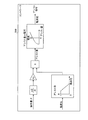
(実施の形態2)
図4は、本発明の実施の形態2であるロードセンシング方式の油圧駆動装置の油圧回路図を示したものである。ここで例示する油圧駆動装置は、実施の形態1と同様、建設機械において油圧シリンダ10の駆動を制御するもので、実施の形態1とは、伸長側パイロット油路に設ける絞りの構成が異なっている。以下、実施の形態1と異なる部分について詳細に説明し、実施の形態1と同様の構成については同一の符号を付してそれぞれの詳細説明を省略する。
(Embodiment 2)
FIG. 4 shows a hydraulic circuit diagram of a load sensing type hydraulic drive apparatus according to the second embodiment of the present invention. The hydraulic drive apparatus illustrated here controls the drive of the hydraulic cylinder 10 in the construction machine, as in the first embodiment, and differs from the first embodiment in the configuration of the throttle provided in the extension-side pilot oil passage. Yes. Hereinafter, parts different from those in the first embodiment will be described in detail, and the same components as those in the first embodiment will be denoted by the same reference numerals, and detailed descriptions thereof will be omitted.
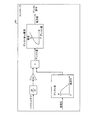
図4に示すように、実施の形態2の油圧駆動装置では、伸長側パイロット油路42の中間部に可変絞り144が設けてある。この可変絞り144は、油圧シリンダ10の負荷圧に応じて開口面積が変化するように動作するものである。具体的には、図5に示すように、負荷圧出力油路5から分岐した負荷圧出力分岐油路5aを可変絞り144の圧力室144aに接続し、油圧シリンダ10の負荷圧が大きいほど、可変絞り144の開口面積が大きくなるように構成してある。
As shown in FIG. 4, in the hydraulic drive device according to the second embodiment, a variable throttle 144 is provided in the middle portion of the extension pilot oil passage 42. The variable throttle 144 operates so that the opening area changes according to the load pressure of the hydraulic cylinder 10. Specifically, as shown in FIG. 5, the load pressure output branch oil passage 5a branched from the load pressure output oil passage 5 is connected to the pressure chamber 144a of the variable throttle 144, and as the load pressure of the hydraulic cylinder 10 increases, The opening area of the variable diaphragm 144 is configured to be large.
以下、上記のように構成した油圧駆動装置の作用について説明する。操作レバー41が図4に示すレバー中立位置にある場合には、方向制御弁30が図4に示す中立位置に維持されており、2つのアクチュエータポートa,bと、供給ポートc及びドレンポートdとの間が遮断された状態にある。この状態においては、油圧ポンプ20から吐出された油がアンロード弁7のバネ7aに対抗する圧力まで上昇し、アンロード弁7が開放するため油タンクTへと排出される。これにより、油圧ポンプ20の吐出圧力がアンロード弁7の設定圧力となり、この圧力が吐出圧力出力油路6を通じて吐出圧力室52bに加えられる。一方、負荷圧出力油路5を通じて負荷圧力室52aに加えられる圧力はゼロとなる。これらの結果、ポンプ容量制御弁52が第2位置となり、ポンプ容量制御シリンダ51のボトム室51dに油が供給され、油圧ポンプ20の容量が最小の状態に設定される。
Hereinafter, the operation of the hydraulic drive apparatus configured as described above will be described. When the operation lever 41 is in the lever neutral position shown in FIG. 4, the direction control valve 30 is maintained in the neutral position shown in FIG. 4, and the two actuator ports a and b, the supply port c, and the drain port d Is in a state of being interrupted. In this state, the oil discharged from the hydraulic pump 20 rises to a pressure that opposes the spring 7a of the unload valve 7, and is discharged to the oil tank T because the unload valve 7 is opened. Thereby, the discharge pressure of the hydraulic pump 20 becomes the set pressure of the unload valve 7, and this pressure is applied to the discharge pressure chamber 52 b through the discharge pressure output oil passage 6. On the other hand, the pressure applied to the load pressure chamber 52a through the load pressure output oil passage 5 becomes zero. As a result, the pump displacement control valve 52 is in the second position, oil is supplied to the bottom chamber 51d of the pump displacement control cylinder 51, and the displacement of the hydraulic pump 20 is set to the minimum state.
この状態から油圧シリンダ10を伸長動作させるべく操作レバー41を図4中の矢印A方向に操作すると、パイロット操作弁40から伸長側パイロット油路42を通じて方向制御弁30にパイロット圧が供給され、方向制御弁30が伸長位置に切り替わる。この結果、油圧シリンダ10のボトム室11に接続されたアクチュエータポートbと供給ポートcとの間が接続されるとともに、ヘッド室12に接続されたアクチュエータポートaとドレンポートdとの間が接続され、油圧ポンプ20から吐出された油によって油圧シリンダ10が伸長動作することになる。
When the operating lever 41 is operated in the direction of arrow A in FIG. 4 to extend the hydraulic cylinder 10 from this state, the pilot pressure is supplied from the pilot operating valve 40 to the direction control valve 30 through the extension-side pilot oil passage 42. The control valve 30 is switched to the extended position. As a result, the actuator port b and the supply port c connected to the bottom chamber 11 of the hydraulic cylinder 10 are connected, and the actuator port a and the drain port d connected to the head chamber 12 are connected. The hydraulic cylinder 10 is extended by the oil discharged from the hydraulic pump 20.
油圧シリンダ10に油が供給されると、負荷圧が負荷圧出力ポートeから負荷圧出力油路5に出力されることになり、アンロード弁7が閉じる。さらに、負荷圧力室52aに作用する負荷圧によってポンプ容量制御弁52が第2位置から第1位置となる方向に動作し、ポンプ容量制御シリンダ51のボトム室51dが減圧されて、油圧ポンプ20の容量が増大する。以降、負荷圧力室52aに導かれた油圧シリンダ10の負荷圧と、吐出圧力室52bに導かれた油圧ポンプ20の吐出圧力との差圧に応じてポンプ容量制御弁52が適宜動作し、油圧ポンプ20が油圧シリンダ10の負荷圧と油圧ポンプ20の吐出圧力との差圧に応じた容量に制御される。
When oil is supplied to the hydraulic cylinder 10, the load pressure is output from the load pressure output port e to the load pressure output oil passage 5, and the unload valve 7 is closed. Further, the pump capacity control valve 52 operates in the direction from the second position to the first position by the load pressure acting on the load pressure chamber 52a, the bottom chamber 51d of the pump capacity control cylinder 51 is depressurized, and the hydraulic pump 20 Capacity increases. Thereafter, the pump capacity control valve 52 operates appropriately according to the differential pressure between the load pressure of the hydraulic cylinder 10 guided to the load pressure chamber 52a and the discharge pressure of the hydraulic pump 20 guided to the discharge pressure chamber 52b. The pump 20 is controlled to have a capacity corresponding to the differential pressure between the load pressure of the hydraulic cylinder 10 and the discharge pressure of the hydraulic pump 20.
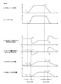
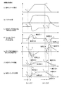
ここで、この実施の形態2の油圧駆動装置においても、伸長側パイロット油路42に可変絞り144を設け、かつこの可変絞り144の前後の圧力をそれぞれポンプ容量制御弁52に設けたアシスト圧力室52d,52eに作用させるようにしているため、操作レバー41を素早く操作した場合、可変絞り144の前後に生じる圧力差も大きなものとなり、図6のタイミングチャートに示すように、ポンプ容量制御弁52を迅速に動作させることができる。
Here, also in the hydraulic drive apparatus of the second embodiment, the assist pressure chamber in which the variable throttle 144 is provided in the extension pilot oil passage 42 and the pressure before and after the variable throttle 144 is provided in the pump displacement control valve 52, respectively. 52d and 52e, the pressure difference generated before and after the variable throttle 144 becomes large when the operation lever 41 is operated quickly, and the pump displacement control valve 52 is shown in the timing chart of FIG. Can be operated quickly.
すなわち、操作レバー41が矢印A方向(図4参照)へ操作され(図6(a)のt1)、パイロット操作弁40からパイロット圧の出力が開始されると(図6(b))、可変絞り144の前後に差圧が生じ(図6(d)のt2)、油圧シリンダ10の負荷圧が上昇して油圧ポンプ20の吐出圧力との差圧が小さくなる以前においても(図6(c)のt1〜t4)、油圧ポンプ20の吐出圧力と油圧シリンダ10の負荷圧との差圧による力+設定バネ52cの押圧力+可変絞り144の前後差圧による力<0となった時点(図6(e)のt3,t3′)からポンプ容量制御弁52が第1位置へ向けて動作し(図6(e))、油圧シリンダ10の負荷圧が作用する以前に油圧ポンプ20の容量を増大させることができるようになる(図6(f)のt3,t3′)。尚、図6(e)に示したポンプ容量制御弁52に働く力は、図4中の右向きに作用する力を正として記載してある。図6(d)のt2において発生した可変絞り144の前後差圧は、ポンプ容量制御弁52に対して左向きに作用するものであるため、図6(e)において上下を反転した形で記載してある。
That is, when the operation lever 41 is operated in the direction of arrow A (see FIG. 4) (t 1 in FIG. 6 (a)) and the pilot pressure output is started from the pilot operation valve 40 (FIG. 6 (b)), A differential pressure is generated before and after the variable throttle 144 (t 2 in FIG. 6D), and before the load pressure of the hydraulic cylinder 10 increases and the differential pressure with respect to the discharge pressure of the hydraulic pump 20 decreases (FIG. 6). (C 1 to t 4 ), the force due to the differential pressure between the discharge pressure of the hydraulic pump 20 and the load pressure of the hydraulic cylinder 10 + the pressing force of the setting spring 52 c + the force due to the differential pressure across the variable throttle 144 <0 The pump displacement control valve 52 operates from the time point (t 3 , t 3 ′ in FIG. 6E) toward the first position (FIG. 6E) and before the load pressure of the hydraulic cylinder 10 acts. Thus, the capacity of the hydraulic pump 20 can be increased (FIG. 6). t 3, t 3 of f) '). The force acting on the pump displacement control valve 52 shown in FIG. 6 (e) is described with the force acting rightward in FIG. 4 as positive. Differential pressure across the variable throttle 144 generated at t 2 in FIG. 6 (d) for the pump displacement control valve 52 is intended to act on the left, written in the form obtained by inverting the top and bottom in FIG. 6 (e) It is.
より具体的に説明すると、油圧シリンダ10を伸長動作させるべく図4中の矢印A方向に操作レバー41を操作すると、図6(b)に示すように、パイロット操作弁40から出力されるパイロット圧によって伸長側パイロット油路42の圧力が急激に上昇し、可変絞り144の上流側となるパイロット操作弁40と可変絞り144との間の圧力が、可変絞り144の下流側となる可変絞り144と方向制御弁30との間の圧力よりも高くなって差圧を生じる(図6(d)のt2)。この結果、ポンプ容量制御弁52が第2位置から第1位置に向けて迅速に動作し(図6(e)のt3,t3′)、ポンプ容量制御シリンダ51のボトム室51dが減圧されて油圧ポンプ20の容量が増大されることになる(図6(f)のt3,t3′)。これにより、操作レバー41を操作してから実際に油圧シリンダ10が伸長動作するまでのタイムラグを小さくし(図6(g)のt1〜t4→t1〜t3,t1〜t3′)、建設機械に良好な操作性を確保することができるため、例えば操作者に対して違和感を与える恐れがなくなる。
More specifically, when the operation lever 41 is operated in the direction of arrow A in FIG. 4 in order to extend the hydraulic cylinder 10, the pilot pressure output from the pilot operation valve 40 as shown in FIG. As a result, the pressure in the extension pilot oil passage 42 suddenly increases, and the pressure between the pilot operating valve 40 on the upstream side of the variable throttle 144 and the variable throttle 144 is changed to the variable throttle 144 on the downstream side of the variable throttle 144. The pressure becomes higher than the pressure between the directional control valve 30 and a differential pressure is generated (t 2 in FIG. 6D). As a result, the pump displacement control valve 52 operates quickly from the second position toward the first position (t 3 , t 3 ′ in FIG. 6E), and the bottom chamber 51d of the pump displacement control cylinder 51 is depressurized. Thus, the capacity of the hydraulic pump 20 is increased (t 3 and t 3 ′ in FIG. 6F ). Thus, t 1 of actually hydraulic cylinder 10 by operating the operation lever 41 to reduce the time lag until the operating extension (FIG. 6 (g) ~t 4 → t 1 ~t 3, t 1 ~t 3 ′ ) Since good operability can be ensured for the construction machine, for example, there is no possibility of giving an uncomfortable feeling to the operator.
しかも、上述の油圧駆動装置によれば、油圧シリンダ10の負荷圧が大きいほど、可変絞り144の開口面積が増大するため、図6(d)の二点鎖線で示すように、前後差圧が小さくなる。従って、油圧シリンダ10の負荷圧が大きい場合には、操作レバー41を素早く操作しても、図6(f)中の二点鎖線で示すように、油圧ポンプ20の容量増大率が小さくなり、図6(g)中の二点鎖線で示すように、油圧シリンダ10の伸長方向の移動も緩やかとなるため、急激に動作する事態を招来する恐れがない。
Moreover, according to the hydraulic drive device described above, as the load pressure of the hydraulic cylinder 10 increases, the opening area of the variable throttle 144 increases, so that the differential pressure across the front and rear is as shown by the two-dot chain line in FIG. Get smaller. Therefore, when the load pressure of the hydraulic cylinder 10 is large, even if the operation lever 41 is operated quickly, the capacity increase rate of the hydraulic pump 20 becomes small as shown by the two-dot chain line in FIG. As indicated by a two-dot chain line in FIG. 6G, the movement of the hydraulic cylinder 10 in the extending direction also becomes gentle, so there is no possibility of causing a sudden operation.
さらに、上述した作用効果は、油圧シリンダ10のボトム室11に供給する油の流量を増大させる場合ばかりでなく、ボトム室11に供給する油の流量を減少させ、油圧シリンダ10の動作速度を低減する場合にも同様に機能する。すなわち、図4中の矢印A方向への操作量を減少させると(図6(a)のt5)、パイロット操作弁40から伸長側パイロット油路42に出力されるパイロット圧が減少するため(図6(b))、可変絞り144の前後に差圧が生じ(図6(d)のt6)、油圧シリンダ10の負荷圧が下降して油圧ポンプ20の吐出圧力との差圧が大きくなる以前においても(図6(c)のt5〜t7)、油圧ポンプ20の吐出圧力と油圧シリンダ10の負荷圧との差圧による力+設定バネ52cの押圧力+可変絞り144の前後差圧による力>0となった時点でポンプ容量制御弁52が動作し(図6(e))、油圧シリンダ10の負荷圧が減少する以前に油圧ポンプ20の容量を減少させることができるようになる(図6(e)及び図6(f)のt6)。これにより、操作レバー41を操作してから実際に油圧シリンダ10の動作速度が低下を開始するまでのタイムラグを小さくし(図6(g)のt5〜t7→t5〜t6)、建設機械に良好な操作性を確保することができるため、例えば操作者に対して違和感を与える恐れがなくなる。この場合においても、油圧シリンダ10の負荷圧が大きいほど、可変絞り144の開口面積が増大するため、図6(d)の一点鎖線で示すように、前後差圧が小さくなる。従って、油圧シリンダ10の負荷圧が大きい場合には、操作レバー41を素早く操作しても、図6(f)中の一点鎖線で示すように、油圧ポンプ20の容量減少率が小さくなり、図6(g)中の一点鎖線で示すように、油圧シリンダ10の伸長動作も緩やかとなるため、急激に動作する事態を招来する恐れがない。
Further, the above-described operation and effect reduce not only the flow rate of oil supplied to the bottom chamber 11 of the hydraulic cylinder 10 but also the flow rate of oil supplied to the bottom chamber 11 to reduce the operating speed of the hydraulic cylinder 10. It works the same way. That is, if the amount of operation in the direction of arrow A in FIG. 4 is decreased (t 5 in FIG. 6A), the pilot pressure output from the pilot operation valve 40 to the extension pilot oil passage 42 decreases ( 6 (b)), a differential pressure is generated before and after the variable throttle 144 (t 6 in FIG. 6 (d)), the load pressure of the hydraulic cylinder 10 is lowered, and the differential pressure from the discharge pressure of the hydraulic pump 20 is large. Even before (t 5 to t 7 in FIG. 6C), the force due to the differential pressure between the discharge pressure of the hydraulic pump 20 and the load pressure of the hydraulic cylinder 10 + the pressing force of the setting spring 52 c + before and after the variable throttle 144 The pump displacement control valve 52 operates when the force due to the differential pressure> 0 (FIG. 6E), so that the displacement of the hydraulic pump 20 can be reduced before the load pressure of the hydraulic cylinder 10 is reduced. to become (t shown in FIG. 6 (e) and FIG. 6 (f) ). Accordingly, the operating speed of the actual hydraulic cylinder 10 by operating the operation lever 41 to reduce the time lag until the start of degradation (t 5 ~t 7 → t 5 ~t 6 in FIG. 6 (g)), Since good operability can be ensured for the construction machine, for example, there is no possibility of giving an uncomfortable feeling to the operator. Also in this case, as the load pressure of the hydraulic cylinder 10 increases, the opening area of the variable throttle 144 increases, so that the front-rear differential pressure decreases as indicated by the one-dot chain line in FIG. Therefore, when the load pressure of the hydraulic cylinder 10 is large, even if the operation lever 41 is operated quickly, the capacity reduction rate of the hydraulic pump 20 becomes small as shown by the one-dot chain line in FIG. As indicated by the alternate long and short dash line in 6 (g), the extension operation of the hydraulic cylinder 10 also becomes gentle, so there is no possibility of causing a sudden operation.
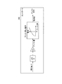
(実施の形態3)
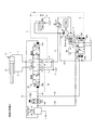
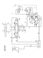
図7は、本発明の実施の形態3であるロードセンシング方式の油圧駆動装置の油圧回路図を示したものである。ここで例示する油圧駆動装置は、実施の形態1と同様、建設機械において油圧シリンダ10の駆動を制御するもので、実施の形態1とは、ポンプ容量制御弁の構成及びポンプ容量制御弁をアシストする構成が異なっている。以下、実施の形態1と異なる部分について詳細に説明し、実施の形態1と同様の構成については同一の符号を付してそれぞれの詳細説明を省略する。
(Embodiment 3)
FIG. 7 shows a hydraulic circuit diagram of a load sensing type hydraulic drive apparatus according to Embodiment 3 of the present invention. The hydraulic drive apparatus exemplified here controls the drive of the hydraulic cylinder 10 in the construction machine as in the first embodiment. The first embodiment assists the configuration of the pump displacement control valve and the pump displacement control valve. The configuration to do is different. Hereinafter, parts different from those in the first embodiment will be described in detail, and the same components as those in the first embodiment will be denoted by the same reference numerals, and detailed descriptions thereof will be omitted.
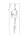
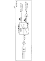
図7に示すように、実施の形態3の油圧駆動装置では、伸長側パイロット油路42の中間部に圧力センサ244が設けてある。圧力センサ244は、操作レバー41が操作された場合に伸長側パイロット油路42に出力されるパイロット圧を検出し、その検出結果をコントローラ60に出力するものである。
As shown in FIG. 7, in the hydraulic drive device of the third embodiment, a pressure sensor 244 is provided in the middle part of the extension-side pilot oil passage 42. The pressure sensor 244 detects the pilot pressure output to the extension-side pilot oil passage 42 when the operation lever 41 is operated, and outputs the detection result to the controller 60.
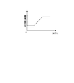
コントローラ60は、図8に示すように、圧力センサ244の検出したパイロット圧に基づいてその時間微分値を算出するとともに、算出した時間微分値に予め設定した比例定数k1を乗じた値をアシスト量として算出する。さらに、コントローラ60は、予め設定したアシスト量に対応する電流値を設定し、これをアシスト指令としてポンプ容量制御弁252のアシスト用電磁ソレノイド252fに出力する。図8に示すように、アシスト量に対応する電流値は、アシスト方向の正負に関わらず常に正の値、つまりポンプ容量制御弁252を常に図7において左向きに押す力となるように予め設定してある。
As shown in FIG. 8, the controller 60 calculates the time differential value based on the pilot pressure detected by the pressure sensor 244 and multiplies the calculated time differential value by a preset proportionality constant k1 as an assist amount. Calculate as Furthermore, the controller 60 sets a current value corresponding to a preset assist amount, and outputs this as an assist command to the assist electromagnetic solenoid 252f of the pump displacement control valve 252. As shown in FIG. 8, the current value corresponding to the assist amount is set in advance so as to always be a positive value regardless of the positive or negative assist direction, that is, the force that always pushes the pump displacement control valve 252 leftward in FIG. It is.
ポンプ容量制御弁252は、ポンプ容量制御シリンダ51とともに油圧ポンプ20のポンプ容量制御ユニット250を構成するものである。このポンプ容量制御弁252は、油圧ポンプ20の吐出圧と、方向制御弁30の負荷圧出力ポートeに出力される油圧シリンダ10の負荷圧との差圧に応じて切り替え動作し、ポンプ容量制御シリンダ51に対する油の供給制御を行う。具体的に説明すると、ポンプ容量制御弁252は、ポンプ容量制御シリンダ51のボトム室51dをタンク圧とする第1位置と、ポンプ容量制御シリンダ51のボトム室51dに油を供給する第2位置とを備えている。ポンプ容量制御弁252の一方の端部には、ポンプ容量制御弁252が第1位置となる方向に向けて押圧する負荷圧力室252aが設けてあり、他方の端部にはポンプ容量制御弁252が第2位置となる方向に向けて押圧する吐出圧力室252bが設けてある。負荷圧力室252aには、方向制御弁30の負荷圧出力ポートeとの間を接続する負荷圧出力油路5が接続してあり、吐出圧力室252bには、油圧ポンプ20の供給油路3から分岐した吐出圧力出力油路6が接続してある。
The pump capacity control valve 252 constitutes a pump capacity control unit 250 of the hydraulic pump 20 together with the pump capacity control cylinder 51. The pump capacity control valve 252 performs a switching operation according to a differential pressure between the discharge pressure of the hydraulic pump 20 and the load pressure of the hydraulic cylinder 10 output to the load pressure output port e of the direction control valve 30 to control the pump capacity. Oil supply control to the cylinder 51 is performed. More specifically, the pump displacement control valve 252 has a first position where the bottom chamber 51d of the pump displacement control cylinder 51 is at the tank pressure, and a second position where oil is supplied to the bottom chamber 51d of the pump displacement control cylinder 51. It has. At one end of the pump capacity control valve 252, a load pressure chamber 252a that presses the pump capacity control valve 252 toward the first position is provided, and at the other end, the pump capacity control valve 252 is provided. Is provided with a discharge pressure chamber 252b for pressing in the direction toward the second position. The load pressure chamber 252a is connected to a load pressure output oil passage 5 that is connected to the load pressure output port e of the direction control valve 30, and the discharge pressure chamber 252b is connected to the supply oil passage 3 of the hydraulic pump 20. A discharge pressure output oil passage 6 branched from is connected.
また、ポンプ容量制御弁252には、負荷圧力室252aに隣設してアシスト用電磁ソレノイド252fが設けてある。アシスト用電磁ソレノイド252fは、アシスト指令が与えられた場合に、これに含まれる電流値の大きさに応じてポンプ容量制御弁252を任意の方向に動作させるものである。
The pump displacement control valve 252 is provided with an assisting electromagnetic solenoid 252f adjacent to the load pressure chamber 252a. When an assist command is given, the assist electromagnetic solenoid 252f operates the pump displacement control valve 252 in an arbitrary direction according to the magnitude of the current value included therein.
以下、上記のように構成した油圧駆動装置の作用について説明する。操作レバー41が図7に示すレバー中立位置にある場合には、方向制御弁30が図7に示す中立位置に維持されており、2つのアクチュエータポートa,bと、供給ポートc及びドレンポートdとの間が遮断された状態にある。この状態においては、油圧ポンプ20から吐出された油がアンロード弁7のバネ7aに対抗する圧力まで上昇し、アンロード弁7が開放するため油タンクTへと排出される。これにより、油圧ポンプ20の吐出圧力がアンロード弁7の設定圧力となり、この圧力が吐出圧力出力油路6を通じて吐出圧力室252bに加えられる。一方、負荷圧出力油路5を通じて負荷圧力室252aに加えられる圧力はゼロとなる。これらの結果、ポンプ容量制御弁252が第2位置となり、ポンプ容量制御シリンダ51のボトム室51dに油が供給され、油圧ポンプ20の容量が最小の状態に設定される。
Hereinafter, the operation of the hydraulic drive apparatus configured as described above will be described. When the operation lever 41 is in the lever neutral position shown in FIG. 7, the direction control valve 30 is maintained in the neutral position shown in FIG. 7, and the two actuator ports a and b, the supply port c, and the drain port d Is in a state of being interrupted. In this state, the oil discharged from the hydraulic pump 20 rises to a pressure that opposes the spring 7a of the unload valve 7, and is discharged to the oil tank T because the unload valve 7 is opened. Thereby, the discharge pressure of the hydraulic pump 20 becomes the set pressure of the unload valve 7, and this pressure is applied to the discharge pressure chamber 252 b through the discharge pressure output oil passage 6. On the other hand, the pressure applied to the load pressure chamber 252a through the load pressure output oil passage 5 is zero. As a result, the pump displacement control valve 252 is in the second position, oil is supplied to the bottom chamber 51d of the pump displacement control cylinder 51, and the displacement of the hydraulic pump 20 is set to the minimum state.
この状態から油圧シリンダ10を伸長動作させるべく操作レバー41を図7中の矢印A方向に操作すると、パイロット操作弁40から伸長側パイロット油路42を通じて方向制御弁30にパイロット圧が供給され、方向制御弁30が伸長位置に切り替わる。この結果、油圧シリンダ10のボトム室11に接続されたアクチュエータポートbと供給ポートcとの間が接続されるとともに、ヘッド室12に接続されたアクチュエータポートaとドレンポートdとの間が接続され、油圧ポンプ20から吐出された油によって油圧シリンダ10が伸長動作することになる。
When the operation lever 41 is operated in the direction of arrow A in FIG. 7 to extend the hydraulic cylinder 10 from this state, pilot pressure is supplied from the pilot operation valve 40 to the direction control valve 30 through the extension-side pilot oil passage 42. The control valve 30 is switched to the extended position. As a result, the actuator port b and the supply port c connected to the bottom chamber 11 of the hydraulic cylinder 10 are connected, and the actuator port a and the drain port d connected to the head chamber 12 are connected. The hydraulic cylinder 10 is extended by the oil discharged from the hydraulic pump 20.
油圧シリンダ10に油が供給されると、負荷圧が負荷圧出力ポートeから負荷圧出力油路5に出力されることになり、アンロード弁7が閉じる。さらに、負荷圧力室252aに作用する負荷圧によってポンプ容量制御弁252が第2位置から第1位置となる方向に動作し、ポンプ容量制御シリンダ51のボトム室51dが減圧されて、油圧ポンプ20の容量が増大する。以降、負荷圧力室252aに導かれた油圧シリンダ10の負荷圧と、吐出圧力室252bに導かれた油圧ポンプ20の吐出圧力との差圧に応じてポンプ容量制御弁252が適宜動作し、油圧ポンプ20が油圧シリンダ10の負荷圧と油圧ポンプ20の吐出圧力との差圧に応じた容量に制御される。
When oil is supplied to the hydraulic cylinder 10, the load pressure is output from the load pressure output port e to the load pressure output oil passage 5, and the unload valve 7 is closed. Further, the pump capacity control valve 252 operates in the direction from the second position to the first position by the load pressure acting on the load pressure chamber 252a, the bottom chamber 51d of the pump capacity control cylinder 51 is depressurized, and the hydraulic pump 20 Capacity increases. Thereafter, the pump capacity control valve 252 operates appropriately in accordance with the differential pressure between the load pressure of the hydraulic cylinder 10 guided to the load pressure chamber 252a and the discharge pressure of the hydraulic pump 20 guided to the discharge pressure chamber 252b. The pump 20 is controlled to have a capacity corresponding to the differential pressure between the load pressure of the hydraulic cylinder 10 and the discharge pressure of the hydraulic pump 20.
ここで、この実施の形態3の油圧駆動装置においては、伸長側パイロット油路42に設けた圧力センサ244の検出結果からパイロット圧の時間微分値を算出し、時間微分値に応じた大きさのアシスト指令をコントローラ60からポンプ容量制御弁252のアシスト用電磁ソレノイド252fに出力するようにしているため、操作レバー41を素早く操作した場合、図9のタイミングチャートに示すように、コントローラ60によってポンプ容量制御弁252が動作されることになる。
Here, in the hydraulic drive device of the third embodiment, the time differential value of the pilot pressure is calculated from the detection result of the pressure sensor 244 provided in the extension-side pilot oil passage 42, and the magnitude according to the time differential value is calculated. Since the assist command is output from the controller 60 to the assisting electromagnetic solenoid 252f of the pump displacement control valve 252, when the operation lever 41 is operated quickly, the pump displacement is pumped by the controller 60 as shown in the timing chart of FIG. The control valve 252 is operated.
すなわち、操作レバー41が矢印A方向(図7参照)へ操作され(図9(a)のt1)、パイロット操作弁40から出力されるパイロット圧が上昇すると(図9(b))、パイロット圧の変化量に応じたアシスト指令がコントローラ60からポンプ容量制御弁252に出力され(図9(d)のt2〜t5)、油圧シリンダ10の負荷圧が上昇して油圧ポンプ20の吐出圧力との差圧が小さくなる以前においても(図9(c)のt1〜t4)、油圧ポンプ20の容量を増大させることができるようになる(図9(f)のt3)。
That is, when the operation lever 41 is operated in the direction of arrow A (see FIG. 7) (t 1 in FIG. 9A) and the pilot pressure output from the pilot operation valve 40 increases (FIG. 9B), the pilot An assist command corresponding to the amount of change in pressure is output from the controller 60 to the pump displacement control valve 252 (t 2 to t 5 in FIG. 9 (d)), and the load pressure of the hydraulic cylinder 10 rises to discharge the hydraulic pump 20. Even before the pressure difference from the pressure is reduced (t 1 to t 4 in FIG. 9C), the capacity of the hydraulic pump 20 can be increased (t 3 in FIG. 9F).
より具体的には、油圧シリンダ10を伸長動作させるべく図7中の矢印A方向に操作レバー41を操作すると、図9(b)に示すように、パイロット操作弁40から出力されるパイロット圧によって伸長側パイロット油路42の圧力が急激に上昇し、パイロット圧の変化量に応じたアシスト指令がコントローラ60からポンプ容量制御弁252に出力される(図9(d)のt2)。従って、ポンプ容量制御弁252が第2位置から第1位置に向けて迅速に動作し(図9(e)のt3)、ポンプ容量制御シリンダ51のボトム室51dが減圧されて油圧ポンプ20の容量が増大されることになる(図9(f)のt3)。これにより、操作レバー41を操作してから実際に油圧シリンダ10が伸長動作するまでのタイムラグを小さくし(図9(g)のt1〜t4→t1〜t3)、建設機械に良好な操作性を確保することができるため、例えば操作者に対して違和感を与える恐れがなくなる。尚、図9(e)に示したポンプ容量制御弁252に働く力は、図7中において右向きに作用する力を正として記載してある。図9(d)のt2において出力されたアシスト指令は、上述したように、ポンプ容量制御弁252を常に図7において左向きに押す力となるものであるため、図9(e)においては上下を反転した形で記載してある。
More specifically, when the operation lever 41 is operated in the direction of arrow A in FIG. 7 in order to extend the hydraulic cylinder 10, the pilot pressure output from the pilot operation valve 40 as shown in FIG. The pressure in the extension pilot oil passage 42 increases rapidly, and an assist command corresponding to the amount of change in the pilot pressure is output from the controller 60 to the pump displacement control valve 252 (t 2 in FIG. 9D). Accordingly, the pump displacement control valve 252 operates quickly from the second position to the first position (t 3 in FIG. 9 (e)), the bottom chamber 51d of the pump displacement control cylinder 51 is depressurized, and the hydraulic pump 20 The capacity will be increased (t 3 in FIG. 9 (f)). As a result, the time lag from when the operating lever 41 is operated until the hydraulic cylinder 10 is actually extended is reduced (t 1 to t 4 → t 1 to t 3 in FIG. 9G), which is good for construction machines. Therefore, for example, there is no possibility that the operator will feel uncomfortable. The force acting on the pump displacement control valve 252 shown in FIG. 9 (e) is described with the force acting rightward in FIG. 7 as positive. The assist command output at t 2 in FIG. 9 (d) as described above, because the always 7 the pump displacement control valve 252 and serves as a force pressing the left, up and down in FIG. 9 (e) Is shown in an inverted form.
さらに、上述した作用効果は、油圧シリンダ10のボトム室11に供給する油の流量を増大させる場合ばかりでなく、ボトム室11に供給する油の流量を減少させ、油圧シリンダ10の動作速度を低減する場合にも同様に機能する。すなわち、図7中の矢印A方向への操作量を減少させると(図9(a)のt6)、パイロット操作弁40から伸長側パイロット油路42に出力されるパイロット圧が減少するため(図9(b))、パイロット圧の変化量に応じたアシスト指令がコントローラ60からポンプ容量制御弁252に出力され(図9(d)のt7〜t9)、油圧シリンダ10の負荷圧が下降して油圧ポンプ20の吐出圧力との差圧が大きくなる以前においても(図9(c)のt6〜t8)、油圧ポンプ20の容量を減少させることができるようになる(図9(f)のt7)。これにより、操作レバー41を操作してから実際に油圧シリンダ10の動作速度が低下を開始するまでのタイムラグを小さくし(図9(g)のt6〜t8→t6〜t7)、建設機械に良好な操作性を確保することができるため、例えば操作者に対して違和感を与える恐れがなくなる。
Further, the above-described operation and effect reduce not only the flow rate of oil supplied to the bottom chamber 11 of the hydraulic cylinder 10 but also the flow rate of oil supplied to the bottom chamber 11 to reduce the operating speed of the hydraulic cylinder 10. It works the same way. That is, if the amount of operation in the direction of arrow A in FIG. 7 is decreased (t 6 in FIG. 9A), the pilot pressure output from the pilot operation valve 40 to the extension pilot oil passage 42 decreases ( FIG. 9 (b)), the assist command corresponding to the amount of change in the pilot pressure is outputted from the controller 60 to the pump displacement control valve 252 t 7 ~t 9 (FIG. 9 (d)), the load pressure of the hydraulic cylinder 10 Even before the pressure decreases and the differential pressure from the discharge pressure of the hydraulic pump 20 increases (t 6 to t 8 in FIG. 9C), the capacity of the hydraulic pump 20 can be reduced (FIG. 9). t 7 of the (f)). As a result, the time lag from when the operating lever 41 is operated until the operating speed of the hydraulic cylinder 10 actually starts to decrease is reduced (t 6 to t 8 → t 6 to t 7 in FIG. 9G). Since good operability can be ensured for the construction machine, for example, there is no possibility of giving an uncomfortable feeling to the operator.
(実施の形態4)
図10は、本発明の実施の形態4であるロードセンシング方式の油圧駆動装置の油圧回路図を示したものである。ここで例示する油圧駆動装置は、実施の形態3と同様、建設機械において油圧シリンダ10の駆動を制御するもので、実施の形態3とは、ポンプ容量制御弁をアシストする構成が異なっている。以下、実施の形態3と異なる部分について詳細に説明し、実施の形態3と同様の構成については同一の符号を付してそれぞれの詳細説明を省略する。
(Embodiment 4)
FIG. 10 shows a hydraulic circuit diagram of a load sensing type hydraulic drive apparatus according to the fourth embodiment of the present invention. The hydraulic drive apparatus illustrated here controls the drive of the hydraulic cylinder 10 in the construction machine, as in the third embodiment, and differs from the third embodiment in the configuration for assisting the pump displacement control valve. Hereinafter, parts different from the third embodiment will be described in detail, and the same components as those of the third embodiment will be denoted by the same reference numerals and detailed descriptions thereof will be omitted.
図10に示すように、実施の形態4の油圧駆動装置では、方向制御弁30の負荷圧出力ポートeに接続された負荷圧出力油路5に負荷圧力センサ245が設けてある。負荷圧力センサ245は、負荷圧出力油路5に出力される油圧シリンダ10の負荷圧を検出し、その検出結果をコントローラ260に出力するものである。
As shown in FIG. 10, in the hydraulic drive device according to the fourth embodiment, a load pressure sensor 245 is provided in the load pressure output oil passage 5 connected to the load pressure output port e of the directional control valve 30. The load pressure sensor 245 detects the load pressure of the hydraulic cylinder 10 output to the load pressure output oil passage 5 and outputs the detection result to the controller 260.
コントローラ260は、図11に示すように、圧力センサ244の検出したパイロット圧に基づいてその時間微分値を算出し、算出した時間微分値に予め設定した比例定数k2を乗じた値と、負荷圧力センサ245の検出した油圧シリンダ10の負荷圧に基づいて設定したアシスト率との積をアシスト量として算出する。さらに、コントローラ260は、予め設定したアシスト量に対応する電流値を設定し、これをアシスト指令としてポンプ容量制御弁252のアシスト用電磁ソレノイド252fに出力する。アシスト量に対応する電流値は、アシスト方向の正負に関わらず常に正の値、つまりポンプ容量制御弁252を常に図10において左向きに押す力となるように予め設定してある。また、コントローラ260が設定するアシスト率は、油圧シリンダ10の負荷圧がゼロの場合に1となり、以降、負荷圧が増大するほど減少する無次元数である。
As shown in FIG. 11, the controller 260 calculates the time differential value based on the pilot pressure detected by the pressure sensor 244, and multiplies the calculated time differential value by a preset proportionality constant k2 and the load pressure. The product of the assist rate set based on the load pressure of the hydraulic cylinder 10 detected by the sensor 245 is calculated as the assist amount. Furthermore, the controller 260 sets a current value corresponding to a preset assist amount, and outputs this as an assist command to the assist electromagnetic solenoid 252f of the pump displacement control valve 252. The current value corresponding to the assist amount is set in advance so as to always be a positive value regardless of whether the assist direction is positive or negative, that is, a force that always pushes the pump displacement control valve 252 leftward in FIG. The assist rate set by the controller 260 is 1 when the load pressure of the hydraulic cylinder 10 is zero, and is a dimensionless number that subsequently decreases as the load pressure increases.
以下、上記のように構成した油圧駆動装置の作用について説明する。操作レバー41が図10に示すレバー中立位置にある場合には、方向制御弁30が図10に示す中立位置に維持されており、2つのアクチュエータポートa,bと、供給ポートc及びドレンポートdとの間が遮断された状態にある。この状態においては、油圧ポンプ20から吐出された油がアンロード弁7のバネ7aに対抗する圧力まで上昇し、アンロード弁7が開放するため油タンクTへと排出される。これにより、油圧ポンプ20の吐出圧力がアンロード弁7の設定圧力となり、この圧力が吐出圧力出力油路6を通じて吐出圧力室252bに加えられる。一方、負荷圧出力油路5を通じて負荷圧力室252aに加えられる圧力はゼロとなる。これらの結果、ポンプ容量制御弁252が第2位置となり、ポンプ容量制御シリンダ51のボトム室51dに油が供給され、油圧ポンプ20の容量が最小の状態に設定される。
Hereinafter, the operation of the hydraulic drive apparatus configured as described above will be described. When the operation lever 41 is in the lever neutral position shown in FIG. 10, the direction control valve 30 is maintained in the neutral position shown in FIG. 10, and the two actuator ports a and b, the supply port c, and the drain port d Is in a state of being interrupted. In this state, the oil discharged from the hydraulic pump 20 rises to a pressure that opposes the spring 7a of the unload valve 7, and is discharged to the oil tank T because the unload valve 7 is opened. Thereby, the discharge pressure of the hydraulic pump 20 becomes the set pressure of the unload valve 7, and this pressure is applied to the discharge pressure chamber 252 b through the discharge pressure output oil passage 6. On the other hand, the pressure applied to the load pressure chamber 252a through the load pressure output oil passage 5 is zero. As a result, the pump displacement control valve 252 is in the second position, oil is supplied to the bottom chamber 51d of the pump displacement control cylinder 51, and the displacement of the hydraulic pump 20 is set to the minimum state.
この状態から油圧シリンダ10を伸長動作させるべく操作レバー41を図10中の矢印A方向に操作すると、パイロット操作弁40から伸長側パイロット油路42を通じて方向制御弁30にパイロット圧が供給され、方向制御弁30が伸長位置に切り替わる。この結果、油圧シリンダ10のボトム室11に接続されたアクチュエータポートbと供給ポートcとの間が接続されるとともに、ヘッド室12に接続されたアクチュエータポートaとドレンポートdとの間が接続され、油圧ポンプ20から吐出された油によって油圧シリンダ10が伸長動作することになる。
When the operating lever 41 is operated in the direction of arrow A in FIG. 10 to extend the hydraulic cylinder 10 from this state, the pilot pressure is supplied from the pilot operating valve 40 to the direction control valve 30 through the extension side pilot oil passage 42. The control valve 30 is switched to the extended position. As a result, the actuator port b and the supply port c connected to the bottom chamber 11 of the hydraulic cylinder 10 are connected, and the actuator port a and the drain port d connected to the head chamber 12 are connected. The hydraulic cylinder 10 is extended by the oil discharged from the hydraulic pump 20.
油圧シリンダ10に油が供給されると、負荷圧が負荷圧出力ポートeから負荷圧出力油路5に出力されることになり、アンロード弁7が閉じる。さらに、負荷圧力室252aに作用する負荷圧によってポンプ容量制御弁252が第2位置から第1位置となる方向に動作し、ポンプ容量制御シリンダ51のボトム室51dが減圧されて、油圧ポンプ20の容量が増大する。以降、負荷圧力室252aに導かれた油圧シリンダ10の負荷圧と、吐出圧力室252bに導かれた油圧ポンプ20の吐出圧力との差圧に応じてポンプ容量制御弁252が適宜動作し、油圧ポンプ20が油圧シリンダ10の負荷圧と油圧ポンプ20の吐出圧力との差圧に応じた容量に制御される。
When oil is supplied to the hydraulic cylinder 10, the load pressure is output from the load pressure output port e to the load pressure output oil passage 5, and the unload valve 7 is closed. Further, the pump capacity control valve 252 operates in the direction from the second position to the first position by the load pressure acting on the load pressure chamber 252a, the bottom chamber 51d of the pump capacity control cylinder 51 is depressurized, and the hydraulic pump 20 Capacity increases. Thereafter, the pump capacity control valve 252 operates appropriately in accordance with the differential pressure between the load pressure of the hydraulic cylinder 10 guided to the load pressure chamber 252a and the discharge pressure of the hydraulic pump 20 guided to the discharge pressure chamber 252b. The pump 20 is controlled to have a capacity corresponding to the differential pressure between the load pressure of the hydraulic cylinder 10 and the discharge pressure of the hydraulic pump 20.
ここで、この実施の形態4の油圧駆動装置においては、伸長側パイロット油路42に設けた圧力センサ244の検出結果からパイロット圧の時間微分値を算出し、時間微分値に応じた大きさのアシスト指令をコントローラ260からポンプ容量制御弁252のアシスト用電磁ソレノイド252fに出力するようにしているため、操作レバー41を素早く操作した場合、図12のタイミングチャートに示すように、コントローラ260によってポンプ容量制御弁252が動作されることになる。
Here, in the hydraulic drive device of the fourth embodiment, the time differential value of the pilot pressure is calculated from the detection result of the pressure sensor 244 provided in the extension-side pilot oil passage 42, and the magnitude according to the time differential value is calculated. Since the assist command is output from the controller 260 to the assist electromagnetic solenoid 252f of the pump displacement control valve 252, when the operation lever 41 is operated quickly, the controller 260 causes the pump displacement as shown in the timing chart of FIG. The control valve 252 is operated.
すなわち、操作レバー41が矢印A方向(図10参照)へ操作され(図12(a)のt1)、パイロット操作弁40から出力されるパイロット圧が上昇すると(図12(b))、パイロット圧の変化量に応じたアシスト指令がコントローラ260からポンプ容量制御弁252に出力され(図12(d)のt2〜t5)、油圧シリンダ10の負荷圧が上昇して油圧ポンプ20の吐出圧力との差圧が小さくなる以前においても(図12(c)のt1〜t4)、油圧ポンプ20の容量を増大させることができるようになる(図12(f)のt3,t3′)。
That is, when the operation lever 41 is operated in the direction of arrow A (see FIG. 10) (t 1 in FIG. 12A) and the pilot pressure output from the pilot operation valve 40 increases (FIG. 12B), the pilot An assist command corresponding to the amount of change in pressure is output from the controller 260 to the pump displacement control valve 252 (t 2 to t 5 in FIG. 12 (d)), and the load pressure of the hydraulic cylinder 10 rises to discharge the hydraulic pump 20. Even before the pressure difference from the pressure decreases (t 1 to t 4 in FIG. 12C), the capacity of the hydraulic pump 20 can be increased (t 3 and t in FIG. 12F). 3 ' ).
より具体的には、油圧シリンダ10を伸長動作させるべく図10中の矢印A方向に操作レバー41を操作すると、図12(b)に示すように、パイロット操作弁40から出力されるパイロット圧によって伸長側パイロット油路42の圧力が急激に上昇し、パイロット圧の変化量に応じたアシスト指令がコントローラ260からポンプ容量制御弁252に出力される(図12(d)のt2)。従って、ポンプ容量制御弁252が第2位置から第1位置に向けて迅速に動作し(図12(e)のt3,t3′)、ポンプ容量制御シリンダ51のボトム室51dが減圧されて油圧ポンプ20の容量が増大されることになる(図12(f)のt3,t3′)。これにより、操作レバー41を操作してから実際に油圧シリンダ10が伸長動作するまでのタイムラグを小さくし(図12(g)のt1〜t4→t1〜t3,t1〜t3′)、建設機械に良好な操作性を確保することができるため、例えば操作者に対して違和感を与える恐れがなくなる。
More specifically, when the operation lever 41 is operated in the direction of the arrow A in FIG. 10 to extend the hydraulic cylinder 10, the pilot pressure output from the pilot operation valve 40 as shown in FIG. The pressure in the extension pilot oil passage 42 increases rapidly, and an assist command corresponding to the amount of change in the pilot pressure is output from the controller 260 to the pump displacement control valve 252 (t 2 in FIG. 12D). Accordingly, the pump displacement control valve 252 operates quickly from the second position to the first position (t 3 , t 3 ′ in FIG. 12E), and the bottom chamber 51d of the pump displacement control cylinder 51 is depressurized. The capacity of the hydraulic pump 20 is increased (t 3 and t 3 ′ in FIG. 12F ). Thus, t 1 of actually hydraulic cylinder 10 by operating the operation lever 41 to reduce the time lag until the operating extension (Fig. 12 (g) ~t 4 → t 1 ~t 3, t 1 ~t 3 ′ ) Since good operability can be ensured for the construction machine, for example, there is no possibility of giving an uncomfortable feeling to the operator.
しかも、上述の油圧駆動装置によれば、油圧シリンダ10の負荷圧が大きいほど、アシスト率が減少するため、図12(d)に示すように、コントローラ260からアシスト用電磁ソレノイド252fに出力されるアシスト指令の電流値が小さくなる。従って、油圧シリンダ10の負荷圧が大きい場合には、操作レバー41を素早く操作しても、油圧ポンプ20の容量増大率が小さくなり(図12(f)中の二点鎖線)、油圧シリンダ10の伸長動作も緩やかとなるため(図12(g)中の二点鎖線)、急激に動作する事態を招来する恐れがない。
In addition, according to the hydraulic drive device described above, the assist rate decreases as the load pressure of the hydraulic cylinder 10 increases, so that the controller 260 outputs the assist electromagnetic solenoid 252f as shown in FIG. The assist command current value decreases. Therefore, when the load pressure of the hydraulic cylinder 10 is large, even if the operation lever 41 is operated quickly, the capacity increase rate of the hydraulic pump 20 becomes small (two-dot chain line in FIG. 12F), and the hydraulic cylinder 10 Since the extension operation is also gradual (two-dot chain line in FIG. 12G), there is no fear of causing a sudden operation.
さらに、上述した作用効果は、油圧シリンダ10のボトム室11に供給する油の流量を増大させる場合ばかりでなく、ボトム室11に供給する油の流量を減少させ、油圧シリンダ10の動作速度を低減する場合にも同様に機能する。すなわち、図10中の矢印A方向への操作量を減少させると(図12(a)のt6)、パイロット操作弁40から伸長側パイロット油路42に出力されるパイロット圧が減少するため(図12(b))、パイロット圧の変化量に応じたアシスト指令がコントローラ260からポンプ容量制御弁252に出力され(図12(d)のt7〜t9)、油圧シリンダ10の負荷圧が下降して油圧ポンプ20の吐出圧力との差圧が大きくなる以前においても(図12(c)のt6〜t8)、油圧ポンプ20の容量を減少させることができるようになる(図12(f)のt7)。これにより、操作レバー41を操作してから実際に油圧シリンダ10の動作速度が低下するまでのタイムラグを小さくし(図12(g)のt6〜t8→t6〜t7)、建設機械に良好な操作性を確保することができるため、例えば操作者に対して違和感を与える恐れがなくなる。この場合においても、油圧シリンダ10の負荷圧が大きいほど、図12(d)中の一点鎖線に示すように、コントローラ260からアシスト用電磁ソレノイド252fに出力されるアシスト指令の電流値が小さくなるため、油圧シリンダ10の負荷圧が大きい場合、操作レバー41を素早く操作しても、図12(f)中の一点鎖線に示すように、油圧ポンプ20の容量減少率が小さくなり、図12(g)中の一点鎖線に示すように、油圧シリンダ10の伸長動作も緩やかとなるため、急激に動作する事態を招来する恐れがない。
Further, the above-described operation and effect reduce not only the flow rate of oil supplied to the bottom chamber 11 of the hydraulic cylinder 10 but also the flow rate of oil supplied to the bottom chamber 11 to reduce the operating speed of the hydraulic cylinder 10. It works the same way. That is, if the operation amount in the direction of arrow A in FIG. 10 is decreased (t 6 in FIG. 12A), the pilot pressure output from the pilot operation valve 40 to the extension pilot oil passage 42 decreases ( In FIG. 12B, an assist command corresponding to the amount of change in pilot pressure is output from the controller 260 to the pump displacement control valve 252 (t 7 to t 9 in FIG. 12D), and the load pressure of the hydraulic cylinder 10 is changed. Even before the pressure decreases and the pressure difference from the discharge pressure of the hydraulic pump 20 increases (t 6 to t 8 in FIG. 12C), the capacity of the hydraulic pump 20 can be reduced (FIG. 12). t 7 of the (f)). As a result, the time lag from when the operating lever 41 is operated to when the operating speed of the hydraulic cylinder 10 actually decreases is reduced (t 6 to t 8 → t 6 to t 7 in FIG. 12G), and the construction machine Therefore, it is possible to ensure good operability, and for example, there is no possibility of giving the operator a sense of incongruity. Even in this case, as the load pressure of the hydraulic cylinder 10 increases, the current value of the assist command output from the controller 260 to the assisting electromagnetic solenoid 252f decreases as shown by the one-dot chain line in FIG. When the load pressure of the hydraulic cylinder 10 is large, even if the operation lever 41 is quickly operated, the capacity reduction rate of the hydraulic pump 20 becomes small as shown by the one-dot chain line in FIG. ), The extension operation of the hydraulic cylinder 10 is also slow, so there is no risk of a sudden operation.
(実施の形態5)
図13は、本発明の実施の形態5であるロードセンシング方式の油圧駆動装置の油圧回路図を示したものである。ここで例示する油圧駆動装置は、実施の形態3と同様、建設機械において油圧シリンダ10の駆動を制御するもので、実施の形態3とは、ポンプ容量制御弁及びコントローラの構成が異なっている。以下、実施の形態3と異なる部分について詳細に説明し、実施の形態3と同様の構成については同一の符号を付してそれぞれの詳細説明を省略する。
(Embodiment 5)
FIG. 13 shows a hydraulic circuit diagram of a load sensing type hydraulic drive apparatus according to the fifth embodiment of the present invention. The hydraulic drive device illustrated here controls the drive of the hydraulic cylinder 10 in the construction machine, as in the third embodiment, and differs from the third embodiment in the configuration of the pump displacement control valve and the controller. Hereinafter, parts different from the third embodiment will be described in detail, and the same components as those of the third embodiment will be denoted by the same reference numerals and detailed descriptions thereof will be omitted.
図13に示すように、実施の形態5の油圧駆動装置では、伸長側パイロット油路42の中間部に圧力センサ244が設けてある。圧力センサ244は、操作レバー41が操作された場合に伸長側パイロット油路42に出力されるパイロット圧を検出し、その検出結果をコントローラ360に出力するものである。
As shown in FIG. 13, in the hydraulic drive device of the fifth embodiment, a pressure sensor 244 is provided in the middle part of the extension-side pilot oil passage 42. The pressure sensor 244 detects the pilot pressure output to the extension-side pilot oil passage 42 when the operation lever 41 is operated, and outputs the detection result to the controller 360.
ポンプ容量制御弁352は、ポンプ容量制御シリンダ51とともに油圧ポンプ20のポンプ容量制御ユニット350を構成するものである。このポンプ容量制御弁352は、油圧ポンプ20の吐出圧と、方向制御弁30の負荷圧出力ポートeに出力される油圧シリンダ10の負荷圧との差圧に応じて切り替え動作し、ポンプ容量制御シリンダ51に対する油の供給制御を行うものである。具体的に説明すると、ポンプ容量制御弁352は、ポンプ容量制御シリンダ51のボトム室51dをタンク圧とする第1位置と、ポンプ容量制御シリンダ51のボトム室51dに油を供給する第2位置とを備えている。ポンプ容量制御弁352の一方の端部には、ポンプ容量制御弁352が第1位置となる方向に向けて押圧する負荷圧力室352aが設けてあり、他方の端部にはポンプ容量制御弁352が第2位置となる方向に向けて押圧する吐出圧力室352bが設けてある。負荷圧力室352aには、方向制御弁30の負荷圧出力ポートeとの間を接続する負荷圧出力油路5が接続してあり、吐出圧力室352bには、油圧ポンプ20の供給油路3から分岐した吐出圧力出力油路6が接続してある。
The pump capacity control valve 352 constitutes the pump capacity control unit 350 of the hydraulic pump 20 together with the pump capacity control cylinder 51. This pump capacity control valve 352 performs a switching operation according to the differential pressure between the discharge pressure of the hydraulic pump 20 and the load pressure of the hydraulic cylinder 10 output to the load pressure output port e of the direction control valve 30 to control the pump capacity. The oil supply control to the cylinder 51 is performed. More specifically, the pump displacement control valve 352 has a first position where the bottom chamber 51d of the pump displacement control cylinder 51 is at the tank pressure, and a second position where oil is supplied to the bottom chamber 51d of the pump displacement control cylinder 51. It has. At one end of the pump capacity control valve 352, there is provided a load pressure chamber 352a that presses the pump capacity control valve 352 toward the first position, and at the other end, the pump capacity control valve 352 is provided. Is provided with a discharge pressure chamber 352b that presses in the direction toward the second position. The load pressure chamber 352a is connected to a load pressure output oil passage 5 that connects to the load pressure output port e of the directional control valve 30, and the discharge pressure chamber 352b is connected to the supply oil passage 3 of the hydraulic pump 20. A discharge pressure output oil passage 6 branched from is connected.
また、ポンプ容量制御弁352には、負荷圧力室352a及び吐出圧力室352bのそれぞれに隣設してアシスト用電磁ソレノイド352f,352gが設けてある。アシスト用電磁ソレノイド352f,352gは、アシスト指令が与えられた場合に、それに含まれる電流値の大きさに応じてポンプ容量制御弁352を互いに反対方向に向けて押圧動作させるものである。以下、2つのアシスト用電磁ソレノイドを区別するため、負荷圧力室352aに隣設したものを「第1ソレノイド352f」と称し、吐出圧力室352bに隣設したものを「第2ソレノイド352g」と称する。
The pump capacity control valve 352 is provided with assisting electromagnetic solenoids 352f and 352g adjacent to the load pressure chamber 352a and the discharge pressure chamber 352b, respectively. When an assist command is given, the assist electromagnetic solenoids 352f and 352g press the pump displacement control valve 352 in directions opposite to each other according to the magnitude of the current value included therein. Hereinafter, in order to distinguish the two assisting electromagnetic solenoids, the one adjacent to the load pressure chamber 352a is referred to as "first solenoid 352f", and the one adjacent to the discharge pressure chamber 352b is referred to as "second solenoid 352g". .
コントローラ360は、図14に示すように、圧力センサ244の検出したパイロット圧に基づいてその時間微分値を算出するとともに、算出した時間微分値に予め設定した比例定数k3を乗じた値をアシスト量として算出する。さらに、コントローラ360は、予め設定したアシスト量に対応する電流値を設定する。アシスト量に対応する電流値は、アシスト方向の正負に応じて正負の値となるように予め設定してある。設定した電流値がゼロ以上である場合、コントローラ360は、これを第1ソレノイド352fに対するアシスト指令として出力する。これに対して設定した電流値がゼロ未満である場合、コントローラ360は、電流値を正の値に変換した後、これを第2ソレノイド352gに対するアシスト指令として出力する。
As shown in FIG. 14, the controller 360 calculates the time differential value based on the pilot pressure detected by the pressure sensor 244, and multiplies the calculated time differential value by a preset proportionality constant k <b> 3 as an assist amount. Calculate as Furthermore, the controller 360 sets a current value corresponding to a preset assist amount. The current value corresponding to the assist amount is set in advance so as to be a positive / negative value according to the positive / negative of the assist direction. When the set current value is zero or more, the controller 360 outputs this as an assist command for the first solenoid 352f. On the other hand, when the set current value is less than zero, the controller 360 converts the current value to a positive value, and then outputs this as an assist command for the second solenoid 352g.
以下、上記のように構成した油圧駆動装置の作用について説明する。操作レバー41が図13に示すレバー中立位置にある場合には、方向制御弁30が図13に示す中立位置に維持されており、2つのアクチュエータポートa,bと、供給ポートc及びドレンポートdとの間が遮断された状態にある。この状態においては、油圧ポンプ20から吐出された油がアンロード弁7のバネ7aに対抗する圧力まで上昇し、アンロード弁7が開放するため油タンクTへと排出される。これにより、油圧ポンプ20の吐出圧力がアンロード弁7の設定圧力となり、この圧力が吐出圧力出力油路6を通じて吐出圧力室352bに加えられる。一方、負荷圧出力油路5を通じて負荷圧力室352aに加えられる圧力はゼロとなる。これらの結果、ポンプ容量制御弁352が第2位置となり、ポンプ容量制御シリンダ51のボトム室51dに油が供給され、油圧ポンプ20の容量が最小の状態に設定される。
Hereinafter, the operation of the hydraulic drive apparatus configured as described above will be described. When the operation lever 41 is in the lever neutral position shown in FIG. 13, the direction control valve 30 is maintained in the neutral position shown in FIG. 13, and the two actuator ports a and b, the supply port c, and the drain port d Is in a state of being interrupted. In this state, the oil discharged from the hydraulic pump 20 rises to a pressure that opposes the spring 7a of the unload valve 7, and is discharged to the oil tank T because the unload valve 7 is opened. Thereby, the discharge pressure of the hydraulic pump 20 becomes the set pressure of the unload valve 7, and this pressure is applied to the discharge pressure chamber 352 b through the discharge pressure output oil passage 6. On the other hand, the pressure applied to the load pressure chamber 352a through the load pressure output oil passage 5 becomes zero. As a result, the pump displacement control valve 352 is in the second position, oil is supplied to the bottom chamber 51d of the pump displacement control cylinder 51, and the displacement of the hydraulic pump 20 is set to the minimum state.
この状態から油圧シリンダ10を伸長動作させるべく操作レバー41を図13中の矢印A方向に操作すると、パイロット操作弁40から伸長側パイロット油路42を通じて方向制御弁30にパイロット圧が供給され、方向制御弁30が伸長位置に切り替わる。この結果、油圧シリンダ10のボトム室11に接続されたアクチュエータポートbと供給ポートcとの間が接続されるとともに、ヘッド室12に接続されたアクチュエータポートaとドレンポートdとの間が接続され、油圧ポンプ20から吐出された油によって油圧シリンダ10が伸長動作することになる。
When the operation lever 41 is operated in the direction of arrow A in FIG. 13 to extend the hydraulic cylinder 10 from this state, the pilot pressure is supplied from the pilot operation valve 40 to the direction control valve 30 through the extension side pilot oil passage 42. The control valve 30 is switched to the extended position. As a result, the actuator port b and the supply port c connected to the bottom chamber 11 of the hydraulic cylinder 10 are connected, and the actuator port a and the drain port d connected to the head chamber 12 are connected. The hydraulic cylinder 10 is extended by the oil discharged from the hydraulic pump 20.
油圧シリンダ10に油が供給されると、負荷圧が負荷圧出力ポートeから負荷圧出力油路5に出力されることになり、アンロード弁7が閉じる。さらに、負荷圧力室352aに作用する負荷圧によってポンプ容量制御弁352が第2位置から第1位置となる方向に動作し、ポンプ容量制御シリンダ51のボトム室51dが減圧されて、油圧ポンプ20の容量が増大する。以降、負荷圧力室352aに導かれた油圧シリンダ10の負荷圧と、吐出圧力室352bに導かれた油圧ポンプ20の吐出圧力との差圧に応じてポンプ容量制御弁352が適宜動作し、油圧ポンプ20が油圧シリンダ10の負荷圧と油圧ポンプ20の吐出圧力との差圧に応じた容量に制御される。
When oil is supplied to the hydraulic cylinder 10, the load pressure is output from the load pressure output port e to the load pressure output oil passage 5, and the unload valve 7 is closed. Further, the pump capacity control valve 352 operates in the direction from the second position to the first position by the load pressure acting on the load pressure chamber 352a, the bottom chamber 51d of the pump capacity control cylinder 51 is depressurized, and the hydraulic pump 20 Capacity increases. Thereafter, the pump capacity control valve 352 appropriately operates according to the differential pressure between the load pressure of the hydraulic cylinder 10 guided to the load pressure chamber 352a and the discharge pressure of the hydraulic pump 20 guided to the discharge pressure chamber 352b. The pump 20 is controlled to have a capacity corresponding to the differential pressure between the load pressure of the hydraulic cylinder 10 and the discharge pressure of the hydraulic pump 20.
ここで、この実施の形態5の油圧駆動装置においては、伸長側パイロット油路42に設けた圧力センサ244の検出結果からパイロット圧の時間微分値を算出し、時間微分値に応じた大きさのアシスト指令をコントローラ360からポンプ容量制御弁352の対応するアシスト用電磁ソレノイド352f,352gに出力するようにしているため、操作レバー41を操作した場合、図15のタイミングチャートに示すように、コントローラ360によってポンプ容量制御弁352が動作されることになる。
Here, in the hydraulic drive device of the fifth embodiment, the time differential value of the pilot pressure is calculated from the detection result of the pressure sensor 244 provided in the extension-side pilot oil passage 42, and the magnitude according to the time differential value is calculated. Since the assist command is output from the controller 360 to the corresponding assist electromagnetic solenoids 352f and 352g of the pump displacement control valve 352, when the operation lever 41 is operated, as shown in the timing chart of FIG. As a result, the pump displacement control valve 352 is operated.
すなわち、操作レバー41が矢印A方向(図13参照)へ操作され(図15(a)のt1)、パイロット操作弁40から出力されるパイロット圧が上昇すると(図15(b))、パイロット圧の変化量に応じたアシスト指令がコントローラ360からポンプ容量制御弁352に出力され(図15(d)のt2〜t5)、油圧シリンダ10の負荷圧が上昇して油圧ポンプ20の吐出圧力との差圧が小さくなる以前においても(図15(c)のt1〜t4)、油圧ポンプ20の容量を増大させることができるようになる(図15(f)のt3)。
That is, when the operation lever 41 is operated in the direction of arrow A (see FIG. 13) (t 1 in FIG. 15A) and the pilot pressure output from the pilot operation valve 40 increases (FIG. 15B), the pilot An assist command corresponding to the amount of change in pressure is output from the controller 360 to the pump displacement control valve 352 (t 2 to t 5 in FIG. 15 (d)), and the load pressure of the hydraulic cylinder 10 rises to discharge the hydraulic pump 20. Even before the pressure difference from the pressure decreases (t 1 to t 4 in FIG. 15C), the capacity of the hydraulic pump 20 can be increased (t 3 in FIG. 15F).
より具体的には、油圧シリンダ10を伸長動作させるべく図13中の矢印A方向に操作レバー41を操作すると、図15(b)に示すように、パイロット操作弁40から出力されるパイロット圧が急激に上昇し、パイロット圧の変化量に応じたアシスト指令がコントローラ360からポンプ容量制御弁352に出力される(図15(d)のt2)。従って、ポンプ容量制御弁352が第2位置から第1位置に向けて迅速に動作し(図15(e)のt3)、ポンプ容量制御シリンダ51のボトム室51dが減圧されて油圧ポンプ20の容量が増大されることになる(図15(f)のt3)。これにより、操作レバー41を操作してから実際に油圧シリンダ10が伸長動作するまでのタイムラグを小さくし(図15(g)のt1〜t4→t1〜t3)、建設機械に良好な操作性を確保することができるため、例えば操作者に対して違和感を与える恐れがなくなる。
More specifically, when the operation lever 41 is operated in the direction of arrow A in FIG. 13 to extend the hydraulic cylinder 10, the pilot pressure output from the pilot operation valve 40 is changed as shown in FIG. The controller rapidly increases and an assist command corresponding to the amount of change in pilot pressure is output from the controller 360 to the pump displacement control valve 352 (t 2 in FIG. 15D). Accordingly, the pump displacement control valve 352 operates quickly from the second position toward the first position (t 3 in FIG. 15E), the bottom chamber 51d of the pump displacement control cylinder 51 is depressurized, and the hydraulic pump 20 The capacity will be increased (t 3 in FIG. 15 (f)). As a result, the time lag from when the operating lever 41 is operated until the hydraulic cylinder 10 is actually extended is reduced (t 1 to t 4 → t 1 to t 3 in FIG. 15G), which is good for construction machines. Therefore, for example, there is no possibility that the operator will feel uncomfortable.
さらに、上述した作用効果は、油圧シリンダ10のボトム室11に供給する油の流量を増大させる場合ばかりでなく、ボトム室11に供給する油の流量を減少させ、油圧シリンダ10の動作速度を低減する場合にも同様に機能する。すなわち、図13中の矢印A方向への操作量を減少させると(図15(a)のt6)、パイロット操作弁40から伸長側パイロット油路42に出力されるパイロット圧が減少するため(図15(b))、パイロット圧の変化量に応じたアシスト指令がコントローラ360からポンプ容量制御弁352に出力され(図15(d)のt7〜t9)、油圧シリンダ10の負荷圧が下降して油圧ポンプ20の吐出圧力との差圧が大きくなる以前においても(図15(c)のt6〜t8)、油圧ポンプ20の容量を減少させることができるようになる(図15(f)のt7)。これにより、操作レバー41を操作してから実際に油圧シリンダ10の動作速度が低下するまでのタイムラグを小さくし(図15(g)のt6〜t8→t6〜t7)、建設機械に良好な操作性を確保することができるため、例えば操作者に対して違和感を与える恐れがなくなる。
Further, the above-described operation and effect reduce not only the flow rate of oil supplied to the bottom chamber 11 of the hydraulic cylinder 10 but also the flow rate of oil supplied to the bottom chamber 11 to reduce the operating speed of the hydraulic cylinder 10. It works the same way. That is, if the operation amount in the direction of arrow A in FIG. 13 is reduced (t 6 in FIG. 15A), the pilot pressure output from the pilot operation valve 40 to the extension pilot oil passage 42 decreases ( In FIG. 15B, an assist command corresponding to the amount of change in pilot pressure is output from the controller 360 to the pump displacement control valve 352 (t 7 to t 9 in FIG. 15D), and the load pressure of the hydraulic cylinder 10 is changed. Even before the pressure decreases and the pressure difference from the discharge pressure of the hydraulic pump 20 increases (t 6 to t 8 in FIG. 15C), the capacity of the hydraulic pump 20 can be reduced (FIG. 15). t 7 of the (f)). As a result, the time lag from when the operation lever 41 is operated until the operating speed of the hydraulic cylinder 10 actually decreases is reduced (t 6 to t 8 → t 6 to t 7 in FIG. 15G), and the construction machine Therefore, it is possible to ensure good operability, and for example, there is no possibility of giving the operator a sense of incongruity.
(実施の形態6)
図16は、本発明の実施の形態6であるロードセンシング方式の油圧駆動装置の油圧回路図を示したものである。ここで例示する油圧駆動装置は、実施の形態3と同様、建設機械において油圧シリンダ10の駆動を制御するもので、実施の形態3とは、操作レバー、コントローラの構成及び方向制御弁が異なっている。以下、実施の形態3と異なる部分について詳細に説明し、実施の形態3と同様の構成については同一の符号を付してそれぞれの詳細説明を省略する。
(Embodiment 6)
FIG. 16 shows a hydraulic circuit diagram of a load sensing type hydraulic drive apparatus according to the sixth embodiment of the present invention. The hydraulic drive device illustrated here controls the drive of the hydraulic cylinder 10 in the construction machine, as in the third embodiment, and differs from the third embodiment in the operation lever, the configuration of the controller, and the direction control valve. Yes. Hereinafter, parts different from the third embodiment will be described in detail, and the same components as those of the third embodiment will be denoted by the same reference numerals and detailed descriptions thereof will be omitted.
操作レバー141は、ポテンショメータ140を介して操作電気信号を出力するものである。ポテンショメータ140は、操作レバー141がレバー中立位置から操作された場合、その操作量に応じた操作電気信号を、操作レバー141の操作方向に応じた方向制御弁130の電磁ソレノイド130a,130b及びコントローラ460に出力するものである。
The operation lever 141 outputs an operation electric signal via the potentiometer 140. When the operation lever 141 is operated from the lever neutral position, the potentiometer 140 outputs an operation electric signal corresponding to the operation amount to the electromagnetic solenoids 130a and 130b and the controller 460 of the direction control valve 130 corresponding to the operation direction of the operation lever 141. Is output.
コントローラ460は、操作レバー141の操作に伴うポテンショメータ140からの操作電気信号に基づいて方向制御弁130を動作するための指令信号を出力する。また、コントローラ460は、図17に示すように、ポテンショメータ140から出力された操作電気信号に基づいて操作レバー141の操作変化量を算出するとともに、算出した操作変化量に予め設定した比例定数k4を乗じた値をアシスト量として算出する。さらに、コントローラ460は、予め設定したアシスト量に対応する電流値を設定し、これをアシスト指令としてポンプ容量制御弁252のアシスト用電磁ソレノイド252fに出力する。同図に示すように、アシスト量に対応する電流値は、アシスト方向の正負に関わらず常に正の値、つまりポンプ容量制御弁252を常に図16において左向きに押す力となるように予め設定してある。
The controller 460 outputs a command signal for operating the direction control valve 130 based on an operation electric signal from the potentiometer 140 that is associated with the operation of the operation lever 141. Further, as shown in FIG. 17, the controller 460 calculates the operation change amount of the operation lever 141 based on the operation electric signal output from the potentiometer 140, and sets a proportional constant k4 set in advance to the calculated operation change amount. The multiplied value is calculated as the assist amount. Furthermore, the controller 460 sets a current value corresponding to a preset assist amount, and outputs this as an assist command to the assist electromagnetic solenoid 252f of the pump displacement control valve 252. As shown in the figure, the current value corresponding to the assist amount is set in advance so as to always be a positive value regardless of the positive or negative direction of the assist direction, that is, the force that always pushes the pump displacement control valve 252 leftward in FIG. It is.
方向制御弁130は、コントローラ460から出力される指令信号により動作し、2つのアクチュエータポートa,bに対する供給ポートcとドレンポートdとの接続態様を選択的に切り替えるものである。具体的には、操作レバー141が図16に示す中立位置にある場合、方向制御弁130は、2つのアクチュエータポートa,bと、供給ポートc及びドレンポートdとの間を遮断した状態に維持する。この状態から伸長位置に切り替わると、一方のアクチュエータポートbと供給ポートcとの間を接続するとともに、他方のアクチュエータポートaとドレンポートdとの間を接続する。中立位置から縮退位置に切り替わると、一方のアクチュエータポートbとドレンポートdとの間を接続するとともに、他方のアクチュエータポートaと供給ポートcとの間を接続した状態となる。
The direction control valve 130 operates according to a command signal output from the controller 460, and selectively switches the connection mode between the supply port c and the drain port d for the two actuator ports a and b. Specifically, when the operation lever 141 is in the neutral position shown in FIG. 16, the direction control valve 130 is maintained in a state where the two actuator ports a and b are disconnected from the supply port c and the drain port d. To do. When the state is switched to the extended position, one actuator port b and the supply port c are connected, and the other actuator port a and the drain port d are connected. When the neutral position is switched to the retracted position, one actuator port b and the drain port d are connected, and the other actuator port a and the supply port c are connected.
方向制御弁130の一方のアクチュエータポートbには、ボトム油路1を通じて油圧シリンダ10のボトム室11が接続してあり、他方のアクチュエータポートaには、ヘッド油路2を通じて油圧シリンダ10のヘッド室12が接続してある。方向制御弁130の供給ポートcには、油圧ポンプ20の吐出口との間を接続する供給油路3が接続してあり、方向制御弁130のドレンポートdには、油タンクTとの間を接続するドレン油路4が接続してある。
The bottom chamber 11 of the hydraulic cylinder 10 is connected to one actuator port b of the direction control valve 130 through the bottom oil passage 1, and the head chamber of the hydraulic cylinder 10 is connected to the other actuator port a through the head oil passage 2. 12 is connected. A supply oil passage 3 is connected to the supply port c of the directional control valve 130 and connected to the discharge port of the hydraulic pump 20. The drain port d of the directional control valve 130 is connected to the oil tank T. A drain oil passage 4 is connected.
また、方向制御弁130には、負荷圧出力ポートeが設けてある。負荷圧出力ポートeは、一方の供給ポートcを通じて油圧シリンダ10のヘッド室12に油が供給されている間、並びに他方の供給ポートcを通じて油圧シリンダ10のボトム室11に油が供給されている間、それぞれ油の供給圧を負荷圧として出力するものである。
Further, the direction control valve 130 is provided with a load pressure output port e. The load pressure output port e is supplied with oil to the head chamber 12 of the hydraulic cylinder 10 through one supply port c and to the bottom chamber 11 of the hydraulic cylinder 10 through the other supply port c. During this time, the oil supply pressure is output as the load pressure.
本実施の形態6では、操作レバー141をレバー中立位置から図16中の矢印A方向に操作した場合、コントローラ460を介して伸長側電磁ソレノイド130bに指令信号が出力され、方向制御弁130が中立位置から伸長位置に切り替わる。方向制御弁130が伸長位置に切り替わると、油圧シリンダ10のボトム室11に接続されたボトム油路1が、方向制御弁130のアクチュエータポートb及び供給ポートcを介して供給油路3に接続されるとともに、ヘッド室12に接続されたヘッド油路2が方向制御弁130のアクチュエータポートa及びドレンポートdを介してドレン油路4に接続される。
In the sixth embodiment, when the operation lever 141 is operated from the lever neutral position in the direction of arrow A in FIG. 16, a command signal is output to the extension electromagnetic solenoid 130b via the controller 460, and the direction control valve 130 is neutral. Switch from position to extended position. When the direction control valve 130 is switched to the extended position, the bottom oil passage 1 connected to the bottom chamber 11 of the hydraulic cylinder 10 is connected to the supply oil passage 3 via the actuator port b and the supply port c of the direction control valve 130. At the same time, the head oil passage 2 connected to the head chamber 12 is connected to the drain oil passage 4 via the actuator port a and the drain port d of the direction control valve 130.
これとは逆に、操作レバー141がレバー中立位置から図16中の矢印B方向に操作された場合には、コントローラ460から縮退側電磁ソレノイド130aに指令信号が出力され、方向制御弁130が中立位置から縮退位置に切り替わる。方向制御弁130が縮退位置に切り替わると、油圧シリンダ10のボトム室11に接続されたボトム油路1が方向制御弁130のアクチュエータポートb及びドレンポートdを介してドレン油路4に接続されるとともに、ヘッド室12に接続されたヘッド油路2が方向制御弁130のアクチュエータポートa及び供給ポートcを介して供給油路3に接続されることになる。
On the contrary, when the operation lever 141 is operated in the direction of arrow B in FIG. 16 from the lever neutral position, a command signal is output from the controller 460 to the degeneration-side electromagnetic solenoid 130a, and the direction control valve 130 is neutral. Switch from position to degenerate position. When the direction control valve 130 is switched to the retracted position, the bottom oil passage 1 connected to the bottom chamber 11 of the hydraulic cylinder 10 is connected to the drain oil passage 4 via the actuator port b and the drain port d of the direction control valve 130. At the same time, the head oil passage 2 connected to the head chamber 12 is connected to the supply oil passage 3 via the actuator port a and the supply port c of the direction control valve 130.
以下、上記のように構成した油圧駆動装置の作用について説明する。操作レバー141が図16に示すレバー中立位置にある場合には、方向制御弁130が図16に示す中立位置に維持されており、2つのアクチュエータポートa,bと、供給ポートc及びドレンポートdとの間が遮断された状態にある。この状態においては、油圧ポンプ20から吐出された油がアンロード弁7のバネ7aに対抗する圧力まで上昇し、アンロード弁7が開放するため油タンクTへと排出される。これにより、油圧ポンプ20の吐出圧力がアンロード弁7の設定圧力となり、この圧力が吐出圧力出力油路6を通じて吐出圧力室252bに加えられる。一方、負荷圧出力油路5を通じて負荷圧力室252aに加えられる圧力はゼロとなる。これらの結果、ポンプ容量制御弁252が第2位置となり、ポンプ容量制御シリンダ51のボトム室51dに油が供給され、油圧ポンプ20の容量が最小の状態に設定される。
Hereinafter, the operation of the hydraulic drive apparatus configured as described above will be described. When the operation lever 141 is in the lever neutral position shown in FIG. 16, the direction control valve 130 is maintained in the neutral position shown in FIG. 16, and the two actuator ports a and b, the supply port c, and the drain port d Is in a state of being interrupted. In this state, the oil discharged from the hydraulic pump 20 rises to a pressure that opposes the spring 7a of the unload valve 7, and is discharged to the oil tank T because the unload valve 7 is opened. Thereby, the discharge pressure of the hydraulic pump 20 becomes the set pressure of the unload valve 7, and this pressure is applied to the discharge pressure chamber 252 b through the discharge pressure output oil passage 6. On the other hand, the pressure applied to the load pressure chamber 252a through the load pressure output oil passage 5 is zero. As a result, the pump displacement control valve 252 is in the second position, oil is supplied to the bottom chamber 51d of the pump displacement control cylinder 51, and the displacement of the hydraulic pump 20 is set to the minimum state.
この状態から油圧シリンダ10を伸長動作させるべく操作レバー141を図16中の矢印A方向に操作すると、コントローラ460から方向制御弁130の伸長側電磁ソレノイド130bに指令信号が出力され、方向制御弁130が伸長位置に切り替わる。この結果、油圧シリンダ10のボトム室11に接続されたアクチュエータポートbと供給ポートcとの間が接続されるとともに、ヘッド室12に接続されたアクチュエータポートaとドレンポートdとの間が接続され、油圧ポンプ20から吐出された油によって油圧シリンダ10が伸長動作することになる。
When the operation lever 141 is operated in the direction of arrow A in FIG. 16 to extend the hydraulic cylinder 10 from this state, a command signal is output from the controller 460 to the extension-side electromagnetic solenoid 130b of the direction control valve 130, and the direction control valve 130 is output. Switches to the extended position. As a result, the actuator port b and the supply port c connected to the bottom chamber 11 of the hydraulic cylinder 10 are connected, and the actuator port a and the drain port d connected to the head chamber 12 are connected. The hydraulic cylinder 10 is extended by the oil discharged from the hydraulic pump 20.
油圧シリンダ10に油が供給されると、負荷圧が負荷圧出力ポートeから負荷圧出力油路5に出力されることになり、アンロード弁7が閉じる。さらに、負荷圧力室252aに作用する負荷圧によってポンプ容量制御弁252が第2位置から第1位置となる方向に動作し、ポンプ容量制御シリンダ51のボトム室51dが減圧されて、油圧ポンプ20の容量が増大する。以降、負荷圧力室252aに導かれた油圧シリンダ10の負荷圧と、吐出圧力室252bに導かれた油圧ポンプ20の吐出圧力との差圧に応じてポンプ容量制御弁252が適宜動作し、油圧ポンプ20が油圧シリンダ10の負荷圧と油圧ポンプ20の吐出圧力との差圧に応じた容量に制御される。
When oil is supplied to the hydraulic cylinder 10, the load pressure is output from the load pressure output port e to the load pressure output oil passage 5, and the unload valve 7 is closed. Further, the pump capacity control valve 252 operates in the direction from the second position to the first position by the load pressure acting on the load pressure chamber 252a, the bottom chamber 51d of the pump capacity control cylinder 51 is depressurized, and the hydraulic pump 20 Capacity increases. Thereafter, the pump capacity control valve 252 operates appropriately in accordance with the differential pressure between the load pressure of the hydraulic cylinder 10 guided to the load pressure chamber 252a and the discharge pressure of the hydraulic pump 20 guided to the discharge pressure chamber 252b. The pump 20 is controlled to have a capacity corresponding to the differential pressure between the load pressure of the hydraulic cylinder 10 and the discharge pressure of the hydraulic pump 20.
ここで、この実施の形態6の油圧駆動装置では、コントローラ460がポテンショメータ140から出力された操作電気信号に基づいて操作レバー141の操作変化量を算出するとともに、算出した操作変化量に応じた電流値を設定し、この電流値を含むアシスト指令をポンプ容量制御弁252のアシスト用電磁ソレノイド252fに出力するようにしている。従って、操作レバー141を素早く操作した場合、コントローラ460から大きな電流値を含むアシスト指令が出力されることになり、コントローラ460によってポンプ容量制御弁252が動作されることになる。これにより、ポンプ容量制御弁252が第2位置から第1位置に向けて迅速に動作し、ポンプ容量制御シリンダ51のボトム室51dが減圧されて油圧ポンプ20の容量が増大されることになり、操作レバー141を操作してから実際に油圧シリンダ10が伸長動作するまでのタイムラグを小さくし、建設機械に良好な操作性を確保することができるため、例えば操作者に対して違和感を与える恐れがなくなる。
Here, in the hydraulic drive device according to the sixth embodiment, the controller 460 calculates the operation change amount of the operation lever 141 based on the operation electric signal output from the potentiometer 140, and the current corresponding to the calculated operation change amount. A value is set, and an assist command including this current value is output to the assist electromagnetic solenoid 252f of the pump displacement control valve 252. Therefore, when the operation lever 141 is quickly operated, an assist command including a large current value is output from the controller 460, and the pump displacement control valve 252 is operated by the controller 460. Thereby, the pump capacity control valve 252 operates quickly from the second position toward the first position, the bottom chamber 51d of the pump capacity control cylinder 51 is decompressed, and the capacity of the hydraulic pump 20 is increased. Since the time lag from when the operation lever 141 is operated to when the hydraulic cylinder 10 is actually extended can be reduced and good operability can be ensured for the construction machine, for example, the operator may feel uncomfortable. Disappear.
上述した作用効果は、油圧シリンダ10のボトム室11に供給する油の流量を増大させる場合ばかりでなく、ボトム室11に供給する油の流量を減少させ、油圧シリンダ10の動作速度を低減する場合にも同様に機能する。すなわち、操作レバー141がレバー中立位置へ向けて矢印B方向(図16参照)に操作されると、ポテンショメータ140からコントローラ460に出力される電流値が減少し、アシスト量が負の値となる。従って、ポンプ容量制御弁252が第1位置から第2位置に向けて迅速に動作し、ポンプ容量制御シリンダ51のボトム室51dが昇圧して油圧ポンプ20の容量が減少されることになる。これにより、操作レバー141を操作してから実際に油圧シリンダ10の動作速度が低下するまでのタイムラグを小さくし、建設機械に良好な操作性を確保することができるため、例えば操作者に対して違和感を与える恐れがなくなる。
The above-described effect is not only when the flow rate of oil supplied to the bottom chamber 11 of the hydraulic cylinder 10 is increased, but also when the flow rate of oil supplied to the bottom chamber 11 is decreased and the operating speed of the hydraulic cylinder 10 is reduced. Works the same way. That is, when the operation lever 141 is operated in the arrow B direction (see FIG. 16) toward the lever neutral position, the current value output from the potentiometer 140 to the controller 460 decreases and the assist amount becomes a negative value. Accordingly, the pump displacement control valve 252 operates quickly from the first position toward the second position, and the bottom chamber 51d of the pump displacement control cylinder 51 is boosted to reduce the displacement of the hydraulic pump 20. As a result, the time lag from when the operating lever 141 is operated until the operating speed of the hydraulic cylinder 10 actually decreases can be reduced, and good operability can be ensured for the construction machine. There is no danger of feeling uncomfortable.
(実施の形態7)
図18は、本発明の実施の形態7であるロードセンシング方式の油圧駆動装置の油圧回路図を示したものである。ここで例示する油圧駆動装置は、実施の形態6と同様、建設機械において油圧シリンダ10の駆動を制御するもので、実施の形態6とは、ポンプ容量制御弁をアシストする構成が異なっている。以下、実施の形態6と異なる部分について詳細に説明し、実施の形態6と同様の構成については同一の符号を付してそれぞれの詳細説明を省略する。
(Embodiment 7)
FIG. 18 is a hydraulic circuit diagram of a load sensing type hydraulic drive apparatus according to the seventh embodiment of the present invention. The hydraulic drive apparatus illustrated here controls the drive of the hydraulic cylinder 10 in the construction machine, as in the sixth embodiment, and differs from the sixth embodiment in the configuration for assisting the pump displacement control valve. Hereinafter, parts different from the sixth embodiment will be described in detail, and the same components as those in the sixth embodiment will be denoted by the same reference numerals, and detailed descriptions thereof will be omitted.
図18に示すように、実施の形態7の油圧駆動装置では、方向制御弁130の負荷圧出力ポートeに接続された負荷圧出力油路5に負荷圧力センサ245が設けてある。負荷圧力センサ245は、負荷圧出力油路5に出力される油圧シリンダ10の負荷圧を検出し、その検出結果をコントローラ560に出力するものである。
As shown in FIG. 18, in the hydraulic drive device according to the seventh embodiment, a load pressure sensor 245 is provided in the load pressure output oil passage 5 connected to the load pressure output port e of the directional control valve 130. The load pressure sensor 245 detects the load pressure of the hydraulic cylinder 10 that is output to the load pressure output oil passage 5 and outputs the detection result to the controller 560.
コントローラ560は、図19に示すように、ポテンショメータ140から出力された操作電気信号に基づいて操作レバー141の操作変化量を算出し、算出した操作変化量に予め設定した比例定数k5を乗じた値と、負荷圧力センサ245の検出した油圧シリンダ10の負荷圧に基づいて設定したアシスト率との積をアシスト量として算出する。さらに、コントローラ560は、予め設定したアシスト量に対応する電流値を設定し、これをアシスト指令としてポンプ容量制御弁252のアシスト用電磁ソレノイド252fに出力する。同図に示すように、アシスト量に対応する電流値は、アシスト方向の正負に関わらず常に正の値となるように予め設定してある。また、コントローラ560が設定するアシスト率は、油圧シリンダ10の負荷圧がゼロの場合に1となり、以降、負荷圧が増大するほど減少する無次元数である。
As shown in FIG. 19, the controller 560 calculates the operation change amount of the operation lever 141 based on the operation electric signal output from the potentiometer 140, and multiplies the calculated operation change amount by a preset proportionality constant k5. And the assist rate set based on the load pressure of the hydraulic cylinder 10 detected by the load pressure sensor 245 is calculated as the assist amount. Furthermore, the controller 560 sets a current value corresponding to a preset assist amount, and outputs this as an assist command to the assist electromagnetic solenoid 252f of the pump displacement control valve 252. As shown in the figure, the current value corresponding to the assist amount is set in advance so as to always be a positive value regardless of whether the assist direction is positive or negative. The assist rate set by the controller 560 is a dimensionless number that is 1 when the load pressure of the hydraulic cylinder 10 is zero, and thereafter decreases as the load pressure increases.
以下、上記のように構成した油圧駆動装置の作用について説明する。操作レバー141が図18に示すレバー中立位置にある場合には、方向制御弁130が図18に示す中立位置に維持されており、2つのアクチュエータポートa,bと、供給ポートc及びドレンポートdとの間が遮断された状態にある。この状態においては、油圧ポンプ20から吐出された油がアンロード弁7のバネ7aに対抗する圧力まで上昇し、アンロード弁7が開放するため油タンクTへと排出される。これにより、油圧ポンプ20の吐出圧力がアンロード弁7の設定圧力となり、この圧力が吐出圧力出力油路6を通じて吐出圧力室252bに加えられる。一方、負荷圧出力油路5を通じて負荷圧力室252aに加えられる圧力はゼロとなる。これらの結果、ポンプ容量制御弁252が第2位置となり、ポンプ容量制御シリンダ51のボトム室51dに油が供給され、油圧ポンプ20の容量が最小の状態に設定される。
Hereinafter, the operation of the hydraulic drive apparatus configured as described above will be described. When the operation lever 141 is in the lever neutral position shown in FIG. 18, the direction control valve 130 is maintained in the neutral position shown in FIG. 18, and the two actuator ports a and b, the supply port c, and the drain port d Is in a state of being interrupted. In this state, the oil discharged from the hydraulic pump 20 rises to a pressure that opposes the spring 7a of the unload valve 7, and is discharged to the oil tank T because the unload valve 7 is opened. Thereby, the discharge pressure of the hydraulic pump 20 becomes the set pressure of the unload valve 7, and this pressure is applied to the discharge pressure chamber 252 b through the discharge pressure output oil passage 6. On the other hand, the pressure applied to the load pressure chamber 252a through the load pressure output oil passage 5 is zero. As a result, the pump displacement control valve 252 is in the second position, oil is supplied to the bottom chamber 51d of the pump displacement control cylinder 51, and the displacement of the hydraulic pump 20 is set to the minimum state.
この状態から油圧シリンダ10を伸長動作させるべく操作レバー141を図18中の矢印A方向に操作すると、コントローラ560から方向制御弁130の伸長側電磁ソレノイド130bに指令信号が出力され、方向制御弁130が伸長位置に切り替わる。この結果、油圧シリンダ10のボトム室11に接続されたアクチュエータポートbと供給ポートcとの間が接続されるとともに、ヘッド室12に接続されたアクチュエータポートaとドレンポートdとの間が接続され、油圧ポンプ20から吐出された油によって油圧シリンダ10が伸長動作することになる。
When the operation lever 141 is operated in the direction of arrow A in FIG. 18 to extend the hydraulic cylinder 10 from this state, a command signal is output from the controller 560 to the extension-side electromagnetic solenoid 130b of the direction control valve 130, and the direction control valve 130 is output. Switches to the extended position. As a result, the actuator port b and the supply port c connected to the bottom chamber 11 of the hydraulic cylinder 10 are connected, and the actuator port a and the drain port d connected to the head chamber 12 are connected. The hydraulic cylinder 10 is extended by the oil discharged from the hydraulic pump 20.
油圧シリンダ10に油が供給されると、負荷圧が負荷圧出力ポートeから負荷圧出力油路5に出力されることになり、アンロード弁7が閉じる。さらに、負荷圧力室252aに作用する負荷圧によってポンプ容量制御弁252が第2位置から第1位置となる方向に動作し、ポンプ容量制御シリンダ51のボトム室51dが減圧されて、油圧ポンプ20の容量が増大する。以降、負荷圧力室252aに導かれた油圧シリンダ10の負荷圧と、吐出圧力室252bに導かれた油圧ポンプ20の吐出圧力との差圧に応じてポンプ容量制御弁252が適宜動作し、油圧ポンプ20が油圧シリンダ10の負荷圧と油圧ポンプ20の吐出圧力との差圧に応じた容量に制御される。
When oil is supplied to the hydraulic cylinder 10, the load pressure is output from the load pressure output port e to the load pressure output oil passage 5, and the unload valve 7 is closed. Further, the pump capacity control valve 252 operates in the direction from the second position to the first position by the load pressure acting on the load pressure chamber 252a, the bottom chamber 51d of the pump capacity control cylinder 51 is depressurized, and the hydraulic pump 20 Capacity increases. Thereafter, the pump capacity control valve 252 operates appropriately in accordance with the differential pressure between the load pressure of the hydraulic cylinder 10 guided to the load pressure chamber 252a and the discharge pressure of the hydraulic pump 20 guided to the discharge pressure chamber 252b. The pump 20 is controlled to have a capacity corresponding to the differential pressure between the load pressure of the hydraulic cylinder 10 and the discharge pressure of the hydraulic pump 20.
ここで、この実施の形態7の油圧駆動装置では、コントローラ560がポテンショメータ140から出力された操作電気信号に基づいて操作レバー141の操作変化量を算出するとともに、算出した操作変化量に応じた電流値を設定し、この電流値を含むアシスト指令をポンプ容量制御弁252のアシスト用電磁ソレノイド252fに出力するようにしている。従って、操作レバー141を素早く操作した場合、コントローラ560から大きな電流値を含むアシスト指令が出力されることになり、コントローラ560によってポンプ容量制御弁252が動作されることになる。これにより、ポンプ容量制御弁252が第2位置から第1位置に向けて迅速に動作し、ポンプ容量制御シリンダ51のボトム室51dが減圧されて油圧ポンプ20の容量が増大されることになり、操作レバー141を操作してから実際に油圧シリンダ10が伸長動作するまでのタイムラグを小さくし、建設機械に良好な操作性を確保することができるため、例えば操作者に対して違和感を与える恐れがなくなる。
Here, in the hydraulic drive device according to the seventh embodiment, the controller 560 calculates the operation change amount of the operation lever 141 based on the operation electric signal output from the potentiometer 140, and the current corresponding to the calculated operation change amount. A value is set, and an assist command including this current value is output to the assist electromagnetic solenoid 252f of the pump displacement control valve 252. Therefore, when the operation lever 141 is quickly operated, an assist command including a large current value is output from the controller 560, and the pump displacement control valve 252 is operated by the controller 560. Thereby, the pump capacity control valve 252 operates quickly from the second position toward the first position, the bottom chamber 51d of the pump capacity control cylinder 51 is decompressed, and the capacity of the hydraulic pump 20 is increased. Since the time lag from when the operation lever 141 is operated to when the hydraulic cylinder 10 is actually extended can be reduced and good operability can be ensured for the construction machine, for example, the operator may feel uncomfortable. Disappear.
しかも、上述の油圧駆動装置によれば、油圧シリンダ10の負荷圧が大きいほど、アシスト率が減少するため、アシスト用電磁ソレノイド252fに出力されるアシスト指令の電流値が小さくなる。従って、油圧シリンダ10の負荷圧が大きい場合には、操作レバー141を素早く操作しても、油圧ポンプ20の容量増大率が小さくなり、油圧シリンダ10の伸長動作も緩やかとなるため、急激に動作する事態を招来する恐れがない。
In addition, according to the hydraulic drive device described above, the assist rate decreases as the load pressure of the hydraulic cylinder 10 increases, so the current value of the assist command output to the assisting electromagnetic solenoid 252f decreases. Therefore, when the load pressure of the hydraulic cylinder 10 is large, even if the operation lever 141 is operated quickly, the capacity increase rate of the hydraulic pump 20 becomes small, and the extension operation of the hydraulic cylinder 10 becomes slow. There is no fear of inviting a situation to do.
さらに、上述した作用効果は、油圧シリンダ10のボトム室11に供給する油の流量を増大させる場合ばかりでなく、ボトム室11に供給する油の流量を減少させ、油圧シリンダ10の動作速度を低減する場合にも同様に機能する。すなわち、操作レバー141がレバー中立位置へ向けて矢印B方向(図18参照)に操作されると、ポテンショメータ140からコントローラ560に出力される電流値が減少し、アシスト量が負の値となる。従って、ポンプ容量制御弁252が第1位置から第2位置に向けて迅速に動作し、ポンプ容量制御シリンダ51のボトム室51dが昇圧して油圧ポンプ20の容量が減少されることになる。これにより、操作レバー141を操作してから実際に油圧シリンダ10の動作速度が低下するまでのタイムラグを小さくし、建設機械に良好な操作性を確保することができるため、例えば操作者に対して違和感を与える恐れがなくなる。
Further, the above-described operation and effect reduce not only the flow rate of oil supplied to the bottom chamber 11 of the hydraulic cylinder 10 but also the flow rate of oil supplied to the bottom chamber 11 to reduce the operating speed of the hydraulic cylinder 10. It works the same way. That is, when the operation lever 141 is operated in the arrow B direction (see FIG. 18) toward the lever neutral position, the current value output from the potentiometer 140 to the controller 560 decreases, and the assist amount becomes a negative value. Accordingly, the pump displacement control valve 252 operates quickly from the first position toward the second position, and the bottom chamber 51d of the pump displacement control cylinder 51 is boosted to reduce the displacement of the hydraulic pump 20. As a result, the time lag from when the operating lever 141 is operated until the operating speed of the hydraulic cylinder 10 actually decreases can be reduced, and good operability can be ensured for the construction machine. There is no danger of feeling uncomfortable.
尚、上述した実施の形態1〜実施の形態7では、いずれも油圧シリンダ10を伸長する際の動作について例示しているが、本発明はこれらに限定されず、各実施の形態はいずれも油圧シリンダ10を縮退する際にも同様に動作し、同様の作用効果を奏することが可能である。
In each of the first to seventh embodiments described above, the operation when the hydraulic cylinder 10 is extended is illustrated, but the present invention is not limited to these, and each of the embodiments is hydraulic. When the cylinder 10 is retracted, the same operation can be performed and the same effect can be obtained.