JP2012138206A - Lever type connector and wire cover - Google Patents
Lever type connector and wire cover Download PDFInfo
- Publication number
- JP2012138206A JP2012138206A JP2010288415A JP2010288415A JP2012138206A JP 2012138206 A JP2012138206 A JP 2012138206A JP 2010288415 A JP2010288415 A JP 2010288415A JP 2010288415 A JP2010288415 A JP 2010288415A JP 2012138206 A JP2012138206 A JP 2012138206A
- Authority
- JP
- Japan
- Prior art keywords
- lever
- shaft
- housing
- receiving groove
- guide
- Prior art date
- Legal status (The legal status is an assumption and is not a legal conclusion. Google has not performed a legal analysis and makes no representation as to the accuracy of the status listed.)
- Granted
Links
Images


Classifications
-
- H—ELECTRICITY
- H01—ELECTRIC ELEMENTS
- H01R—ELECTRICALLY-CONDUCTIVE CONNECTIONS; STRUCTURAL ASSOCIATIONS OF A PLURALITY OF MUTUALLY-INSULATED ELECTRICAL CONNECTING ELEMENTS; COUPLING DEVICES; CURRENT COLLECTORS
- H01R13/00—Details of coupling devices of the kinds covered by groups H01R12/70 or H01R24/00 - H01R33/00
- H01R13/62—Means for facilitating engagement or disengagement of coupling parts or for holding them in engagement
- H01R13/629—Additional means for facilitating engagement or disengagement of coupling parts, e.g. aligning or guiding means, levers, gas pressure electrical locking indicators, manufacturing tolerances
- H01R13/62933—Comprising exclusively pivoting lever
-
- H—ELECTRICITY
- H01—ELECTRIC ELEMENTS
- H01R—ELECTRICALLY-CONDUCTIVE CONNECTIONS; STRUCTURAL ASSOCIATIONS OF A PLURALITY OF MUTUALLY-INSULATED ELECTRICAL CONNECTING ELEMENTS; COUPLING DEVICES; CURRENT COLLECTORS
- H01R13/00—Details of coupling devices of the kinds covered by groups H01R12/70 or H01R24/00 - H01R33/00
- H01R13/44—Means for preventing access to live contacts
- H01R13/447—Shutter or cover plate
-
- H—ELECTRICITY
- H01—ELECTRIC ELEMENTS
- H01R—ELECTRICALLY-CONDUCTIVE CONNECTIONS; STRUCTURAL ASSOCIATIONS OF A PLURALITY OF MUTUALLY-INSULATED ELECTRICAL CONNECTING ELEMENTS; COUPLING DEVICES; CURRENT COLLECTORS
- H01R13/00—Details of coupling devices of the kinds covered by groups H01R12/70 or H01R24/00 - H01R33/00
- H01R13/62—Means for facilitating engagement or disengagement of coupling parts or for holding them in engagement
- H01R13/629—Additional means for facilitating engagement or disengagement of coupling parts, e.g. aligning or guiding means, levers, gas pressure electrical locking indicators, manufacturing tolerances
- H01R13/62977—Pivoting levers actuating linearly camming means
-
- H—ELECTRICITY
- H01—ELECTRIC ELEMENTS
- H01R—ELECTRICALLY-CONDUCTIVE CONNECTIONS; STRUCTURAL ASSOCIATIONS OF A PLURALITY OF MUTUALLY-INSULATED ELECTRICAL CONNECTING ELEMENTS; COUPLING DEVICES; CURRENT COLLECTORS
- H01R13/00—Details of coupling devices of the kinds covered by groups H01R12/70 or H01R24/00 - H01R33/00
- H01R13/62—Means for facilitating engagement or disengagement of coupling parts or for holding them in engagement
- H01R13/629—Additional means for facilitating engagement or disengagement of coupling parts, e.g. aligning or guiding means, levers, gas pressure electrical locking indicators, manufacturing tolerances
- H01R13/62933—Comprising exclusively pivoting lever
- H01R13/62955—Pivoting lever comprising supplementary/additional locking means
Abstract
Description
本発明は、複数本の電線を覆うレバー式コネクタ、ワイヤカバーに関する。 The present invention relates to a lever-type connector and a wire cover that cover a plurality of electric wires.
近年、自動車等の分野で用いられる電気コネクタでは多極化が進んでいる。そして、多極に形成された電気コネクタでは、コネクタ同士の嵌合を行う際及び嵌合を解除する際に大きな力が必要となる。このため、自動車等の分野では、レバーによる倍力効果を利用して相手コネクタとの嵌合及び嵌合の解除を行うレバー式コネクタが使用されている(例えば特許文献1、2参照。)。 In recent years, electrical connectors used in the field of automobiles and the like have become multipolar. And in the electrical connector formed in multiple poles, big force is needed when fitting between connectors and releasing a fitting. For this reason, in the field of automobiles and the like, lever-type connectors that use the boosting effect of the lever to engage and release the mating connector are used (see, for example, Patent Documents 1 and 2).
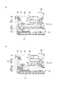
図6、図7に示すように、レバー式コネクタ1のレバー2は、一対の側板2a、2a及びこれら両側板を互いに連結する連結部2bを有し、U字形に形成されている。また、両側板2a、2aの先端部の内面には、それぞれレバー2をレバー式コネクタ1のハウジング3に取り付けるための回転軸4が設けられている。
As shown in FIGS. 6 and 7, the
しかしながら、レバー式コネクタ1の組立工程において、レバー2をハウジング3に取り付けるに際し、作業者は、手作業により、レバー2に形成された回転軸4、4を、軸受溝5に形成された軸受溝6に挿入させる必要がある。このとき、レバー2は、ハウジング3に対して所定の傾斜角度のときに回転軸4、4が軸受溝6に挿入できるようになっている。このため、作業者は、ハウジング3に対するレバー2の傾斜角度を、回転軸4、4が軸受溝6に合致するように傾斜させなければならず、これが煩わしい作業となっている。
さらに、図7(b)に示すように、レバー2の一部2cが、ハウジング3に取り付けられたワイヤカバー7に干渉し、レバー2の傾斜角度を、回転軸4、4が軸受溝6に合致する角度にできないこともある。さらに、そのままの状態からレバー2の回転軸4、4を無理やり軸受溝6に挿入しようとすると、レバー2が破損したり、軸受溝6が変形してしまう可能性もある。
本発明は、このような技術的課題に基づいてなされたもので、ワイヤカバーに対するレバーの装着を容易かつ確実に行うことのできるレバー式コネクタ、ワイヤカバーを提供することを目的とする。
However, when the
Further, as shown in FIG. 7 (b), a
The present invention has been made based on such a technical problem, and an object of the present invention is to provide a lever-type connector and a wire cover that can easily and reliably attach a lever to a wire cover.
かかる目的のもとになされた本発明は、コンタクトを収容するハウジングと、ハウジングの背面側に取り付けられ、ハウジングに収容されたコンタクトに接続された電線を覆うワイヤカバーと、一端側に軸部が設けられ、ハウジングに形成された軸収容溝に軸部が挿入されることで、当該軸部を中心としてハウジングに対して回転可能に設けられたレバーと、を備えたレバー式コネクタであって、レバーに、ハウジング側に突出する突起が形成され、ワイヤカバーに、軸収容溝に軸部を挿入するに際してレバーを定められた角度としたときに突起が突き当たるガイド部が形成され、ガイド部は、軸収容溝に対する軸部の挿入方向に沿って連続するガイド面と、ガイド面において軸収容溝とは反対側の端部に、ガイド面に直交または鋭角をなして形成され、軸部が軸収容溝から離間する方向に移動するのを阻止するストッパ面とを有することを特徴とする。
このような構成によれば、軸収容溝に軸部を挿入するときに、軸収容溝に対する軸部の挿入方向に沿って連続するガイド部に突起が突き当たることで、ハウジングに対するレバーの傾斜角度を位置決めすることができる。また、軸部が軸収容溝から離間する方向に移動するのを、ガイド面に対して直交または鋭角をなすストッパ面で阻止することにより、不用意にレバーが外れたり傾いたりするのを防止できる。
The present invention made for this purpose includes a housing that accommodates a contact, a wire cover that is attached to the back side of the housing and covers an electric wire connected to the contact accommodated in the housing, and a shaft portion on one end side. A lever-type connector provided with a lever provided rotatably with respect to the housing around the shaft portion by inserting the shaft portion into a shaft receiving groove formed in the housing, The lever is formed with a protrusion protruding toward the housing, and the wire cover is formed with a guide portion against which the protrusion abuts when the lever is set at a predetermined angle when inserting the shaft portion into the shaft receiving groove. A guide surface continuous along the insertion direction of the shaft portion with respect to the shaft receiving groove, and an end portion on the opposite side of the guide surface from the shaft receiving groove is orthogonal or acute to the guide surface. Is formed, the shaft portion and having a stopper surface for preventing the movement in a direction away from the shaft receiving groove.
According to such a configuration, when the shaft portion is inserted into the shaft receiving groove, the protrusion abuts against the guide portion that continues along the insertion direction of the shaft portion with respect to the shaft receiving groove, so that the inclination angle of the lever with respect to the housing is increased. Can be positioned. In addition, by preventing the shaft portion from moving in a direction away from the shaft receiving groove with a stopper surface that is orthogonal or acute with respect to the guide surface, it is possible to prevent the lever from being inadvertently detached or tilted. .
また、本発明は、上記したレバー式コネクタに用いられるワイヤカバーであって、接続対象に接続される複数本の電線を内部に収容するカバー本体と、カバー本体内から複数本の電線を外部に引き出す電線引出口と、電線引出口の周囲から突出して形成され、複数本の電線の引出方向を規制するとともに、複数本の電線が固定されるフード部と、ハウジングの軸収容溝に軸部を挿入するに際してレバーを定められた角度としたときに突起が突き当たるガイド部と、を備え、ガイド部は、軸収容溝に対する軸部の挿入方向に沿って連続するガイド面と、ガイド面において軸収容溝とは反対側の端部に、ガイド面に直交または鋭角をなして形成され、軸部が軸収容溝から離間する方向に移動するのを阻止するストッパ面とを有することを特徴とするワイヤカバーとすることもできる。 Further, the present invention is a wire cover used for the above-described lever-type connector, and includes a cover main body that accommodates a plurality of electric wires connected to a connection target, and a plurality of electric wires from the inside of the cover main body to the outside. An electric wire outlet to be drawn out, formed to protrude from the periphery of the electric wire outlet, regulates the drawing direction of the plurality of wires, and a shaft portion to the shaft receiving groove of the housing, and a hood portion to which the plurality of wires are fixed And a guide portion against which the protrusion abuts when the lever is at a predetermined angle for insertion, and the guide portion is a guide surface that is continuous along the insertion direction of the shaft portion with respect to the shaft receiving groove, and the shaft is accommodated in the guide surface. A stopper surface is formed at an end opposite to the groove so as to form an orthogonal or acute angle with the guide surface, and prevents the shaft portion from moving in a direction away from the shaft receiving groove. It may be a wire cover.
本発明によれば、軸収容溝に軸部を挿入するときに、軸収容溝に対する軸部の挿入方向に沿って連続するガイド部に突起が突き当たることで、ハウジングに対するレバーの傾斜角度を位置決めすることができる。また、軸部が軸収容溝から離間する方向に移動するのをストッパ面で阻止することにより、不用意にレバーが外れたり傾いたりするのを防止できる。このようにして、ワイヤカバーに対するレバーの装着を容易かつ確実に行うことが可能となる。 According to the present invention, when the shaft portion is inserted into the shaft receiving groove, the protrusion abuts against the guide portion continuous along the inserting direction of the shaft portion with respect to the shaft receiving groove, thereby positioning the inclination angle of the lever with respect to the housing. be able to. Further, by preventing the shaft portion from moving in the direction away from the shaft housing groove by the stopper surface, it is possible to prevent the lever from being inadvertently detached or tilted. In this way, the lever can be easily and reliably attached to the wire cover.
以下、添付図面に示す実施の形態に基づいてこの発明を詳細に説明する。
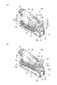
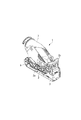
図1に示すように、レバー式コネクタ100は、複数のコンタクト(図示せず)を収容するハウジング10と、ハウジング10の一面側に取り付けられたワイヤカバー20と、ハウジング10に取り付けられたレバー30とを備えている。
Hereinafter, the present invention will be described in detail based on embodiments shown in the accompanying drawings.
As shown in FIG. 1, the lever-
図2に示すように、ハウジング10は、ワイヤカバー20に対向する対向面10aとその反対面10bを結ぶ方向に貫通するコンタクト収容孔11を複数有している。対向面10a、反対面10bは、一方向に長い長方形状をなしている。
As shown in FIG. 2, the
図1に示したように、ハウジング10には、対向面10aの両側に、それぞれ対向面10aの長手方向に沿って延びるスライダ収容スロット12が設けられている。そして、各スライダ収容スロット12には、板状のスライダ13がスライダ収容スロット12の連続する方向に移動可能に収容されている。
As shown in FIG. 1, the
各スライダ13は、平板状に形成され、相手コネクタに設けられたカムピン(図示せず)の引き込み及び押し出しを行うカム溝(図示せず)が複数設けられている。
また、図3に示すように、各スライダ13の一端部には、レバー30の後述するスライダ移動用軸35が回転自在に支持される軸受溝15が設けられている。この軸受溝15は、スライダ収容スロット12にスライダ13を収容した状態において、スライダ収容スロット12から外部に露出するよう設けられている。
Each
As shown in FIG. 3, a
また、図2に示したように、ハウジング10の対向面10aの一端部には、レバー30の後述する回転軸(軸部)34がそれぞれ回動自在に支持される軸受溝(軸収容溝)16が設けられている。
Further, as shown in FIG. 2, a bearing groove (shaft housing groove) in which a rotation shaft (shaft portion) 34 (to be described later) of the
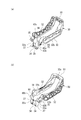
図4に示すように、レバー30は、互いに平行に延びる一対の側板32及びこれら両側板32の他端を互いに連結する連結部33を有し、U字形に形成されている。
As shown in FIG. 4, the
両側板32の一端には、両側板32の延びる方向に対して、一定の角度傾斜した方向に延びるステー部32a,32aが形成されている。
各ステー部32aの外面には、それぞれスライダ13の軸受溝15に嵌合するスライダ移動用軸35が外側に向かって突出するように形成され、内面には、それぞれハウジング10の軸受溝16に嵌合する回転軸34が内側に向かって突出するように設けられている。
また、両側板32の一端部の内面には、それぞれ内側に向かって延びる連結板37が設けられている。
At both ends of the
A
Further, a connecting
さらに、両側板32の一端側の内面には、平面部38が形成されている。
両側版32の一端側の内面には、回転軸34およびスライダ移動用軸35に対向した領域に、ガイド突起(突起)60が形成されている。このガイド突起60は、平面部38に対して内側に向けて突出して形成されている。
ガイド突起60は、平面部38側に、平面部38に直交する平面状の被ガイド面60aを有している。また、被ガイド面60aに隣接して、平面部38に直交し、かつ被ガイド面60aに対して鋭角をなすよう形成されたバックアップ面60bが形成されている。
Further, a
A guide protrusion (protrusion) 60 is formed on the inner surface on one end side of the both
The
連結部33には、ワイヤカバー20の後述するロック部材27のロック片27bが係止する凹部33aが設けられている。
The connecting
図5に示すように、ワイヤカバー20は、ハウジング10に収容されたコンタクトに接続されている複数本の電線(図示せず)を覆って内部に収容するカバー本体21と、カバー本体21の両側に設けられたストッパ部22とを有している。カバー本体21の厚さは、レバー30の両側板32の間隔よりも小さく形成されている。一方、ストッパ部22は、レバー30の両側板32の間隔よりも大きく形成されている。これにより、ストッパ部22は、レバー30を引き起こす方向への回転角度を規制する。
As shown in FIG. 5, the
ストッパ部22の一端部には、ハウジング10に収容されたコンタクトに接続されている電線を束ねた状態で外部に導出させる電線引出口24が設けられている。また、ストッパ部22の電線引出口24の周囲には、一方に向かって突出するフード部25が設けられている。
One end portion of the
カバー本体21の一端部には、スライダ移動用軸35、回転軸34を軸受溝15、16に嵌合させるときにレバー30の角度を規制するためのガイド部70が形成されている。このガイド部70は、軸受溝15、16に対するスライダ移動用軸35、回転軸34の挿入方向に沿って形成された直線状のガイド面70aと、ガイド面70aにおいて、スライダ移動用軸35、回転軸34から離間する側の端部に連続し、ガイド面70aに対して直交または鋭角な交差角度θに形成された顎面(ストッパ面)70bとを有する。
At one end portion of the cover
カバー本体21の他端には、レバー30を倒した状態にロック保持するロック部材27が設けられている。ロック部材27は、片持ち梁の板ばね状に形成され、板ばね27aと、板ばね27aに設けられたロック片27b及び解除用凸部27cとを有している。ロック片27bは、レバー30を倒したときに連結部33の凹部33aに係止するように設けられている。解除用凸部27cは、これを押圧することで板ばね27aが弾性変形してロック片27bと連結部33の凹部33aとの係止を解除する。
The other end of the
また、カバー本体21には、引き起こした状態のレバー30が倒れるのを阻止するロック用凸部28が設けられている。各ロック用凸部28は、レバー30の各側板32に形成された段差32bに係止するように設けられている。
Further, the
次に、レバー式コネクタ100の組み立て方法について説明する。
レバー式コネクタ100を組み立てる際には、まず、ハウジング10の複数のコンタクト収容孔11に、それぞれ電線に接続されたコンタクトを収容する。また、ハウジング10の両スライダ収容スロット12に、それぞれスライダ13を挿入する。
Next, a method for assembling the
When the lever-
次に、複数のコンタクトが収容されたハウジング10に、ワイヤカバー20を取り付ける。ハウジング10へのワイヤカバー20の取り付けが完了した状態では、ハウジング10に収容された複数のコンタクトに接続されている電線が、束ねられた状態でワイヤカバー20に収容され、電線引出口24から外部に導出される。
Next, the
次に、ワイヤカバー20が取り付けられたハウジング10に、レバー30を取り付ける。ワイヤカバー20が取り付けられたハウジング10にレバー30を取り付ける際には、レバー30を、両側板32がワイヤカバー20の背面側を跨ぎ、両側板32でワイヤカバー20を挟み込んだ状態となるようにワイヤカバー20に配置する必要がある。
Next, the
したがって、ハウジング10にレバー30を取り付ける際には、まず、手作業によりレバー30の両側板32の先端部を拡げ、両側板32の連結板37の先端の間に、ワイヤカバー20を挿入する。
レバー30をさらに押し込むと、両側板32の連結板37の先端が、それぞれワイヤカバー20のカバー本体21を乗り越える。そして、レバー30の連結部33の変形が解除され、レバー30が、両側板32でワイヤカバー20を挟み込んだ状態でワイヤカバー20に配置される。
Therefore, when attaching the
When the
そして、レバー30の両側板32の回転軸34を、それぞれハウジング10の各軸受溝16に嵌合するとともに、レバー30の両側板32のスライダ移動用軸35を、それぞれ各スライダ13の軸受溝15に嵌合する。
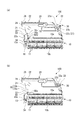
このとき、図2(a)に示すように、ワイヤカバー20にはガイド部70が形成されており、レバー30のガイド突起60を、このガイド部70に押し当てることで、レバー30の傾斜角度を位置決めする。より詳しくは、ガイド部70のガイド面70aと、ガイド突起60の被ガイド面60aとを突き合わせることにより、レバー30のワイヤカバー20に対する傾斜角度が位置決めされる。そして、その状態のまま、ガイド面70aに沿って、レバー30をスライドさせていくと、スライダ移動用軸35、回転軸34を、軸受溝15、16に嵌合させることができる。
The rotating
At this time, as shown in FIG. 2A, a
このようにして、レバー30がワイヤカバー20に取り付けられ、レバー式コネクタ100の組み立てが完了する。
In this way, the
このようにして、レバー30を、軸受溝15、16に容易かつ確実に嵌合させることが可能となる。その結果、レバー式コネクタ100の組立性が向上する。
またこのとき、ガイド部70には顎面70bが形成されているため、レバー30が、スライダ移動用軸35、回転軸34の軸受溝15、16への嵌合方向と逆方向に移動しようとすると、顎面70bにガイド部70が衝突する。さらに、顎面70bは、ガイド面70aに対して直角であるため、ガイド突起60がガイド部70から外れてしまいにくい。
In this way, the
At this time, since the
なお、上記実施形態では、ガイド部70を、ガイド面70aと顎面70bとからなる略L字状としたが、これに限るものではなく、顎面70bをガイド面70aに対して鋭角に形成しても良いし、顎面70bの先端部に、軸受溝15、16側に延びる延長部を設けることで、略J字状等としてもよい。これにより、レバー30の装着時にガイド部70からガイド突起60が外れるのをより確実に防止できる。
また、上記実施形態では、レバー式コネクタ100の構成を説明したが、ガイド突起60、ガイド部70を設けるのであれば、ハウジング10、ワイヤカバー20、レバー30の構成についてはいかなるものとしてもよい。
これ以外にも、本発明の主旨を逸脱しない限り、上記実施の形態で挙げた構成を取捨選択したり、他の構成に適宜変更することが可能である。
In the above embodiment, the
Moreover, although the structure of the lever-
In addition to this, as long as it does not depart from the gist of the present invention, the configuration described in the above embodiment can be selected or changed to another configuration as appropriate.
10…ハウジング、15…軸受溝、16…軸受溝(軸収容溝)、20…ワイヤカバー、21…カバー本体、22…ストッパ部、24…電線引出口、25…フード部、30…レバー、34…回転軸(軸部)、35…スライダ移動用軸、60…ガイド突起(突起)、60a…被ガイド面、60b…バックアップ面、70…ガイド部、70a…ガイド面、70b…顎面(ストッパ面)、100…レバー式コネクタ
DESCRIPTION OF
Claims (2)
前記ハウジングの背面側に取り付けられ、前記ハウジングに収容されたコンタクトに接続された電線を覆うワイヤカバーと、
一端側に軸部が設けられ、前記ハウジングに形成された軸収容溝に前記軸部が挿入されることで、当該軸部を中心として前記ハウジングに対して回転可能に設けられたレバーと、
を備えたレバー式コネクタであって、
前記レバーに、前記ハウジング側に突出する突起が形成され、
前記ワイヤカバーに、前記軸収容溝に前記軸部を挿入するに際して前記レバーを定められた角度としたときに前記突起が突き当たるガイド部が形成され、
前記ガイド部は、前記軸収容溝に対する前記軸部の挿入方向に沿って連続するガイド面と、前記ガイド面において前記軸収容溝とは反対側の端部に、前記ガイド面に直交または鋭角をなして形成され、前記軸部が前記軸収容溝から離間する方向に移動するのを阻止するストッパ面とを有することを特徴とするレバー式コネクタ。 A housing that houses the contacts;
A wire cover that is attached to the back side of the housing and covers an electric wire connected to a contact accommodated in the housing;
A lever is provided on one end side, and the shaft is inserted into a shaft receiving groove formed in the housing, so that the lever can be rotated with respect to the housing around the shaft.
A lever-type connector comprising:
The lever is formed with a protrusion protruding toward the housing,
The wire cover is formed with a guide portion against which the protrusion abuts when the lever is at a predetermined angle when the shaft portion is inserted into the shaft receiving groove.
The guide portion includes a guide surface that is continuous along the insertion direction of the shaft portion with respect to the shaft receiving groove, and an end portion of the guide surface opposite to the shaft receiving groove, at an orthogonal or acute angle to the guide surface. And a stopper surface for preventing the shaft portion from moving in a direction away from the shaft receiving groove.
接続対象に接続される複数本の電線を内部に収容するカバー本体と、
前記カバー本体内から複数本の前記電線を外部に引き出す電線引出口と、
前記電線引出口の周囲から突出して形成され、複数本の前記電線の引出方向を規制するとともに、複数本の前記電線が固定されるフード部と、
前記ハウジングの前記軸収容溝に前記軸部を挿入するに際して前記レバーを定められた角度としたときに前記突起が突き当たるガイド部と、を備え、
前記ガイド部は、前記軸収容溝に対する前記軸部の挿入方向に沿って連続するガイド面と、前記ガイド面において前記軸収容溝とは反対側の端部に、前記ガイド面に直交または鋭角をなして形成され、前記軸部が前記軸収容溝から離間する方向に移動するのを阻止するストッパ面とを有することを特徴とするワイヤカバー。 A wire cover used in the lever-type connector according to claim 1,
A cover body that houses therein a plurality of wires connected to the connection target;
A wire outlet that pulls out a plurality of the wires from within the cover body;
A hood portion that is formed to protrude from the periphery of the wire drawing outlet, regulates the drawing direction of the plurality of wires, and to which the plurality of wires are fixed,
A guide portion against which the protrusion abuts when the lever is at a predetermined angle when the shaft portion is inserted into the shaft receiving groove of the housing,
The guide portion includes a guide surface that is continuous along the insertion direction of the shaft portion with respect to the shaft receiving groove, and an end portion of the guide surface opposite to the shaft receiving groove, at an orthogonal or acute angle to the guide surface. A wire cover having a stopper surface that is formed and prevents the shaft portion from moving in a direction away from the shaft receiving groove.
Priority Applications (6)
| Application Number | Priority Date | Filing Date | Title |
|---|---|---|---|
| JP2010288415A JP5624874B2 (en) | 2010-12-24 | 2010-12-24 | Lever type connector, wire cover |
| CN201180062373.6A CN103262356B (en) | 2010-12-24 | 2011-11-08 | Lever-type connector, wire shroud |
| EP11850760.7A EP2658041B1 (en) | 2010-12-24 | 2011-11-08 | Lever-type connector |
| PCT/JP2011/006239 WO2012086116A1 (en) | 2010-12-24 | 2011-11-08 | Lever-type connector, and wire cover |
| ES11850760T ES2713978T3 (en) | 2010-12-24 | 2011-11-08 | Lever type connector |
| US13/925,112 US9203186B2 (en) | 2010-12-24 | 2013-06-24 | Lever-type connector, wire cover |
Applications Claiming Priority (1)
| Application Number | Priority Date | Filing Date | Title |
|---|---|---|---|
| JP2010288415A JP5624874B2 (en) | 2010-12-24 | 2010-12-24 | Lever type connector, wire cover |
Publications (2)
| Publication Number | Publication Date |
|---|---|
| JP2012138206A true JP2012138206A (en) | 2012-07-19 |
| JP5624874B2 JP5624874B2 (en) | 2014-11-12 |
Family
ID=46313411
Family Applications (1)
| Application Number | Title | Priority Date | Filing Date |
|---|---|---|---|
| JP2010288415A Active JP5624874B2 (en) | 2010-12-24 | 2010-12-24 | Lever type connector, wire cover |
Country Status (6)
| Country | Link |
|---|---|
| US (1) | US9203186B2 (en) |
| EP (1) | EP2658041B1 (en) |
| JP (1) | JP5624874B2 (en) |
| CN (1) | CN103262356B (en) |
| ES (1) | ES2713978T3 (en) |
| WO (1) | WO2012086116A1 (en) |
Cited By (1)
| Publication number | Priority date | Publication date | Assignee | Title |
|---|---|---|---|---|
| JP2020194649A (en) * | 2019-05-27 | 2020-12-03 | 矢崎総業株式会社 | Lever-type connector and assembling method thereof |
Families Citing this family (13)
| Publication number | Priority date | Publication date | Assignee | Title |
|---|---|---|---|---|
| JP5968605B2 (en) * | 2011-08-29 | 2016-08-10 | タイコエレクトロニクスジャパン合同会社 | Connector and electric wire cover with lever |
| JP6193060B2 (en) * | 2013-09-02 | 2017-09-06 | タイコエレクトロニクスジャパン合同会社 | Lever type electrical connector |
| KR101503507B1 (en) * | 2014-04-09 | 2015-03-18 | 주식회사 경신 | Connector for vehicle |
| EP3007283B8 (en) * | 2014-10-07 | 2019-02-27 | Aptiv Technologies Limited | Electrical connector mateable with a complementary mating connector |
| JP2016207414A (en) * | 2015-04-21 | 2016-12-08 | 住友電装株式会社 | connector |
| JP6610952B2 (en) * | 2016-03-18 | 2019-11-27 | 住友電装株式会社 | Lever type connector |
| US9960537B2 (en) * | 2016-09-28 | 2018-05-01 | Te Connectivity Corporation | Connector assembly with shipping cap |
| EP3322041B1 (en) * | 2016-11-09 | 2019-10-30 | Aptiv Technologies Limited | Connector assembly with integrated lever locking system |
| JP6730353B2 (en) * | 2018-03-20 | 2020-07-29 | 矢崎総業株式会社 | connector |
| CN108711701B (en) * | 2018-04-25 | 2020-06-23 | 苏州捷想测控技术有限公司 | Quick butt joint locking frock |
| JP7351930B2 (en) * | 2019-05-13 | 2023-09-27 | フレックシゴー インコーポレイテッド | 360 degree bidirectional folding durability evaluation device for flexible materials |
| DE102020202212A1 (en) * | 2020-02-20 | 2021-08-26 | Te Connectivity Germany Gmbh | Vibration suppressing connector housing and electrical plug connector and electrical plug connection with such a connector housing |
| JP7428973B2 (en) * | 2020-09-28 | 2024-02-07 | 住友電装株式会社 | connector |
Citations (5)
| Publication number | Priority date | Publication date | Assignee | Title |
|---|---|---|---|---|
| JP2003234146A (en) * | 2002-01-23 | 2003-08-22 | Tyco Electronics Corp | Electric connector |
| JP2008218302A (en) * | 2007-03-07 | 2008-09-18 | Tyco Electronics Amp Kk | Lever type connector |
| JP2009512141A (en) * | 2005-10-06 | 2009-03-19 | エフシーアイ | Electric connector |
| JP2009245609A (en) * | 2008-03-28 | 2009-10-22 | Tyco Electronics Amp Kk | Lever-type connector |
| JP2009245608A (en) * | 2008-03-28 | 2009-10-22 | Tyco Electronics Amp Kk | Lever-type connector |
Family Cites Families (10)
| Publication number | Priority date | Publication date | Assignee | Title |
|---|---|---|---|---|
| JP3299624B2 (en) * | 1994-02-24 | 2002-07-08 | 菱星電装株式会社 | Connector with lever |
| US6039586A (en) | 1996-09-06 | 2000-03-21 | The Whitaker Corporation | Lever type connector |
| JPH09213413A (en) * | 1997-01-17 | 1997-08-15 | Sumitomo Wiring Syst Ltd | Connector |
| EP1037326A3 (en) * | 1999-03-08 | 2001-02-07 | The Whitaker Corporation | Lever actuated electrical connector |
| US7175451B2 (en) * | 2005-03-15 | 2007-02-13 | Tyco Electronics Corporation | Lever mated connector assembly with a position assurance device |
| JP4252603B2 (en) * | 2007-01-31 | 2009-04-08 | タイコエレクトロニクスアンプ株式会社 | Electrical connector |
| KR20080073145A (en) * | 2007-02-05 | 2008-08-08 | 타이코에이엠피 주식회사 | A connector with a lever |
| JP2008204663A (en) * | 2007-02-16 | 2008-09-04 | Tyco Electronics Amp Kk | Lever connector |
| JP2009009844A (en) * | 2007-06-28 | 2009-01-15 | Tyco Electronics Amp Kk | Mounting method of lever-type connector, and lever-type connector |
| JP5500680B2 (en) | 2010-03-26 | 2014-05-21 | タイコエレクトロニクスジャパン合同会社 | Lever type electrical connector |
-
2010
- 2010-12-24 JP JP2010288415A patent/JP5624874B2/en active Active
-
2011
- 2011-11-08 EP EP11850760.7A patent/EP2658041B1/en active Active
- 2011-11-08 CN CN201180062373.6A patent/CN103262356B/en active Active
- 2011-11-08 ES ES11850760T patent/ES2713978T3/en active Active
- 2011-11-08 WO PCT/JP2011/006239 patent/WO2012086116A1/en active Application Filing
-
2013
- 2013-06-24 US US13/925,112 patent/US9203186B2/en active Active
Patent Citations (5)
| Publication number | Priority date | Publication date | Assignee | Title |
|---|---|---|---|---|
| JP2003234146A (en) * | 2002-01-23 | 2003-08-22 | Tyco Electronics Corp | Electric connector |
| JP2009512141A (en) * | 2005-10-06 | 2009-03-19 | エフシーアイ | Electric connector |
| JP2008218302A (en) * | 2007-03-07 | 2008-09-18 | Tyco Electronics Amp Kk | Lever type connector |
| JP2009245609A (en) * | 2008-03-28 | 2009-10-22 | Tyco Electronics Amp Kk | Lever-type connector |
| JP2009245608A (en) * | 2008-03-28 | 2009-10-22 | Tyco Electronics Amp Kk | Lever-type connector |
Cited By (2)
| Publication number | Priority date | Publication date | Assignee | Title |
|---|---|---|---|---|
| JP2020194649A (en) * | 2019-05-27 | 2020-12-03 | 矢崎総業株式会社 | Lever-type connector and assembling method thereof |
| JP7021150B2 (en) | 2019-05-27 | 2022-02-16 | 矢崎総業株式会社 | How to assemble the lever type connector and the lever type connector |
Also Published As
| Publication number | Publication date |
|---|---|
| ES2713978T3 (en) | 2019-05-24 |
| US9203186B2 (en) | 2015-12-01 |
| JP5624874B2 (en) | 2014-11-12 |
| WO2012086116A1 (en) | 2012-06-28 |
| CN103262356A (en) | 2013-08-21 |
| CN103262356B (en) | 2016-11-09 |
| US20130280935A1 (en) | 2013-10-24 |
| EP2658041A4 (en) | 2014-07-09 |
| EP2658041B1 (en) | 2018-12-26 |
| EP2658041A1 (en) | 2013-10-30 |
Similar Documents
| Publication | Publication Date | Title |
|---|---|---|
| JP5624874B2 (en) | Lever type connector, wire cover | |
| JP4867875B2 (en) | Lever type connector | |
| JP6437105B2 (en) | Electrical connector with pivot block for terminating electrical wires | |
| JP4468465B2 (en) | Lever type connector | |
| JP5722565B2 (en) | Wire cover, wiring method, electrical connector | |
| JP5193888B2 (en) | connector | |
| JP5760841B2 (en) | Unlock adapter and communication cable unit | |
| JP6738085B2 (en) | Connector member and connector | |
| KR20030066303A (en) | Lock release mechanism using pull-tab and connector having the lock release mechanism | |
| US20120115342A1 (en) | Plug-and-socket connector with a blocking element | |
| JP5007215B2 (en) | Lever type connector | |
| JP4153541B2 (en) | Lever type electrical connector | |
| KR101980967B1 (en) | Connector | |
| JP2008147008A (en) | Electric connector | |
| JP2007193949A (en) | Connector | |
| JP2016500468A (en) | Electrical plug connector | |
| JP5052322B2 (en) | Lever type connector | |
| JP5172871B2 (en) | Lever type connector | |
| KR101530431B1 (en) | Connector device | |
| JP4963285B2 (en) | Lever fitting type connector | |
| KR20080078346A (en) | Connector with low insert force | |
| JP2008262718A (en) | Connector | |
| JPH11176517A (en) | Combined connector and joined structure of combined connector and casing | |
| WO2018074537A1 (en) | Terminal device and wiring fixture equipped with same | |
| JP2005310436A (en) | Connector |
Legal Events
| Date | Code | Title | Description |
|---|---|---|---|
| A621 | Written request for application examination |
Free format text: JAPANESE INTERMEDIATE CODE: A621 Effective date: 20131004 |
|
| TRDD | Decision of grant or rejection written | ||
| A01 | Written decision to grant a patent or to grant a registration (utility model) |
Free format text: JAPANESE INTERMEDIATE CODE: A01 Effective date: 20140917 |
|
| A61 | First payment of annual fees (during grant procedure) |
Free format text: JAPANESE INTERMEDIATE CODE: A61 Effective date: 20140929 |
|
| R150 | Certificate of patent or registration of utility model |
Ref document number: 5624874 Country of ref document: JP Free format text: JAPANESE INTERMEDIATE CODE: R150 |
|
| R250 | Receipt of annual fees |
Free format text: JAPANESE INTERMEDIATE CODE: R250 |
|
| R250 | Receipt of annual fees |
Free format text: JAPANESE INTERMEDIATE CODE: R250 |
|
| R250 | Receipt of annual fees |
Free format text: JAPANESE INTERMEDIATE CODE: R250 |
|
| R250 | Receipt of annual fees |
Free format text: JAPANESE INTERMEDIATE CODE: R250 |
|
| R250 | Receipt of annual fees |
Free format text: JAPANESE INTERMEDIATE CODE: R250 |
|
| R250 | Receipt of annual fees |
Free format text: JAPANESE INTERMEDIATE CODE: R250 |
|
| R250 | Receipt of annual fees |
Free format text: JAPANESE INTERMEDIATE CODE: R250 |