JP2012137652A - Fixing device and image forming apparatus - Google Patents
Fixing device and image forming apparatus Download PDFInfo
- Publication number
- JP2012137652A JP2012137652A JP2010290447A JP2010290447A JP2012137652A JP 2012137652 A JP2012137652 A JP 2012137652A JP 2010290447 A JP2010290447 A JP 2010290447A JP 2010290447 A JP2010290447 A JP 2010290447A JP 2012137652 A JP2012137652 A JP 2012137652A
- Authority
- JP
- Japan
- Prior art keywords
- recording medium
- fixing
- fixing device
- separation
- roller
- Prior art date
- Legal status (The legal status is an assumption and is not a legal conclusion. Google has not performed a legal analysis and makes no representation as to the accuracy of the status listed.)
- Pending
Links
Images


Landscapes
- Fixing For Electrophotography (AREA)
Abstract
Description
本発明は、記録媒体上の現像剤像を定着させる定着装置、及びその定着装置を備えた画像形成装置に関する。 The present invention relates to a fixing device that fixes a developer image on a recording medium, and an image forming apparatus including the fixing device.
複写機、プリンタ、ファクシミリ、あるいはこれらの複合機等の画像形成装置において、用紙等の記録媒体上のトナー画像を定着させる定着装置として、トナー画像に熱を加えて着する熱定着方式のものが広く採用されている。しかし、この種の定着装置では、熱によって記録媒体がカールすることがあり、これによって記録媒体の搬送性や積載性等が悪化するといった問題がある。 In an image forming apparatus such as a copying machine, a printer, a facsimile machine, or a complex machine of these, a fixing device for fixing a toner image on a recording medium such as paper is of a heat fixing type in which heat is applied to the toner image. Widely adopted. However, in this type of fixing device, there is a problem that the recording medium may be curled by heat, which deteriorates the transportability and stackability of the recording medium.
そのため、一般的には、定着装置の記録媒体搬送方向の下流側に、搬送ローラとそれに圧接する圧接部材から成るデカーラ手段を設け、搬送ローラと圧接部材との湾曲した圧接面間に記録媒体を通過させることで、カールの向きとは逆向きに記録媒体を湾曲させてカールを矯正することが行われている。 For this reason, generally, a decurler means comprising a conveyance roller and a pressure contact member pressed against the conveyance roller is provided downstream of the fixing device in the recording medium conveyance direction, and the recording medium is placed between the curved pressure contact surfaces of the conveyance roller and the pressure contact member. By passing the paper, the curl is corrected by curving the recording medium in a direction opposite to the curl direction.
例えば、特許文献1には、定着装置の記録媒体搬送方向の下流側に設けた排紙ローラ対の一方を、上記圧接部材として他方に圧接させてデカーラ手段を構成した定着装置が開示されている。さらに、この定着装置では、定着ローラから記録媒体を分離する分離板の配置角度と、排紙経路と、排紙ローラ対のニップ形状とを調整することによって、あらゆる記録媒体においてカールを矯正できるとしている。
For example,
ところで、紙等の記録媒体は温度が高い方がクセがつきやすい。このため、カールの矯正はなるべく記録媒体の温度が高い状態で行うことが好ましい。しかしながら、上記特許文献1に記載のカール矯正方法では、記録媒体が排紙ローラ対に至るまでカールを矯正することができないため、記録媒体の温度が下がりクセがつきにくくなった状態で、カールを矯正することになる。従って、この方法でカールを矯正するには、記録媒体をより大きく変形させる必要があり、その結果、排紙経路において記録媒体の詰まり等が生じる確率が増すことになるといった問題がある。
By the way, a recording medium such as paper tends to become hazy when the temperature is high. For this reason, it is preferable to correct the curl while the temperature of the recording medium is as high as possible. However, in the curl correction method described in
本発明は、斯かる事情に鑑み、記録媒体のカールを効果的に矯正することができる定着装置、及びその定着装置を備えた画像形成装置を提供しようとするものである。 In view of such circumstances, the present invention is intended to provide a fixing device capable of effectively correcting curling of a recording medium, and an image forming apparatus including the fixing device.
請求項1の発明は、加熱源によって加熱される定着部材と、前記定着部材に当接して定着ニップを形成する対向部材と、前記定着部材に当接し前記定着ニップを通過した記録媒体を前記定着部材から分離する分離部材を備え、前記分離部材を前記定着部材に対して接離可能に構成した定着装置において、前記定着ニップを通過した記録媒体を、前記定着部材から離間させた前記分離部材によって当該記録媒体のカールした方向とは反対方向に押すように構成したものである。 According to a first aspect of the present invention, there is provided a fixing member heated by a heat source, an opposing member that contacts the fixing member to form a fixing nip, and a recording medium that contacts the fixing member and passes through the fixing nip. In a fixing device that includes a separation member that separates from the member, and that is configured to be able to contact and separate the separation member, the recording medium that has passed through the fixing nip is separated by the separation member that is separated from the fixing member. The recording medium is configured to be pushed in a direction opposite to the curled direction.
これにより、定着部材から離間させた分離部材によって、定着ニップに近い位置で記録媒体をカールした方向とは反対方向に押すことができるので、カールを効果的に矯正することができる。 As a result, the separation member separated from the fixing member can push the recording medium in a direction opposite to the curled direction at a position close to the fixing nip, so that the curl can be effectively corrected.
請求項2の発明は、請求項1に記載の定着装置において、前記分離部材を記録媒体の幅方向に渡って複数配設し、それらの分離部材のうち、全部又は一部を前記定着部材から離間させて、前記定着ニップを通過した記録媒体をそのカールした方向とは反対方向に押すように構成したものである。 According to a second aspect of the present invention, in the fixing device according to the first aspect, a plurality of the separating members are arranged in the width direction of the recording medium, and all or a part of the separating members is separated from the fixing member. The recording medium that has been separated and passed through the fixing nip is pushed in the direction opposite to the curled direction.
これにより、定着部材から離間させる分離部材を適宜変更することで、カールの種類に応じてカール矯正力を発揮できるようになる。 Accordingly, the curling correction force can be exhibited according to the type of curl by appropriately changing the separating member that is separated from the fixing member.
請求項3の発明は、請求項2に記載の定着装置において、前記複数の分離部材のうち、記録媒体幅方向の両端部側に位置する分離部材を前記定着部材から離間させて、前記定着ニップを通過した記録媒体をそのカールした方向とは反対方向に押すように構成したものである。 According to a third aspect of the present invention, in the fixing device according to the second aspect, among the plurality of separating members, separating members positioned on both end sides in the recording medium width direction are separated from the fixing member, and the fixing nip is formed. The recording medium that has passed through is pressed in the direction opposite to the curled direction.
この場合、記録媒体の幅方向両端部が画像面側(定着部材側)に曲がったカールを矯正することが可能である。 In this case, it is possible to correct a curl in which both end portions in the width direction of the recording medium are bent toward the image surface side (fixing member side).
請求項4の発明は、請求項2に記載の定着装置において、前記複数の分離部材のうち、記録媒体幅方向の中央部側に位置する分離部材を前記定着部材から離間させて、前記定着ニップを通過した記録媒体をそのカールした方向とは反対方向に押すように構成したものである。 According to a fourth aspect of the present invention, in the fixing device according to the second aspect, among the plurality of separation members, a separation member located on the center side in the recording medium width direction is separated from the fixing member, and the fixing nip is formed. The recording medium that has passed through is pressed in the direction opposite to the curled direction.
この場合、記録媒体の幅方向両端部が非画像面側(対向部材側)に曲がったカールを矯正することが可能である。 In this case, it is possible to correct a curl in which both end portions in the width direction of the recording medium are bent toward the non-image surface side (opposing member side).
請求項5の発明は、請求項2に記載の定着装置において、前記複数の分離部材のうち、記録媒体幅方向の両端部側と中央部側に位置する分離部材を前記定着部材から離間させて、前記定着ニップを通過した記録媒体をそのカールした方向とは反対方向に押すように構成したものである。 According to a fifth aspect of the present invention, in the fixing device according to the second aspect, among the plurality of separating members, separating members positioned on both end sides and a central side in the recording medium width direction are separated from the fixing member. The recording medium that has passed through the fixing nip is pushed in the direction opposite to the curled direction.
この場合、記録媒体の搬送方向先端部が画像面側(定着部材側)に曲がったカールを矯正することが可能である。 In this case, it is possible to correct a curl in which the leading end portion in the conveyance direction of the recording medium is bent toward the image surface side (fixing member side).
請求項6の発明は、請求項1から5のいずれか1項に記載の定着装置において、前記分離部材が前記定着部材から離間した際に当該分離部材が記録媒体に接触する接触部の移動軌跡が、記録媒体が前記分離部材によって前記定着部材から分離された直後の前記定着ニップからの記録媒体の排出経路と交差するように構成したものである。 According to a sixth aspect of the present invention, in the fixing device according to any one of the first to fifth aspects, when the separation member is separated from the fixing member, the movement locus of the contact portion where the separation member contacts the recording medium. However, the recording medium is configured to intersect with the discharge path of the recording medium from the fixing nip immediately after being separated from the fixing member by the separating member.
このように構成することで、分離部材によって定着ニップ通過後の記録媒体を押すことが可能となる。 With this configuration, the recording medium after passing through the fixing nip can be pushed by the separating member.
請求項7の発明は、請求項1から6のいずれか1項に記載の定着装置において、前記分離部材が前記定着部材から離間した際に当該分離部材が記録媒体に接触する接触部の移動軌跡が、前記定着ニップの出口部とそれよりも記録媒体搬送方向下流側に配設されたローラ対のニップの入口部とを結ぶ直線と交差するように構成したものである。 According to a seventh aspect of the present invention, in the fixing device according to any one of the first to sixth aspects, when the separation member is separated from the fixing member, the movement locus of the contact portion where the separation member contacts the recording medium. Is configured so as to intersect with a straight line connecting the exit portion of the fixing nip and the entrance portion of the nip of the roller pair disposed on the downstream side in the recording medium conveyance direction.
このように構成することで、定着ニップとそれよりも記録媒体搬送方向下流側のローラ対のニップ間で記録媒体が張られた状態で搬送される際に、分離部材によって記録媒体を押すことが可能となる。 With this configuration, when the recording medium is transported in a stretched state between the fixing nip and the nip between the pair of rollers downstream in the recording medium transport direction, the recording medium can be pushed by the separating member. It becomes possible.
請求項8の発明は、請求項1から5のいずれか1項に記載の定着装置において、前記分離部材に記録媒体に回転可能なコロを設け、前記分離部材を前記定着部材から離間させた状態で、前記コロにより前記定着ニップを通過した記録媒体をそのカールした方向とは反対方向に押すように構成したものである。 According to an eighth aspect of the present invention, in the fixing device according to any one of the first to fifth aspects, the separation member is provided with a rotatable roller on the recording medium, and the separation member is separated from the fixing member. The recording medium that has passed through the fixing nip is pushed by the roller in a direction opposite to the curled direction.
回転可能なコロにより記録媒体をそのカールした方向とは反対方向に押すことにより、記録媒体に傷をつけることなくカールを矯正することが可能となる。 By pressing the recording medium in a direction opposite to the curled direction with a rotatable roller, it is possible to correct the curl without damaging the recording medium.
請求項9の発明は、請求項8に記載の定着装置において、前記分離部材が前記定着部材から離間した際に前記コロの記録媒体に接触する接触部の移動軌跡が、記録媒体が前記分離部材によって前記定着部材から分離された直後の前記定着ニップからの記録媒体の排出経路と交差するように構成したものである。 According to a ninth aspect of the present invention, in the fixing device according to the eighth aspect, when the separation member moves away from the fixing member, the movement locus of the contact portion that contacts the recording medium of the roller is such that the recording medium is the separation member. In this way, the recording medium discharge path from the fixing nip immediately after being separated from the fixing member is crossed.
このように構成することで、コロによって定着ニップ通過後の記録媒体を押すことが可能となる。 With this configuration, the recording medium after passing through the fixing nip can be pushed by a roller.
請求項10の発明は、請求項8又は9に記載の定着装置において、前記分離部材が前記定着部材から離間した際に前記コロの記録媒体に接触する接触部の移動軌跡が、前記定着ニップの出口部とそれよりも記録媒体搬送方向下流側に配設されたローラ対のニップの入口部とを結ぶ直線と交差するように構成したものである。 According to a tenth aspect of the present invention, in the fixing device according to the eighth or ninth aspect, when the separation member moves away from the fixing member, the movement locus of the contact portion that comes into contact with the recording medium of the roller is the fixing nip. It is configured so as to intersect with a straight line connecting the outlet portion and the inlet portion of the nip of the roller pair disposed downstream of the recording medium conveyance direction.
このように構成することで、定着ニップとそれよりも記録媒体搬送方向下流側のローラ対のニップ間で記録媒体が張られた状態で搬送される際に、コロによって記録媒体を押すことが可能となる。 With this configuration, when the recording medium is conveyed in a stretched state between the fixing nip and the nip between the pair of rollers downstream in the recording medium conveyance direction, it is possible to push the recording medium with a roller. It becomes.
請求項11の発明は、請求項1から10のいずれか1項に記載の定着装置を備えた画像形成装置である。 An eleventh aspect of the invention is an image forming apparatus including the fixing device according to any one of the first to tenth aspects.
画像形成装置が請求項1から10のいずれか1項に記載の定着装置を備えているので、これらの定着装置による上記効果が得られる。
Since the image forming apparatus includes the fixing device according to any one of
本発明によれば、分離部材を定着部材から離間させることにより、分離部材によって記録媒体をカールした方向とは反対方向に押すことができるので、記録媒体のカールを効果的に矯正することが可能である。すなわち、本発明では、従来に比べて、定着ニップに近い位置で記録媒体を押すことができるので、記録媒体の温度が高くクセのつきやすい状態で記録媒体のカールを矯正することができる。しかも、既存の分離部材を用いてカール矯正を行うことができるため、専用のカール矯正手段を設ける必要がなくなり、装置の小型化や低コスト化を図ることもできる。 According to the present invention, by separating the separating member from the fixing member, it is possible to push the recording medium in the direction opposite to the direction in which the recording medium is curled by the separating member, so that the curling of the recording medium can be effectively corrected. It is. That is, in the present invention, the recording medium can be pushed at a position closer to the fixing nip than in the prior art, so that the curl of the recording medium can be corrected in a state where the temperature of the recording medium is high and the habit is easily formed. In addition, since the curl correction can be performed using the existing separating member, it is not necessary to provide a dedicated curl correction means, and the apparatus can be reduced in size and cost.
以下、添付の図面に基づき、本発明について説明する。なお、本発明を説明するための各図面において、同一の機能もしくは形状を有する部材や構成部品等の構成要素については、判別が可能な限り同一符号を付すことにより一度説明した後ではその説明を省略する。 Hereinafter, the present invention will be described with reference to the accompanying drawings. In the drawings for explaining the present invention, components such as members and components having the same function or shape are denoted by the same reference numerals as much as possible, and once described, the description will be given. Omitted.
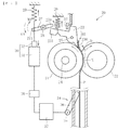
まず、図1に基づいて、本発明を適用する画像形成装置の全体構成について説明する。
図1は、本発明に係るカラー画像形成装置の概略構成図である。図1に示す画像形成装置本体100には、画像形成ユニットとしての4つのプロセスユニット1Y,1C,1M,1Bkが着脱可能に装着されている。各プロセスユニット1Y,1C,1M,1Bkは、カラー画像の色分解成分に対応するイエロー(Y)、シアン(C)、マゼンタ(M)、ブラック(Bk)の異なる色のトナーを収容している以外は同様の構成となっている。
First, the overall configuration of an image forming apparatus to which the present invention is applied will be described with reference to FIG.
FIG. 1 is a schematic configuration diagram of a color image forming apparatus according to the present invention. In the image forming apparatus
具体的には、各プロセスユニット1Y,1C,1M,1Bkは、像担持体(潜像担持体)としてのドラム状の感光体2と、感光体2の表面を帯電させる帯電手段としての帯電ローラ3と、感光体2の表面にトナー(現像剤)を供給する現像手段としての現像装置4と、感光体2の表面をクリーニングするクリーニング手段としてのクリーニングブレード5を備えている。なお、図1では、イエローのプロセスユニット1Yが備える感光体2、帯電ローラ3、現像装置4、クリーニングブレード5のみに符号を付しており、その他のプロセスユニット1C,1M,1Bkにおいては符号を省略している。
Specifically, each of the
各プロセスユニット1Y,1C,1M,1Bkの上方には、感光体2の表面を露光する露光手段(静電潜像形成手段)としての露光装置6が配設されている。露光装置6は、光源、ポリゴンミラー、f−θレンズ、反射ミラー等を有し、画像データに基づいて各感光体2の表面へレーザ光を照射するようになっている。
Above each of the
また、各プロセスユニット1Y,1C,1M,1Bkの下方には、転写装置7が配設されている。転写装置7は、転写体としての無端状のベルトから構成される中間転写ベルト8を有する。中間転写ベルト8は、支持部材としての駆動ローラ9と従動ローラ10に張架されており、駆動ローラ9が図の反時計回りに回転することによって、中間転写ベルト8は図の矢印に示す方向に周回走行(回転)するように構成されている。
A
4つの感光体2に対向した位置に、一次転写手段としての4つの一次転写ローラ11が配設されている。各一次転写ローラ11はそれぞれの位置で中間転写ベルト8の内周面を押圧しており、中間転写ベルト8の押圧された部分と各感光体2とが接触する箇所に一次転写ニップが形成されている。各一次転写ローラ11は、図示しない電源に接続されており、所定の直流電圧(DC)及び/又は交流電圧(AC)が一次転写ローラ11に印加されるようになっている。
Four
また、駆動ローラ9に対向した位置に、二次転写手段としての二次転写ローラ12が配設されている。この二次転写ローラ12は中間転写ベルト8の外周面を押圧しており、二次転写ローラ12と中間転写ベルト8とが接触する箇所に二次転写ニップが形成されている。二次転写ローラ12は、一次転写ローラ11と同様に、図示しない電源に接続されており、所定の直流電圧(DC)及び/又は交流電圧(AC)が二次転写ローラ12に印加されるようになっている。
A
また、中間転写ベルト8の図の右端側の外周面には、中間転写ベルト8の表面をクリーニングするベルトクリーニング装置13が配設されている。このベルトクリーニング装置13から伸びた図示しない廃トナー移送ホースは、転写装置7の下方に配設された廃トナー収容器14の入り口部に接続されている。
A
画像形成装置本体100の下部には、紙やOHP等のシート状の記録媒体Pを収容した給紙カセット15が配設されている。給紙カセット15には、収容されている記録媒体Pを送り出す給紙ローラ16が設けてある。一方、画像形成装置本体100の上部には、記録媒体を外部へ排出するための一対の排紙ローラ17と、排出された記録媒体をストックするための排紙トレイ18とが配設されている。
A
また、画像形成装置本体100内には、記録媒体Pを給紙カセット15から二次転写ニップを通って排紙トレイ18へ搬送するための搬送路Rが配設されている。搬送路Rにおいて、二次転写ローラ12の位置よりも記録媒体搬送方向上流側には一対のレジストローラ19が配設されている。また、二次転写ローラ12の位置よりも記録媒体搬送方向下流側には、定着装置20が配設されている。
Further, a conveyance path R for conveying the recording medium P from the
定着装置20は、加熱源によって加熱される定着部材としての定着ローラ21と、その定着ローラ21に当接して定着ニップを形成する対向部材としての加圧ローラ22と、定着ローラ21から記録媒体を分離させる分離部材23等を有する。本実施形態では、定着ローラ21と加圧ローラ22が図示しない加圧手段によって互いに圧接されることにより、圧接箇所において定着ニップが形成されているが、この構成に限定されるものではない。例えば、定着部材と対向部材の少なくとも一方を無端状ベルトとし、そのベルトをローラ又はパッド等によって相手側に圧接させる構成としてもよい。また、定着部材と対向部材は、互いに圧接する場合に限らず、加圧を行わす単に接触させるだけの構成とすることも可能である。
The fixing
以下、図1を参照して上記画像形成装置の基本的動作について説明する。
作像動作が開始されると、各プロセスユニット1Y,1C,1M,1Bkの感光体2が図示しない駆動装置によって図の時計回りに回転駆動され、各感光体2の表面が帯電ローラ3によって所定の極性に一様に帯電される。帯電された各感光体2の表面には、露光装置6からレーザ光がそれぞれ照射されて、それぞれの感光体2の表面に静電潜像が形成される。このとき、各感光体2に露光する画像情報は所望のフルカラー画像をイエロー、シアン、マゼンタ及びブラックの色情報に分解した単色の画像情報である。このように感光体2上に形成された静電潜像に、各現像装置4によってトナーが供給されることにより、静電潜像はトナー画像(現像剤像)として可視像化される。
The basic operation of the image forming apparatus will be described below with reference to FIG.
When the image forming operation is started, the
駆動ローラ9が図の反時計回りに回転駆動されることにより、中間転写ベルト8が図の矢印で示す方向に走行駆動される。また、各一次転写ローラ11に、トナーの帯電極性と逆極性の定電圧又は定電流制御された電圧が印加される。これにより、各一次転写ローラ11と各感光体2との間の一次転写ニップにおいて転写電界が形成される。そして、各プロセスユニット1Y,1C,1M,1Bkの感光体2に形成された各色のトナー画像が、上記一次転写ニップにおいて形成された転写電界によって、中間転写ベルト8上に順次重ね合わせて転写される。かくして中間転写ベルト8はその表面にフルカラーのトナー画像を担持する。また、中間転写ベルト8に転写しきれなかった各感光体2上のトナーは、クリーニングブレード5によって除去される。そして、図示しない除電手段によって、感光体2の表面が除電され、その表面電位が初期化されて次の画像形成に備えられる。
By driving the
また、作像動作が開始されると、給紙ローラ16が回転して、給紙カセット15から記録媒体Pが送り出される。送り出された記録媒体Pは、レジストローラ19によってタイミングを計られて、二次転写ローラ12と中間転写ベルト8との間の二次転写ニップに送られる。このとき二次転写ローラ12には、中間転写ベルト8上のトナー画像のトナー帯電極性と逆極性の転写電圧が印加されており、これにより、二次転写ニップに転写電界が形成されている。そして、二次転写ニップに形成された転写電界によって、中間転写ベルト8上のトナー画像が記録媒体P上に一括して転写される。その後、記録媒体Pは定着装置20へと搬送され、定着ローラ21と加圧ローラ22によって記録媒体Pが加熱及び加圧されてトナー画像が定着される。トナー画像が定着された記録媒体Pは、分離部材23によって定着ローラ21から分離され、排紙ローラ17によって排紙トレイ18へと排出される。また、転写後の中間転写ベルト8上に残留するトナーは、ベルトクリーニング装置13によって除去され、除去されたトナーは、廃トナー収容器14へ搬送され回収される。
When the image forming operation is started, the
以上の説明は、記録媒体上にフルカラー画像を形成するときの画像形成動作であるが、4つのプロセスユニット1Y,1C,1M,1Bkのいずれか1つを使用して単色画像を形成したり、2つ又は3つのプロセスユニットを使用して、2色又は3色の画像を形成したりすることも可能である。
The above description is an image forming operation when a full-color image is formed on a recording medium. A single-color image is formed using any one of the four
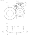
図2は、本実施形態に係る定着装置の斜視図である。
図2に示すように、本実施形態に係る定着装置20には、定着ローラ21の軸方向に渡って4つの分離部材23a〜23d設けられている。ただし、分離部材23の個数は、4つに限定されるものではない。各分離部材23a〜23dは支点(支軸)25a〜25dを中心に上下方向に回転可能に支持されており、これにより各分離部材23a〜23dの先端が定着ローラ21に対して接離可能となっている。ここでは、各分離部材23の先端は定着ローラ21に対して(互いに独立して)当接離間するようになっている。
FIG. 2 is a perspective view of the fixing device according to this embodiment.
As shown in FIG. 2, the fixing
また、各分離部材23a〜23dに対応して、分離部材23a〜23dの定着ローラ21への当接を解除する4つの当接解除部材27a〜27dが設けられている。4つの当接解除部材27a〜27dのうち、定着ローラ21の軸方向両端側に配設された2個の当接解除部材27a,27dは、支点(支軸)28aを中心に回転可能に支持されている。一方、定着ローラ21の軸方向中央部側に配設された2個の当接解除部材27b,27cは、別の支点(支軸)28bを中心として回転可能に支持されている。
Further, four
以下、図3、図4に基づいて、本実施形態に係る定着装置と分離部材の接離機構について詳しく説明する。なお、上記4つの分離部材23a〜23d及びそれらの接離機構は、基本的に同様の構成であるので、説明を簡略化するため1個の分離部材とその接離機構についてのみ説明する。
The contact / separation mechanism between the fixing device and the separation member according to this embodiment will be described in detail below with reference to FIGS. The four
図3又は図4に示すように、定着装置20が有する定着ローラ21は、内部に配設された加熱源24によって加熱されるようになっている。そして、この加熱源24によって定着ローラ21が所定の目標温度まで加熱された状態で、未定着画像を担持した記録媒体Pが、図の矢印の方向に回転する定着ローラ21と加圧ローラ22との間の定着ニップNに進入することにより、記録媒体P上のトナーが溶融され、画像が定着される。
As shown in FIG. 3 or FIG. 4, the fixing
定着ローラ21は、熱伝導性基体の周囲に弾性層を形成し、さらに被覆層で被覆された円筒状部材である。熱伝導性基体としては、所要の機械的強度を有し、熱伝導性の良好な炭素鋼材やアルミニウム材が主として用いられる。また、弾性層は、例えばシリコーンゴムやフッ素ゴム等の合成ゴムで形成される。さらに、弾性層の外側(外周面)の被覆層は、トナーとの離型性を良好とすると共に、弾性層の耐久性を高めるためのもので、熱伝導率が高く耐熱性に富む材料で形成される。例えば、フッ素樹脂(PFA)チューブで被覆したもの、フッ素樹脂(PFA又はPTFE)塗料を塗布したもの、あるいはシリコーンゴム層やフッ素ゴム層を形成したもの等が被覆層として用いられる。
The fixing
加圧ローラ22は、芯金、その芯金の外側(外周)に形成された弾性層、及び弾性層を被覆する被覆層から成る円筒状部材である。芯金として、例えばSTKM等が用いられ、弾性層として、シリコーンゴムやフッ素ゴム、あるいはこれらの発泡体が用いられる。被覆層は例えば離型性に富むPFA,PTFA等の耐熱性フッ素樹脂のチューブで形成される。
The
また、定着ローラ21の周囲には、図示しない温度検知手段としてのサーミスタや、異常温度防止用のサーモスタット等が配設され、サーミスタからの検出信号により、定着ローラ21の表面温度は所定の温度域内に維持されるように制御されている。
Further, a thermistor as a temperature detecting means (not shown), a thermostat for preventing abnormal temperature, and the like are disposed around the fixing
定着ニップNよりも記録媒体搬送方向の下流側(図3又は図4の上側)には、分離部材23が定着ローラ21に対向して配設されている。分離部材23は、支点25を中心に互いに独立して回転可能に支持されている。図3は分離部材23の先端230が定着ローラ21に対して離間している状態を示し、図4は分離部材23の先端230が定着ローラ21に対して当接している状態を示す。
A
また、図4において、定着ニップNの出口(記録媒体搬送方向の下流端部)から、分離部材23の先端230が定着ローラ21に当接する当接位置までの距離Dは、本実施形態では5mm〜6mmに設定している。また、定着ニップNの出口から排出される記録媒体Pの挙動を確認し、記録媒体Pが定着ローラ21の表面から最も離間する位置で、分離部材23の先端230が当接するように上記距離Dを設定することにより、分離部材23が記録媒体Pを分離する際に生じる負荷を低減することができ、記録媒体Pへのダメージを小さくすることが可能となる。
In FIG. 4, the distance D from the exit of the fixing nip N (downstream end in the recording medium conveyance direction) to the contact position where the
分離部材23の素材としては、主にPFAやPEK、PEEK等の離型性や摺動性の良い材料を用いられる。また、分離部材23の表面をPFAやテフロン(登録商標)離型性や摺動性の良い材料でコーティングしてもよい。
As a material of the
分離部材23の先端230とは反対側の基端231側には、当接方向付勢手段26が配設されている。本実施形態では、当接方向付勢手段26として引張コイルバネを用いているが、設置スペースや製造コストなどの諸条件に応じて、その他の付勢手段を当接方向付勢手段26として用いることも可能である。この当接方向付勢手段26によって、分離部材23は定着ローラ21に対して当接させる方向に付勢されている。
An abutting direction biasing means 26 is disposed on the
また、分離部材23の基端231側には、分離部材23の定着ローラ21への当接を解除可能な当接解除部材27が配設されている。当接解除部材27は、支点28を中心に回転可能に支持されている。当接解除部材27が支点28を中心に図の時計回り又は反時計回りに回転することにより、当接解除部材27の分離部材23側の先端270は分離部材23の基端231に対して接近離間するようになっている。当接解除部材27は、定着ローラ21の軸方向と平行な方向に渡って延在しており、複数の分離部材23の全てに対して当接可能に構成されている。
Further, on the
当接解除部材27の素材としては、軽量でかつ所要の機械的強度を有するPPSやPEK等の耐熱や耐摩耗性に優れた樹脂材量を用いることができる。本実施形態では、当接解除部材27の軸方向(長手方向)に渡る撓み防止の観点から、特に支点28となる回転軸部分をSUS材にて別体で形成しているが、装置の大きさや分離部材23への付勢力に応じて材料選定を行うことが望ましい。
As a material of the
当接解除部材27に駆動連結された図示しないリンク部材には、分離部材23を定着ローラ21に対して離間させるように当接解除部材27を付勢する当接解除方向付勢手段29が配設されている。なお、図3、図4においては、模式的に当接解除部材27の基端271に当接解除方向付勢手段29を配設している。当接解除方向付勢手段29により当接解除部材27の基端271が引っ張られることによって、当接解除部材27の先端270は分離部材23の基端231に当接する方向に付勢されている。なお、設置スペースや製造コストなどの諸条件に応じて、その他の付勢手段を当接解除方向付勢手段29として用いることも可能である。
The link member (not shown) that is drivingly connected to the
また、当接解除部材27を駆動させる駆動手段としてソレノイド30が配設されている。ソレノイド30は、コイルを内蔵するソレノイド本体31と、前記コイル内で進退可能に装着されたプランジャ32を有する。進退可能なプランジャ32は、当接解除部材27に駆動連結された図示しないリンク部材に連結されている。なお、図3、図4においては、模式的に当接解除部材27の基端271にプランジャ32を連結させている。そして、ソレノイド本体31内のコイルが励磁され、プランジャ32がソレノイド本体31内へ吸引されて後退することにより、当接解除部材27が駆動(回転)されるようになっている。
Further, a
分離部材23の図の上側には、分離部材23を所定の離間位置に位置決めする位置決め手段33が設けてある。このように、位置決め手段33を設けることにより、部品寸法のばらつきや部品組付けのばらつきがあっても、分離部材23を定着ローラ21の表面に対して適切な離間量をもって保持可能となっている。
Positioning means 33 for positioning the
定着ニップNよりも記録媒体搬送方向の上流側(図3又は図4の下側)には、記録媒体Pを検知する記録媒体検知手段34が配設されている。記録媒体検知手段34は、支点35を中心に揺動(又は回転)可能に支持された検知部36を有する。通常、検知部36は記録媒体Pの搬送路Rに交差した位置に配設されており(図3参照)、搬送される記録媒体Pが検知部36に接触することで検知部36が揺動し(図4参照)、記録媒体Pを検知する仕組みとなっている。また、記録媒体Pの通過後、検知部36は、自重又は図示しない捩りコイルバネ等の付勢手段によって元の位置に戻り、図示しない位置決め部に当接して図2に示す所定の位置に保持されるようになっている。
A recording
記録媒体Pが検知部36と接触することによって記録媒体Pの搬送姿勢に傾き(スキュー)が生じないように、検知部36は搬送路Rの幅方向中央近傍に配設することが好ましい。このように検知部36を配設することで、記録媒体Pを正しい姿勢で搬送することができ、画像の歪みや紙シワの発生などを防止して搬送信頼性を確保できる。
The
また、記録媒体検知手段34を、上記のような記録媒体に接触することによって記録媒体を検知する接触式検知手段でなく、記録媒体に接触せずに記録媒体を検知する非接触式検知手段とすることも可能である。非接触式検知手段としては、例えば、反射型や透過型の光センサを用いることができる。非接触式検知手段を用いた場合は、記録媒体Pの搬送姿勢に傾き(スキュー)が生じる虞はない。
Further, the recording
また、定着ニップNの記録媒体搬送方向の上流側で記録媒体の詰まりの発生を検知する詰まり検知手段を設けている場合は、これを記録媒体検知手段34として兼用してもよい。この場合は、記録媒体を検知するための専用の検知手段を設ける必要がなくなるので、装置の小型化や低コスト化を図れる。
Further, when a clogging detection unit that detects occurrence of clogging of the recording medium is provided on the upstream side of the fixing nip N in the recording medium conveyance direction, this may be used as the recording
上記ソレノイド30は、記録媒体検知手段34の検知信号に基づいて駆動されるように構成されている。詳しくは、ソレノイド30と記録媒体検知手段34とが、制御部37及び駆動回路38を介して電気的に接続されている。前記制御部37は、内部にI/Oポートを有するCPUである。搬送される記録媒体Pが記録媒体検知手段34によって検知されると、その検知信号に基づいて制御部37は駆動回路38を介してソレノイド30を駆動させるように構成されている。
The
図3に示す分離部材23が定着ローラ21から離間している状態では、ソレノイド30に駆動力は生じておらず、当接解除部材27はソレノイド30からの力は受けない。この場合、当接解除部材27は、当接解除方向付勢手段29からの付勢力を受けている。詳しくは、当接解除方向付勢手段29によって当接解除部材27の基端271が図の上方に引っ張られていることにより、当接解除部材27には図の時計回り方向の力(回転モーメントM3)が作用している。この時計回り方向の力(回転モーメントM3)が作用することによって、当接解除部材27の先端270は、分離部材23の基端231を図の下方に押圧した状態となっている。
In the state where the
当接解除部材27が分離部材23の基端231を図の下方に押圧していることにより、分離部材23には図の反時計回り方向の力(回転モーメントM2)が作用している。他方、当接方向付勢手段26によって分離部材23の基端231が図の上方に引っ張られていることにより、分離部材23には時計回り方向の力(回転モーメントM1)が作用している。このように、分離部材23には互いに逆向きの力(回転モーメントM1と回転モーメントM2)が作用しているが、ここでは反時計回り方向の力(回転モーメントM2)の方が時計回方向の力(回転モーメントM1)よりも大きいため、分離部材23の先端230は定着ローラ21から離間した状態となっている。
Since the
また、図4に示す分離部材23が定着ローラ21に当接した状態では、ソレノイド30に所定の電流が印加されることにより、プランジャ32が吸引されソレノイド本体31内へ後退する。これにより、当接解除部材27の基端271は図の下方に引っ張られ、当接解除部材27には図の反時計回り方向の力(回転モーメントM4)が作用する。他方、当接解除部材27には当接解除方向付勢手段29によって上記時計回り方向の力(回転モーメントM3)が作用しているが、この時計回り方向の力(回転モーメントM3)よりも、上記ソレノイド30による反時計回り方向の力(回転モーメントM4)の方が大きいので、当接解除部材27は図の反時計回りに回転する。その結果、当接解除部材27の先端270が分離部材23の基端231から離間し、当接解除部材27による分離部材23の押圧が解除される。
In the state where the
当接解除部材27による分離部材23の押圧が解除されると、分離部材23には当接方向付勢手段26による上記時計回り方向の力(回転モーメントM1)のみが作用することになるため、分離部材23は図の時計回り方向に回転して、それぞれの先端230が定着ローラ21に当接する。そして、定着ニップNを通過した記録媒体Pが、分離部材23によって定着ローラ21から分離される。
When the pressing of the
その後、ソレノイド30に印加されていた電流が遮断されることにより、プランジャ32の吸引力が解除されると、再び当接解除部材27は当接解除方向付勢手段29からの力(回転モーメントM3)によって分離部材23を押圧する。そして、その押圧力によって、分離部材23に再び図の反時計回り方向の力(回転モーメントM2)が作用する。上述したように、分離部材23に作用する反時計回り方向の力(回転モーメントM2)は、当接方向付勢手段26によって各分離部材23に作用する上記時計回り方向の力(回転モーメントM1)よりも大きいので、分離部材23は図の反時計回りに回転し、それぞれの先端230が定着ローラ21から離間して図3の状態に戻る。
After that, when the current applied to the
以下、本発明の特徴部分について説明する。
本発明に係る定着装置では、記録媒体のカールを矯正するために分離部材を用いる。すなわち、本発明は、上記のように分離部材23によって定着ローラ21から記録媒体を分離する分離モードと、分離部材23によって記録媒体のカールを矯正するカール矯正モードを有している。さらに、本実施形態では、図5(a)(b)(c)に示す3種類カールに応じて異なるカール矯正モードを設定している。図5において(a)は記録媒体Pの幅方向両端部が画像面側(定着ローラ21側)に曲がったカール、(b)は記録媒体Pの幅方向両端部が非画像面側(加圧ローラ22側)に曲がったカール、(c)は記録媒体Pの搬送方向先端部が画像面側(定着ローラ21側)に曲がったカールを示す。
Hereafter, the characteristic part of this invention is demonstrated.
In the fixing device according to the present invention, a separating member is used to correct the curl of the recording medium. In other words, the present invention has a separation mode in which the recording medium is separated from the fixing
図6(a)は、上記分離モードの状態の定着装置の側面図、同図の(b)は、それを上方から見た平面図である。
分離モードの場合は、4つの分離部材23a〜23dの全てを定着ローラ21に当接させる。これにより、定着ニップを通過した記録媒体Pは分離部材23a〜23dによって定着ローラ21から分離される。
6A is a side view of the fixing device in the separation mode, and FIG. 6B is a plan view of the fixing device as viewed from above.
In the separation mode, all of the four
図7(a)は、上記図5(a)に示すカールを除去するためのカール除去モードの状態の定着装置の側面図、同図の(b)は、それを上方から見た平面図である。
このカール除去モードの場合は、4つの分離部材23a〜23dのうち、記録媒体Pの幅方向両端部側に位置する分離部材23a,23dのみを定着ローラ21から離間させ、それらの分離部材23a,23dによって記録媒体Pの幅方向両端部側を非画像面側(加圧ローラ22側)に押す。これにより、記録媒体Pの幅方向両端部がカールする方向とは反対側に曲げられるので、カールが矯正される。
FIG. 7A is a side view of the fixing device in the curl removal mode for removing the curl shown in FIG. 5A, and FIG. 7B is a plan view of the fixing device as viewed from above. is there.
In the curl removal mode, among the four
図8(a)は、上記図5(b)に示すカールを除去するためのカール除去モードの状態の定着装置の側面図、同図の(b)は、それを上方から見た平面図である。
このカール除去モードの場合は、4つの分離部材23a〜23dのうち、記録媒体Pの幅方向中央部側に位置する分離部材23b,23cのみを定着ローラ21から離間させ、それらの分離部材23b,23cによって記録媒体Pの幅方向中央部側を非画像面側(加圧ローラ22側)に押す。これにより、記録媒体Pの幅方向中央部がカールする方向とは反対側に曲げられ、カールが矯正される。
8A is a side view of the fixing device in the curl removal mode for removing the curl shown in FIG. 5B, and FIG. 8B is a plan view of the fixing device as viewed from above. is there.
In the curl removal mode, among the four
図9(a)は、上記図5(c)に示すカールを除去するためのカール除去モードの状態の定着装置の側面図、同図の(b)は、それを上方から見た平面図である。
このカール除去モードの場合は、4つの分離部材23a〜23dの全てを定着ローラ21から離間させ、それらの分離部材23a〜23dによって記録媒体Pの幅方向全体に渡って(幅方向中央部側と両端部側)を非画像面側(加圧ローラ22側)に押す。これにより、記録媒体Pがカールする方向とは反対側に曲げられ、カールが矯正される。
FIG. 9A is a side view of the fixing device in the curl removal mode for removing the curl shown in FIG. 5C, and FIG. 9B is a plan view of the fixing device viewed from above. is there.
In this curl removal mode, all of the four
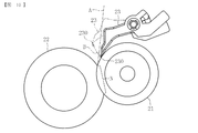
図10、図11は、分離部材の接離動作範囲を説明するための図である。
図10において、一点鎖線Aは、記録媒体が分離部材23によって定着ローラ21から分離された直後の定着ニップNからの記録媒体の排出経路(以下、便宜的に「分離直後の排出経路」という。)、同図中の一点鎖線Bは、分離部材23の先端230の移動軌跡である。図10に示すように、分離部材23の先端230の移動軌跡Bは、分離直後の排出経路Aと交差している。このように、分離部材23の先端230の移動軌跡Bが分離直後の排出経路Aと交差するように、分離部材23の先端位置及びその離間距離を設定しているため、分離部材23の先端230によって定着ニップ通過後の記録媒体を押すことが可能となっている。また、本実施形態では、定着ローラ21の外径を24mm〜26mm、加圧ローラ22の外径を30mm〜32mmとしており、分離部材23の先端230と定着ニップNの出口部との距離は5mm〜6mmに設定している。なお、分離部材23の先端230と定着ニップNの出口部との距離は、定着ローラ21又は加圧ローラ22の外径、硬度差等に応じて適宜設定すればよい。
10 and 11 are views for explaining the contact / separation operation range of the separation member.
In FIG. 10, an alternate long and short dash line A is a discharge path of the recording medium from the fixing nip N immediately after the recording medium is separated from the fixing
また、図11において、一点鎖線Cは、定着ニップNの出口部と排紙ローラ対17のニップの入口部とを結んだ直線(以下、便宜的に「ニップ間の直線」という。)であり、同図中の一点鎖線Bは、上記と同様の分離部材23の先端の移動軌跡である。図11に示すように、分離部材23の先端の移動軌跡Bは、ニップ間の直線Cと交差している。このように、分離部材23の先端の移動軌跡Bがニップ間の直線Cと交差するように構成されていることで、定着ニップNと排紙ローラ対17のニップ間で記録媒体が張られた状態で搬送される際にも、分離部材23の先端によって記録媒体を押すことが可能となっている。
In FIG. 11, an alternate long and short dash line C is a straight line connecting the exit portion of the fixing nip N and the entrance portion of the nip of the paper discharge roller pair 17 (hereinafter referred to as “straight line between nips” for convenience). The alternate long and short dash line B in the figure is the movement locus of the tip of the
なお、記録媒体を押す分離部材23の箇所は、先端以外の部分であってもよい。例えば、分離部材23の先端近傍に凸部を設け、その凸部によって記録媒体を押すようにすることも可能である。従って、分離部材23が定着ローラ21から離間した際に分離部材23が記録媒体に接触する接触部の移動軌跡が、上記記録媒体の排出経路A又は上記ニップ間を結ぶ搬送経路Cと交差すればよい。
The part of the separating
図12は、本実施形態の定着装置における記録媒体の分離処理及びカール矯正処理の制御を示すフローチャートである。
まず、印刷開始後、全ての分離部材を定着ローラに当接させて、分離モード(図6に示す状態)へと移行する。その後、未定着画像を担持した記録媒体が定着ニップを通過して画像が定着された後、分離部材によって記録媒体の先端が定着ローラから分離される。そして、記録媒体の先端を分離した直後に、複数の分離部材の一部又は全てを定着ローラから離間させて、記録媒体に生じるカールの種類に応じたカール矯正モード(図7〜図9に示す状態のいずれか)へと移行する。そして、定着ローラから離間した分離部材によって記録媒体のカールする方向とは反対方向に記録媒体が押されてカールが矯正された後、記録媒体は機外へと排出され印刷が終了する。
FIG. 12 is a flowchart showing the control of the recording medium separation process and the curl correction process in the fixing device of this embodiment.
First, after printing is started, all the separating members are brought into contact with the fixing roller, and a transition is made to a separation mode (state shown in FIG. 6). Thereafter, after the recording medium carrying the unfixed image passes through the fixing nip and the image is fixed, the leading end of the recording medium is separated from the fixing roller by the separation member. Then, immediately after separating the leading edge of the recording medium, some or all of the plurality of separating members are separated from the fixing roller, and a curl correction mode corresponding to the type of curl generated on the recording medium (shown in FIGS. 7 to 9). One of the states). Then, after the recording medium is pushed in the direction opposite to the curling direction of the recording medium by the separating member separated from the fixing roller to correct the curl, the recording medium is discharged to the outside of the apparatus and printing is finished.
上記カールの種類の判断は、記録媒体のサイズや種類、周辺温湿度等の情報を取得することにより判断する。なお、これらの情報とカールの種類との関係を示す制御テーブルを、事前に実験等を通じて用意しておくことが望ましい。また、カール矯正モードへと移行するタイミングは、定着ニップの記録媒体搬送方向の上流側に配設された記録媒体検知手段34によって記録媒体が検知されるタイミングから一定時間後に、記録媒体の先端が分離部材に到達したとして、これに基づき判断する。
The curl type is determined by acquiring information such as the size and type of the recording medium and the ambient temperature and humidity. Note that it is desirable to prepare a control table indicating the relationship between these pieces of information and the curl type in advance through experiments or the like. Further, the timing of shifting to the curl correction mode is such that the front end of the recording medium is fixed after a certain time from the timing when the recording medium is detected by the
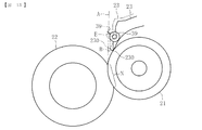
図13、図14は、本発明の定着装置の他の実施形態の構成を示す図である。
図13に示すように、この実施形態では、分離部材23の先端230近傍にコロ39を回転可能に設けている。また、図13において、一点鎖線Eは、分離部材23が定着ローラ21から離間した際にコロ39が記録媒体に接触する接触部の移動軌跡である。なお、 同図中の一点鎖線Aは、上記と同様の分離直後の排出経路であり、一点鎖線Bは、上記と同様の分離部材23の先端230の移動軌跡である。図13に示すように、コロ39の接触部の移動軌跡Eは、分離直後の排出経路Aと交差するように構成されている。これにより、分離部材23が定着ローラ21から離間した際にコロ39によって定着ニップNから排出された記録媒体を押すことができるようになっている。一方、分離部材23の先端230の移動軌跡Bは、分離直後の排出経路Aと交差しないように構成している。従って、この実施形態では、定着ローラ21から分離後の記録媒体に対して、分離部材23の先端230は接触しないようになっている。
13 and 14 are diagrams showing the configuration of another embodiment of the fixing device of the present invention.
As shown in FIG. 13, in this embodiment, a
また、図14において、一点鎖線E、B、Cは、それぞれ上記と同様のコロ39の接触部の移動軌跡、分離部材23の先端の移動軌跡、ニップ間の直線である。図14に示すように、この実施形態では、コロ39の接触部の移動軌跡Eは、ニップ間の直線Cと交差するように構成されているので、定着ニップNと排紙ローラ対17のニップ間で記録媒体が張られた状態で搬送される際にも、コロ39によって記録媒体を押すことが可能となっている。一方、分離部材23の先端の移動軌跡Bは、ニップ間の直線Cと交差していないので、定着ニップNと排紙ローラ対17のニップ間で記録媒体が張られた状態で搬送される際、分離部材23の先端は記録媒体に接触しないようになっている。
In FIG. 14, alternate long and short dash lines E, B, and C are the movement locus of the contact portion of the
上記のように構成されていることで、図13及び図14に示す実施形態では、定着ローラ21から分離された後の記録媒体を、分離部材23の先端ではなく回転可能なコロ39によって押すことができる。これにより、記録媒体に傷をつけることなくカールを矯正することが可能となる。ただし、分離部材23の先端で記録媒体を押す構成の方が、コロ39で記録媒体を押す構成よりも、定着ニップNから近い位置、すなわち記録媒体の温度がより高くクセの付きやすい状態で押すことができるため、カール矯正力を一層効果的に発揮できる点で優れている。従って、いずれの実施形態を選択するかについては、カール矯正力と分離部材の先端が接触することによる記録媒体の傷の度合いを考慮して決定すればよい。なお、図13及び図14に示す実施形態において、上記説明した点以外は、図1〜図12を用いて説明した実施形態と同様であるので説明を省略する。
13 and 14, the recording medium separated from the fixing
以上のように、本発明の各実施形態によれば、分離部材23を定着ローラ21から離間させることにより、分離部材23(又はそれに設けたコロ39)によって記録媒体をカールした方向とは反対方向に押すことができるので、記録媒体のカールを効果的に矯正することが可能である。すなわち、本発明の各実施形態では、従来に比べて、定着ニップに近い位置で記録媒体を押すことができるので、記録媒体の温度が高くクセのつきやすい状態で記録媒体のカールを矯正することができる。しかも、既存の分離部材を用いてカール矯正を行うことができるため、専用のカール矯正手段を設ける必要がなくなり、装置の小型化や低コスト化を図ることもできる。また、複数の分離部材23のうち、定着ローラ21から離間させる分離部材23を適宜変更することにより、カールの種類に応じてカール矯正を行うことが可能である。
As described above, according to each embodiment of the present invention, by separating the
また、本実施形態では、複数の分離部材23a〜23dを一体的に接離可能に構成するのではなく、それぞれ独立して接離可能に構成しているので、各分離部材23a〜23dの寸法誤差や定着ローラ21の撓みや振れ等があっても、全ての分離部材23a〜23dを定着ローラ21の表面に確実に当接させることができ、良好な分離性を安定して得られる。また、本実施形態に係る定着装置20は、複数の分離部材23a〜23dに当接する当接解除部材27を設けていることにより、1つの駆動手段(ソレノイド30)によって複数の分離部材23a〜23dを一様に接離操作することができる。このため、複数の分離部材23a〜23dを駆動させるために、駆動手段を複数設ける必要がないので、各分離部材23a〜23dの接離動作の信頼性が向上すると共に、装置の小型化及び低コスト化を図れる。
Further, in the present embodiment, the plurality of
また、図4に示すように、分離部材23が定着ローラ21に対して当接している状態では、当接解除部材27を分離部材23に接触させないことにより、分離部材23は当接解除部材27の影響を受けずに当接方向付勢手段26の付勢力のみによって定着ローラ21に当接する。これにより、分離部材23を定着ローラ21に対して適切な当接圧で当接させることが可能である。
As shown in FIG. 4, when the
また、本実施形態では、分離部材23を定着ローラ21に当接させるときのみソレノイド30を駆動すればよい。一般に分離部材23が定着ローラ21に当接している時間は離間している時間に比べ短いため、分離部材23を当接させるときのみソレノイド30を駆動させる構成とすることで、ソレノイド30の通電率を低減させ、自己発熱によるプランジャ32の駆動力低下を抑制することが可能である。
In this embodiment, the
なお、本発明は上述の実施形態に限定されるものではなく、本発明の要旨を逸脱しない範囲で種々の変更を加え得ることは勿論である。また、本発明に係る定着装置を搭載する画像形成装置は、図1に示すカラー画像形成装置に限らず、その他の複写機、プリンタ、ファクシミリ、あるいはこれらの複合機等であってもよい。 In addition, this invention is not limited to the above-mentioned embodiment, Of course, a various change can be added in the range which does not deviate from the summary of this invention. Further, the image forming apparatus equipped with the fixing device according to the present invention is not limited to the color image forming apparatus shown in FIG. 1, but may be other copiers, printers, facsimiles, or complex machines thereof.
20 定着装置
21 定着ローラ(定着部材)
22 加圧ローラ(対向部材)
23 分離部材
39 コロ
A 分離直後の排出経路
B 分離部材の先端の移動軌跡
C ニップ間の直線
E コロの接触部の移動軌跡
P 記録媒体
20
22 Pressure roller (opposing member)
23
Claims (11)
前記定着ニップを通過した記録媒体を、前記定着部材から離間させた前記分離部材によって当該記録媒体のカールした方向とは反対方向に押すように構成したことを特徴とする定着装置。 A fixing member heated by a heating source; an opposing member that contacts the fixing member to form a fixing nip; and a separation member that separates the recording medium that contacts the fixing member and passes through the fixing nip from the fixing member. A fixing device configured to be able to contact and separate the fixing member with respect to the fixing member;
A fixing device, wherein the recording medium that has passed through the fixing nip is configured to be pushed in a direction opposite to a curled direction of the recording medium by the separating member that is separated from the fixing member.
Priority Applications (1)
| Application Number | Priority Date | Filing Date | Title |
|---|---|---|---|
| JP2010290447A JP2012137652A (en) | 2010-12-27 | 2010-12-27 | Fixing device and image forming apparatus |
Applications Claiming Priority (1)
| Application Number | Priority Date | Filing Date | Title |
|---|---|---|---|
| JP2010290447A JP2012137652A (en) | 2010-12-27 | 2010-12-27 | Fixing device and image forming apparatus |
Publications (1)
| Publication Number | Publication Date |
|---|---|
| JP2012137652A true JP2012137652A (en) | 2012-07-19 |
Family
ID=46675108
Family Applications (1)
| Application Number | Title | Priority Date | Filing Date |
|---|---|---|---|
| JP2010290447A Pending JP2012137652A (en) | 2010-12-27 | 2010-12-27 | Fixing device and image forming apparatus |
Country Status (1)
| Country | Link |
|---|---|
| JP (1) | JP2012137652A (en) |
Cited By (1)
| Publication number | Priority date | Publication date | Assignee | Title |
|---|---|---|---|---|
| JP2017027005A (en) * | 2015-05-07 | 2017-02-02 | 株式会社リコー | Image forming apparatus |
-
2010
- 2010-12-27 JP JP2010290447A patent/JP2012137652A/en active Pending
Cited By (1)
| Publication number | Priority date | Publication date | Assignee | Title |
|---|---|---|---|---|
| JP2017027005A (en) * | 2015-05-07 | 2017-02-02 | 株式会社リコー | Image forming apparatus |
Similar Documents
| Publication | Publication Date | Title |
|---|---|---|
| US8903275B2 (en) | Fixing device and image forming apparatus incorporating same | |
| JP5776186B2 (en) | Fixing apparatus and image forming apparatus | |
| JP5835646B2 (en) | Guide device, fixing device, and image forming apparatus | |
| JP5822062B2 (en) | Guide mechanism, fixing device, and image forming apparatus | |
| US8909074B2 (en) | Fixing device and image forming apparatus including same | |
| JP5936333B2 (en) | Image heating apparatus and image forming apparatus | |
| US9389560B2 (en) | Fixing device including a separator to separate a recording medium from a pressure rotator and image forming apparatus including the fixing device | |
| JP2013015549A (en) | Fixing device and image forming device | |
| US20160274523A1 (en) | Image forming apparatus | |
| JP6485145B2 (en) | Fixing apparatus and image forming apparatus | |
| US9141056B2 (en) | Fixing device and image forming apparatus incorporating same | |
| JP2015075715A (en) | Fixing device and image forming apparatus | |
| JP2013024895A (en) | Fixing device and image formation device | |
| JP6112730B2 (en) | Fixing apparatus and image forming apparatus having the same | |
| JP6589507B2 (en) | Image forming apparatus | |
| JP2016177063A (en) | Image forming apparatus | |
| JP5610150B2 (en) | Fixing apparatus and image forming apparatus | |
| JP2012137652A (en) | Fixing device and image forming apparatus | |
| JP6032541B2 (en) | Fixing apparatus and image forming apparatus | |
| JP2017001879A (en) | Image formation apparatus | |
| JP6140633B2 (en) | Fixing apparatus and image forming apparatus | |
| JP5008907B2 (en) | Separation claw and fixing device having the same | |
| JP6169039B2 (en) | Image forming apparatus | |
| JP5418841B2 (en) | Fixing apparatus and image forming apparatus | |
| JP2013020106A (en) | Fixing device and image forming apparatus |