JP2012136885A - Method for manufacturing autoclaved lightweight concrete panel - Google Patents
Method for manufacturing autoclaved lightweight concrete panel Download PDFInfo
- Publication number
- JP2012136885A JP2012136885A JP2010290745A JP2010290745A JP2012136885A JP 2012136885 A JP2012136885 A JP 2012136885A JP 2010290745 A JP2010290745 A JP 2010290745A JP 2010290745 A JP2010290745 A JP 2010290745A JP 2012136885 A JP2012136885 A JP 2012136885A
- Authority
- JP
- Japan
- Prior art keywords
- reinforcing bar
- mesh
- reinforcing
- mat
- reinforcing member
- Prior art date
- Legal status (The legal status is an assumption and is not a legal conclusion. Google has not performed a legal analysis and makes no representation as to the accuracy of the status listed.)
- Granted
Links
Images


Abstract
Description
本発明は、主筋と副筋とを備えた補強筋マットとメタルラス等の網状補強部材とを埋設した軽量気泡コンクリートパネルの製造方法に関するものである。 The present invention relates to a method of manufacturing a lightweight cellular concrete panel in which a reinforcing bar mat having main bars and auxiliary bars and a net-like reinforcing member such as a metal lath are embedded.
従来、軽量気泡コンクリートパネル(以下、「ALCパネル」という)内に主筋と副筋とからなる補強筋マットとメタルラス等の網状補強部材とからなる補強筋構造を埋設したものが提案されている。 2. Description of the Related Art Conventionally, there has been proposed a structure in which a reinforcing bar structure including a reinforcing bar mat composed of main and auxiliary bars and a net-like reinforcing member such as a metal lath is embedded in a lightweight cellular concrete panel (hereinafter referred to as “ALC panel”).
建築物の壁、床または屋根に使用されたALCパネルには、給排水や冷暖房、換気などの設備等のために、大小さまざまな貫通孔や開口が空けられることが多い。一方、ALCパネルの内部には、パネルの曲げ強度を発現させるために多数の主筋や副筋が埋設されており、設備配管用の貫通孔の孔開けによって主筋や副筋を備えた補強筋マットが切断されてしまうと、パネル曲げ強度が低下する恐れがあるため、任意の位置に多数または大きな孔を設けることは困難であった。この課題を解決するALCパネルが、特開2010−59715号公報により提案されている。 ALC panels used for building walls, floors or roofs often have large and small through holes and openings for facilities such as water supply and drainage, air conditioning and ventilation. On the other hand, in the interior of the ALC panel, a large number of main bars and auxiliary bars are embedded in order to develop the bending strength of the panel, and reinforcing bar mats provided with main bars and auxiliary bars by drilling through holes for equipment piping If it is cut, there is a risk that the panel bending strength may be lowered. Therefore, it is difficult to provide a large number or large holes at arbitrary positions. An ALC panel that solves this problem is proposed in Japanese Patent Application Laid-Open No. 2010-59715.
また、ALCパネルの補強筋マットよりも外側の縁部に孔開けや切欠き加工等を行う際に欠けが生じ易いという課題を解決するALCパネルが、特開2010−77624号公報により提案されている。 Japanese Patent Application Laid-Open No. 2010-77624 proposes an ALC panel that solves the problem that chipping is likely to occur when perforating or notching the outer edge of the reinforcing bar mat of the ALC panel. Yes.
また、ALCパネルに穿孔する際、ドリル刃の切り抜け時に裏面側の母材が剥落する問題を解決するため、鉄筋から成る補強筋マットに金網を張設したALCパネルが実開平6−078432号公報により提案されている。 In order to solve the problem that the base material on the back side is peeled off when the drill blade is cut through when drilling the ALC panel, an ALC panel in which a reinforcing mesh made of reinforcing bars is stretched with a wire mesh is disclosed in Japanese Utility Model Laid-Open No. 6-077842. Has been proposed.
また、ALCパネルの意匠性や耐久性をより高める場合には、その表面を化粧板等の被覆板で覆うことが行われているが、その場合において保管及び運搬に支障をきたさず、施工に要する工数及び時間を著しく低減させるように工夫されたALCパネルが、特開平6−114822号公報により提案されている。 In order to further enhance the design and durability of the ALC panel, the surface is covered with a cover plate such as a decorative plate. In that case, the storage and transportation are not hindered, and the construction is performed. Japanese Patent Laid-Open No. 6-114822 has proposed an ALC panel devised to significantly reduce the man-hours and time required.
上述のALCパネルに利用される補強筋構造は、主筋と副筋とからなる補強筋マットに網状補強部材を直接接触させて固定することで製造されていると想定され、特に、その固定方法としては、両部材同士の溶接、あるいは網状補強部材の一部、または他の部材を利用した両部材同士の緊結などが考えられる。 It is assumed that the reinforcing bar structure used for the ALC panel described above is manufactured by directly contacting and fixing a mesh reinforcing member to a reinforcing bar mat composed of a main bar and a secondary bar. The two members can be welded together, or a part of the net-like reinforcing member, or the two members can be joined together using another member.
ALCパネルは、補強筋構造を形成した後、補強筋構造を軽量気泡コンクリートの原料スラリーで包囲し、さらに原料スラリーを発泡硬化することで製造される。ここで、補強筋構造には発錆を防止するための防錆処理が必要である。従って、ALCパネルの製造工程では、補強筋構造を原料スラリーで包囲する前に、補強筋構造に対して防錆処理を施している。この防錆処理は、一般的には防錆液が満たされた浸漬槽に、補強筋構造を完全に漬けて補強筋構造の表面に防錆液を付着させ、これを乾燥させることにより所望の厚みを持った防錆塗膜を形成することで実行される。 The ALC panel is manufactured by forming a reinforcing bar structure, surrounding the reinforcing bar structure with a raw slurry of lightweight cellular concrete, and further foam-curing the raw material slurry. Here, the reinforcing bar structure needs rust prevention treatment to prevent rusting. Therefore, in the manufacturing process of the ALC panel, the reinforcing bar structure is subjected to rust prevention treatment before the reinforcing bar structure is surrounded by the raw material slurry. This rust prevention treatment is generally performed by immersing the reinforcing bar structure completely in an immersion tank filled with the rust prevention liquid, attaching the rust prevention liquid to the surface of the reinforcing bar structure, and drying it. It is executed by forming a rust-proof coating film having a thickness.
従来のALCパネルに使用されている補強筋構造では、補強筋マットと網状補強部材とは互いに接触され、溶接などで部分的に固定されている。この種の補強筋構造では、両者の接触部位は実質的に防錆塗膜が形成されていない。ここで、ALCパネルの製造工程において、上述の原料スラリーの発泡硬化の際には補強筋構造に対して外部から応力が働き、接触部位が部分的に離れ、防錆塗膜に欠損を生じる可能性がある。一方で、防錆塗膜の欠損防止のために接触部位の全面に溶接を施したり、略全体を締結したりするなどの方策が考えられるが、そのような態様だとALCパネルの製造上、工程数の増大やコストの増大を招く結果になり、実用的ではない。 In the reinforcing bar structure used in the conventional ALC panel, the reinforcing bar mat and the net-like reinforcing member are in contact with each other and partially fixed by welding or the like. In this type of reinforcing bar structure, a rust-proof coating film is not substantially formed at the contact portion between the two. Here, in the manufacturing process of the ALC panel, when the above-mentioned raw material slurry is foam-cured, stress is applied to the reinforcing bar structure from the outside, the contact part is partially separated, and the anticorrosive coating film may be damaged. There is sex. On the other hand, in order to prevent the loss of the anticorrosive coating, measures such as performing welding on the entire surface of the contact part or fastening the substantially whole can be considered. This results in an increase in the number of processes and an increase in cost, which is not practical.
本発明は、以上の課題を解決することを目的としており、補強筋構造の防錆塗膜に生じる欠損を効果的に防止でき、高品質パネルの製造を可能にする軽量気泡コンクリートパネルの製造方法を提供することを目的とする。 The present invention aims to solve the above-mentioned problems, and can effectively prevent defects generated in a rust-preventing coating film having a reinforcing bar structure, and a method for producing a lightweight cellular concrete panel that enables the production of a high-quality panel. The purpose is to provide.
本発明は、補強筋マットを備えた補強筋構造を原料スラリーによってパネル状に包囲し、原料スラリーを発泡硬化させることで製造される軽量気泡コンクリートパネルの製造方法であって、補強筋マットと網状補強部材とを対向配置すると共に、取り付け部材を介して補強筋マットと網状補強部材とを離間させた状態で結合することによって補強筋構造を形成する補強筋構造形成工程を備えることを特徴とする。 The present invention relates to a lightweight cellular concrete panel manufacturing method in which a reinforcing bar structure provided with a reinforcing bar mat is surrounded by a raw material slurry in a panel shape, and the raw material slurry is foamed and cured. A reinforcing bar structure forming step of forming a reinforcing bar structure by arranging the reinforcing bar and the mesh reinforcing member in a separated state through the mounting member while arranging the reinforcing member to face each other. .
本発明では、補強筋マットと網状補強部材とが取り付け部材を介して離間された状態で結合され、その結果として補強筋構造が形成される。つまり、本発明では、前提として、補強筋マットと網状補強部材とが離間しているため、防錆処理を施した際に補強筋構造の略全面に渡って防錆塗膜が形成される。従って、原料スラリーの発泡硬化の際に補強筋構造に応力がかかり、例えば、補強筋マットと網状補強部材との離間幅が変化したとしても防錆塗膜の欠損とはならない。従って、本発明によれば、補強筋構造の防錆塗膜の欠損を効果的に防止でき、高品質の軽量気泡コンクリートパネルの製造が可能になる。 In the present invention, the reinforcing bar mat and the mesh-like reinforcing member are joined together with the attachment member interposed therebetween, and as a result, the reinforcing bar structure is formed. That is, in the present invention, as a premise, since the reinforcing bar mat and the net-like reinforcing member are separated from each other, a rust-preventing coating film is formed over substantially the entire surface of the reinforcing bar structure when the rust-proofing process is performed. Therefore, stress is applied to the reinforcing bar structure when the raw material slurry is foam-cured. For example, even if the separation width between the reinforcing bar mat and the net-like reinforcing member is changed, the rust preventive coating film is not lost. Therefore, according to the present invention, it is possible to effectively prevent the rust preventive coating film having the reinforcing bar structure from being lost, and it is possible to manufacture a high-quality lightweight cellular concrete panel.
そして、本発明では、補強筋構造を防錆液に浸して防錆処理を施す防錆工程を備えてもよい。 And in this invention, you may provide the rust prevention process which immerses a reinforcing bar structure in a rust prevention liquid and performs a rust prevention process.
さらに、本発明に係る上記の取り付け部材は、網状補強部材の網目に通されて網状補強部材に当接する支え部と、支え部に立設され、且つ網状補強部材の厚みに対応する隙間を空けて配置された一対の挟み部と、を有し、上記の補強筋構造形成工程では、取り付け部材を網状補強部材の網目に通し、一対の挟み部で網状補強部材を挟みながら支え部を網状補強部材に当接させて網状補強部材を支持すると共に、支え部を補強筋マットに固定することにより、補強筋マットと網状補強部材とを離間させた状態で結合すると好適である。 Furthermore, the mounting member according to the present invention includes a support portion that is passed through the mesh of the mesh reinforcement member and abuts against the mesh reinforcement member, and a gap that is erected on the support portion and that corresponds to the thickness of the mesh reinforcement member. In the reinforcing bar structure forming step, the attachment member is passed through the mesh of the mesh reinforcement member, and the support portion is mesh-reinforced while the mesh reinforcement member is sandwiched between the pair of sandwich portions. It is preferable to connect the reinforcing bar mat and the mesh reinforcing member in a separated state by supporting the mesh reinforcing member by contacting the member and fixing the support portion to the reinforcing bar mat.
また、本発明に係る上記の取り付け部材は、V字状に屈曲した係止部と、係止部の両端から突き出すと共に、係止部を挟んで同一軸線上に対向配置された一対の腕部と、を有し、上記の補強筋構造形成工程では、取り付け部材を網状補強部材の網目に通し、係止部で網状補強部材を支持すると共に、腕部を補強筋マットに固定することにより、補強筋マットと網状補強部材とを離間させた状態で結合すると好適である。 Further, the mounting member according to the present invention includes a locking portion bent in a V shape, and a pair of arms protruding from both ends of the locking portion and facing each other on the same axis across the locking portion. In the reinforcing bar structure forming step, the attachment member is passed through the mesh of the mesh reinforcing member, the mesh reinforcing member is supported by the locking portion, and the arm portion is fixed to the reinforcing rod mat, It is preferable that the reinforcing bar mat and the net-like reinforcing member are coupled in a separated state.
本発明によれば、補強筋構造の防錆塗膜に生じる欠損を効果的に防止でき、高品質の軽量気泡コンクリートパネルを製造できる。 ADVANTAGE OF THE INVENTION According to this invention, the defect | deletion which arises in the rust prevention coating film of a reinforcement reinforcement structure can be prevented effectively, and a high quality lightweight cellular concrete panel can be manufactured.
以下、本発明の好適な実施形態について図面を参照しながら説明する。
(第1の実施形態)
Preferred embodiments of the present invention will be described below with reference to the drawings.
(First embodiment)
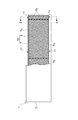
最初に、第1の実施形態に係る製造方法によって製造された軽量気泡コンクリート(以下、「ALC」という)パネル1について図1〜図3を参照して説明する。 First, a lightweight cellular concrete (hereinafter referred to as “ALC”) panel 1 manufactured by the manufacturing method according to the first embodiment will be described with reference to FIGS.
図1、及び図2に示されるように、ALCパネル1は、ALCによって矩形板状に形成されたパネル本体3と、パネル本体3内に埋設された補強筋構造5Aとを備えている。補強筋構造5Aは、一対の補強筋マット7と、一対の補強筋マット7同士の間で、補強筋マット7と離間した状態で配置された網状補強部材9とを備えている。
As shown in FIGS. 1 and 2, the ALC panel 1 includes a panel
補強筋マット7は、パネル本体3の長手方向に沿って延在する二本の平行な主筋7aと、主筋7aに対して交差(直交)し、パネル本体3の短手方向に沿って延在する五本の副筋7bとを備えている。一対の補強筋マット7は、パネル本体3のパネル面に沿って平行に配置されている。
The reinforcing
補強筋マット7の五本の副筋7bのうち、二本の副筋7bは、パネル本体3の長手方向の両端部近傍に配置することが望ましい。パネル本体3の長手方向の両端部それぞれに副筋7bを配置することにより、主筋7aがALCからなるパネル本体3に充分に定着し、またALCパネル1の端部に取り付けられるファスナーの取付強度を確保することができる。
Of the five
網状補強部材9は、メタルラスやワイヤラス等からなる平面状の網状部材であり、金網、ラス網、エキスパンドメタルなどが使用できる。例えば、金網に使用される鉄線の線径、及びラス網やエキスパンドメタルの板厚は、補強効果や孔あけ作業時の作業性を考慮して決めれば良く、0.6mm〜1.2mm程度が好ましい。また、網目の寸法は、網状補強部材9のパネル本体3(ALC母材)への付着性、または貫通孔や開口の間隔を考慮して決めれば良く、10mm〜60mm程度が好ましい。
The
また、網状補強部材9がラス網である場合には、3号、4号などの平ラス或いは1号、2号などの波形ラスを採用することができ、その際の網状補強部材9の長目方向の目(網目)の寸法は(菱形の長径)は26mm〜32mmであり、短目方向の目(網目)の寸法は(菱形の短径)は13mm〜16mmである。
When the
網状補強部材9は、一対の補強筋マット7同士に間に挟まれ、補強筋マット7それぞれとの間で一定の間隔Da,Db(図2参照)を空けた状態で、補強筋マット7に対向配置されている。
The net-like reinforcing
また、補強筋構造5Aは、補強筋マット7と網状補強部材9とを一定の間隔Da,Dbを空けて結合する取り付け部材11を備えており、さらに、補強筋構造5Aの上端には補強筋吊り下げ用スペーサー(図示省略)が固定されている。
The reinforcing
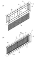
取り付け部材11(図2、及び図3参照)は、略π字状の部材(以下、「π型取り付け部材」という)11であり、網状補強部材9の網目9aに通されて網状補強部材9に当接する棒状の支え部11aと、支え部11aに立設され、且つ網状補強部材9の厚みに対応する隙間dを空けて配置された一対の棒状の挟み部11bと、を備えている。
The attachment member 11 (see FIG. 2 and FIG. 3) is a substantially π-shaped member (hereinafter referred to as “π-type attachment member”) 11, and is passed through the
π型取り付け部材11は、一対の挟み部11b同士の間において支え部11aが網状補強部材9に当接して網状補強部材9を支えており、一対の挟み部11bは、網状補強部材9を左右から挟むようにして網状補強部材9を保持している。また、支え部11aの両端は、一対の補強筋マット7の主筋7aに当接され、溶接されている。なお、本実施形態では、π型取り付け部材11の支え部11aが補強筋マット7の主筋7aに固定された態様を説明するが、副筋7bに固定してもよい。
The π-
次に、図3、及び図4を参照して第1実施形態に係るALCパネル1の製造方法について説明する。本実施形態では、八個のπ型取り付け部材11を用いており、また、π型取り付け部材11は、補強筋構造5Aの上方の四箇所、及び下方の四箇所に配置されている。なお、ALCパネル1の長手方向におけるπ型取り付け部材11の個数やレイアウトなどの頻度は、例えば、補強筋構造5Aの防錆処理時において、補強筋マット7と網状補強部材9との接触を防止できるものであれば任意に変更が可能であり、特に限定するものではない。また、ALCパネル1の短手方向におけるπ型取り付け部材11の個数やレイアウトなどの頻度も、例えば、補強筋構造5Aの防錆処理時において、補強筋マット7と網状補強部材9との接触を防止できるものであれば任意に変更が可能であり、特に限定するものではない。
Next, a method for manufacturing the ALC panel 1 according to the first embodiment will be described with reference to FIGS. 3 and 4. In the present embodiment, eight π-
本実施形態に係る製造方法は、補強筋構造形成工程、防錆工程、原料スラリーの発泡硬化工程、モルタルブロックの切断工程、養生工程を備えている。 The manufacturing method according to the present embodiment includes a reinforcing bar structure forming step, a rust prevention step, a foam hardening step of raw material slurry, a mortar block cutting step, and a curing step.
補強筋構造形成工程では、補強筋マット7と網状補強部材9とを対向配置すると共に、π型取り付け部材11を介して補強筋マット7と網状補強部材9とを離間させた状態で結合して補強筋構造5Aを形成する。
In the reinforcing bar structure forming step, the reinforcing
具体的には、π型取り付け部材11を網状補強部材9の網目9aに通し、一対の挟み部11bで網状補強部材9を挟む位置までπ型取り付け部材11を差し込む。次に、π型取り付け部材11を持ち上げて支え部11aを網状補強部材9に当接させ、支え部11aを網状補強部材9に引っ掛けるようにして網状補強部材9をπ型取り付け部材11で支持する。その結果、網状補強部材9は、π型取り付け部材11の定位置に保持された状態になる。
Specifically, the π-
次に、一対の補強筋マット7を、網状補強部材9を挟むように対向配置する。この状態で、補強筋マット7は、それぞれ網状補強部材9から離間し、且つ網状補強部材9に対向配置された状態になる。網状補強部材9の定位置には八個のπ型取り付け部材11が配置されている。π型取り付け部材11の支え部11aは、両端部分が補強筋マット7の主筋7aに当接され、主筋7aに溶接される。
Next, the pair of reinforcing
網状補強部材9は、π型取り付け部材11の挟み部11b、及び支え部11aによって定位置に保持されており、π型取り付け部材11を介して網状補強部材9を左右一対の補強筋マット7に固定することで、網状補強部材9が一対の補強筋マット7から離間して結合された補強筋構造5Aが完成する。
The
次に、補強筋構造5Aの防錆処理を行う防錆工程が実行される。防錆工程では、防錆液が満たされた浸漬槽に補強筋構造5Aを完全に漬けて補強筋構造5Aの表面に防錆液を付着させる。ここで、補強筋マット7と網状補強部材9とは離間して配置されているので、補強筋マット7と網状補強部材9との略全面に渡って防錆液が付着した状態になる。防錆液を付着させた後、補強筋構造5Aを乾燥させて防錆塗膜を形成する。
Next, the rust prevention process which performs the rust prevention process of 5 A of reinforcement reinforcement structures is performed. In the rust prevention step, the reinforcing
次に、原料スラリーの発泡硬化工程を実行する。防錆塗膜が形成された補強筋マット7は型枠中に配置される。この型枠内に、石灰質原料及び珪酸質原料を粉砕したもの、適量の水、及び気泡剤等を混合した原料スラリーを注入し、補強筋構造5Aをパネル状に包囲し、発泡硬化させてモルタルブロックを形成する。
Next, a foam curing step of the raw material slurry is performed. The reinforcing
発泡硬化したモルタルブロックの形成後、モルタルブロックをピアノ線等により所望の寸法に切断し(モルタルブロックの切断工程)、オートクレープ養生を施して(養生工程)、所定形状のALCパネル1が完成する。 After the foam-cured mortar block is formed, the mortar block is cut into a desired dimension with a piano wire or the like (a mortar block cutting step) and subjected to autoclave curing (curing step) to complete the ALC panel 1 having a predetermined shape. .
次に、本実施形態に係る製造方法の作用、及び効果について説明する。この製造方法では、前提として、補強筋マット7と網状補強部材9とが離間しているため、防錆処理を施した際に補強筋構造5Aの略全面に渡って防錆塗膜が形成される。従って、原料スラリーの発泡硬化の際に補強筋構造5Aに応力がかかり、例えば、補強筋マット7と網状補強部材9との離間幅が変化したとしても防錆塗膜の欠損とはならない。従って、本実施形態に係る製造方法によれば、補強筋構造5Aの防錆塗膜の欠損を効果的に防止でき、高品質のALCパネル1の製造が可能になる。
Next, the operation and effect of the manufacturing method according to this embodiment will be described. In this manufacturing method, as a premise, since the reinforcing
特に、本実施形態に係る製造方法によれば、例えば、補強筋マットと網状補強部材との略全面を溶接などによって固定して防錆塗膜の欠損防止を図る態様に比べて、防錆処理に係わる懸念を完全に解決でき、また、同時に製造工数の増大を抑制し、さらに、製造コストの増大をも抑止できる。 In particular, according to the manufacturing method according to the present embodiment, for example, compared with an aspect in which the entire surface of the reinforcing bar mat and the net-like reinforcing member is fixed by welding or the like to prevent the rust-preventing coating from being damaged, In addition, it is possible to completely solve the concerns related to the above, and at the same time, it is possible to suppress an increase in manufacturing man-hours and to suppress an increase in manufacturing cost.
なお、以上の実施形態では、π型取り付け部材11と補強筋マット7との結合は溶接によって行っているが、十分な固定強度が得られれば溶接のみに限定されるものではなく、接着などであってもよい。またπ型取り付け部材11と補強筋マット7の固定は、補強筋マット7の主筋7a、または副筋7bのどちらに対しても実施可能ではあるが、防錆処理時において、補強筋マット7と網状補強部材9との接触を防ぎ得る頻度を確保するためには、主筋7aに固定する方が望ましい。
In the above embodiment, the coupling between the π-
また、本実施形態では、網状補強部材9はπ型取り付け部材11に引っ掛かっているだけで、特に溶接等されていないが、溶接などによって強固に固定するようにしても良い。
Further, in the present embodiment, the
また、π型取り付け部材11の挟み部11bの長さは、網状補強部材9の網目9aに通すことが可能であり、また、網状補強部材9を十分に挟み込むことができれば、特に限定するものではない。また、π型取り付け部材11の支え部11aに対する挟み部11bの位置も、ALCパネル1の厚み方向における網状補強部材9の位置に応じて任意に変更可能である。
Further, the length of the sandwiching
また、π型取り付け部材11による補強筋マット7と網状補強部材9との結合位置のうち、上方に存在する結合位置では、π型取り付け部材11の挟み部11bを上方に向けて施工し、下方に存在する結合位置では、π型取り付け部材11の挟み部11bを下方に向けて施工することにより、振動等により網状補強部材9の固定が外れる不具合を防止できるため、より好ましい。
Further, among the coupling positions of the reinforcing
また、本実施形態では、補強筋マット7の略全面に重なる網状補強部材9を用意し、この網状補強部材9を補強筋マット7に固定しているが、この形態に限定されるものではなく、網状補強部材9を固定する部分は、補強筋マット7の必要とされる一部分だけでも良い。また、各補強筋マット7の主筋7aはALCパネル1の長手方向に平行に2本以上配設してもよく、また、副筋7bはALCパネル1の短手方向に平行に3本以上配設してもよい。
(第2の実施形態)
Further, in this embodiment, a net-like reinforcing
(Second Embodiment)
次に、本発明の第2実施形態に係る製造方法について、図5を参照して説明する。なお、本実施形態に係る製造方法にて製造されるALCパネル1は、第1実施形態に係る製造方法によって製造されるALCパネル1と実質的に同一の構造や要素を備えている。従って、同一の構造や要素については、第1実施形態に係るALCパネル1と同一の符号を付して詳細な説明は省略する。また、製造方法の各工程についても、第1実施形態に係る製造方法と同一の工程を備えているため、同一の工程については詳細な説明を省略する。 Next, a manufacturing method according to the second embodiment of the present invention will be described with reference to FIG. The ALC panel 1 manufactured by the manufacturing method according to the present embodiment has substantially the same structure and elements as the ALC panel 1 manufactured by the manufacturing method according to the first embodiment. Accordingly, the same structures and elements are denoted by the same reference numerals as those of the ALC panel 1 according to the first embodiment, and detailed description thereof is omitted. Moreover, since each process of the manufacturing method includes the same process as the manufacturing method according to the first embodiment, detailed description of the same process is omitted.
本実施形態に係る製造方法では、第1実施形態に係る製造方法に比較して補強筋マット7と網状補強部材9とを結合するために用いる取り付け部材21が異なる。
The manufacturing method according to the present embodiment differs from the manufacturing method according to the first embodiment in the
取り付け部材21は、略V字状の部材(以下、「V型取り付け部材」という)21であり、V字状に屈曲した係止部21aと係止部21aの両端から突き出すと共に、係止部21aを挟んで同一軸線L上に対向配置された一対の腕部21bと、を有する。
The
V型取り付け部材21は、係止部21aが網状補強部材9を挟むように当接して網状補強部材9を支え、定位置に保持している。また、腕部21bの両端は、一対の補強筋マット7の主筋7aに当接され、溶接されている。なお、本実施形態では、V型取り付け部材21の係止部21aが補強筋マット7の主筋7aに固定された態様を説明するが、副筋7bに固定してもよい。
The V-shaped
本実施形態に係る製造方法では、八個のV型取り付け部材21を用いており、また、取り付け部材21は、補強筋構造5Bの上方の四箇所、及び下方の四箇所に配置されている。なお、ALCパネル1の長手方向におけるV型取り付け部材21の個数やレイアウトなどの頻度は、例えば、補強筋構造5Bの防錆処理時において、補強筋マット7と網状補強部材9との接触を防止できるものであれば任意に変更が可能であり、特に限定するものではない。また、ALCパネル1の短手方向におけるV型取り付け部材21の個数やレイアウトなどの頻度も、例えば、補強筋構造5Bの防錆処理時において、補強筋マット7と網状補強部材9との接触を防止できるものであれば任意に変更が可能であり、特に限定するものではない。
In the manufacturing method according to the present embodiment, eight V-shaped
本実施形態に係る製造方法は、補強筋構造形成工程、防錆工程、原料スラリーの発泡硬化工程、モルタルブロックの切断工程、養生工程を備えている。防錆工程、原料スラリーの発泡硬化工程、モルタルブロックの切断工程、及び養生工程については、第1の実施形態に係る製造方法と同様であるため、詳しい説明は省略する。 The manufacturing method according to the present embodiment includes a reinforcing bar structure forming step, a rust prevention step, a foam hardening step of raw material slurry, a mortar block cutting step, and a curing step. Since the antirust process, the foam hardening process of the raw material slurry, the cutting process of the mortar block, and the curing process are the same as those in the manufacturing method according to the first embodiment, detailed description thereof is omitted.
補強筋構造形成工程では、V型取り付け部材21を網状補強部材9の網目9aに通し、係止部21aで網状補強部材9を支持する位置までV型取り付け部材21を差し込む。次に、V型取り付け部材21を持ち上げて係止部21aを網状補強部材9に当接させ、係止部21aを網状補強部材9に引っ掛けるようにして網状補強部材9をV型取り付け部材21で支持する。その結果、網状補強部材9は、V型取り付け部材21の定位置に保持された状態になる。
In the reinforcing bar structure forming step, the V-shaped
次に、一対の補強筋マット7を、網状補強部材9を挟むように対向配置する。この状態で、補強筋マット7は、それぞれ網状補強部材9から離間し、且つ網状補強部材9に対向配置された状態になる。網状補強部材9の定位置には八個のV型取り付け部材21が配置されている。V型取り付け部材21の腕部21bは、両端部分が補強筋マット7の主筋7aに当接するように載せられ、腕部21bと主筋7aとは溶接などで固定される。
Next, the pair of reinforcing
網状補強部材9は、V型取り付け部材21の係止部21aによって定位置に保持されており、V型取り付け部材21を介して網状補強部材9を左右一対の補強筋マット7に固定することで、網状補強部材9が一対の補強筋マット7から離間して結合された補強筋構造5Bが完成する。
The
本実施形態に係る製造方法では、前提として、補強筋マット7と網状補強部材9とが離間しているため、防錆処理を施した際に補強筋構造5Bの略全面に渡って防錆塗膜が形成される。従って、原料スラリーの発泡硬化の際に補強筋構造5Bに応力がかかり、例えば、補強筋マット7と網状補強部材9との離間幅が変化したとしても防錆塗膜の欠損とはならない。従って、本実施形態に係る製造方法によれば、補強筋構造5Bの防錆塗膜の欠損を効果的に防止でき、高品質のALCパネル1の製造が可能になる。
In the manufacturing method according to the present embodiment, as a premise, since the reinforcing
特に、本実施形態に係る製造方法によれば、例えば、補強筋マットと網状補強部材との略全面を溶接などによって固定して防錆塗膜の欠損防止を図る態様に比べて、防錆処理に係わる懸念を完全に解決でき、また、同時に製造工数の増大を抑制し、さらに、製造コストの増大をも抑制できる。 In particular, according to the manufacturing method according to the present embodiment, for example, compared with an aspect in which the entire surface of the reinforcing bar mat and the net-like reinforcing member is fixed by welding or the like to prevent the rust-preventing coating from being damaged, Concerns about the problem can be solved completely, and at the same time, an increase in the number of manufacturing steps can be suppressed, and an increase in manufacturing cost can also be suppressed.
なお、以上の実施形態では、V型取り付け部材21と補強筋マット7との結合は溶接にて行っているが、十分な固定強度が得られれば溶接のみに限定されるものではなく、接着などであってもよい。またV型取り付け部材21と補強筋マット7の固定は、補強筋マット7の主筋7a、または副筋7bのどちらに対しても実施可能ではあるが、防錆処理時において、補強筋マット7と網状補強部材9との接触を防ぎ得る頻度を確保するためには、主筋7aに固定する方が望ましい。
In the above embodiment, the V-shaped
また、本実施形態では、網状補強部材9はV型取り付け部材21に引っ掛かっているだけで、特に溶接等されていないが、溶接などによって強固に固定するようにしても良い。
In this embodiment, the
また、V型取り付け部材21の係止部21aの長さは、網状補強部材9の網目9aを通すことが可能であり、また、網状補強部材9を十分に挟み込むことができれば、特に限定するものではない。また、V型取り付け部材21の係止部21aの位置も、ALCパネル1の厚み方向における網状補強部材9の位置に応じて任意に変更可能である。
Further, the length of the locking
また、V型取り付け部材21による補強筋マット7と網状補強部材9との結合位置のうち、上方に存在する結合位置では、V型取り付け部材21の係止部21aを下方に向けて施工し、下方に存在する結合位置では、V型取り付け部材21の係止部21aを上方に向けて施工することにより、振動等により網状補強部材9の固定が外れる不具合を防止できるため、より好ましい。
Further, among the coupling positions of the reinforcing
1…ALCパネル(軽量気泡コンクリートパネル)、5A,5B…補強筋構造、7…補強筋マット、9…網状補強部材、9a…網目、11…π型取り付け部材、11a…支え部、11b…挟み部、21…V型取り付け部材、21a…係止部、21b…腕部、L…軸線。
DESCRIPTION OF SYMBOLS 1 ... ALC panel (lightweight cellular concrete panel), 5A, 5B ... Reinforcement structure, 7 ... Reinforcement reinforcement mat, 9 ... Reticulated reinforcement member, 9a ... Mesh, 11 ... Pi-type attachment member, 11a ... Supporting part, 11b ...
Claims (4)
前記補強筋マットと網状補強部材とを対向配置すると共に、取り付け部材を介して前記補強筋マットと前記網状補強部材とを離間させた状態で結合することによって前記補強筋構造を形成する補強筋構造形成工程を備えることを特徴とする軽量気泡コンクリートパネルの製造方法。 A method of manufacturing a lightweight aerated concrete panel manufactured by surrounding a reinforcing bar structure including a reinforcing bar mat in a panel shape with a raw material slurry, and foaming and curing the raw material slurry,
A reinforcing bar structure that forms the reinforcing bar structure by disposing the reinforcing bar mat and the net-like reinforcing member opposite to each other and connecting the reinforcing bar mat and the net-like reinforcing member in a separated state via an attachment member. A method for producing a lightweight cellular concrete panel, comprising a forming step.
前記補強筋構造形成工程では、
前記取り付け部材を前記網状補強部材の網目に通し、一対の前記挟み部で前記網状補強部材を挟みながら前記支え部を前記網状補強部材に当接させて前記網状補強部材を支持すると共に、前記支え部を前記補強筋マットに固定することにより、前記補強筋マットと前記網状補強部材とを離間させた状態で結合することを特徴とする請求項1または2記載の軽量気泡コンクリートパネルの製造方法。 The mounting member is disposed through a mesh of the mesh reinforcing member and abuts against the mesh reinforcing member, and is installed on the support portion with a gap corresponding to the thickness of the mesh reinforcing member. A pair of clip portions,
In the reinforcing bar structure forming step,
The attachment member is passed through the mesh of the mesh reinforcing member, and the support member is supported against the mesh reinforcing member by sandwiching the mesh reinforcing member between the pair of the sandwiching portions to support the mesh reinforcing member. 3. The method of manufacturing a lightweight cellular concrete panel according to claim 1, wherein the reinforcing bar mat and the mesh reinforcing member are joined apart from each other by fixing a portion to the reinforcing bar mat.
前記補強筋構造形成工程では、
前記取り付け部材を前記網状補強部材の網目に通し、前記係止部で前記網状補強部材を支持すると共に、前記腕部を前記補強筋マットに固定することにより、前記補強筋マットと前記網状補強部材とを離間させた状態で結合することを特徴とする請求項1または2記載の軽量気泡コンクリートパネルの製造方法。 The mounting member includes a locking portion bent in a V shape, and a pair of arm portions protruding from both ends of the locking portion and facing each other on the same axis across the locking portion. ,
In the reinforcing bar structure forming step,
By passing the attachment member through the mesh of the mesh reinforcing member, and supporting the mesh reinforcing member by the locking portion, and fixing the arm portion to the reinforcement reinforcing mat, the reinforcement reinforcing mat and the mesh reinforcing member 3. The method for producing a lightweight cellular concrete panel according to claim 1, wherein the two are connected in a separated state.
Priority Applications (1)
| Application Number | Priority Date | Filing Date | Title |
|---|---|---|---|
| JP2010290745A JP5705533B2 (en) | 2010-12-27 | 2010-12-27 | Method for producing lightweight cellular concrete panel |
Applications Claiming Priority (1)
| Application Number | Priority Date | Filing Date | Title |
|---|---|---|---|
| JP2010290745A JP5705533B2 (en) | 2010-12-27 | 2010-12-27 | Method for producing lightweight cellular concrete panel |
Publications (2)
| Publication Number | Publication Date |
|---|---|
| JP2012136885A true JP2012136885A (en) | 2012-07-19 |
| JP5705533B2 JP5705533B2 (en) | 2015-04-22 |
Family
ID=46674501
Family Applications (1)
| Application Number | Title | Priority Date | Filing Date |
|---|---|---|---|
| JP2010290745A Expired - Fee Related JP5705533B2 (en) | 2010-12-27 | 2010-12-27 | Method for producing lightweight cellular concrete panel |
Country Status (1)
| Country | Link |
|---|---|
| JP (1) | JP5705533B2 (en) |
Cited By (2)
| Publication number | Priority date | Publication date | Assignee | Title |
|---|---|---|---|---|
| CN105952059A (en) * | 2016-07-05 | 2016-09-21 | 北京交通大学 | Reinforcing bar anchorage method used instead of strong-strength reinforcing bar hooking |
| CN113931341A (en) * | 2021-10-12 | 2022-01-14 | 连云港中砼新型建筑科技有限公司 | Prevent autoclaved aerated concrete wallboard that ftractures and drop |
Citations (5)
| Publication number | Priority date | Publication date | Assignee | Title |
|---|---|---|---|---|
| JPS56105005U (en) * | 1980-01-11 | 1981-08-17 | ||
| JPS63112541U (en) * | 1987-01-16 | 1988-07-20 | ||
| JPH05305610A (en) * | 1992-05-01 | 1993-11-19 | Asahi Chem Ind Co Ltd | Rustproof coating treatment method of iron reinforcing rod for lightweight foam concrete |
| JPH0716826U (en) * | 1993-09-06 | 1995-03-20 | 株式会社ナルックス | Welded wire mesh spacer for concrete reinforcement |
| JP2010077624A (en) * | 2008-09-25 | 2010-04-08 | Asahi Kasei Construction Materials Co Ltd | Autoclaved lightweight concrete panel |
-
2010
- 2010-12-27 JP JP2010290745A patent/JP5705533B2/en not_active Expired - Fee Related
Patent Citations (5)
| Publication number | Priority date | Publication date | Assignee | Title |
|---|---|---|---|---|
| JPS56105005U (en) * | 1980-01-11 | 1981-08-17 | ||
| JPS63112541U (en) * | 1987-01-16 | 1988-07-20 | ||
| JPH05305610A (en) * | 1992-05-01 | 1993-11-19 | Asahi Chem Ind Co Ltd | Rustproof coating treatment method of iron reinforcing rod for lightweight foam concrete |
| JPH0716826U (en) * | 1993-09-06 | 1995-03-20 | 株式会社ナルックス | Welded wire mesh spacer for concrete reinforcement |
| JP2010077624A (en) * | 2008-09-25 | 2010-04-08 | Asahi Kasei Construction Materials Co Ltd | Autoclaved lightweight concrete panel |
Cited By (2)
| Publication number | Priority date | Publication date | Assignee | Title |
|---|---|---|---|---|
| CN105952059A (en) * | 2016-07-05 | 2016-09-21 | 北京交通大学 | Reinforcing bar anchorage method used instead of strong-strength reinforcing bar hooking |
| CN113931341A (en) * | 2021-10-12 | 2022-01-14 | 连云港中砼新型建筑科技有限公司 | Prevent autoclaved aerated concrete wallboard that ftractures and drop |
Also Published As
| Publication number | Publication date |
|---|---|
| JP5705533B2 (en) | 2015-04-22 |
Similar Documents
| Publication | Publication Date | Title |
|---|---|---|
| US7757454B2 (en) | Composite building panel and method of making composite building panel | |
| JP5705533B2 (en) | Method for producing lightweight cellular concrete panel | |
| JP2001003506A (en) | Construction method for void slab and embedded member for void formation | |
| KR100979264B1 (en) | mold of form panel comprising paper corrugated cardboard | |
| JP2007162252A (en) | Heat insulating construction method for exterior wall and roof of steel-frame building | |
| JP5620259B2 (en) | Method for producing lightweight cellular concrete panel | |
| CN110714532A (en) | Assembly structure and installation method of wallboard and steel beam | |
| JP5281919B2 (en) | Outside heat insulation foundation structure and its construction method | |
| CN205063134U (en) | Case is filled to combination formula metal of band stop lodicule | |
| US20080148675A1 (en) | Composite masonry block | |
| JP2005188194A (en) | Knockdown form unit | |
| JP2010240905A (en) | Method for manufacturing ribbed cement panel, ribbed cement panel, and method for manufacturing structure | |
| KR0178690B1 (en) | Deck girder adn panel for reinforced concrete slab | |
| KR200234547Y1 (en) | Deck panel of reinforced concrete slab | |
| JP4815157B2 (en) | Sandwich panel and its manufacturing method | |
| KR200296951Y1 (en) | Deck panel for reinforced concrete slab | |
| KR200340346Y1 (en) | Truss deck panel for slab | |
| JP2000104392A (en) | Floor panel and its manufacture | |
| KR101164585B1 (en) | A Hybrid Unit Panel for Exterior Wall | |
| KR200368256Y1 (en) | Deck plate for flat slab/flat plate slab and deck plate connection structure | |
| JP3679381B2 (en) | Thermal insulation composite panel | |
| JP4004055B2 (en) | Manufacturing method of outer heat insulation precast concrete body | |
| JP2018084034A (en) | Reinforcing structure for concrete structure and reinforcing method | |
| JP2009126175A (en) | Method for manufacturing three-dimensional fiber-reinforced structure with long fibers | |
| JP2604938Y2 (en) | Thermal insulation panel |
Legal Events
| Date | Code | Title | Description |
|---|---|---|---|
| A621 | Written request for application examination |
Free format text: JAPANESE INTERMEDIATE CODE: A621 Effective date: 20131219 |
|
| A977 | Report on retrieval |
Free format text: JAPANESE INTERMEDIATE CODE: A971007 Effective date: 20140825 |
|
| A131 | Notification of reasons for refusal |
Free format text: JAPANESE INTERMEDIATE CODE: A131 Effective date: 20140902 |
|
| A521 | Written amendment |
Free format text: JAPANESE INTERMEDIATE CODE: A523 Effective date: 20141029 |
|
| TRDD | Decision of grant or rejection written | ||
| A01 | Written decision to grant a patent or to grant a registration (utility model) |
Free format text: JAPANESE INTERMEDIATE CODE: A01 Effective date: 20150224 |
|
| A61 | First payment of annual fees (during grant procedure) |
Free format text: JAPANESE INTERMEDIATE CODE: A61 Effective date: 20150225 |
|
| R150 | Certificate of patent or registration of utility model |
Ref document number: 5705533 Country of ref document: JP Free format text: JAPANESE INTERMEDIATE CODE: R150 |
|
| LAPS | Cancellation because of no payment of annual fees |