JP2012135737A - Static mixing mechanism - Google Patents
Static mixing mechanism Download PDFInfo
- Publication number
- JP2012135737A JP2012135737A JP2010290768A JP2010290768A JP2012135737A JP 2012135737 A JP2012135737 A JP 2012135737A JP 2010290768 A JP2010290768 A JP 2010290768A JP 2010290768 A JP2010290768 A JP 2010290768A JP 2012135737 A JP2012135737 A JP 2012135737A
- Authority
- JP
- Japan
- Prior art keywords
- mixing mechanism
- pipe
- hub
- flow
- air
- Prior art date
- Legal status (The legal status is an assumption and is not a legal conclusion. Google has not performed a legal analysis and makes no representation as to the accuracy of the status listed.)
- Pending
Links
- 230000007246 mechanism Effects 0.000 title claims abstract description 45
- 230000003068 static effect Effects 0.000 title claims abstract description 29
- 239000012530 fluid Substances 0.000 claims abstract description 28
- 238000011144 upstream manufacturing Methods 0.000 claims description 26
- 230000007423 decrease Effects 0.000 claims description 7
- 238000003756 stirring Methods 0.000 abstract description 8
- 238000009434 installation Methods 0.000 abstract description 4
- 230000000694 effects Effects 0.000 description 4
- 238000004378 air conditioning Methods 0.000 description 2
- 239000003814 drug Substances 0.000 description 2
- 238000000605 extraction Methods 0.000 description 2
- 230000003247 decreasing effect Effects 0.000 description 1
- 238000010790 dilution Methods 0.000 description 1
- 239000012895 dilution Substances 0.000 description 1
- 229940079593 drug Drugs 0.000 description 1
- 239000007788 liquid Substances 0.000 description 1
- 238000004519 manufacturing process Methods 0.000 description 1
- 239000002699 waste material Substances 0.000 description 1
- XLYOFNOQVPJJNP-UHFFFAOYSA-N water Substances O XLYOFNOQVPJJNP-UHFFFAOYSA-N 0.000 description 1
Images


Abstract
Description
流体を流通させるための配管中に配設してなる静止型ミキシング機構に関する。 The present invention relates to a static mixing mechanism provided in a pipe for circulating a fluid.
従来より、流体を流通させるための配管中に配設してなる静止型ミキシング機構として、種々の構成のものが考えられてきている。 2. Description of the Related Art Conventionally, various types of stationary mixing mechanisms have been considered as a stationary mixing mechanism disposed in a pipe for circulating a fluid.
その一例として、航空機の空調装置に用いられ、ミキシングチャンバ(混合室)を備えたものが挙げられる(例えば、特許文献1を参照)。このような静止型ミキシング機構のミキシングチャンバは、箱形をなし、その内部の空間で第1の流体、例えば高温の空気と第2の流体、例えば低温の空気とを均一に混合させるためのチャンバ本体と、このチャンバ本体内に第1の流体を導入するための第1の導入口と、前記チャンバ本体内に第2の流体を導入するための第2の導入口と、前記チャンバ本体内で混合された流体を外部に導出させるための導出口とを有する。なお、3種類以上の流体を均一に混合させるためのミキシングチャンバも、導入口の数が混合させるべき流体の種類に対応して増加する以外は同様の構成を有する。 As an example, there is one that is used in an air conditioner for an aircraft and includes a mixing chamber (mixing chamber) (for example, see Patent Document 1). The mixing chamber of such a static mixing mechanism has a box shape and is a chamber for uniformly mixing a first fluid, for example, hot air and a second fluid, for example, cold air, in the space inside the box. A main body, a first inlet for introducing a first fluid into the chamber body, a second inlet for introducing a second fluid into the chamber body, and the chamber body. And an outlet for leading the mixed fluid to the outside. The mixing chamber for uniformly mixing three or more types of fluids has the same configuration except that the number of inlets increases corresponding to the type of fluid to be mixed.
ところで、前記特許文献1記載のもののようなミキシングチャンバを備えた静止型ミキシング機構においては、配管系の中途に前記チャンバ本体を設ける必要があるが、このようなチャンバ本体は、その内部で複数の流体を十分均一に混合させる必要から、内部空間を大きくとる必要がある。また、高温の抽気と低温のラムエアとを熱交換させるための熱交換器を通過した配管中の空気や、エアサイクルシステム中に設けられ内部にバイパス通路を有する熱交換器を通過した配管中の空気は、配管内の部位により温度分布にムラがあるが、このような配管中の空気の温度分布を均一にするために内部に大きな空間を有するチャンバを配設することは、スペースの無駄となる場合がある。
By the way, in a static type mixing mechanism having a mixing chamber such as that described in
そこで、状態の異なる流体が同時に内部を通過可能な配管内部に配設可能な静止型ミキシング機構が種々考えられている。 Therefore, various types of static mixing mechanisms have been conceived in which fluids in different states can be arranged inside the pipe that can pass through the inside at the same time.
しかし、前記特許文献2記載のもの構成は、気体の流れを衝突筒体に衝突させて逆流させることにより攪拌していることから、配管中の流体の流れと逆流した気体との衝突により流体の流れに大きな乱れが発生し、従って圧力損失が大きくなる。
However, since the configuration described in
また、前記特許文献3記載の構成は、配管中にその法線が流路方向に対して角度を有するとともに孔を多数設けたベーンを配設するものであるが、流体がベーンの上流側端縁に達すると流体の流れの方向が静止型混合器の上流側端縁において大きく変化し、また、孔を通過する流体の流れとベーンの面に沿う流体の流れとが互いに影響しあって流体の流れに乱れが発生し、圧力損失が大きくなる。
In the configuration described in
さらに、前記非特許文献1記載の構成は、配管中にひねり羽根を90°ずつ位相を変化させつつ複数配するものであるが、十分なミキシング効果を得るにはひねり羽根を少なくとも4〜6個直列に配置する必要があり、ひねり羽根の長さは半径の1.4〜2倍であるので、静止型ミキシング機構全体としては半径の6倍以上の長さを有し、圧力損失が大きくなる。
Further, the configuration described in
そして、このような課題は、航空機の空調装置に用いられるものに限らず、状態の異なる流体を攪拌するための静止型ミキシング機構には一般に存在する。 Such problems are not limited to those used in air conditioners for aircraft, but generally exist in stationary mixing mechanisms for stirring fluids in different states.
本発明は以上の点に着目し、限られた設置スペースにおいて十分な攪拌性能を実現しつつ、圧力損失が小さく流路方向長さ寸法が短い静止型混合器を備えたミキシング機構を実現することを目的とする。 The present invention pays attention to the above points, and realizes a mixing mechanism having a static mixer with a small pressure loss and a short length in the flow direction direction while realizing sufficient stirring performance in a limited installation space. With the goal.
すなわち本発明に係る静止型ミキシング機構は、配管中に配設してなる静止型ミキシング機構であって、配管の中心部分に配されるハブと、このハブから径方向に突出して複数設けられそれぞれが下流側に向かうにつれて位相が変化するとともに配管に対して回転不能であるベーンとを有し、状態又は成分が異なる流体が同時に流通している場合に前記ベーン間の空間を通過することにより螺旋状の旋回流となることを特徴とする。 That is, the stationary mixing mechanism according to the present invention is a stationary mixing mechanism disposed in a pipe, and includes a hub disposed in a central portion of the pipe and a plurality of protrusions projecting radially from the hub. And a vane whose phase changes as it goes downstream and which cannot rotate with respect to the piping, and when fluids having different states or components are circulating simultaneously, the spiral passes through the space between the vanes. It is characterized by a swirling flow.
このようなものであれば、ベーン間を通過した空気の流れが旋回流となり、気体の流れが流路方向に単位距離進んだ場合の実質的な流路長さを長くすることができる。また、ベーン間を通過した空気の流れが旋回流となることから、流体の大半が配管の管壁近傍を流通するので、実質的な流路面積が小さくなり、前述したように実質的な流路長さが長くなることと併せて、実質的な流速を高くできる。すなわち、実質的な流路長さを長くしさらに実質的な流速を高くすることにより、単位長さ当たりのミキシング効果を高めることができる。従って、配管内部にこの静止型ミキシング機構を配することにより設置スペースの削減を図り、さらにこの静止型ミキシング機構の流路方向の長さを小さくできるとともに、圧力損失を小さくして空調効率を向上させることができる。 If it is such, the flow of the air which passed between vanes turns into a swirl flow, and the substantial flow path length when a gas flow advances unit distance in the flow path direction can be lengthened. In addition, since the air flow that has passed between the vanes becomes a swirl flow, most of the fluid circulates in the vicinity of the pipe wall of the pipe. Along with the increase in the path length, the substantial flow velocity can be increased. That is, the mixing effect per unit length can be enhanced by increasing the substantial flow path length and further increasing the substantial flow velocity. Therefore, by installing this static mixing mechanism inside the piping, the installation space can be reduced, and the length of the static mixing mechanism in the flow path direction can be reduced, and the pressure loss is reduced to improve the air conditioning efficiency. Can be made.
なお、本発明において、「状態又は成分が異なる流体が同時に流通」とは、温度、濃度、密度等の物理量のうち少なくとも1つが異なる複数種類の流体が同一配管内を同時に流通している状態全般を示す概念である。 In the present invention, “fluids having different states or components flow at the same time” means a general state in which plural types of fluids having different physical quantities such as temperature, concentration, density, etc. are simultaneously flowing in the same pipe. It is the concept which shows.
特に、前記ベーンの上流側端部が、流路方向に平行に延伸している導入部であるものであれば、空気をベーン間の空間に円滑に導入することができるので、圧力損失を低下させることができる。 In particular, if the upstream end portion of the vane is an introduction portion that extends in parallel with the flow path direction, air can be smoothly introduced into the space between the vanes, thereby reducing pressure loss. Can be made.
また、前記ハブの上流側端縁を上流側に向かうにつれ径が小さくなる形状に形成しているものであれば、ハブの上流側端縁付近を通過する空気がベーン間の空間に円滑に導入されるので、この点からも圧力損失を低下させることができる。 Further, if the upstream edge of the hub is formed in a shape whose diameter decreases as it goes upstream, the air passing near the upstream edge of the hub is smoothly introduced into the space between the vanes. Therefore, the pressure loss can be reduced also from this point.
そして、前記ハブの下流側端縁を下流側に向かうにつれ径が小さくなる形状に形成しているものであれば、ハブの下流側端縁近傍に渦を発生させて効果的に空気を攪拌するようにしつつ、空気の流れの乱れを少なくして圧力損失の低下を抑えることができる。 If the downstream end edge of the hub is formed to have a shape that decreases in diameter toward the downstream side, air is effectively stirred by generating a vortex in the vicinity of the downstream end edge of the hub. In this way, it is possible to reduce the turbulence of the air flow and suppress the decrease in pressure loss.
本発明の静止型ミキシング機構の構成によれば、限られた設置スペースにおいて十分な攪拌性能を実現しつつ、静止型混合器による圧力損失を小さく、また静止型混合器の流路方向の長さ寸法を短くできる。 According to the configuration of the static mixing mechanism of the present invention, the pressure loss due to the static mixer is reduced while achieving sufficient stirring performance in a limited installation space, and the length of the static mixer in the flow path direction is reduced. Dimensions can be shortened.
以下、本発明の一実施形態を、図面を参照して説明する。 Hereinafter, an embodiment of the present invention will be described with reference to the drawings.
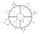
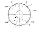
本実施形態に係る静止型ミキシング機構1は、航空機に用いられ、流体たる空気を内部に流通させてなる空調装置の配管2中に配設してなり、配管2の中心部分に配されるハブ3と、このハブ3から径方向に突出して複数、具体的には4枚設けられそれぞれが下流側に向かうにつれて位相が変化するとともに配管2に対して回転不能なベーン4とを有する。また、この静止型ミキシング機構1の流路方向の長さは、配管2の半径の約1.5倍である。なお、より具体的な配設箇所として、例えば、抽気とラムエアとの熱交換を行うための熱交換器の下流や、空調装置のエアサイクルマシンを構成するタービンの下流に設けられバイパス通路を内部に有する熱交換器の下流等が考えられる。
A
前記ハブ3は、流路方向に延伸する概略円柱状の部材であり、流路方向に直交する平面で切断した場合の断面形状が流路方向寸法の全域にわたって円形かつ同一形状であるハブ本体31と、このハブ本体31の上流側端縁に一体に設けられ、前記ハブ本体31とその表面が滑らかに連続する回転楕円体状をなす上流側ガイド部32と、前記ハブ本体31の下流側端縁に一体に設けられ、前記ハブ本体31とその表面が滑らかに連続する回転楕円体状をなす下流側ガイド部33とを備えている。
The
一方、前記ベーン4は、前記ハブ本体31から外方に突出する板状の部材で、本実施形態では互いに周方向に90°ずつ離間している。このベーン4は、上流側に位置し流路方向に平行に延伸している導入部41と、この導入部41に隣接して設けてなり下流側に向かうにつれて位相が変化する旋回流生成部42とをそれぞれ有する。前記旋回流生成部42は、図3に示すように、下流側に向かうにつれ単位長さ当たりの位相の変化率を大きく形成している。そして、互いに隣接するベーン4の旋回流生成部42間の空間Sを空気が通過することにより旋回流が生成される。
On the other hand, the
この静止型ミキシング機構1内を空気が通過する際の空気の流れを以下に述べる。
The flow of air when air passes through the
まず、空気の流れが静止型ミキシング機構1の上流側端縁に達すると、配管2の中心部を流通する空気は上流側ガイド部32に衝突し、上流側ガイド部32の表面にガイドされて静止型ミキシング機構1のベーン4間の空間Sに達する。一方、その他の部位を流通する空気の大部分はそのまま流路方向に進み静止型ミキシング機構1のベーン4間の空間Sに達する。そして、残りの空気は、前記ベーン4の上流側端縁に衝突してベーン4の表面にガイドされ、ベーン4間の前記空間Sに達する。前記空間Sに達した空気の流れは、まずベーン4の導入部41間の部位をそのまま直進し、次いで、ベーン4の旋回流生成部42間の部位に達する。前記旋回流生成部42間の部位に達した空気の流れはそのまま旋回流生成部42間の部位を通過することにより螺旋状の旋回流となる。ベーン4の下流側端縁を通過した空気の流れの大部分は螺旋状の旋回流としてそのまま配管2中を流通する。また、下流側ガイド部33の下流側に隣接する部位では、渦が発生する。そして、静止型ミキシング機構1を通過した空気は、螺旋状の旋回流として配管2中を流通することにより、また、その下流側に生成した渦と衝突することにより攪拌される。より具体的には、この静止型ミキシング機構1の下流側端縁から配管2の半径の1.5倍だけ離間した位置において、配管2内を流通する空気の温度は略一様となる。
First, when the air flow reaches the upstream edge of the
以上に述べたように、本実施形態に係る静止型ミキシング機構1の構成によれば、ベーン4間の空間Sを通過した空気の流れが旋回流となり、空気の流れが流路方向に単位距離進んだ場合の実質的な流路長さを長くすることができる。また、ベーン間を通過した空気の流れが旋回流となることから、流体の大半が配管の管壁近傍を流通するので、実質的な流路面積が小さくなり、前述したように実質的な流路長さが長くなることと併せて、実質的な流速を高くできる。すなわち、静止型ミキシング機構1の構成を採用すれば、実質的な流路長さを長くしさらに実質的な流速を高くすることができるので、単位長さ当たりのミキシング効果を高めることができる。従って、この静止型ミキシング機構1の流路方向の長さを小さくできるとともに、圧力損失を小さくして空調効率を向上させることができる。加えて、温度が異なる空気の流れを配管2中に流通させた状態でこの静止型ミキシング機構1を通過させ攪拌する構成を採用しているので、二重管構造を採用することなく簡単な構成により旋回流を利用した静止型ミキシング機構1を実現できる。
As described above, according to the configuration of the
また、前記ベーン4の上流側端部を、流路方向に平行に延伸する導入部41としているので、空気をベーン4間の空間Sに円滑に導入することができ、従って、圧力損失を低下させることができる。
Further, since the upstream end portion of the
さらに、前記ハブ3の上流側端縁に位置する上流側ガイド部32を回転楕円体状に形成しているので、ハブ3の上流側端縁付近を通過する空気がベーン4間の空間に円滑に導入され、この点からも圧力損失を低下させることができる。
Further, since the
そして、前記ハブ3の下流側端縁に位置する下流側ガイド部33も回転楕円体状に形成しているので、ハブ3の下流側端縁近傍に渦を発生させて効果的に空気を攪拌するようにしつつ、空気の流れの乱れを少なくして圧力損失の低下を抑えることができる。
Since the
なお、本発明は以上に述べた実施形態に限られない。 The present invention is not limited to the embodiment described above.
例えば、上述した実施形態では、ベーンの上流側端部を流路方向に平行に延伸している導入部としているが、このような導入部は省略してもよい。但し、その場合であっても、ベーンの上流側端縁の延伸方向と流路方向とがなす角度は小さい方が望ましい。 For example, in the above-described embodiment, the upstream end portion of the vane is an introduction portion that extends parallel to the flow path direction, but such an introduction portion may be omitted. However, even in that case, it is desirable that the angle formed between the extending direction of the upstream edge of the vane and the flow path direction is small.
また、上述した実施形態では、前記ハブの上流側端縁の上流側ガイド部及び前記ハブの下流側端縁の下流側ガイド部をいずれも半回転楕円体に形成しているが、これら上流側ガイド部及び下流側ガイド部の形状は、いずれも半回転楕円体に限らず、半球状や、円錐状や、円錐の底面側に円柱を接合した形状等、上流側に向かうにつれ径が小さくなる形状であれば上述した実施形態と同様の効果は得られる。さらに、ハブ本体の形状も、円柱状に限らず、多角形柱状等、他の形状を採用してもよい。ハブ本体の形状を多角形柱状とした場合、上流側ガイド部及び下流側ガイド部の形状は、その側面がハブ本体と連続する角錐状とするとよい。一方、圧力損失が多少大きくなっても攪拌性能をより重視したい場合等においては、上流側ガイド部及び下流側ガイド部の一方又は両方を省略してもよい。 In the above-described embodiment, the upstream guide portion of the upstream end edge of the hub and the downstream guide portion of the downstream end edge of the hub are both formed in a semi-rotary ellipsoid. The shape of the guide portion and the downstream guide portion is not limited to a semi-spheroid, but the diameter decreases toward the upstream side, such as a hemispherical shape, a conical shape, or a shape in which a cylinder is joined to the bottom side of the cone. If it is a shape, the effect similar to embodiment mentioned above is acquired. Furthermore, the shape of the hub body is not limited to a cylindrical shape, and other shapes such as a polygonal column shape may be adopted. When the shape of the hub body is a polygonal column, the shape of the upstream guide portion and the downstream guide portion may be a pyramid whose side faces are continuous with the hub body. On the other hand, when it is desired to place more emphasis on the stirring performance even if the pressure loss is somewhat increased, one or both of the upstream guide portion and the downstream guide portion may be omitted.
加えて、上述した実施形態では、ベーンの枚数を4枚、静止型ミキシング機構の流路方向の長さを配管の半径の約1.5倍としているが、これらはあくまで一例に過ぎず、ベーンの枚数及び流路方向の長さは適宜増減してももちろんよい。 In addition, in the above-described embodiment, the number of vanes is four, and the length of the stationary mixing mechanism in the flow path direction is about 1.5 times the radius of the pipe. However, these are merely examples, and the vanes Of course, the number of sheets and the length in the flow path direction may be appropriately increased or decreased.
そして、航空機の空調装置以外にも、例えば、液体状薬剤を流通させるための第1の配管と、水等の希釈用の流体を流通させるための第2の配管と、これら第1及び第2の配管の合流箇所から外部に希釈後の薬剤を導くための第3の配管とを有する配管系において、第3の配管内の流体を攪拌するため設けられる静止型ミキシング機構等、配管内に状態又は成分が異なる流体が同時に流通している場合に同配管内の流体を攪拌すべく設けられる静止型ミキシング機構一般に本発明を適用してもよい。 In addition to the air conditioner for an aircraft, for example, a first pipe for distributing a liquid medicine, a second pipe for distributing a dilution fluid such as water, and the first and second In a pipe system having a third pipe for guiding the diluted drug from the junction of the pipe to the outside, a state in the pipe such as a static mixing mechanism provided for stirring the fluid in the third pipe Alternatively, the present invention may be generally applied to a static mixing mechanism provided to stir the fluid in the same pipe when fluids having different components are flowing simultaneously.
その他、本発明の趣旨を損ねない範囲で種々に変更してよい。 In addition, various changes may be made without departing from the spirit of the present invention.
1…静止型ミキシング機構
2…配管
3…ハブ
4…ベーン
DESCRIPTION OF
Claims (5)
Priority Applications (1)
| Application Number | Priority Date | Filing Date | Title |
|---|---|---|---|
| JP2010290768A JP2012135737A (en) | 2010-12-27 | 2010-12-27 | Static mixing mechanism |
Applications Claiming Priority (1)
| Application Number | Priority Date | Filing Date | Title |
|---|---|---|---|
| JP2010290768A JP2012135737A (en) | 2010-12-27 | 2010-12-27 | Static mixing mechanism |
Publications (1)
| Publication Number | Publication Date |
|---|---|
| JP2012135737A true JP2012135737A (en) | 2012-07-19 |
Family
ID=46673653
Family Applications (1)
| Application Number | Title | Priority Date | Filing Date |
|---|---|---|---|
| JP2010290768A Pending JP2012135737A (en) | 2010-12-27 | 2010-12-27 | Static mixing mechanism |
Country Status (1)
| Country | Link |
|---|---|
| JP (1) | JP2012135737A (en) |
Cited By (5)
| Publication number | Priority date | Publication date | Assignee | Title |
|---|---|---|---|---|
| EP2698507A1 (en) * | 2012-08-17 | 2014-02-19 | Alstom Technology Ltd | System and method for temperature control of reheated steam |
| WO2015053256A1 (en) * | 2013-10-09 | 2015-04-16 | ヤンマー株式会社 | Exhaust-gas purification device |
| CN110498047A (en) * | 2019-08-01 | 2019-11-26 | 中国商用飞机有限责任公司 | Forecooler end socket, forecooler and environmental control system |
| WO2023275548A1 (en) | 2021-06-30 | 2023-01-05 | Cal Gavin Limited | An insert for a static mixer, a static mixer including the insert, use of a static mixer, and a method of making an insert for a static mixer |
| WO2023103809A1 (en) * | 2021-12-10 | 2023-06-15 | 中国商用飞机有限责任公司 | Bidirectional swirl mixing device for air source system heat exchanger |
Citations (5)
| Publication number | Priority date | Publication date | Assignee | Title |
|---|---|---|---|---|
| JPS52150075U (en) * | 1976-05-11 | 1977-11-14 | ||
| JPS5459569U (en) * | 1977-10-03 | 1979-04-25 | ||
| US4749527A (en) * | 1985-09-06 | 1988-06-07 | Rasmusen Hans C | Static aerator |
| JP3070719U (en) * | 1999-02-05 | 2000-08-15 | 江 銘 王 | Stirrer for water treatment |
| JP2010104906A (en) * | 2008-10-30 | 2010-05-13 | Shimadzu Corp | Water separator |
-
2010
- 2010-12-27 JP JP2010290768A patent/JP2012135737A/en active Pending
Patent Citations (5)
| Publication number | Priority date | Publication date | Assignee | Title |
|---|---|---|---|---|
| JPS52150075U (en) * | 1976-05-11 | 1977-11-14 | ||
| JPS5459569U (en) * | 1977-10-03 | 1979-04-25 | ||
| US4749527A (en) * | 1985-09-06 | 1988-06-07 | Rasmusen Hans C | Static aerator |
| JP3070719U (en) * | 1999-02-05 | 2000-08-15 | 江 銘 王 | Stirrer for water treatment |
| JP2010104906A (en) * | 2008-10-30 | 2010-05-13 | Shimadzu Corp | Water separator |
Cited By (9)
| Publication number | Priority date | Publication date | Assignee | Title |
|---|---|---|---|---|
| EP2698507A1 (en) * | 2012-08-17 | 2014-02-19 | Alstom Technology Ltd | System and method for temperature control of reheated steam |
| WO2014026995A3 (en) * | 2012-08-17 | 2014-08-07 | Alstom Technology Ltd | System and method for temperature control of reheated steam |
| WO2015053256A1 (en) * | 2013-10-09 | 2015-04-16 | ヤンマー株式会社 | Exhaust-gas purification device |
| CN105612324A (en) * | 2013-10-09 | 2016-05-25 | 洋马株式会社 | Exhaust-gas purification device |
| US9732652B2 (en) | 2013-10-09 | 2017-08-15 | Yanmar Co., Ltd. | Exhaust-gas purification device |
| CN110498047A (en) * | 2019-08-01 | 2019-11-26 | 中国商用飞机有限责任公司 | Forecooler end socket, forecooler and environmental control system |
| CN110498047B (en) * | 2019-08-01 | 2023-01-06 | 中国商用飞机有限责任公司 | Precooler head, precooler and environment control system |
| WO2023275548A1 (en) | 2021-06-30 | 2023-01-05 | Cal Gavin Limited | An insert for a static mixer, a static mixer including the insert, use of a static mixer, and a method of making an insert for a static mixer |
| WO2023103809A1 (en) * | 2021-12-10 | 2023-06-15 | 中国商用飞机有限责任公司 | Bidirectional swirl mixing device for air source system heat exchanger |
Similar Documents
| Publication | Publication Date | Title |
|---|---|---|
| JP3688806B2 (en) | Static mixer | |
| JP2012135737A (en) | Static mixing mechanism | |
| US9067183B2 (en) | Static mixer | |
| EP2152396B1 (en) | Baffles for generating multiple helical vortices in a fluid stream, and related devices | |
| US9221022B2 (en) | Static mixer | |
| US6779786B2 (en) | Mixer for mixing at least two flows of gas or other newtonian liquids | |
| US20120213637A1 (en) | Turbofan of air conditioning system | |
| JP2012140918A (en) | Barrel type multistage pump | |
| JP2003260344A (en) | Static mixer | |
| CN105240320A (en) | Air supplementation structure of centrifugal compressor and compressor | |
| WO2014103702A1 (en) | Propeller fan, air blowing equipment, outdoor unit | |
| Mizumi et al. | Steam turbine exhaust hood with swirl flow separation ducts | |
| CN111467991B (en) | Passive multi-fluid mixer | |
| CN110465213A (en) | Gas cyclone mixer | |
| JP5856341B1 (en) | Swirl mixing agitator | |
| JP2008207069A (en) | Stirring vessel | |
| KR101340889B1 (en) | Mixer for fluid mixing in the pipe | |
| JP7145667B2 (en) | Microchannel heat exchanger and refrigeration cycle equipment | |
| KR101432185B1 (en) | Plate spiral type rectangular conduit line mixer | |
| JP5685419B2 (en) | Static distributed system | |
| TWM378779U (en) | U-type static mixer for heterogeneous fluids | |
| EP2325560B1 (en) | Reheat boiler | |
| JP2022108258A (en) | fluid activation device | |
| JP2018087531A (en) | Steam turbine | |
| JP2014155924A (en) | Fixed swirler, air bubble generation device using the same and bath hot water supply apparatus |
Legal Events
| Date | Code | Title | Description |
|---|---|---|---|
| A621 | Written request for application examination |
Free format text: JAPANESE INTERMEDIATE CODE: A621 Effective date: 20130402 |
|
| A977 | Report on retrieval |
Free format text: JAPANESE INTERMEDIATE CODE: A971007 Effective date: 20131226 |
|
| A131 | Notification of reasons for refusal |
Free format text: JAPANESE INTERMEDIATE CODE: A131 Effective date: 20140212 |
|
| A521 | Request for written amendment filed |
Free format text: JAPANESE INTERMEDIATE CODE: A523 Effective date: 20140404 |
|
| A131 | Notification of reasons for refusal |
Free format text: JAPANESE INTERMEDIATE CODE: A131 Effective date: 20140902 |
|
| A02 | Decision of refusal |
Free format text: JAPANESE INTERMEDIATE CODE: A02 Effective date: 20150407 |