JP2012134876A - Base station device, mobile terminal device, and communication control method - Google Patents
Base station device, mobile terminal device, and communication control method Download PDFInfo
- Publication number
- JP2012134876A JP2012134876A JP2010286568A JP2010286568A JP2012134876A JP 2012134876 A JP2012134876 A JP 2012134876A JP 2010286568 A JP2010286568 A JP 2010286568A JP 2010286568 A JP2010286568 A JP 2010286568A JP 2012134876 A JP2012134876 A JP 2012134876A
- Authority
- JP
- Japan
- Prior art keywords
- csi
- mobile terminal
- reference signal
- resource
- base station
- Prior art date
- Legal status (The legal status is an assumption and is not a legal conclusion. Google has not performed a legal analysis and makes no representation as to the accuracy of the status listed.)
- Granted
Links
Images


Classifications
-
- H—ELECTRICITY
- H04—ELECTRIC COMMUNICATION TECHNIQUE
- H04L—TRANSMISSION OF DIGITAL INFORMATION, e.g. TELEGRAPHIC COMMUNICATION
- H04L5/00—Arrangements affording multiple use of the transmission path
- H04L5/003—Arrangements for allocating sub-channels of the transmission path
- H04L5/0048—Allocation of pilot signals, i.e. of signals known to the receiver
-
- H—ELECTRICITY
- H04—ELECTRIC COMMUNICATION TECHNIQUE
- H04W—WIRELESS COMMUNICATION NETWORKS
- H04W24/00—Supervisory, monitoring or testing arrangements
-
- H—ELECTRICITY
- H04—ELECTRIC COMMUNICATION TECHNIQUE
- H04L—TRANSMISSION OF DIGITAL INFORMATION, e.g. TELEGRAPHIC COMMUNICATION
- H04L5/00—Arrangements affording multiple use of the transmission path
- H04L5/0091—Signaling for the administration of the divided path
- H04L5/0094—Indication of how sub-channels of the path are allocated
-
- H—ELECTRICITY
- H04—ELECTRIC COMMUNICATION TECHNIQUE
- H04W—WIRELESS COMMUNICATION NETWORKS
- H04W48/00—Access restriction; Network selection; Access point selection
- H04W48/08—Access restriction or access information delivery, e.g. discovery data delivery
-
- H—ELECTRICITY
- H04—ELECTRIC COMMUNICATION TECHNIQUE
- H04W—WIRELESS COMMUNICATION NETWORKS
- H04W72/00—Local resource management
- H04W72/04—Wireless resource allocation
-
- H—ELECTRICITY
- H04—ELECTRIC COMMUNICATION TECHNIQUE
- H04L—TRANSMISSION OF DIGITAL INFORMATION, e.g. TELEGRAPHIC COMMUNICATION
- H04L5/00—Arrangements affording multiple use of the transmission path
- H04L5/0001—Arrangements for dividing the transmission path
- H04L5/0014—Three-dimensional division
- H04L5/0023—Time-frequency-space
-
- H—ELECTRICITY
- H04—ELECTRIC COMMUNICATION TECHNIQUE
- H04W—WIRELESS COMMUNICATION NETWORKS
- H04W88/00—Devices specially adapted for wireless communication networks, e.g. terminals, base stations or access point devices
- H04W88/08—Access point devices
Landscapes
- Engineering & Computer Science (AREA)
- Signal Processing (AREA)
- Computer Networks & Wireless Communication (AREA)
- Computer Security & Cryptography (AREA)
- Mobile Radio Communication Systems (AREA)
Abstract
Description
本発明は、次世代移動通信システムにおける基地局装置、移動端末装置、及び通信制御方法に関する。 The present invention relates to a base station device, a mobile terminal device, and a communication control method in a next-generation mobile communication system.
UMTS(Universal Mobile Telecommunications System)ネットワークにおいては、周波数利用効率の向上、データレートの向上を目的として、HSDPA(High Speed Downlink Packet Access)やHSUPA(High Speed Uplink Packet Access)を採用することにより、W-CDMA(Wideband Code Division Multiple Access)をベースとしたシステムの特徴を最大限に引き出すことが行われている。このUMTSネットワークについては、更なる高速データレート、低遅延などを目的としてロングタームエボリューション(LTE:Long Term Evolution)が検討されている(非特許文献1)。 In a UMTS (Universal Mobile Telecommunications System) network, HSDPA (High Speed Downlink Packet Access) and HSUPA (High Speed Uplink Packet Access) are adopted for the purpose of improving frequency utilization efficiency and data rate. A system based on CDMA (Wideband Code Division Multiple Access) is maximally extracted. For this UMTS network, Long Term Evolution (LTE) has been studied for the purpose of further high data rate, low delay, and the like (Non-Patent Document 1).
第3世代のシステムは、概して5MHzの固定帯域を用いて、下り回線で最大2Mbps程度の伝送レートを実現できる。一方、LTEのシステムでは、1.4MHz〜20MHzの可変帯域を用いて、下り回線で最大300Mbps及び上り回線で75Mbps程度の伝送レートを実現できる。また、UMTSネットワークにおいては、更なる広帯域化及び高速化を目的として、LTEの後継のシステムも検討されている(例えば、LTEアドバンスト(LTE-A))。したがって、将来的には、これら複数の移動通信システムが並存することが予想され、これらの複数のシステムに対応できる構成(基地局装置や移動端末装置など)が必要となることが考えられる。 The third generation system can realize a transmission rate of about 2 Mbps at the maximum on the downlink using a fixed band of 5 MHz in general. On the other hand, in the LTE system, a transmission rate of about 300 Mbps at the maximum in the downlink and about 75 Mbps in the uplink can be realized using a variable band of 1.4 MHz to 20 MHz. In addition, in the UMTS network, a successor system of LTE has been studied for the purpose of further broadbandization and higher speed (for example, LTE Advanced (LTE-A)). Therefore, in the future, it is expected that the plurality of mobile communication systems will coexist, and a configuration (base station apparatus, mobile terminal apparatus, etc.) that can support these plurality of systems may be required.
LTEのシステムの下りリンクにおいて、CRS(Cell-specific Reference Signal)が定められている。このCRSは、送信データの復調に用いられる他、スケジューリングや適応制御のための下りリンクのチャネル品質(CQI:Channel Quality Indicator)測定、並びに、セルサーチやハンドオーバのための下りの平均的な伝搬路状態の測定(モビリティ測定)に用いられる。一方、LTEの後継システム(LTE−Aシステム)の下りリンクにおいては、CSI(Channel State Information)測定専用にCSI-RS(Channel State Information − Reference Signal)が検討されている。 In the downlink of the LTE system, CRS (Cell-specific Reference Signal) is defined. This CRS is used for demodulation of transmission data, downlink channel quality (CQI) measurement for scheduling and adaptive control, and an average downlink propagation path for cell search and handover. Used for state measurement (mobility measurement). On the other hand, in the downlink of the LTE successor system (LTE-A system), CSI-RS (Channel State Information-Reference Signal) is studied exclusively for CSI (Channel State Information) measurement.
ところで、CSI−RSは、CSI測定にのみ使用されるため、データ復調等に使用されるRSと比較して、所定周期における存在割合(密度)が低く設定されている。将来のシステムでは、CSI−RS等の参照信号の存在割合を増加させて、さらなる測定精度の改善が求められることが想定される。 By the way, since CSI-RS is used only for CSI measurement, the existence ratio (density) in a predetermined period is set lower than RS used for data demodulation and the like. In future systems, it is assumed that further improvement in measurement accuracy is required by increasing the existence ratio of reference signals such as CSI-RS.
本発明はかかる点に鑑みてなされたものであり、所定周期における参照信号の存在割合を増加した場合であっても、参照信号を適切に送受信できる基地局装置、移動端末装置及び通信制御方法を提供することを目的とする。 The present invention has been made in view of the above points, and provides a base station device, a mobile terminal device, and a communication control method capable of appropriately transmitting and receiving a reference signal even when the presence ratio of the reference signal in a predetermined cycle is increased. The purpose is to provide.
本発明の基地局装置は、チャネル状態の測定用の参照信号を受信可能な第1の移動端末装置と、前記第1の移動端末装置よりも所定周期における存在割合が低く設定された前記参照信号を受信可能な第2の移動端末装置とに対し、前記参照信号を送信する基地局装置であって、前記参照信号の送信用に規定されたミューティング可能な参照信号用リソースに、前記第1の移動端末装置が受信可能な存在割合で前記参照信号を割り当てる参照信号割当部と、前記第1の移動端末装置に対しては、前記参照信号が割り当てられるリソースを通知し、前記第2の移動端末装置に対しては、前記参照信号が割り当てられるリソースを通知する際に、一部のリソースをミューティングされるリソースとして通知する参照信号通知部とを備えたことを特徴とする。 The base station apparatus of the present invention includes a first mobile terminal apparatus capable of receiving a reference signal for channel state measurement, and the reference signal set to have a lower presence ratio in a predetermined period than the first mobile terminal apparatus To the second mobile terminal device capable of receiving the reference signal, the base station device transmitting the reference signal to the mutable reference signal resource defined for transmitting the reference signal. A reference signal allocating unit that allocates the reference signal at a presence ratio that can be received by the mobile terminal apparatus, and a resource to which the reference signal is allocated is notified to the first mobile terminal apparatus, and the second mobile terminal apparatus A reference signal notification unit is provided for notifying a part of resources as resources to be muted when notifying a resource to which the reference signal is allocated to the terminal device. To.
本発明によれば、第1の移動端末装置が、所定周期において高い存在割合で割り当てられる参照信号を受信して、高い精度でチャネル状態を測定できる。また、第2の移動端末装置が、第1の移動端末装置が受信可能な存在割合で割り当てられる参照信号のうち、ミューティングされたリソースの参照信号を無視して、チャネル状態を測定できる。よって、第2の移動端末装置が、参照信号の増加によって影響を受けることがない。このように、所定周期における参照信号の存在割合を増加した場合でも、参照信号を適切に送受信できる。 ADVANTAGE OF THE INVENTION According to this invention, a 1st mobile terminal apparatus can receive the reference signal allocated with a high presence ratio in a predetermined period, and can measure a channel state with high precision. In addition, the second mobile terminal apparatus can measure the channel state by ignoring the reference signal of the muted resource among the reference signals allocated at a presence ratio that can be received by the first mobile terminal apparatus. Therefore, the second mobile terminal apparatus is not affected by the increase of the reference signal. Thus, even when the presence ratio of the reference signal in the predetermined cycle is increased, the reference signal can be appropriately transmitted / received.
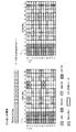
まず、図1を参照して、LTEシステムの後継システムで適用される参照信号の1つであるCSI-RSについて説明する。CSI−RSは、チャネル状態としてのCQI(Channel Quality Indicator)、PMI(Precoding Matrix Indicator)、RI(Rank Indicator)等のCSI測定に用いられる参照信号である。CSI−RSは、全てのサブフレームに割り当てられるCRSと異なり、所定の周期、例えば10サブフレーム周期で割り当てられる。また、CSI-RSは、位置、系列および送信電力というパラメータで特定される。CSI-RSの位置には、サブフレームオフセット、周期、サブキャリア−シンボルオフセット(インデックス)が含まれる。 First, with reference to FIG. 1, CSI-RS which is one of the reference signals applied with the successor system of a LTE system is demonstrated. CSI-RS is a reference signal used for CSI measurement such as CQI (Channel Quality Indicator), PMI (Precoding Matrix Indicator), and RI (Rank Indicator) as channel states. CSI-RS is assigned at a predetermined period, for example, 10 subframe periods, unlike CRS assigned to all subframes. The CSI-RS is specified by parameters such as position, sequence, and transmission power. The position of CSI-RS includes a subframe offset, a period, and a subcarrier-symbol offset (index).
CSI-RSは、LTEで規定される1リソースブロックにおいて、PDCCH(Physical Downlink Control Channel)等の制御信号、PDSCH(Physical Downlink Shared Channel)等のユーザデータ、CRS(Cell-specific Reference Signal)やDM−RS(Demodulation − Reference Signal)等の他の参照信号と重ならないように割り当てられる。1リソースブロックは、周波数方向に連続する12サブキャリアと、時間軸方向に連続する14シンボルとで構成される。PAPRを抑制する観点から、CSI-RSを送信可能なリソースは、時間軸方向に隣接する2つのリソースエレメントがセットで割り当てられる。 The CSI-RS is a control signal such as PDCCH (Physical Downlink Control Channel), user data such as PDSCH (Physical Downlink Shared Channel), CRS (Cell-specific Reference Signal) and DM- in one resource block defined by LTE. It is assigned so as not to overlap with other reference signals such as RS (Demodulation-Reference Signal). One resource block includes 12 subcarriers continuous in the frequency direction and 14 symbols continuous in the time axis direction. From the viewpoint of suppressing PAPR, two resource elements adjacent in the time axis direction are assigned as a set to resources that can transmit CSI-RS.
図1に示されるCSI-RS構成では、CSI-RS用リソース(参照信号用リソース)として40リソースエレメントが確保されている。この40リソースエレメントには、CSI-RSポート数(アンテナ数)に応じてCSI-RSパターンが設定される。各CSI−RSパターンでは、1つのCSI−RSポートにつき、1つのリソースエレメントがCSI−RS用に割り当てられる。CSI-RSポート数が2の場合、40リソースエレメントの中の2つのリソースエレメントにCSI-RSが割り当てられる。よって、図1(a)では、インデックス#0−#19(CSI Configuration=0-19)で示される20パターンのCSI−RSパターンが設定される。ここでは、説明の便宜上、1パターンを構成するリソースエレメントに同一のインデックスを付している。
In the CSI-RS configuration shown in FIG. 1, 40 resource elements are secured as CSI-RS resources (reference signal resources). In this 40 resource element, a CSI-RS pattern is set according to the number of CSI-RS ports (number of antennas). In each CSI-RS pattern, one resource element is allocated for CSI-RS per one CSI-RS port. When the number of CSI-RS ports is 2, CSI-RS is allocated to two resource elements out of 40 resource elements. Therefore, in FIG. 1A, 20 CSI-RS patterns indicated by
CSI-RSポート数が4の場合、40リソースエレメントの中の4つのリソースエレメントにCSI-RSが割り当てられる。よって、図1(b)では、インデックス#0−#9(CSI Configuration=0-9)で示される10パターンのCSI−RSパターンが設定される。CSI-RSポート数が8の場合、40リソースエレメントの中の8つのリソースエレメントにCSI-RSが割り当てられる。よって、図1(c)に示すように、インデックス#0−#4(CSI Configuration=0-4)で示される5パターンのCSI−RSパターンが設定される。なお、CSI−RSパターンにおいて、CSI−RSが割り当てられなかったリソースエレメントには、ユーザデータが割り当てられる。
When the number of CSI-RS ports is 4, CSI-RS is allocated to 4 resource elements out of 40 resource elements. Therefore, in FIG. 1B, 10 CSI-RS patterns indicated by
そして、CSI−RSは、セル毎に異なるCSI−RSパターン(CSI Configuration)が選択されることで、セル間での干渉が抑えられている。また、CSI-RSパターンは、図1(a)−(c)に示すFDDのノーマルパターンの他、図1(d)に示すように、FDDのオプションとしてTDDのアディショナルパターンを加えたパターンでもよい。また、FDDのノーマルパターンを拡張した不図示のエクステンデッドパターンでもよい。以下の説明では、説明の便宜上、FDDのノーマルパターンを例示して説明する。 In CSI-RS, interference between cells is suppressed by selecting a different CSI-RS pattern (CSI Configuration) for each cell. In addition to the FDD normal patterns shown in FIGS. 1A to 1C, the CSI-RS pattern may be a pattern obtained by adding an additional TDD pattern as an FDD option, as shown in FIG. 1D. . Also, an extended pattern (not shown) obtained by expanding the normal pattern of FDD may be used. In the following description, a normal pattern of FDD will be described as an example for convenience of description.
ところで、CSI−RSを用いたCSI測定においては、隣接セルからのデータ干渉により測定精度が劣化する場合がある。例えば、図2(a)に示すように、セルC1の下りリンクのリソースブロックに、隣接セルC2のCSI−RSに対応してユーザデータが割り当てられている。また、セルC2の下りリンクのリソースブロックに、隣接セルC1のCSI−RSに対応してユーザデータが割り当てられている。これらユーザデータは、各セルにおけるCSI−RSの干渉成分を構成し、セルC1及びセルC2の境界に位置する移動端末装置におけるCSIの測定精度を劣化させる要因となる。 By the way, in CSI measurement using CSI-RS, measurement accuracy may deteriorate due to data interference from adjacent cells. For example, as shown in FIG. 2 (a), user data is allocated to the downlink resource block of the cell C1 corresponding to the CSI-RS of the adjacent cell C2. Further, user data is allocated to the downlink resource block of the cell C2 corresponding to the CSI-RS of the adjacent cell C1. These user data constitute an interference component of CSI-RS in each cell, and cause deterioration in CSI measurement accuracy in a mobile terminal apparatus located at the boundary between the cells C1 and C2.
ユーザデータの割り当て位置に起因するCSIの測定精度の劣化を改善するため、ミューティングが検討されている。ミューティングにおいては、図2(b)に示すように、隣接セルのCSI−RSに対応するリソースにユーザデータが割り当てられない。セルC1の下りリンクのリソースブロックは、セルC2のCSI−RSに対応してミューティングされる。また、セルC2の下りリンクのリソースブロックは、セルC1のCSI−RSに対応してミューティングされる。 Muting is being studied in order to improve the degradation of CSI measurement accuracy caused by the user data allocation position. In muting, as shown in FIG.2 (b), user data is not allocated to the resource corresponding to CSI-RS of an adjacent cell. The downlink resource block of the cell C1 is muted corresponding to the CSI-RS of the cell C2. Further, the downlink resource block of the cell C2 is muted corresponding to the CSI-RS of the cell C1.
この構成により、隣接セルのユーザデータに起因するCSI−RSの干渉成分を排除して、移動端末装置におけるCSIの測定精度を改善する。隣接セル間で相互にミューティングを行う場合には、隣接セルのために自セルのデータチャネルを無送信とすることから、移動端末装置に対してミューティングの位置を通知する必要がある。これは、基地局装置がミューティングされるリソースを避けてレートマッチングするため、移動端末装置がミューティングされるリソースを認識してデレートマッチングする必要があるためである。移動端末装置が、ミューティングされるリソースを認識しないと、ミューティングされるリソースに対しても復調処理がされるため、復調処理のスループットおよび復調精度が劣化する。 With this configuration, the CSI-RS interference component caused by the user data of the neighboring cell is eliminated, and the CSI measurement accuracy in the mobile terminal apparatus is improved. When mutual muting is performed between adjacent cells, it is necessary to notify the mobile terminal device of the muting position because the data channel of the own cell is not transmitted for the adjacent cells. This is because the base station apparatus performs rate matching while avoiding resources to be muted, and the mobile terminal apparatus needs to recognize resources to be muted and perform derate matching. If the mobile terminal apparatus does not recognize the resource to be muted, the demodulation process is also performed on the muted resource, so that the throughput and demodulation accuracy of the demodulation process deteriorate.
なお、ミューティングされるリソースは、全くデータが割り当てられないリソースとして規定されてもよいし、隣接セルのCSI−RSに干渉を与えない程度にデータが割り当てられるリソースとして規定されてもよい。さらに、ミューティングされたリソースは、隣接セルのCSI−RSに対して干渉を与えない程度の送信電力で送信されるリソースとして規定されてもよい。 Note that the resource to be muted may be defined as a resource to which no data is allocated, or may be defined as a resource to which data is allocated to an extent that does not interfere with CSI-RSs of neighboring cells. Furthermore, the muted resource may be defined as a resource that is transmitted with a transmission power that does not interfere with the CSI-RS of the neighboring cell.
基地局装置が、移動端末装置に対してミューティングを通知する場合には、CSI−RSパターンを用いて通知する。この場合、CSI−RSパターンにナンバリングされるインデックス(CSI Configuration)とミューティングの有無とを1対1で対応付けしたビットマップ形式でミューティングを通知してもよい。また、ミューティングの通知とCSI−RSの通知とで、CSI−RSポート数が異なるCSI−RSパターンを使用してもよい。 When a base station apparatus notifies muting with respect to a mobile terminal apparatus, it notifies using a CSI-RS pattern. In this case, the muting may be notified in a bitmap format in which an index (CSI Configuration) numbered in the CSI-RS pattern and the presence / absence of muting are associated one-to-one. Moreover, you may use the CSI-RS pattern from which the number of CSI-RS ports differs by the notification of muting and the notification of CSI-RS.
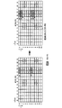
図3では、CSI−RSポート数が4の場合のCSI−RSパターンを用いて、ミューティングを通知する例を示している。ここでは、インデックス#1、#6(CSI Configuration=1,6)で示されるCSI−RS用リソースにミューティングが設定されている。この場合、図1(d)に示すFDDのノーマルパターンにTDDのアディショナルパターンを加えたインデックス[#0−#9、#20−#25](CSI Configuration=0-9,20-25)に対応させて、16ビットのビットマップ情報[0100001000000000]が通知される。ビットマップ情報では、ミューティングされるリソースには“1”がセットされ、ミューティングされないリソースには“0”がセットされる。また、基地局装置は、ビットマップ情報の他に、送信周期(Duty Cycle)、サブフレームオフセットを移動端末装置に対して通知する。
In FIG. 3, the example which notifies muting using the CSI-RS pattern in case the number of CSI-RS ports is four is shown. Here, muting is set for the CSI-RS resources indicated by
また、図3では、CSI−RSポート数が2の場合のCSI−RSパターンを用いてCSI−RSを通知している。ここでは、図1(a)のインデックス#1(CSI Configuration=1)で示されるCSI−RS用リソースにCSI−RSが割り当てられる。したがって、ビットマップ情報で示されるミューティングリソースのうち、CSI−RSが割り当てられるリソースを除いて、ミューティングが設定される。基地局装置は、ミューティング情報に加えてCSI−RSが割り当てられるリソースを移動端末装置に対して通知する。 Moreover, in FIG. 3, CSI-RS is notified using the CSI-RS pattern in case the number of CSI-RS ports is two. Here, the CSI-RS is assigned to the CSI-RS resource indicated by index # 1 (CSI Configuration = 1) in FIG. Accordingly, muting is set except for resources to which CSI-RS is allocated among muting resources indicated by the bitmap information. The base station apparatus notifies the mobile terminal apparatus of resources to which CSI-RS is allocated in addition to muting information.
ところで、CSI−RSは、上記したようにCRS等と比較して長い周期(複数サブフレームに1回)で送信される。また、CSI−RSは、1つのCSI−RSポートにつき、1つのリソースエレメントが割り当てられており、CRS等と比較して割り当てられるリソースエレメント数が少ない。これは、データ復調に用いるチャネル推定に必要な参照信号に比べて、CSIの測定に必要な1無線リソースあたりの参照信号数(密度、存在割合)が低く設定されるからである。このように、1無線リソースあたりのCSI−RSの数が少ないため、将来のシステムで移動端末装置から高精度なフィードバックが必要となる場合には、移動端末装置が十分なチャネル推定をできない可能性がある。 By the way, the CSI-RS is transmitted in a longer cycle (once in a plurality of subframes) than the CRS or the like as described above. Further, in CSI-RS, one resource element is assigned to one CSI-RS port, and the number of assigned resource elements is smaller than that of CRS or the like. This is because the number of reference signals (density and existence ratio) per radio resource necessary for CSI measurement is set lower than the reference signal necessary for channel estimation used for data demodulation. As described above, since the number of CSI-RSs per radio resource is small, there is a possibility that the mobile terminal device cannot perform sufficient channel estimation when a highly accurate feedback is required from the mobile terminal device in a future system. There is.
この問題を解決するために、図4に示すように、単純にCSI−RS数を増やして、1無線リソースにおけるCSI−RSの存在割合(密度)を増加することが考えられる。しかしながら、存在割合の増加に対応した新たな移動端末装置は、CSI−RSを基地局装置から受信できるが、既存の移動端末装置は、追加のCSI−RSを認識できずユーザデータの復調時に干渉となる。 In order to solve this problem, as shown in FIG. 4, it is conceivable to simply increase the number of CSI-RSs and increase the presence ratio (density) of CSI-RSs in one radio resource. However, a new mobile terminal apparatus corresponding to the increase in the existence ratio can receive CSI-RS from the base station apparatus, but the existing mobile terminal apparatus cannot recognize additional CSI-RS and interferes with demodulation of user data. It becomes.
例えば、図4の例では、CSI−RSポート数が4の場合に、インデックス#1(CSI Configuration=1)に示すCSI−RS用リソースに加えて、インデックス#6(CSI Configuration=6)に示すCSI−RS用リソースにCSI−RSが割り当てられている。新たな移動端末装置に対しては、例えば、CSI−RSパターンを新たに定義することで、インデックス#1、#6(CSI Configuration=1,6)のCSI−RSを受信させることが可能である。一方、既存の移動端末装置に対しては、CSI−RSパターンを新たに定義できないため、インデックス#6(CSI Configuration=6)のCSI−RSを認識させることができない。
For example, in the example of FIG. 4, when the number of CSI-RS ports is 4, in addition to the resource for CSI-RS indicated by index # 1 (CSI Configuration = 1), the index is indicated by index # 6 (CSI Configuration = 6). A CSI-RS is assigned to a CSI-RS resource. For a new mobile terminal device, for example, by newly defining a CSI-RS pattern, it is possible to receive CSI-RSs with
そこで、本発明者らは、これらの問題を解決するために、本発明に至った。すなわち、本発明の骨子は、新たな移動端末装置に対しては、既存のCSI−RSと共に追加のCSI−RSが割り当てられるリソースを通知し、既存の移動端末装置に対しては、ミューティングによって追加のCSI−RSを除いた、既存のCSI−RSが割り当てられるリソースを通知することである。これにより、既存の移動端末装置に悪影響を与えることなく、CSI−RSの存在割合を増加することができ、新たな移動端末装置にCSI−RSを高精度に測定させることができる。 Therefore, the present inventors have arrived at the present invention to solve these problems. That is, the essence of the present invention is to notify a new mobile terminal device of resources to which an additional CSI-RS is allocated together with the existing CSI-RS, and to an existing mobile terminal device by muting. It is to notify resources to which existing CSI-RSs are allocated, excluding additional CSI-RSs. Thereby, the presence ratio of CSI-RS can be increased without adversely affecting the existing mobile terminal apparatus, and the new mobile terminal apparatus can be made to measure CSI-RS with high accuracy.
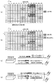
ここで、本実施の形態におけるCSI−RSの位置情報のシグナリング方法について説明する。図5は、CSI−RSの位置情報のシグナリング方法の一例を示す図である。なお、以下の説明では、新たな移動端末装置を第1の移動端末装置とし、既存の移動端末装置を第2の移動端末装置として説明する。また、第1の移動端末装置及び第2の移動端末装置は、同一セル内に位置するものとする。なお、以下の説明では、1リソースブロック内のCSI−RSの存在割合について説明するが、1無線リソース内のCSI−RSの存在割合であればよく、例えば、複数サブフレーム内のCSI−RSの存在割合、1無線フレーム内のCSI−RSの存在割合に置き換えてもよい。 Here, a signaling method of CSI-RS location information in the present embodiment will be described. FIG. 5 is a diagram illustrating an example of a signaling method of CSI-RS location information. In the following description, a new mobile terminal device is described as a first mobile terminal device, and an existing mobile terminal device is described as a second mobile terminal device. Further, the first mobile terminal device and the second mobile terminal device are assumed to be located in the same cell. In the following description, the existence ratio of CSI-RS in one resource block will be described. However, the existence ratio of CSI-RS in one radio resource may be any, for example, CSI-RS in a plurality of subframes. The existence ratio may be replaced with the existence ratio of CSI-RS in one radio frame.
図5(a)は、第1の移動端末装置に対するCSI−RSの割り当て例を示している。ここでは、1リソースブロック内にCSI−RS用リソースとして40リソースエレメントが確保されている。また、1つのCSI−RSポートにつき2つのリソースエレメントがCSI−RS用に割り当てられ、1リソースブロック内のCSI−RSの存在割合が高められている。図の例では、CSI−RSポート数が4の場合に、インデックス#1(CSI Configuration=1)に加えてインデックス#6(CSI Configuration=6)で示されるリソースにCSI−RSが割り当てられている。 Fig.5 (a) has shown the example of allocation of CSI-RS with respect to a 1st mobile terminal device. Here, 40 resource elements are secured as CSI-RS resources in one resource block. In addition, two resource elements are allocated for CSI-RS for one CSI-RS port, and the presence ratio of CSI-RS in one resource block is increased. In the example of the figure, when the number of CSI-RS ports is 4, CSI-RS is allocated to the resource indicated by index # 6 (CSI Configuration = 6) in addition to index # 1 (CSI Configuration = 1). .
このように、第1の移動端末装置は、1リソースブロック内で、1つのCSI−RSポートにつき2つのCSI−RSを受信可能となっている。基地局装置は、第1の移動端末装置に対しては、CSI−RSが割り当てられる全てのリソースを通知する。これにより、第1の移動端末装置は、高い精度でCSIを測定できる。なお、追加のCSI−RSは、CSI−RSのセル間干渉を抑制するため、隣接セルのCSI−RSを避けて割り当てられる。この場合、セル間のCSI−RSの位置情報は、隣接する基地局装置間で予め規定されてもよいし、隣接する基地局装置間で動的に変更されてもよい。 As described above, the first mobile terminal apparatus can receive two CSI-RSs for one CSI-RS port within one resource block. The base station apparatus notifies all resources to which CSI-RS is allocated to the first mobile terminal apparatus. Thereby, the first mobile terminal apparatus can measure CSI with high accuracy. In addition, in order to suppress the inter-cell interference of CSI-RS, additional CSI-RS is allocated avoiding CSI-RS of an adjacent cell. In this case, the position information of CSI-RS between cells may be defined in advance between adjacent base station apparatuses, or may be dynamically changed between adjacent base station apparatuses.
一方、図5(b)に示すように、第2の移動端末装置は、1リソースブロック内で、1つのCSI−RSポートにつき1つのCSI−RSを受信可能となっている。このため、第2の移動端末装置は、リソースブロック内に割り当てられる全てのCSI−RSを受信することができない。そこで、基地局装置は、第2の移動端末装置に対しては、追加のCSI−RSが割り当てられるリソースをミューティングされるリソースとして通知する。図の例では、CSI−RSポート数が4の場合に、インデックス#6(CSI Configuration=6)で示されるリソースをミューティングされるリソースとして通知する。 On the other hand, as shown in FIG. 5B, the second mobile terminal apparatus can receive one CSI-RS per CSI-RS port within one resource block. For this reason, the second mobile terminal apparatus cannot receive all CSI-RSs allocated in the resource block. Therefore, the base station apparatus notifies the second mobile terminal apparatus of resources to which the additional CSI-RS is assigned as muted resources. In the example of the figure, when the number of CSI-RS ports is 4, the resource indicated by index # 6 (CSI Configuration = 6) is notified as a muted resource.
この場合、インデックス#6(CSI Configuration=6)で示されるリソースには、実際にはCSI−RSが割り当てられるが、第2の移動端末装置にはミューティングされるリソースとして認識される。よって、第2の移動端末装置は、インデックス#6(CSI Configuration=6)で示されるリソースに割り当てられたCSI−RSを無視して、インデックス#1(CSI Configuration=1)で示されるリソースに割り当てられたCSI−RSだけを受信する。また、第2の移動端末装置は、ユーザデータの復調時に、インデックス#6(CSI Configuration=6)に示されるCSI−RSを無視するため、ユーザデータの復調精度及びスループットが低下することがない。 In this case, although the CSI-RS is actually assigned to the resource indicated by index # 6 (CSI Configuration = 6), the second mobile terminal apparatus recognizes it as a resource to be muted. Therefore, the second mobile terminal apparatus ignores the CSI-RS assigned to the resource indicated by index # 6 (CSI Configuration = 6) and assigns it to the resource indicated by index # 1 (CSI Configuration = 1). Only received CSI-RS is received. Further, since the second mobile terminal apparatus ignores CSI-RS indicated by index # 6 (CSI Configuration = 6) when demodulating user data, the demodulation accuracy and throughput of user data are not reduced.
なお、本実施の形態では、第1の通知方法及び第2の通知方法により基地局装置から移動端末装置にCSI−RSの位置情報が通知される。第1の通知方法は、CSI−RSの位置情報を基地局装置から第1、第2の移動端末装置に対して個別に通知する方法である。第2の通知方法は、CSI−RSの位置情報を基地局装置から第1、第2の移動端末装置に対して一斉に通知する方法である。 In the present embodiment, the location information of CSI-RS is notified from the base station apparatus to the mobile terminal apparatus by the first notification method and the second notification method. The first notification method is a method in which CSI-RS position information is individually notified from the base station apparatus to the first and second mobile terminal apparatuses. The second notification method is a method of simultaneously reporting CSI-RS position information from the base station apparatus to the first and second mobile terminal apparatuses.
図5(c)に示すように、第1の通知方法では、基地局装置は、第1の移動端末装置に対してはCSI−RSの位置情報を個別に通知する。さらに、基地局装置は、第2の移動端末装置に対しては、CSI−RSの位置情報を個別に通知する際に、追加のCSI−RSの位置情報に代えてミューティング情報を通知する。この場合、基地局装置は、上記したCSI−RSパターンを利用して通知する。 As shown in FIG.5 (c), in a 1st notification method, a base station apparatus notifies the positional information on CSI-RS separately with respect to a 1st mobile terminal device. Further, the base station apparatus notifies the second mobile terminal apparatus of the muting information instead of the additional CSI-RS position information when individually reporting the position information of the CSI-RS. In this case, the base station apparatus notifies using the above CSI-RS pattern.
例えば、基地局装置は、CSI−RSパターンを示すCSI Configurationにより、第1、第2の移動端末装置に対して、CSI−RSが配置されるリソースを個別に通知してもよい。図5に示す例は、CSI−RSパターンが10パターンであるため、各CSI−RSの位置情報を通知するのに10通りのCSI Configurationを使用する。基地局装置は、第1の移動端末装置に対しては、CSI−RSの位置情報としてインデックス#1、#6を示すCSI Configuration=1,6を通知する。また、基地局装置は、第2の移動端末装置に対しては、インデックス#1を示すCSI Configuration=1を通知すると共にミューティング情報を通知する。
For example, the base station apparatus may individually notify the resources in which the CSI-RS is arranged to the first and second mobile terminal apparatuses by CSI Configuration indicating the CSI-RS pattern. In the example shown in FIG. 5, since there are 10 CSI-RS patterns, 10 CSI Configurations are used to notify the location information of each CSI-RS. The base station apparatus notifies the first mobile terminal apparatus of CSI Configuration = 1,6 indicating
この場合、基地局装置は、第2の移動端末装置に対しては、上述したビットマップ形式によりミューティング情報を個別に通知してもよい。基地局装置は、ノーマルパターンにアディショナルパターンを加えたインデックス[#0−#9、#20−#25](CSI Configuration=0-9,20-25)に対応させて、ミューティング情報として16ビットのビットマップ情報[0000001000000000]を通知する。ビットマップ情報では、ミューティングされるリソースには“1”がセットされ、ミューティングされないリソースには“0”がセットされる。なお、ビットマップ情報では、ミューティングリソースには“0”がセットされ、ミューティングされないリソースには“1”がセットされてもよい。また、ビットマップ情報を16ビットで構成したが、アディショナルパターンを除いた10ビットで構成してもよい。 In this case, the base station apparatus may individually notify the second mobile terminal apparatus of muting information in the bitmap format described above. The base station apparatus has 16 bits as muting information corresponding to an index [# 0- # 9, # 20- # 25] (CSI Configuration = 0-9, 20-25) obtained by adding an additional pattern to a normal pattern. Of the bitmap information [0000001000000000]. In the bitmap information, “1” is set for resources to be muted, and “0” is set for resources that are not muted. In the bitmap information, “0” may be set for muting resources, and “1” may be set for resources that are not muted. Moreover, although the bitmap information is composed of 16 bits, it may be composed of 10 bits excluding the additional pattern.
また、図5(d)に示すように、第2の通知方法では、基地局装置は、第1、第2の移動端末装置に対して、CSI−RSの位置情報を一斉に通知する際に、追加のCSI−RSの位置情報に代えてミューティング情報を通知する。さらに、基地局装置は、第1の移動端末装置に対してのみ追加のCSI−RSの位置情報を個別に通知する。この場合、基地局装置は、上記したCSI−RSパターンを利用して通知する。 Further, as shown in FIG. 5 (d), in the second notification method, the base station device notifies the first and second mobile terminal devices of CSI-RS location information all at once. The muting information is notified instead of the additional CSI-RS position information. Further, the base station apparatus individually notifies additional CSI-RS position information only to the first mobile terminal apparatus. In this case, the base station apparatus notifies using the above CSI-RS pattern.
例えば、基地局装置は、CSI−RSパターンを示すCSI Configurationにより、第1、第2の移動端末装置に対してCSI−RSが配置されるリソースを一斉に通知してもよい。図5に示す例では、基地局装置は、第1、第2の移動端末装置に対して、インデックス#1を示すCSI Configuration=1を通知する。また、基地局装置は、第1、第2の移動端末装置に対して、上述したビットマップ形式によりミューティング情報を一斉に通知してもよい。この場合、基地局装置は、ミューティング情報として16ビットのビットマップ情報[0000001000000000]を通知する。
For example, the base station apparatus may notify the resources where the CSI-RS is arranged to the first and second mobile terminal apparatuses all at once by CSI Configuration indicating the CSI-RS pattern. In the example illustrated in FIG. 5, the base station apparatus notifies CSI Configuration = 1 indicating
さらに、基地局装置は、CSI−RSパターンを示すCSI Configurationにより、第1の移動端末装置に対して追加のCSI−RSが配置されるリソースを個別に通知してもよい。図5に示す例では、基地局装置は、第1の移動端末装置に対して、インデックス#6を示すCSI Configuration=6を通知する。
Further, the base station apparatus may individually notify the resource in which the additional CSI-RS is arranged to the first mobile terminal apparatus by CSI Configuration indicating the CSI-RS pattern. In the example illustrated in FIG. 5, the base station apparatus notifies CSI Configuration = 6 indicating
また、第1、第2の通知方法において、基地局装置は、CSI−RSが配置されるリソース、ミューティングリソースの他に、送信周期(Duty Cycle)、サブフレームオフセット等を第1、第2の移動端末装置に対して通知する。また、これらCSI−RSの位置情報等は、ハイヤレイヤシグナリングで通知されてもよいし、報知チャネル、制御チャネル、データチャネルで通知されてもよい。 Further, in the first and second notification methods, the base station apparatus sets a transmission cycle (Duty Cycle), a subframe offset, and the like in addition to a resource in which CSI-RS is arranged and a muting resource. To the mobile terminal device. Further, the location information of the CSI-RS may be notified by higher layer signaling, or may be notified by a broadcast channel, a control channel, and a data channel.
また、第1、第2の通知方法は、上記方法に限定されない。例えば、基地局装置は、第1、第2の移動端末装置に対してビットマップ形式によりCSI−RSの位置情報を通知してもよい。また、基地局装置は、第1、第2の移動端末装置に対してCSI−RSパターンを示すCSI Configurationによりミューティング情報を通知してもよい。 Further, the first and second notification methods are not limited to the above methods. For example, the base station apparatus may notify CSI-RS position information to the first and second mobile terminal apparatuses in a bitmap format. Further, the base station apparatus may notify the first and second mobile terminal apparatuses of muting information by CSI Configuration indicating a CSI-RS pattern.
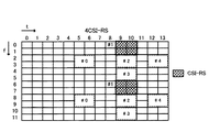
また、図6に示すように、CSI−RSパターンを新たに定義してもよい。例えば、CSI-RSポート数が4の場合に、インデックス#0−#4(CSI Configuration=0-4)で示される5パターンのCSI−RSパターンが設定されてもよい。これにより、基地局装置からのCSI−RSのシグナリング量を大幅に低減できる。また、図5及び図6に示すCSI−RSパターンにナンバリングされたインデックスは、一例であり適宜変更可能である。さらに、図5及び図6では、CSI−RSポート数が4の場合を例示したが、CSI−RSポート数が2及び8の場合でも同様な方法でシグナリングできる。 Moreover, as shown in FIG. 6, you may define a CSI-RS pattern newly. For example, when the number of CSI-RS ports is 4, five CSI-RS patterns indicated by indexes # 0- # 4 (CSI Configuration = 0-4) may be set. Thereby, the signaling amount of CSI-RS from a base station apparatus can be reduced significantly. Moreover, the index numbered by the CSI-RS pattern shown in FIG.5 and FIG.6 is an example, and can be changed suitably. 5 and 6 exemplify the case where the number of CSI-RS ports is 4, but even when the number of CSI-RS ports is 2 and 8, signaling can be performed in the same manner.
なお、第1の移動端末装置は、新たな移動端末装置に限定されず、1無線リソースにおいて高い存在割合で送信されるCSI−RSに対応すればよく、例えば、既存の移動端末装置でもよい。また、第2の移動端末装置は、既存の移動端末装置に限定されず、第1の移動端末装置によりも低い存在割合で送信されるCSI−RSに対応すればよく、例えば、新たな移動端末装置であってもよい。 Note that the first mobile terminal device is not limited to a new mobile terminal device, and may correspond to CSI-RS transmitted at a high presence rate in one radio resource, and may be, for example, an existing mobile terminal device. Further, the second mobile terminal device is not limited to the existing mobile terminal device, and may correspond to the CSI-RS transmitted at a lower rate than the first mobile terminal device. For example, a new mobile terminal device It may be a device.
ここで、本発明の実施例に係る無線通信システムについて詳細に説明する。図7は、本実施例に係る無線通信システムのシステム構成の説明図である。なお、図7に示す無線通信システムは、例えば、LTEシステム或いは、SUPER 3Gが包含されるシステムである。この無線通信システムでは、LTEシステムのシステム帯域を一単位とする複数の基本周波数ブロックを一体としたキャリアアグリゲーションが用いられている。また、この無線通信システムは、IMT−Advancedと呼ばれても良いし、4Gと呼ばれても良い。 Here, the wireless communication system according to the embodiment of the present invention will be described in detail. FIG. 7 is an explanatory diagram of the system configuration of the wireless communication system according to the present embodiment. Note that the radio communication system shown in FIG. 7 is a system including, for example, an LTE system or SUPER 3G. In this radio communication system, carrier aggregation in which a plurality of fundamental frequency blocks with the system band of the LTE system as a unit is integrated is used. Moreover, this radio | wireless communications system may be called IMT-Advanced, and may be called 4G.
図7に示すように、無線通信システム1は、基地局装置20A、20Bと、この基地局装置20A、20Bと通信する複数の第1、第2の移動端末装置10A、10Bとを含んで構成されている。基地局装置20A、20Bは、上位局装置30と接続され、この上位局装置30は、コアネットワーク40と接続される。また、基地局装置20A、20Bは、有線接続又は無線接続により相互に接続されている。第1、第2の移動端末装置10A、10Bは、セルC1、C2において基地局装置20A、20Bと通信を行うことができる。なお、上位局装置30には、例えば、アクセスゲートウェイ装置、無線ネットワークコントローラ(RNC)、モビリティマネジメントエンティティ(MME)等が含まれるが、これに限定されない。
As shown in FIG. 7, the
第1、第2の移動端末装置10A、10Bは、LTE端末及びLTE−A端末を含むが、以下においては、特段の断りがない限り第1、第2の移動端末装置として説明を進める。また、説明の便宜上、基地局装置20A、20Bと無線通信するのは第1、第2の移動端末装置10A、10Bであるものとして説明するが、より一般的には移動端末装置も固定端末装置も含むユーザ装置(UE:User Equipment)でよい。
The first and second mobile
無線通信システム1においては、無線アクセス方式として、下りリンクについてはOFDMA(直交周波数分割多元接続)が、上りリンクについてはSC−FDMA(シングルキャリア−周波数分割多元接続)が適用されるが、上りリンクの無線アクセス方式はこれに限定されない。OFDMAは、周波数帯域を複数の狭い周波数帯域(サブキャリア)に分割し、各サブキャリアにデータをマッピングして通信を行うマルチキャリア伝送方式である。SC−FDMAは、システム帯域を端末毎に1つ又は連続したリソースブロックからなる帯域に分割し、複数の端末が互いに異なる帯域を用いることで、端末間の干渉を低減するシングルキャリア伝送方式である。
In the
ここで、通信チャネルについて説明する。
下りリンクの通信チャネルは、第1、第2の移動端末装置10A、10Bで共有される下りデータチャネルとしてのPDSCH(Physical Downlink Shared Channel)と、下りL1/L2制御チャネル(PDCCH、PCFICH、PHICH)とを有する。PDSCHにより、送信データ及び上位制御情報が伝送される。PDCCH(Physical Downlink Control Channel)により、PDSCHおよびPUSCHのスケジューリング情報等が伝送される。PCFICH(Physical Control Format Indicator Channel)により、PDCCHに用いるOFDMシンボル数が伝送される。PHICH(Physical Hybrid-ARQ Indicator Channel)により、PUSCHに対するHARQのACK/NACKが伝送される。
Here, the communication channel will be described.
The downlink communication channel includes a PDSCH (Physical Downlink Shared Channel) as a downlink data channel shared by the first and second mobile
上りリンクの通信チャネルは、各移動端末装置で共有される上りデータチャネルとしてのPUSCH(Physical Uplink Shared Channel)と、上りリンクの制御チャネルであるPUCCH(Physical Uplink Control Channel)とを有する。このPUSCHにより、送信データや上位制御情報が伝送される。また、PUCCHにより、下りリンクの無線品質情報(CQI:Channel Quality Indicator)、ACK/NACK等が伝送される。 The uplink communication channel includes a PUSCH (Physical Uplink Shared Channel) as an uplink data channel shared by each mobile terminal apparatus and a PUCCH (Physical Uplink Control Channel) which is an uplink control channel. Transmission data and higher control information are transmitted by this PUSCH. Also, downlink radio quality information (CQI: Channel Quality Indicator), ACK / NACK, and the like are transmitted by PUCCH.
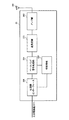
図8を参照しながら、本実施の形態に係る基地局装置の全体構成について説明する。なお、基地局装置20A、20Bは、同様な構成であるため、基地局装置20として説明する。また、第1、第2の移動端末装置10A、10Bも、同様な構成であるため、移動端末装置10として説明する。基地局装置20は、送受信アンテナ201と、アンプ部202と、送受信部(通知部)203と、ベースバンド信号処理部204と、呼処理部205と、伝送路インターフェース206とを備えている。下りリンクにより基地局装置20から移動端末装置に送信される送信データは、上位局装置30から伝送路インターフェース206を介してベースバンド信号処理部204に入力される。
The overall configuration of the base station apparatus according to the present embodiment will be described with reference to FIG. Note that the
ベースバンド信号処理部204において、下りデータチャネルの信号は、PDCPレイヤの処理、送信データの分割・結合、RLC(radio link control)再送制御の送信処理などのRLCレイヤの送信処理、MAC(Medium Access Control)再送制御、例えば、HARQの送信処理、スケジューリング、伝送フォーマット選択、チャネル符号化、逆高速フーリエ変換(IFFT:Inverse Fast Fourier Transform)処理、プリコーディング処理が行われる。また、下りリンク制御チャネルである物理下りリンク制御チャネルの信号に関しても、チャネル符号化や逆高速フーリエ変換等の送信処理が行われる。
In the baseband
また、ベースバンド信号処理部204は、報知チャネルにより、同一セルに接続する移動端末装置10に対して、各移動端末装置10が基地局装置20との無線通信するための制御情報を通知する。当該セルにおける通信のための情報には、例えば、上りリンク又は下りリンクにおけるシステム帯域幅や、PRACH(Physical Random Access Channel)におけるランダムアクセスプリアンブルの信号を生成するためのルート系列の識別情報(Root Sequence Index)等が含まれる。
Also, the baseband
送受信部203は、ベースバンド信号処理部204から出力されたベースバンド信号を無線周波数帯に変換する。アンプ部202は周波数変換された無線周波数信号を増幅して送受信アンテナ201へ出力する。
The transmission /
一方、上りリンクにより移動端末装置10から基地局装置20に送信される信号については、送受信アンテナ201で受信された無線周波数信号がアンプ部202で増幅され、送受信部203で周波数変換されてベースバンド信号に変換され、ベースバンド信号処理部204に入力される。
On the other hand, for a signal transmitted from the mobile
ベースバンド信号処理部204は、上りリンクで受信したベースバンド信号に含まれる送信データに対して、FFT処理、IDFT処理、誤り訂正復号、MAC再送制御の受信処理、RLCレイヤ、PDCPレイヤの受信処理を行う。復号された信号は伝送路インターフェース206を介して上位局装置30に転送される。
The baseband
呼処理部205は、通信チャネルの設定や解放等の呼処理や、基地局装置20の状態管理や、無線リソースの管理を行う。
The
次に、図9を参照しながら、本実施の形態に係る移動端末装置の全体構成について説明する。LTE端末もLTE-A端末もハードウエアの主要部構成は同じであるので、区別せずに説明する。移動端末装置10は、送受信アンテナ101と、アンプ部102と、送受信部(受信部)103と、ベースバンド信号処理部104と、アプリケーション部105とを備えている。
Next, the overall configuration of the mobile terminal apparatus according to the present embodiment will be described with reference to FIG. Since the LTE main unit and the LTE-A terminal have the same hardware configuration, they will be described without distinction. The mobile
下りリンクのデータについては、送受信アンテナ101で受信された無線周波数信号がアンプ部102で増幅され、送受信部103で周波数変換されてベースバンド信号に変換される。このベースバンド信号は、ベースバンド信号処理部104でFFT処理や、誤り訂正復号、再送制御の受信処理等がなされる。この下りリンクのデータの内、下りリンクの送信データは、アプリケーション部105に転送される。アプリケーション部105は、物理レイヤやMACレイヤより上位のレイヤに関する処理等を行う。また、下りリンクのデータの内、報知情報も、アプリケーション部105に転送される。
As for downlink data, a radio frequency signal received by the transmission /
一方、上りリンクの送信データは、アプリケーション部105からベースバンド信号処理部104に入力される。ベースバンド信号処理部104においては、マッピング処理、再送制御(HARQ)の送信処理や、チャネル符号化、DFT処理、IFFT処理を行う。送受信部103は、ベースバンド信号処理部104から出力されたベースバンド信号を無線周波数帯に変換する。その後、アンプ部102は、周波数変換された無線周波数信号を増幅して送受信アンテナ101より送信する。
On the other hand, uplink transmission data is input from the
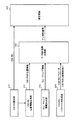
図10を参照して、基地局装置の機能ブロックについて説明する。なお、図10の各機能ブロックは、主にベースバンド処理部の処理内容である。また、図10の機能ブロック図は、簡略化したものであり、ベースバンド処理部において通常備える構成を備えるものとする。 With reference to FIG. 10, the functional block of a base station apparatus is demonstrated. Note that each functional block in FIG. 10 is mainly processing contents of the baseband processing unit. Further, the functional block diagram of FIG. 10 is simplified, and is assumed to have a configuration normally provided in the baseband processing unit.
図10に示す第1の通知方法では、基地局装置20は、CSI−RS割当部211と、CSI−RS位置情報生成部212と、ミューティング情報生成部213と、CSI−RSパラメータ生成部214と、下り制御信号生成部215と、送受信部203とを有している。
In the first notification method illustrated in FIG. 10, the
CSI−RS割当部211は、CSI-RS用リソースに、CSI−RSポート数に応じてCSI-RSを割り当てる。CSI−RS割当部211は、1つCSI−RSポートにつき2つのリソースエレメントにCSI−RSを配置して、1リソースブロック内のCSI−RSの存在割合を高めている。この場合、CSI−RS割当部211は、第2の移動端末装置10Bで受信可能なCSI−RSに、さらにCSI−RSを加えて第1の移動端末装置10Aの測定精度を高めるように割り当てる。
The CSI-
また、CSI−RS割当部211は、隣接セルからCSI−RSの位置情報を取得し、隣接セルのCSI−RSを避けて、追加のCSI−RSを割り当てる。これにより、1リソースブロック内のCSI−RSの存在割合を高めた場合でも、隣接セル間でのCSI−RSの干渉が抑えられる。
In addition, the CSI-
CSI−RS位置情報生成部212は、CSI−RS割当部211によって割り当てられたCSI−RSの位置情報を生成する。CSI−RSの位置情報としては、CSI−RSが割り当てられるリソースの他に、送信周期(Duty Cycle)、サブフレームオフセット等が含まれる。CSI−RSが割り当てられるリソースは、CSI Configurationやビットマップ情報等により特定される。CSI−RSの位置情報は、CSI−RSパラメータの一つとして下り制御信号生成部215に入力される。
The CSI-RS position
ミューティング情報生成部213は、追加のCSI−RSを割り当てるリソースがミューティングされることを示すミューティング情報を生成する。このミューティング情報に示されるリソースは、実際にはCSI−RSが割り当てられており、ミューティングされていない。ミューティング情報としては、ビットマップ情報やCSI Configurationが生成される。ミューティング情報は、下り制御信号生成部215に入力される。
The muting
CSI−RSパラメータ生成部214は、CSI−RSの位置情報以外のCSI−RSの系列や送信電力等のパラメータを生成する。CSI−RSパラメータ生成部214に生成されたCSI−RSパラメータは、下り制御信号生成部215に入力される。
The CSI-RS
下り制御信号生成部215は、第1の移動端末装置10Aに対しては、CSI−RSの位置情報及びCSI−RSパラメータを含めて下り制御信号を生成する。これにより、第1の移動端末装置10Aには、CSI−RSが割り当てられた全てのリソースが個別に通知される。また、下り制御信号生成部215は、第2の移動端末装置10Bに対しては、CSI−RSの位置情報、CSI−RSパラメータ、ミューティング情報を含めて下り制御信号を生成する。これにより、第2の移動端末装置10Bには、追加のCSI−RSがミューティングされるリソースとして認識され、受信可能な一部のCSI−RSのリソースが個別に通知される。送受信部203は、CSI−RS及び下り制御信号を第1、第2の移動端末装置10A、10Bに送信する。
The downlink control
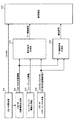
図11を参照して、第1、第2の移動端末装置の機能ブロックについて説明する。なお、図11の各機能ブロックは、主にベースバンド処理部の処理内容である。また、図11の機能ブロック図は、簡略化したものであり、ベースバンド処理部において通常備える構成を備えるものとする。 With reference to FIG. 11, the functional blocks of the first and second mobile terminal apparatuses will be described. Note that each functional block in FIG. 11 is mainly processing contents of the baseband processing unit. Further, the functional block diagram of FIG. 11 is simplified, and is assumed to have a configuration normally provided in the baseband processing unit.
図11に示すように、第1の移動端末装置10Aは、送受信部103Aと、取得部111Aと、測定部112Aと、ユーザデータ復調部113Aとを有している。送受信部103Aは、基地局装置20からCSI−RS及び下り制御信号を受信する。取得部111Aは、下り制御信号を復調して信号の中身を解析することで、CSI−RSの位置情報及びCSI−RSパラメータを取得する。
As shown in FIG. 11, the first mobile
測定部112Aは、CSI−RSの位置情報、系列、送信電力等のパラメータからCSIを測定する。この場合、測定部112Aは、基地局装置20からCSI−RSが割り当てられた全てのリソースが通知されるため、高精度にCSIを測定できる。ユーザデータ復調部113Aは、送受信部103Aを介して受信したユーザデータを復調する。なお、第1の移動端末装置10Aは、ハイヤレイヤシグナリングにより、CSI−RSの位置情報、CSI−RSパラメータを受信する構成としてもよい。
The
また、第2の移動端末装置10Bは、送受信部103Bと、取得部111Bと、測定部112Bと、ユーザデータ復調部113Bとを有している。送受信部103Bは、基地局装置20からCSI−RS及び下り制御信号を受信する。取得部111Bは、下り制御信号を復調して信号の中身を解析することで、CSI−RSの位置情報、CSI−RSパラメータ、ミューティング情報を取得する。
The second mobile
測定部112Bは、CSI−RSの位置情報、系列、送信電力等のパラメータからCSIを測定する。ユーザデータ復調部113Bは、送受信部103Bを介して受信したユーザデータを復調する。この場合、ユーザデータ復調部113Bは、基地局装置20から通知されたミューティング情報により、追加のCSI−RSが割り当てられたリソースをミューティングされたリソースとして認識する。このため、ユーザデータ復調部113Bが、追加のCSI−RSを復調することがなく、復調処理のスループットおよび復調精度が向上される。なお、第2の移動端末装置10Bは、ハイヤレイヤシグナリングにより、CSI−RSの位置情報、CSI−RSパラメータ、ミューティング情報を受信する構成としてもよい。
The measurement unit 112B measures CSI from parameters such as CSI-RS position information, series, and transmission power. The user
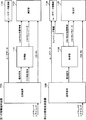
図12を参照して、基地局装置の機能ブロックについて説明する。なお、図12の各機能ブロックは、主にベースバンド処理部の処理内容である。また、図12の機能ブロック図は、簡略化したものであり、ベースバンド処理部において通常備える構成を備えるものとする。また、図12は、図10と同一名称のブロックは、同一の符号を付して説明する。 With reference to FIG. 12, the functional block of a base station apparatus is demonstrated. Note that each functional block in FIG. 12 is mainly processing contents of the baseband processing unit. Further, the functional block diagram of FIG. 12 is simplified, and is assumed to have a configuration normally provided in the baseband processing unit. In FIG. 12, blocks having the same names as those in FIG.
図12に示す第2の通知方法では、基地局装置20は、CSI−RS割当部211と、CSI−RS位置情報生成部212と、ミューティング情報生成部213と、CSI−RSパラメータ生成部214と、報知信号生成部216と、下り制御信号生成部215と、送受信部203とを有している。
In the second notification method illustrated in FIG. 12, the
CSI−RS割当部211は、CSI-RS用リソースに、CSI−RSポート数に応じてCSI-RSを割り当てる。CSI−RS割当部211は、1つCSI−RSポートにつき2つのリソースエレメントにCSI−RSを配置して、1リソースブロック内のCSI−RSの存在割合を高めている。この場合、CSI−RS割当部211は、第2の移動端末装置10Bで受信可能なCSI−RSに、さらにCSI−RSを加えて第1の移動端末装置10Aの測定精度を高めるように割り当てる。
The CSI-
また、CSI−RS割当部211は、隣接セルからCSI−RSの位置情報を取得し、隣接セルのCSI−RSを避けて、追加のCSI−RSを割り当てる。これにより、1リソースブロック内のCSI−RSの存在割合を高めた場合でも、隣接セル間でのCSI−RSの干渉が抑えられる。
In addition, the CSI-
CSI−RS位置情報生成部212は、CSI−RS割当部211によって割り当てられたCSI−RSの位置情報を生成する。CSI−RSの位置情報としては、CSI−RSが割り当てられるリソースの他に、送信周期(Duty Cycle)、サブフレームオフセット等が含まれる。CSI−RSが割り当てられるリソースは、CSI Configurationやビットマップ情報等により特定される。CSI−RSの位置情報は、CSI−RSパラメータの一つとして報知信号生成部216及び下り制御信号生成部215に入力される。
The CSI-RS position
ミューティング情報生成部213は、追加のCSI−RSを割り当てるリソースがミューティングされることを示すミューティング情報を生成する。このミューティング情報に示されるリソースには、実際にはCSI−RSが割り当てられており、ミューティングされていない。ミューティング情報としては、ビットマップ情報やCSI Configurationが生成される。ミューティング情報は、下り制御信号生成部215に入力される。
The muting
CSI−RSパラメータ生成部214は、CSI−RSの位置情報以外のCSI−RSの系列や送信電力等のパラメータを生成する。CSI−RSパラメータ生成部214に生成されたCSI−RSパラメータは、報知信号生成部216及び下り制御信号生成部215に入力される。
The CSI-RS
報知信号生成部216は、第1、第2の移動端末装置10A、10Bに対して、第2の移動端末装置10Bで受信可能なCSI−RSの位置情報、CSI−RSパラメータ、追加のCSI−RSに対するミューティング情報を含めて報知信号を生成する。これにより、第1、第2の移動端末装置10A、10Bに対して、追加のCSI−RSがミューティングされるリソースとして認識され、一部のCSI−RSのリソースが一斉に通知される。
The broadcast
下り制御信号生成部215は、第1の移動端末装置10Aに対して、追加のCSI−RSの位置情報及びCSI−RSパラメータを含めて下り制御信号を生成する。これにより、第1の移動端末装置10Aには、ミューティングされるリソースのCSI−RSを認識させることができる。送受信部203は、CSI−RS及び下り制御信号を第1、第2の移動端末装置10A、10Bに送信する。
The downlink control
図13を参照して、第1、第2の移動端末装置の機能ブロックについて説明する。なお、図13の各機能ブロックは、主にベースバンド処理部の処理内容である。また、図13の機能ブロック図は、簡略化したものであり、ベースバンド処理部において通常備える構成を備えるものとする。また、図13は、図11と同一名称のブロックは、同一の符号を付して説明する。 With reference to FIG. 13, the functional blocks of the first and second mobile terminal apparatuses will be described. Note that each functional block in FIG. 13 is mainly the processing content of the baseband processing unit. Further, the functional block diagram of FIG. 13 is simplified, and is assumed to have a configuration normally provided in the baseband processing unit. In FIG. 13, blocks having the same names as those in FIG.
図13に示すように、第1の移動端末装置10Aは、送受信部103Aと、取得部111Aと、測定部112Aと、ユーザデータ復調部113Aとを有している。送受信部103Aは、基地局装置20からCSI−RS、報知信号、下り制御信号を受信する。取得部111Aは、報知信号を復調して信号の中身を解析することで、第2の移動端末装置10Bで受信可能なCSI−RSの位置情報、CSI−RSパラメータ、追加のCSI−RSに対するミューティング情報を取得する。また、取得部111Aは、下り制御信号を復調して信号の中身を解析することで、追加のCSI−RSの位置情報及びCSI−RSパラメータを取得する。これにより、第1の移動端末装置10Aは、ミューティング情報で示されるリソースに、CSI−RSが割り当てられることを認識する。
As illustrated in FIG. 13, the first mobile
測定部112Aは、CSI−RSの位置情報、系列、送信電力等のパラメータからCSIを測定する。この場合、測定部112Aは、基地局装置20からCSI−RSが割り当てられる全てのリソースが通知されるため、高精度にCSIを測定できる。ユーザデータ復調部113Aは、送受信部103Aを介して受信したユーザデータを復調する。なお、第1の移動端末装置10Aは、ハイヤレイヤシグナリングにより、CSI−RSの位置情報、CSI−RSパラメータを受信する構成としてもよい。
The
また、第2の移動端末装置10Bは、送受信部103Bと、取得部111Bと、測定部112Bと、ユーザデータ復調部113Bとを有している。送受信部103Bは、基地局装置20からCSI−RS及び報知信号を受信する。取得部111Bは、報知信号を復調して信号の中身を解析することで、第2の移動端末装置10Bで受信可能なCSI−RSの位置情報、CSI−RSパラメータ、追加のCSI−RSに対するミューティング情報を取得する。
The second mobile
測定部112Bは、CSI−RSの位置情報、系列、送信電力等のパラメータからCSIを測定する。ユーザデータ復調部113Bは、送受信部103Bを介して受信したユーザデータを復調する。この場合、ユーザデータ復調部113Bは、基地局装置20から通知されたミューティング情報により、追加のCSI−RSが割り当てられたリソースをミューティングされるリソースとして認識する。このため、ユーザデータ復調部113Bが、追加のCSI−RSを復調することがなく、復調処理のスループットおよび復調精度が向上される。なお、第2の移動端末装置10Bは、ハイヤレイヤシグナリングにより、CSI−RSの位置情報、CSI−RSパラメータ、ミューティング情報を受信する構成としてもよい。
The measurement unit 112B measures CSI from parameters such as CSI-RS position information, series, and transmission power. The user
以上のように、本実施の形態に係る基地局装置20によれば、第1の移動端末装置10Aが、1無線リソースにおいて高い存在割合で割り当てられる全てのCSI−RSを受信して、高い精度でチャネル状態を測定できる。また、第2の移動端末装置10Bが、第1の移動端末装置10Aが受信可能な存在割合で割り当てられるCSI−RSのうち、ミューティングされたリソースのCSI−RSを無視して、チャネル状態を測定できる。よって、CSI−RSの存在割合の増加によって、第2の移動端末装置が影響を受けることがない。このように、第1の移動端末装置10Aと第2の移動端末装置10Bとが混在する際に、CSI−RSを適切に送受信できる。
As described above, according to the
なお、上記した実施の形態においては、第1、第2の通知方法を例示したが、CSI−RSの位置情報の通知方法はこれに限定されるものではない。CSI−RSの位置情報の通知方法は、第1の移動端末装置に対しては、CSI−RSが割り当てられる全てのリソースを通知し、第2の移動端末装置に対しては、CSI−RSが割り当てられるリソースを通知する際に、一部のリソースをミューティングされるリソースとして通知する方法であればよい。 In the above-described embodiment, the first and second notification methods are illustrated, but the CSI-RS location information notification method is not limited to this. In the CSI-RS position information notification method, all resources to which CSI-RS is allocated are notified to the first mobile terminal apparatus, and CSI-RS is transmitted to the second mobile terminal apparatus. Any method may be used as long as it is a method of notifying some resources as resources to be muted when notifying the allocated resources.
また、上記した実施の形態においては、移動端末装置において、取得部がCSI−RSの位置情報、ミューティング情報、CSI−RSパラメータを取得する構成としたが、この構成に限定されるものではない。CSI−RSの位置情報、ミューティング情報、CSI−RSパラメータは、取得部以外の機能ブロック、例えば、測定部やユーザデータ復調部により取得される構成としてもよい。 In the above-described embodiment, the acquisition unit acquires the CSI-RS position information, muting information, and CSI-RS parameters in the mobile terminal device. However, the present invention is not limited to this configuration. . The CSI-RS position information, muting information, and CSI-RS parameters may be acquired by a functional block other than the acquisition unit, for example, a measurement unit or a user data demodulation unit.
また、上記した実施の形態においては、参照信号としてCSI−RSを例示したが、これに限定されるものではない。参照信号は、チャネル状態の測定に使用されるものであればよい。また、CSIは、CQI、PMI、RIの少なくとも1つを含むものであればよい。 Moreover, in above-mentioned embodiment, although CSI-RS was illustrated as a reference signal, it is not limited to this. The reference signal may be any signal used for channel state measurement. Further, the CSI only needs to include at least one of CQI, PMI, and RI.
本発明は上記実施の形態に限定されず、様々変更して実施することが可能である。例えば、本発明の範囲を逸脱しない限りにおいて、上記説明におけるCSI−RSの設定位置、ミューティングの設定位置、処理部の数、処理手順、CSI−RSの数、ミューティングの数については適宜変更して実施することが可能である。その他、本発明の範囲を逸脱しないで適宜変更して実施することが可能である。 The present invention is not limited to the embodiment described above, and can be implemented with various modifications. For example, unless departing from the scope of the present invention, the CSI-RS setting position, muting setting position, number of processing units, processing procedure, number of CSI-RSs, and number of mutings in the above description are changed as appropriate. Can be implemented. Other modifications can be made without departing from the scope of the present invention.
1 無線通信システム
10A 第1の移動端末装置
10B 第2の移動端末装置
20 基地局装置
103A、103B 送受信部(受信部)
104 ベースバンド信号処理部
105 アプリケーション部
111A、111B 取得部
112A、112B 測定部
113A、113B ユーザデータ復調部
203 送受信部(通知部)
204 ベースバンド信号処理部
205 呼処理部
206 伝送路インターフェース
211 CSI−RS割当部(参照信号割当部)
212 CSI−RS位置情報生成部
213 ミューティング情報生成部
214 CSI−RSパラメータ生成部
215 下り制御信号生成部(通知部)
216 報知信号生成部(通知部)
DESCRIPTION OF
104 Baseband
204 Baseband
212 CSI-RS position
216 Notification signal generation unit (notification unit)
Claims (7)
前記参照信号の送信用に規定されたミューティング可能な参照信号用リソースに、前記第1の移動端末装置が受信可能な存在割合で前記参照信号を割り当てる参照信号割当部と、
前記第1の移動端末装置に対しては、前記参照信号が割り当てられるリソースを通知し、前記第2の移動端末装置に対しては、前記参照信号が割り当てられるリソースを通知する際に、一部のリソースをミューティングされるリソースとして通知する参照信号通知部とを備えたことを特徴とする基地局装置。 A first mobile terminal device capable of receiving a reference signal for channel state measurement, and a second mobile device capable of receiving the reference signal set to a lower presence ratio in a predetermined period than the first mobile terminal device A base station device that transmits the reference signal to a terminal device,
A reference signal allocating unit for allocating the reference signal to a mutable reference signal resource defined for transmission of the reference signal at a presence ratio that can be received by the first mobile terminal device;
When notifying the resource to which the reference signal is allocated to the first mobile terminal apparatus, and when notifying the resource to which the reference signal is allocated to the second mobile terminal apparatus, A base signal apparatus comprising: a reference signal notifying unit for notifying the resource as a resource to be muted.
前記参照信号割当部は、前記第2の移動端末装置によって受信可能に前記参照信号用リソースに前記参照信号を低い存在割合で割り当てると共に、前記参照信号をミューティング情報に示されるリソースに割り当てることで、前記参照信号用リソースに前記参照信号を高い存在割合で割り当てることを特徴とする請求項1から請求項4のいずれかに記載の基地局装置。 A muting information generating unit that generates muting information for causing the second mobile terminal device to recognize a part of the reference signal resource as a muted resource;
The reference signal allocating unit allocates the reference signal to the resource for reference signal at a low existence ratio so as to be receivable by the second mobile terminal device, and allocates the reference signal to the resource indicated by the muting information. The base station apparatus according to any one of claims 1 to 4, wherein the reference signal is allocated to the reference signal resource at a high presence ratio.
前記参照信号の送信用に規定されたミューティング可能な参照信号用リソースに、前記他の移動端末装置よりも高い存在割合で前記参照信号を割り当て、前記他の移動端末装置に対しては前記参照信号を割り当てるリソースを通知する際に、一部のリソースをミューティングされるリソースとして通知する前記基地局装置から、前記参照信号が割り当てられるリソースの通知を受ける受信部と、
前記参照信号に基づいて、下りリンクのチャネル状態を測定する測定部とを備えたことを特徴とする移動端末装置。 The reference signal that is connected to the base station device together with other mobile terminal devices that can receive a reference signal used for channel state measurement and is set to have a higher presence ratio in a predetermined period than the other mobile terminal devices, A mobile terminal device capable of receiving from a base station device,
The reference signal is assigned to a mutable reference signal resource defined for transmission of the reference signal at a higher rate than the other mobile terminal devices, and the reference is made to the other mobile terminal devices. A receiving unit that receives a notification of a resource to which the reference signal is allocated from the base station apparatus that notifies a part of the resource as a resource to be muted when notifying a resource to which a signal is allocated;
A mobile terminal apparatus comprising: a measurement unit that measures a downlink channel state based on the reference signal.
前記参照信号の送信用に規定されたミューティング可能な参照信号用リソースに、前記第1の移動端末装置が受信可能な存在割合で前記参照信号を割り当てるステップと、
前記第1の移動端末装置に対しては、前記参照信号が割り当てられるリソースを通知し、前記第2の移動端末装置に対しては、前記参照信号が割り当てられるリソースを通知する際に、一部のリソースをミューティングされるリソースとして通知するステップとを含むことを特徴とする通信制御方法。 A first mobile terminal device capable of receiving a reference signal used for measurement of a channel state; and a second mobile terminal device capable of receiving the reference signal set to a lower presence ratio in a predetermined period than the first mobile terminal device. A communication control method of a base station apparatus that transmits the reference signal to a mobile terminal apparatus,
Allocating the reference signal to a reference signal resource that can be muted defined for transmission of the reference signal at a presence ratio that can be received by the first mobile terminal device;
When notifying the resource to which the reference signal is allocated to the first mobile terminal apparatus, and when notifying the resource to which the reference signal is allocated to the second mobile terminal apparatus, A communication control method comprising: notifying each other resource as a muted resource.
Priority Applications (7)
| Application Number | Priority Date | Filing Date | Title |
|---|---|---|---|
| JP2010286568A JP5331787B2 (en) | 2010-12-22 | 2010-12-22 | Base station apparatus, mobile terminal apparatus, and communication control method |
| KR1020137017318A KR20130132896A (en) | 2010-12-22 | 2011-12-21 | Base station, mobile terminal, and communication control method |
| EP11850356.4A EP2658329A4 (en) | 2010-12-22 | 2011-12-21 | Base station, mobile terminal, and communication control method |
| PCT/JP2011/079744 WO2012086734A1 (en) | 2010-12-22 | 2011-12-21 | Base station, mobile terminal, and communication control method |
| CA2822050A CA2822050A1 (en) | 2010-12-22 | 2011-12-21 | Base station apparatus, mobile terminal apparatus and communication control method |
| CN201180061747.2A CN103262629B (en) | 2010-12-22 | 2011-12-21 | Base station apparatus, mobile terminal apparatus, and communication control method |
| US13/995,986 US9392520B2 (en) | 2010-12-22 | 2011-12-21 | Base station apparatus, mobile terminal apparatus and communication control method |
Applications Claiming Priority (1)
| Application Number | Priority Date | Filing Date | Title |
|---|---|---|---|
| JP2010286568A JP5331787B2 (en) | 2010-12-22 | 2010-12-22 | Base station apparatus, mobile terminal apparatus, and communication control method |
Publications (2)
| Publication Number | Publication Date |
|---|---|
| JP2012134876A true JP2012134876A (en) | 2012-07-12 |
| JP5331787B2 JP5331787B2 (en) | 2013-10-30 |
Family
ID=46314002
Family Applications (1)
| Application Number | Title | Priority Date | Filing Date |
|---|---|---|---|
| JP2010286568A Active JP5331787B2 (en) | 2010-12-22 | 2010-12-22 | Base station apparatus, mobile terminal apparatus, and communication control method |
Country Status (7)
| Country | Link |
|---|---|
| US (1) | US9392520B2 (en) |
| EP (1) | EP2658329A4 (en) |
| JP (1) | JP5331787B2 (en) |
| KR (1) | KR20130132896A (en) |
| CN (1) | CN103262629B (en) |
| CA (1) | CA2822050A1 (en) |
| WO (1) | WO2012086734A1 (en) |
Cited By (1)
| Publication number | Priority date | Publication date | Assignee | Title |
|---|---|---|---|---|
| WO2014041888A1 (en) * | 2012-09-11 | 2014-03-20 | 株式会社エヌ・ティ・ティ・ドコモ | Wireless communication system, base station device, mobile terminal device and interference measurement method |
Families Citing this family (4)
| Publication number | Priority date | Publication date | Assignee | Title |
|---|---|---|---|---|
| US8989112B2 (en) * | 2012-04-27 | 2015-03-24 | Nokia Siemens Networks Oy | eICIC carrier aggregation using extension carriers |
| US9480059B2 (en) | 2012-06-15 | 2016-10-25 | Industrial Technology Research Institute | Method of indicating downlink control channel and related communication device |
| US9807747B2 (en) * | 2012-06-15 | 2017-10-31 | Industrial Technology Research Institute | Method of handling downlink control information and related communication device |
| EP3468243B1 (en) | 2016-07-29 | 2021-06-30 | Huawei Technologies Co., Ltd. | Csi-rs transmission method and network device |
Family Cites Families (9)
| Publication number | Priority date | Publication date | Assignee | Title |
|---|---|---|---|---|
| US8542770B2 (en) * | 2007-08-17 | 2013-09-24 | Panasonic Corporation | Radio communication device and radio communication method |
| EP2293472A1 (en) * | 2008-06-23 | 2011-03-09 | Panasonic Corporation | Wireless communication base station apparatus and reference signal allocation method |
| US8428018B2 (en) * | 2008-09-26 | 2013-04-23 | Lg Electronics Inc. | Method of transmitting reference signals in a wireless communication having multiple antennas |
| US9407409B2 (en) * | 2010-02-23 | 2016-08-02 | Qualcomm Incorporated | Channel state information reference signals |
| KR101727579B1 (en) * | 2010-06-11 | 2017-04-17 | 삼성전자 주식회사 | Method and appartus for transmitting csi-rs and data using partial muting of csi-rs |
| US8750887B2 (en) * | 2010-07-16 | 2014-06-10 | Texas Instruments Incorporated | Multi-cell signaling of channel state information-reference signal and physical downlink shared channel muting |
| JP4938117B2 (en) * | 2010-08-16 | 2012-05-23 | 株式会社エヌ・ティ・ティ・ドコモ | Signaling method, base station apparatus, mobile terminal apparatus and radio communication system |
| US8289917B1 (en) * | 2011-05-02 | 2012-10-16 | Renesas Mobile Corporation | Method and apparatus for defining resource elements for the provision of channel state information reference signals |
| US10250364B2 (en) * | 2011-12-09 | 2019-04-02 | Nokia Corporation | Channel measurements supporting coordinated multi-point operation |
-
2010
- 2010-12-22 JP JP2010286568A patent/JP5331787B2/en active Active
-
2011
- 2011-12-21 US US13/995,986 patent/US9392520B2/en active Active
- 2011-12-21 WO PCT/JP2011/079744 patent/WO2012086734A1/en active Application Filing
- 2011-12-21 EP EP11850356.4A patent/EP2658329A4/en not_active Withdrawn
- 2011-12-21 CN CN201180061747.2A patent/CN103262629B/en not_active Expired - Fee Related
- 2011-12-21 KR KR1020137017318A patent/KR20130132896A/en not_active Application Discontinuation
- 2011-12-21 CA CA2822050A patent/CA2822050A1/en not_active Abandoned
Non-Patent Citations (2)
| Title |
|---|
| JPN6012003204; Ericsson, ST-Ericsson: 'Physical layer parameters to be configured by RRC' 3GPP TSG-RAN WG2 #72 R2-106465 , 20101115 * |
| JPN6012003207; NTT DOCOMO, Ericsson, ST-Ericsson: 'Higher layer signaling of CSI-RS and muting configurations' 3GPP TSG-RAN WG2 Meeting #72bis R2-110607 , 20110117 * |
Cited By (1)
| Publication number | Priority date | Publication date | Assignee | Title |
|---|---|---|---|---|
| WO2014041888A1 (en) * | 2012-09-11 | 2014-03-20 | 株式会社エヌ・ティ・ティ・ドコモ | Wireless communication system, base station device, mobile terminal device and interference measurement method |
Also Published As
| Publication number | Publication date |
|---|---|
| EP2658329A1 (en) | 2013-10-30 |
| WO2012086734A1 (en) | 2012-06-28 |
| KR20130132896A (en) | 2013-12-05 |
| JP5331787B2 (en) | 2013-10-30 |
| CA2822050A1 (en) | 2012-06-28 |
| US9392520B2 (en) | 2016-07-12 |
| CN103262629A (en) | 2013-08-21 |
| CN103262629B (en) | 2017-03-15 |
| EP2658329A4 (en) | 2014-06-11 |
| US20140003271A1 (en) | 2014-01-02 |
Similar Documents
| Publication | Publication Date | Title |
|---|---|---|
| JP5005082B2 (en) | Base station apparatus, mobile terminal apparatus and communication control method | |
| US9467271B2 (en) | Radio base station apparatus, mobile terminal apparatus and radio communication system | |
| US11678206B2 (en) | Terminal, base station and radio communication method using a plurality of synchronization signal blocks | |
| JP4987113B2 (en) | Base station apparatus, mobile terminal apparatus and communication control method | |
| JP5092026B2 (en) | Base station apparatus, mobile terminal apparatus, and communication control method | |
| JP4938117B2 (en) | Signaling method, base station apparatus, mobile terminal apparatus and radio communication system | |
| JP5373706B2 (en) | Base station apparatus, mobile terminal apparatus and communication control method | |
| EP3270638A1 (en) | Radio communication system, radio base station apparatus, user terminal and communication control method | |
| JP5970170B2 (en) | Wireless communication system, base station apparatus, mobile terminal apparatus, and interference measurement method | |
| JP5331787B2 (en) | Base station apparatus, mobile terminal apparatus, and communication control method | |
| WO2019059194A1 (en) | User terminal and wireless communication method | |
| JP5513543B2 (en) | Mobile communication system and base station apparatus | |
| JP5828002B2 (en) | Radio communication system, radio base station apparatus, user terminal, and radio communication method | |
| JP5526203B2 (en) | Mobile communication system, base station apparatus, mobile terminal apparatus, and communication control method | |
| JP2014140237A (en) | Mobile communication system and base station device | |
| JP2014187705A (en) | Radio base station device, mobile terminal device, and radio communication system |
Legal Events
| Date | Code | Title | Description |
|---|---|---|---|
| A621 | Written request for application examination |
Free format text: JAPANESE INTERMEDIATE CODE: A621 Effective date: 20120829 |
|
| TRDD | Decision of grant or rejection written | ||
| A01 | Written decision to grant a patent or to grant a registration (utility model) |
Free format text: JAPANESE INTERMEDIATE CODE: A01 Effective date: 20130702 |
|
| A61 | First payment of annual fees (during grant procedure) |
Free format text: JAPANESE INTERMEDIATE CODE: A61 Effective date: 20130729 |
|
| R150 | Certificate of patent or registration of utility model |
Ref document number: 5331787 Country of ref document: JP Free format text: JAPANESE INTERMEDIATE CODE: R150 Free format text: JAPANESE INTERMEDIATE CODE: R150 |
|
| R250 | Receipt of annual fees |
Free format text: JAPANESE INTERMEDIATE CODE: R250 |
|
| R250 | Receipt of annual fees |
Free format text: JAPANESE INTERMEDIATE CODE: R250 |
|
| R250 | Receipt of annual fees |
Free format text: JAPANESE INTERMEDIATE CODE: R250 |
|
| R250 | Receipt of annual fees |
Free format text: JAPANESE INTERMEDIATE CODE: R250 |
|
| R250 | Receipt of annual fees |
Free format text: JAPANESE INTERMEDIATE CODE: R250 |
|
| R250 | Receipt of annual fees |
Free format text: JAPANESE INTERMEDIATE CODE: R250 |
|
| R250 | Receipt of annual fees |
Free format text: JAPANESE INTERMEDIATE CODE: R250 |
|
| R250 | Receipt of annual fees |
Free format text: JAPANESE INTERMEDIATE CODE: R250 |