JP2012134810A - Photographing apparatus - Google Patents
Photographing apparatus Download PDFInfo
- Publication number
- JP2012134810A JP2012134810A JP2010285794A JP2010285794A JP2012134810A JP 2012134810 A JP2012134810 A JP 2012134810A JP 2010285794 A JP2010285794 A JP 2010285794A JP 2010285794 A JP2010285794 A JP 2010285794A JP 2012134810 A JP2012134810 A JP 2012134810A
- Authority
- JP
- Japan
- Prior art keywords
- recording
- image
- focus
- images
- moving image
- Prior art date
- Legal status (The legal status is an assumption and is not a legal conclusion. Google has not performed a legal analysis and makes no representation as to the accuracy of the status listed.)
- Pending
Links
Images


Landscapes
- Studio Devices (AREA)
Abstract
Description
本発明は、動画撮影する撮影機器に関する。 The present invention relates to a photographing device for photographing a moving image.
ぼけた状態から徐々にピントを合わせるフォーカスイン、ピントが合った状態から徐々にぼかしていくフォーカスアウトを行う撮影機器が知られている(特許文献1参照)。 There is known an imaging apparatus that performs focus-in that gradually focuses from a blurred state, and focus-out that gradually blurs from a focused state (see Patent Document 1).
従来技術では、フォーカスイン(またはアウト)のフォーカス効果を得るために、動画撮影の途中にフォーカスイン(またはアウト)操作が必要で、動画記録の開始時や終了時に自動的に行わせる点が検討されていなかった。 In the conventional technology, in order to obtain the focus effect of focus-in (or out), focus-in (or out) operation is required during video recording, and it is considered that it is automatically performed at the start or end of video recording Was not.
本発明による撮影機器は、撮影光学系を通した被写体像を所定のフレームレートで取得する撮像手段と、撮像手段で取得された複数フレームの画像を記録媒体に記録する記録手段と、記録開始指示に応じて記録用画像の取得を開始し、記録終了指示に応じて記録用画像の取得を終了するように撮像手段を制御する撮像制御手段と、記録する画像の先頭部に次第に像ぼけが変化する複数フレームの画像を含める、および記録する画像の末尾部に次第に像ぼけが変化する複数フレームの画像を含める、の少なくとも一方を行う効果付与手段と、を備えることを特徴とする。 An imaging apparatus according to the present invention includes an imaging unit that acquires a subject image that has passed through an imaging optical system at a predetermined frame rate, a recording unit that records a plurality of frames of images acquired by the imaging unit, and a recording start instruction. In response to the image pickup control means for controlling the image pickup means to start the acquisition of the recording image and to end the acquisition of the recording image in response to the recording end instruction, and the image blur gradually changes in the head portion of the image to be recorded. And an effect providing means for performing at least one of including a plurality of frames of images to be included and a plurality of frames of images in which the image blur gradually changes at the end of the recorded image.
本発明による撮影機器では、動画記録の開始時や終了時に自動的にフォーカス効果が得られる。 In the photographing apparatus according to the present invention, a focus effect is automatically obtained at the start or end of moving image recording.
以下、図面を参照して本発明を実施するための形態について説明する。
(第一の実施形態)
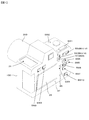
図1は、本発明の第一の実施形態による一眼レフ電子カメラの外観を例示する図である。図1において、カメラ本体100に対して着脱可能に構成される撮影レンズ鏡筒200が装着されている。カメラ本体100の上面に、メインスイッチSW1と、レリーズボタンSW2と、白黒液晶モニター31とを有する。電子カメラの背面に、左選択スイッチSW4と、右選択スイッチSW5と、上選択スイッチSW6と、下選択スイッチSW7と、確定スイッチSW8と、コマンドダイヤル53と、動画切替レバー55と、動画開始ボタン57と、カラー液晶モニター29とを有する。
Hereinafter, embodiments for carrying out the present invention will be described with reference to the drawings.
(First embodiment)
FIG. 1 is a diagram illustrating the external appearance of a single-lens reflex electronic camera according to the first embodiment of the present invention. In FIG. 1, a
電子カメラは、動画撮影を行うか否か、通常(効果付加なし)の動画撮影をするか、あるいは効果付加動画撮影をするかを、切替レバー55の設定状態に応じて決定する。「効果付加」とは、被写体を際立たせる効果を動画像に付加することをいう。「効果付加動画撮影」とは、動画開始および動画終了時における撮影画像を暈かすことにより、被写体を際立たせる効果を付加する動画撮影のことをいう。本実施形態の特徴である効果付加動画撮影の詳細については後述する。
The electronic camera determines whether to perform moving image shooting, whether to perform normal (no effect added) moving image shooting, or effect added moving image shooting according to the setting state of the
たとえば、切替レバー55が白丸ポジションに切替えられている場合の電子カメラは動画撮影を行わない。また、切替レバー55が黒丸ポジションに切替えられている場合の電子カメラは、動画開始ボタン57の押下操作に応じて通常動画撮影を開始し、再び動画開始ボタン57が押下操作されると通常動画撮影を終了する。
For example, the electronic camera when the switching
さらにまた、切替レバー55が斜線つき丸ポジションに切替えられている場合の電子カメラは、動画開始ボタン57の押下操作に応じて効果付加動画撮影を開始し、再び動画開始ボタン57が押下操作されると効果付加動画撮影を終了する。
Furthermore, the electronic camera in the case where the switching
図2は、上述した電子カメラの構成を説明するブロック図である。電子カメラは、マイクロコンピュータ101によって制御される。メインスイッチSW1は、電子カメラの電源オン/オフをそれぞれ指示する操作信号を出力する。レリーズスイッチ(SW2)は、レリーズボタンSW2の押下操作に連動して静止画撮影開始を指示する信号を出力する。
FIG. 2 is a block diagram illustrating the configuration of the electronic camera described above. The electronic camera is controlled by the
モードスイッチSW3は、電子カメラの動作モード、すなわち、撮影モードおよび再生モード等を切替えるための操作信号をそれぞれ出力する。左選択スイッチSW4、右選択スイッチSW5、上選択スイッチSW6、および下選択スイッチSW7は、それぞれ選択方向を示す操作信号を出力する。確定スイッチSW8は、操作確定を示す操作信号を出力する。 The mode switch SW3 outputs an operation signal for switching the operation mode of the electronic camera, that is, the photographing mode and the reproduction mode. The left selection switch SW4, the right selection switch SW5, the upper selection switch SW6, and the lower selection switch SW7 each output an operation signal indicating a selection direction. The confirmation switch SW8 outputs an operation signal indicating operation confirmation.
取消しスイッチSW9は、操作取消しを示す操作信号を出力する。削除スイッチ10は、記録済み画像ファイルの削除を指示する操作信号を出力する。スイッチSW11およびスイッチSW12は、コマンドダイヤル53の回転操作に応じて操作信号を出力する。
The cancel switch SW9 outputs an operation signal indicating operation cancellation. The deletion switch 10 outputs an operation signal instructing deletion of the recorded image file. The switch SW11 and the switch SW12 output an operation signal according to the rotation operation of the
スイッチSW13およびスイッチSW14は、上述した切替レバー55の切替操作に応じて操作信号を出力する。切替レバー55が白丸ポジションに切替えられると、スイッチSW13およびスイッチSW14はともにオフ操作信号を出力する。切替レバー55が黒丸ポジションに切替えられると、スイッチSW13のみがオン操作信号を出力する。切替レバー55が斜線丸ポジションに切替えられると、スイッチSW14のみがオン操作信号を出力する。スイッチSW15は、動画開始ボタン57の押下操作に連動して操作信号を指示する信号を出力する。
The switch SW13 and the switch SW14 output an operation signal according to the switching operation of the switching
レンズ鏡筒200はレンズ鏡筒内CPU(不図示)を含み、マイクロコンピュータ101との間で通信を行う。レンズ鏡筒内CPUは、マイクロコンピュータ101からの指示に応じてフォーカス駆動装置205および絞り駆動装置203を駆動制御し、撮影光学系201のフォーカス調節レンズ(不図示)を光軸方向に進退移動させたり、絞り(不図示)の口径を制御する。撮像素子11は、撮影光学系201によって撮像面上に結像されている被写体像を撮像し、被写体像の明るさに応じた光電変換信号を出力する。
The
本実施形態では、一眼レフ電子カメラのミラー(不図示)がダウン状態の場合に後述するAF素子15を用いて焦点検出処理を行う一方、該ミラーがアップ状態の場合には撮像素子11からの出力信号に基づいて焦点検出処理を行う。
In the present embodiment, when a mirror (not shown) of a single-lens reflex electronic camera is in a down state, focus detection processing is performed using an
コントラストAF処理回路13は、撮像素子11の所定画素からの出力信号(画素データ)を用いてコントラストを検出する公知のコントラスト検出方式の焦点検出処理を行う。具体的には、上記フォーカス調節レンズを進退移動させながら、画像のコントラストが最大になるレンズ位置を探し、該レンズ位置へフォーカス調節レンズを移動させることによってフォーカス調節(焦点位置の調節)を行う。
The contrast
AF素子15は、公知の瞳分割方式の焦点検出処理において用いるイメージセンサを含む。位相差AF処理回路14は、AF素子15からの出力信号に基づいて位相差検出演算処理(相関処理、位相差検出処理)を施すことにより、撮影光学系201の異なる領域を通過した一対の焦点検出用光束によって得られる一対の像の像ズレ量を検出する。さらに、像ズレ量に所定の変換係数を乗ずることにより、予定焦点面に対する現在の結像面の偏差(デフォーカス量)を算出する。そして、該デフォーカス量に応じて上記フォーカス調節レンズの移動方向および移動量を演算する。位相差AF処理回路14は、デフォーカス量を解消させるレンズ位置へ向けてフォーカス調節レンズを移動させることにより、フォーカス調節(焦点位置の調節)を行う。
The
測光装置21は、撮影光学系210を通過した被写体光を受光して測光演算を行う。ドライバ回路102は、マイクロコンピュータ101からの指令に応じてメカニカルシャッター23を駆動する。ドライバ回路103は、マイクロコンピュータ101からの指令に応じてミラー機構25を駆動する。ミラー機構25は、ミラー(不図示)をアップ駆動またはダウン駆動する。
The
ドライバ回路104は、マイクロコンピュータ101からの指令に応じてAF測距エリア照射装置27を駆動する。AF測距エリア照射装置27は、焦点検出処理時に測距補助光を発して被写体を照明する。
The
表示制御部28は、マイクロコンピュータ101からの指令によりカラー液晶モニター29に対する駆動信号を生成する。カラー液晶モニター29は、画像や操作メニューなどを表示する。表示制御部30は、マイクロコンピュータ101からの指令により白黒液晶モニター31に対する駆動信号を生成する。白黒液晶モニター31は、コマ数や撮影条件などの撮影情報を表示する。
The
外部インタフェース33は、電子カメラ内のデータをパソコンや別の電子カメラなどの外部機器へ出力(送信)したり、外部機器からのデータを入力(受信)したりするインターフェース回路である。外部インタフェース113の例として、RS232C、USB、IEEE1394などがある。
The
メモリカード35は、カードコネクター34を介してカメラ本体100に着脱される記録媒体である。メモリカード35には画像データや音声データが記録される。
The
ゲイン制御部37は、マイクロコンピュータ101からの指令により、動画像を記録する際にフレーム間で被写体輝度が所定値以上変化しないように、取得された画像の輝度に応じてゲイン制御を行う。具体的には、暗過ぎる画像にはゲインをかけて明るく補正し、明る過ぎる画像にはゲインをかけずに明るさを抑える補正を行う。
The
画像ボカシ処理部39は、マイクロコンピュータ101からの指令により、電子的に(すなわち画像処理によって)画像にボカシを付加するボカシ処理を行う。静止画像に対してボカシを付加する際に、付加するボカシ量を加減することが可能である。動画像に対してボカシを付加する際は、連続するフレーム間で付加するボカシ量を段階的に変化させることにより、動画再生時に画像が次第にぼけていく効果や、動画再生時に画像のボカシがだんだん少なくなって次第にはっきりする効果を有する動画像を生成する。ボカシを付加した動画像を生成する場合、元の動画像そのものにボカシを付加する場合と、元の動画像から切出した画像の複製を生成し、該複製画像にボカシを付加する場合とがある。
The image
動画編集処理部40は、画像ボカシ処理部39がボカシ量を段階的に変化させた複数フレームの画像を生成した場合に、元の動画像と連続するように該複数フレームの画像を元の動画像に入れ込んで動画像データを合成する。画像ボカシ処理部39および動画編集処理部40はそれぞれ、効果付加動画撮影時であって、電子的にボカシを付加する場合に上記処理を行う。
When the image
画像記憶メモリ41は、上述したボカシ処理や動画像合成処理、その他後述する圧縮/伸張処理の際に一時的に画像データを格納する。圧縮/伸長回路42は、所定の方式で画像データを圧縮処理したり、圧縮された画像データを伸長処理したりする。メモリ43は、マイクロコンピュータ101の作業領域として利用される。タイマー44は、マイクロコンピュータ101によって指定された時間を計時し、タイムアップ信号を出力する。
The
電子ブザー45は、マイクロコンピュータ101からの指令により、ビープ音を発生させる。スピーカー46は、マイクロコンピュータ101からの指令により、音声信号に基づいて音声を再生する。内蔵マイク47は、集音した音声を電気信号に変換する。電池49は、電子カメラ内の各部に電力を供給する。
The
本実施の形態は、上記電子カメラが行う効果付加動画撮影に特徴を有するので、以下の説明は効果付加動画撮影を中心に行う。第一の実施形態では、取得済みの元画像(または切出し画像の複製)に対して電子的にボカシを付加するのではなく、フォーカス調節レンズを移動させる(すなわち、フォーカス調節状態を変える)ことによって、ボカシを有する画像を取得する。 Since the present embodiment is characterized by effect-added moving image shooting performed by the electronic camera, the following description will be focused on effect-added moving image shooting. In the first embodiment, the focus adjustment lens is moved (that is, the focus adjustment state is changed) instead of electronically adding blur to the acquired original image (or a copy of the cut-out image). , Get an image with blur.
フォーカス調節状態を変えることによってボカシを有する画像を取得する場合は、次の2パターンがある。第1パターンは、フォーカス調節レンズを至近側(最短撮影距離にピントが合うレンズ位置)から被写体側(主要被写体にピントが合うレンズ位置)へ移動させることによって主要被写体像を次第にはっきりさせ、フォーカス調節レンズを被写体側(主要被写体にピントが合うレンズ位置)から至近側(最短撮影距離にピントが合うレンズ位置)へ移動させることによって主要被写体像を次第にぼかすパターンである。 When acquiring an image having blur by changing the focus adjustment state, there are the following two patterns. In the first pattern, the main subject image is gradually clarified by moving the focus adjustment lens from the closest side (lens position that focuses on the shortest shooting distance) to the subject side (lens position that focuses on the main subject). This is a pattern that gradually blurs the main subject image by moving the lens from the subject side (lens position where the main subject is in focus) to the closest side (lens position where the shortest shooting distance is in focus).
図3は、フォーカス調節レンズが至近側に位置する場合の画像を例示する図であり、図4は、フォーカス調節レンズが被写体側に位置する場合の画像を例示する図である。図3では電子カメラに近い窓枠がはっきりする一方で人物がぼけ、図4では人物がはっきりする一方で窓枠がぼける。 FIG. 3 is a diagram illustrating an image when the focus adjustment lens is positioned on the close side, and FIG. 4 is a diagram illustrating an image when the focus adjustment lens is positioned on the subject side. In FIG. 3, the window frame close to the electronic camera is clear while the person is blurred. In FIG. 4, the person is clear and the window frame is blurred.
第2パターンは、フォーカス調節レンズを無限遠側(遠方被写体にピントが合うレンズ位置)から被写体側(主要被写体にピントが合うレンズ位置)へ移動させることによって画像を次第にはっきりさせ、フォーカス調節レンズを被写体側(主要被写体にピントが合うレンズ位置)から無限遠側(遠方被写体にピントが合うレンズ位置)へ移動させることによって画像を次第に暈かすパターンである。 The second pattern makes the image gradually clearer by moving the focus adjustment lens from the infinity side (lens position where the far subject is in focus) to the subject side (lens position where the main subject is in focus). The pattern gradually blurs the image by moving from the subject side (lens position where the main subject is in focus) to the infinity side (lens position where the far subject is in focus).
図5は、フォーカス調節レンズが無限遠側に位置する場合の画像を例示する図である。図5では電子カメラから遠い木がはっきりする一方で人物が暈ける。図4では人物がはっきりする一方で遠方の木が暈ける。 FIG. 5 is a diagram illustrating an image when the focus adjustment lens is located on the infinity side. In FIG. 5, a tree far away from the electronic camera is clearly seen, but a person can grow. In FIG. 4, a person is clear, but a distant tree grows.
<動画設定とメニュー設定>
フォーカス調節状態を変えることによってボカシを有する画像を取得するために行われるメニュー設定操作について、図6〜図9に例示する操作画面を参照して説明する。図6は、カラー液晶モニター29に表示される「総合メニュー」画面を例示する図である。マイクロコンピュータ101は、モードスイッチSW3から操作信号が入力された場合に、メニューモード処理を起動して「総合メニュー」画面を表示させる。
<Video settings and menu settings>
A menu setting operation performed to acquire an image having blur by changing the focus adjustment state will be described with reference to the operation screens illustrated in FIGS. FIG. 6 is a diagram illustrating a “general menu” screen displayed on the color
マイクロコンピュータ101は、上選択スイッチSW6、または下選択スイッチSW7からの操作信号に応じて選択項目を上下に変更し、「撮影」項目を選択している状態で確定スイッチSW8から操作信号が入力されると、「総合メニュー」画面に代えて「撮影メニュー」画面を表示させる。図7は、カラー液晶モニター29に表示される「撮影メニュー」画面を例示する図である。
The
マイクロコンピュータ101は、上選択スイッチSW6、または下選択スイッチSW7からの操作信号に応じて選択項目を上下に変更し、「動画記録時の効果」項目を選択している状態で確定スイッチSW8から操作信号が入力されると、「撮影メニュー」画面に代えて「動画記録時の効果」画面を表示させる。図8は、カラー液晶モニター29に表示される「動画記録時の効果」画面を例示する図である。
The
マイクロコンピュータ101は、上選択スイッチSW6、または下選択スイッチSW7からの操作信号に応じて選択項目を上下に変更し、「この効果をつける」項目を選択している状態で確定スイッチSW8から操作信号が入力されると、「動画記録時の効果」画面に代えて図9に例示する設定画面を表示させる。図9は、カラー液晶モニター29に表示される効果設定画面を例示する図である。
The
マイクロコンピュータ101は、図9において、上選択スイッチSW6、または下選択スイッチSW7からの操作信号に応じて選択項目を上下に変更する。そして、「効果の種類」の項目を選択している状態で、右選択スイッチSW5から操作信号が入力されると、「効果の種類」の中から4つの内容の選択操作を受け付ける。「至近から被写体へ、被写体から至近へ」は、上述した第1パターンに相当する。「無限遠から被写体へ、被写体から無限遠へ」は、上述した第2パターンに相当する。
In FIG. 9, the
「被写体深度変化」は、フォーカス調節状態を変えることによってボカシを得るのではなく、絞り口径を変える(すなわち、被写界深度を変える)ことによって、ボカシを有する画像を取得するものである。「被写体深度変化」の詳細は、後述する第二の実施形態において説明する。 The “subject depth change” is to acquire an image having blur by changing the aperture diameter (that is, changing the depth of field) instead of obtaining blur by changing the focus adjustment state. Details of “subject depth change” will be described in a second embodiment to be described later.
「単純ボカシ」は、取得した画像に対して電子的にボカシを付加するものである。「単純ボカシ」は、上述した画像ボカシ処理部39および動画編集処理部40によって行う。「単純ボカシ」については後述する第三の実施形態において説明する。
“Simple blur” is to add blur to an acquired image electronically. The “simple blur” is performed by the image
マイクロコンピュータ101は、上選択スイッチSW6、または下選択スイッチSW7からの操作信号に応じて選択項目を上下に変更する。左選択スイッチSW4から操作信号が入力されると、その時点で選択している項目に決定し、再び「効果の種類」の項目を選択している状態(図9)に戻る。
The
マイクロコンピュータ101は、「効果をつける時間」の項目を選択している状態で、右選択スイッチSW5から操作信号が入力されると、「効果をつける時間」の中から2つの内容の選択操作を受け付ける。「1.5秒間」は、動画再生の中でボカシの付加時間を1.5秒にセットするものである。「3秒間」は、ボカシの付加時間を3秒間にセットするものである。なお、1.5秒間および3秒間は例示したものであり、これら以外の時間をセットするようにしてもかまわない。
When the
マイクロコンピュータ101は、「効果時の音声記録」の項目を選択している状態で、右選択スイッチSW5から操作信号が入力されると、「効果時の音声記録」の中から3つの内容の選択操作を受け付ける。「音声記録も連動させる」は、「効果をつける時間」の間に録音レベルを変化させるものである。ボカシ量およびボカシの付加時間に連動させて、録音レベルを絞った状態から通常レベルまで次第に上げ、録音レベルを通常レベルから次第に下げて絞る。
When the
「音声記録は一定」は、「効果をつける時間」の録音レベルを一定に保つものである。ボカシを付加する間も、通常レベルで録音する。「音声記録なし」は、「効果をつける時間」の録音レベルを絞って無音にするものである。 “Voice recording is constant” is to keep the recording level of “time to apply effect” constant. While adding blur, record at the normal level. “No voice recording” is to silence the recording level of “time to apply effect”.
マイクロコンピュータ101は、「設定終了」項目を選択している状態で確定スイッチSW8から操作信号が入力されると、メニューモード処理を終了する。
When the
(i)第1パターンによる効果付加動画撮影
マイクロコンピュータ101は、上記第1パターン「至近から被写体へ、被写体から至近へ」が設定されており、かつ切替レバー55が斜線つき丸ポジションに切替えられている場合に、第1パターンの効果付加動画撮影を行う。
(i) Effect-added moving image shooting using the first pattern The
−フォーカスイン処理−
マイクロコンピュータ101は、動画開始ボタン57が押下操作されると、至近側にピントが合った状態(図3)から所定時間t(tは「効果をつける時間」に相当)をかけて次第に主要被写体にピントが合う状態(図4)へフォーカス調節レンズを移動させ、そこから通常の動画撮影を続行する。音声記録については、「効果時の音声記録」に関して選択されている項目の内容に従う。
-Focus-in processing-
When the moving
−フォーカスアウト処理−
マイクロコンピュータ101は、動画撮影中に再び動画開始ボタン57が押下操作されると、主要被写体にピントが合った状態(図4)から所定時間t(tは「効果をつける時間」に相当)をかけて次第に至近側にピントが合う状態(図3)へフォーカス調節レンズを移動させ、動画撮影を終了する。音声記録については、「効果時の音声記録」に関して選択されている項目の内容に従う。
-Focus-out processing-
When the moving
(ii)第2パターンによる効果付加動画撮影
マイクロコンピュータ101は、上記第1パターン「無限遠から被写体へ、被写体から無限遠へ」が設定されており、かつ切替レバー55が斜線つき丸ポジションに切替えられている場合に、第2パターンの効果付加動画撮影を行う。
(ii) Effect-added moving image shooting using the second pattern The
−フォーカスイン処理−
マイクロコンピュータ101は、動画開始ボタン57が押下操作されると、無限遠側にピントが合った状態(図5)から所定時間t(tは「効果をつける時間」に相当)をかけて次第に主要被写体にピントが合う状態(図4)へフォーカス調節レンズを移動させ、そこから通常の動画撮影を続行する。音声記録については、「効果時の音声記録」に関して選択されている項目の内容に従う。
-Focus-in processing-
When the moving
−フォーカスアウト処理−
マイクロコンピュータ101は、動画撮影中に再び動画開始ボタン57が押下操作されると、主要被写体にピントが合った状態(図4)から所定時間t(tは「効果をつける時間」に相当)をかけて次第に無限遠側にピントが合う状態(図5)へフォーカス調節レンズを移動させ、動画撮影を終了する。音声記録については、「効果時の音声記録」に関して選択されている項目の内容に従う。
-Focus-out processing-
When the moving
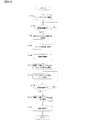
マイクロコンピュータ101が第1パターンによる効果付加動画撮影時に実行する制御処理の流れについて、図10に例示するフローチャートを参照して説明する。切替レバー55が斜線つき丸ポジションに切替えられると、マイクロコンピュータ101は、カラー液晶モニター29にライブビュー画像を表示させて図10による処理を起動させる。ライブビュー画像は、撮像素子11によって所定のフレームレートで撮像された画素データに基づいて再生されるモニタ用の画像である。
The flow of control processing executed by the
図10のステップS101において、マイクロコンピュータ101は、コントラスト検出方式の焦点検出処理を開始させてステップS103へ進む。これにより、ライブビュー画像に基づくコントラストを最大にするように主要被写体にピントを合わせ続ける。ステップS103において、マイクロコンピュータ101は、動画記録の開始が指示されたか否かを判定する。マイクロコンピュータ101は、動画開始ボタン57が押下操作されるとステップS103を肯定判定してステップS105へ進み、動画開始ボタン57が押下操作されない場合にはステップS103を否定判定して当該判定処理を繰り返す。
In step S101 of FIG. 10, the
ステップS105において、マイクロコンピュータ101は、現在のフォーカス制御位置(フォーカス調節レンズの位置)をメモリ43に一時記憶してステップS107へ進む。ステップS107において、マイクロコンピュータ101はレンズ鏡筒200内のCPUへ指示を送り、フォーカス調節レンズを至近端位置へ移動させてステップS109へ進む。これ以降、後述するステップS113までピント合わせを中断する。
In step S105, the
ステップS109において、マイクロコンピュータ101は、動画記録を開始してステップS111へ進む。これにより、所定のフレームレート(たとえば、60フレーム/秒)で画像の取得を開始する(録画開始)。なお、「音声記録なし」が選択されている場合を除いて音声の取得も開始する(録音開始)。ステップS111において、マイクロコンピュータ101はレンズ鏡筒200内のCPUへ指示を送り、時間tの間にフォーカス調節レンズをメモリ43に一時記憶した位置まで移動させてステップS113へ進む。時間tは「効果をつける時間」に相当する。なお、「音声記録も連動させる」が選択されている場合は、時間tの間に録音レベルを無音から通常レベルまで変化するように音声ゲインを制御する。
In step S109, the
ステップS113において、マイクロコンピュータ101は、コントラスト検出方式の焦点検出処理を再開させてステップS115へ進む。なお、マイクロコンピュータ101はゲイン制御部37へ指示を送り、動画記録するフレーム間で被写体輝度が所定値以上変化しないように、取得された画像の輝度に応じて適宜ゲイン制御を行わせる。
In step S113, the
ステップS115において、マイクロコンピュータ101は、動画記録の終了が指示されたか否かを判定する。マイクロコンピュータ101は、動画開始ボタン57が押下操作されるとステップS115を肯定判定してステップS117へ進み、動画開始ボタン57が押下操作されない場合にはステップS115を否定判定してステップS113へ戻る。ステップS113へ戻る場合は、ピント合わせおよび輝度制御をしながら画像の取得を継続する。
In step S115, the
ステップS117において、マイクロコンピュータ101はレンズ鏡筒200内のCPUへ指示を送り、時間tの間にフォーカス調節レンズを至近端位置まで移動させてステップS119へ進む。時間tは「効果をつける時間」に相当する。なお、「音声記録も連動させる」が選択されている場合は、時間tの間に録音レベルを通常レベルから無音まで変化するように音声ゲインを制御する。
In step S117, the
ステップS119において、マイクロコンピュータ101は動画記録を終了する。すなわち、取得した動画像を格納する所定の動画像ファイル、および音声データを格納する所定の音声ファイルをそれぞれ生成し、メモリカード35に記録させて図10による処理を終了する。
In step S119, the
マイクロコンピュータ101が第2パターンによる効果付加動画撮影時に実行する場合は、図10のステップS107およびS117において、それぞれ以下のように処理を行う。すなわち、ステップS107において、マイクロコンピュータ101はレンズ鏡筒200内のCPUへ指示を送り、フォーカス調節レンズを無限遠端位置へ移動させてステップS109へ進む。これ以降、後述するステップS113までピント合わせを中断する。
When the
ステップS117において、マイクロコンピュータ101はレンズ鏡筒200内のCPUへ指示を送り、時間tの間にフォーカス調節レンズを無限遠端位置まで移動させてステップS119へ進む。時間tは「効果をつける時間」に相当する。なお、「音声記録も連動させる」が選択されている場合は、時間tの間に録音レベルを通常レベルから無音まで変化するように音声ゲインを制御する。
In step S117, the
以上説明した第一の実施形態によれば、次の作用効果が得られる。
(1)電子カメラは、撮影光学系201を通した被写体像を所定のフレームレートで取得する撮像素子11と、撮像素子11で取得された複数フレームの画像を記録媒体35に記録するマイクロコンピュータ101と、記録開始指示に応じて記録用画像の取得を開始し、記録終了指示に応じて記録用画像の取得を終了するように撮像素子11を制御するマイクロコンピュータ101と、記録する画像の先頭部に次第に像ぼけが変化する複数フレームの画像を含める、および記録する画像の末尾部に次第に像ぼけが変化する複数フレームの画像を含める、の少なくとも一方を行うマイクロコンピュータ101とを備えるようにした。これにより、動画記録の開始時や終了時に自動的にフォーカスイン(またはアウト)の効果を有する動画像が得られる。
According to the first embodiment described above, the following operational effects can be obtained.
(1) The electronic camera captures the subject image that has passed through the photographing
たとえば、動画像の再生時には、先頭部のフォーカスイン効果によって再生動画像を鑑賞する者の目を主要被写体に向けさせることができる。また、末尾部のフォーカスアウト効果によって、鑑賞者に再生終了を観念させることができる。 For example, when a moving image is reproduced, the eyes of the person viewing the reproduced moving image can be directed to the main subject by the focus-in effect at the top. In addition, it is possible to make the viewer think of the end of playback by the focus-out effect at the end.
(2)電子カメラはさらに、撮影光学系201の焦点位置を調節するコントラストAF処理回路13を備え、マイクロコンピュータ101は、記録開始指示に応じて、焦点調節状態を一旦変更してから該変更前の焦点調節状態へ戻すようにコントラストAF処理回路13へ指示する一方、変更前の焦点調節状態へ戻る前に撮像素子11に記録用画像の取得を開始させ、記録終了指示に応じて、焦点調節状態を変更するようにコントラストAF処理回路13段へ指示する一方、当該変更後に撮像素子11に記録用画像の取得を終了させるようにした。これにより、動画記録の開始時には次第にピントが合う複数フレームの画像が得られ、動画記録の終了時には次第にピントが外れる複数フレームの画像が自動的に得られる。
(2) The electronic camera further includes a contrast
(3)コントラストAF処理回路13は、記録開始指示の前に主要被写体に合焦するように焦点位置を調節するようにしたので、あらかじめピントが合う位置をつかんでおける。
(3) Since the contrast
(4)一眼レフタイプのカメラでは、コンパクトカメラの場合に比べて主要被写体の背景にきれいな像ぼけが得られる。この像ぼけを活かしてフォーカスイン(またはアウト)を行うことで、コンパクトカメラに比べて有利なフォーカスイン(またはアウト)の効果が得られる。 (4) With a single-lens reflex type camera, a clear image blur can be obtained in the background of the main subject as compared with a compact camera. By performing focus-in (or out) utilizing this image blur, an advantageous focus-in (or out) effect can be obtained compared to a compact camera.
(変形例1)
第一の実施形態では、フォーカスイン処理においてピントを外す準備動作が終ってから(すなわち、ステップS105およびS107の後)、ステップS109において動画記録を開始したが、ステップS105およびS107の前から動画記録を開始させてもよい。
(Modification 1)
In the first embodiment, the moving image recording is started in step S109 after the preparatory operation for defocusing in the focus-in process (that is, after steps S105 and S107), but the moving image recording is performed before steps S105 and S107. May be started.
(変形例2)
第一の実施形態では、ピント合わせした状態(ステップS101の後)で動画記録の開始指示を受け付ける(ステップS103)ようにしたが、動画記録の開始指示を受け付けてから(ステップS103を肯定判定)ピント合わせを行い、ピント合わせ後のフォーカス調節レンズを至近端位置へ移動する(ステップS107)ように構成してもよい。
(Modification 2)
In the first embodiment, the moving image recording start instruction is accepted in the focused state (after step S101) (step S103). However, after the moving image recording start instruction is accepted (step S103 is positively determined). Focusing may be performed, and the focus adjustment lens after focusing may be moved to the closest end position (step S107).
(変形例3)
第一の実施形態では、フォーカスイン処理においてフォーカス調節レンズを至近端位置へ移動(第1パターンの場合)、または無限遠端位置へ移動(第2パターンの場合)するようにした。この場合、フォーカス調節レンズの位置を少なくとも主要被写体からピントを外す位置へ移動させれば十分であり、必ずしも至近端位置(または無限遠端位置)まで移動させなくてもよい。たとえば、撮影画面内の複数の測距ポイントにおいて焦点調節状態を検出する多点AF測距方式の場合には、主要被写体と異なる他の被写体にピントが合う位置へフォーカス調節レンズを移動させるように構成してもよい。
(Modification 3)
In the first embodiment, the focus adjustment lens is moved to the closest end position (in the case of the first pattern) or moved to the infinite end position (in the case of the second pattern) in the focus-in process. In this case, it is sufficient to move the position of the focus adjustment lens to at least a position where the main subject is out of focus, and it is not always necessary to move the focus adjustment lens to the closest end position (or infinity end position). For example, in the case of a multi-point AF distance detection method that detects the focus adjustment state at a plurality of distance measurement points in the shooting screen, the focus adjustment lens is moved to a position where another subject different from the main subject is in focus. It may be configured.
(第二の実施形態)
第二の実施形態は、上述した「被写体深度変化」に相当し、フォーカス調節状態を変えることによってボカシを有する画像を取得するのではなく、絞り口径を変える(すなわち、被写界深度を変える)ことによって、ボカシを有する画像を取得する。
(Second embodiment)
The second embodiment corresponds to the “subject depth change” described above, and does not acquire an image having blur by changing the focus adjustment state, but changes the aperture diameter (that is, changes the depth of field). As a result, an image having blur is obtained.
マイクロコンピュータ101は、「被写界深度変化」が設定されており、かつ切替レバー55が斜線つき丸ポジションに切替えられている場合に、第二の実施形態の効果付加動画撮影を行う。
The
−フォーカスイン処理−
マイクロコンピュータ101は、動画開始ボタン57が押下操作されると、最絞り込みによって至近から無限まで広い範囲でピントの合った状態(図11)から所定時間t(tは「効果をつける時間」に相当)をかけて次第に絞りを開き、主要被写体にピントが合う状態(図12)へ被写界深度を変化させてから、通常の動画撮影を続行する。音声記録については、「効果時の音声記録」に関して選択されている項目の内容に従う。
-Focus-in processing-
When the moving
図11は、被写界深度が深い場合の画像を例示する図であり、図12は、被写界深度が浅い場合の画像を例示する図である。図11では、人物を含めて電子カメラに近い窓枠から遠方の木までがはっきりする。図4では人物がはっきりするだけで電子カメラに近い窓枠も遠方の木もぼける。 FIG. 11 is a diagram illustrating an image when the depth of field is deep, and FIG. 12 is a diagram illustrating an image when the depth of field is shallow. In FIG. 11, the window frame close to the electronic camera including the person to the distant tree is clear. In FIG. 4, the window frame near the electronic camera and the distant tree are blurred only by making the person clear.
−フォーカスアウト処理−
マイクロコンピュータ101は、動画撮影中に再び動画開始ボタン57が押下操作されると、主要被写体にピントが合う状態(図12)から所定時間t(tは「効果をつける時間」に相当)をかけて次第に絞り口径を狭くし、広い範囲でピントの合った状態(図11)へ被写界深度を変化させてから、動画撮影を終了する。音声記録については、「効果時の音声記録」に関して選択されている項目の内容に従う。
-Focus-out processing-
When the moving
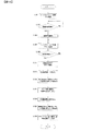
マイクロコンピュータ101が第二の実施形態による効果付加動画撮影時に実行する制御処理の流れについて、図13に例示するフローチャートを参照して説明する。切替レバー55が斜線つき丸ポジションに切替えられると、マイクロコンピュータ101は、カラー液晶モニター29にライブビュー画像を表示させて図13による処理を起動させる。
A flow of control processing executed by the
図13のステップS201において、マイクロコンピュータ101は、コントラスト検出方式の焦点検出処理を開始させてステップS203へ進む。これにより、ライブビュー画像に基づくコントラストを最大にするように主要被写体にピントを合わせ続ける。ステップS203において、マイクロコンピュータ101は、動画記録の開始が指示されたか否かを判定する。マイクロコンピュータ101は、動画開始ボタン57が押下操作されるとステップS203を肯定判定してステップS205へ進み、動画開始ボタン57が押下操作されない場合にはステップS203を否定判定して当該判定処理を繰り返す。
In step S201 of FIG. 13, the
ステップS205において、マイクロコンピュータ101は、現在の絞り値をメモリ43に一時記憶してステップS207へ進む。現在の絞り値は、たとえば、測光装置21による測光演算結果に基づいて決定した制御絞り値である。ステップS207において、マイクロコンピュータ101はレンズ鏡筒200内のCPUへ指示を送り、絞り駆動装置205により絞りを最小口径(最絞り込み)状態へ移動させてステップS209へ進む。この際、マイクロコンピュータ101はゲイン制御部37へ指示を送り、絞り値を変化させても被写体輝度が所定値以上変化しないように、取得された画像の輝度に応じて適宜ゲイン制御を行わせる。なお、後述するステップS213までピント合わせを中断する。
In step S205, the
ステップS209において、マイクロコンピュータ101は、動画記録を開始してステップS211へ進む。これにより、所定のフレームレート(たとえば、60フレーム/秒)で画像の取得を開始する(録画開始)。なお、「音声記録なし」が選択されている場合を除いて音声の取得も開始する(録音開始)。ステップS211において、マイクロコンピュータ101はレンズ鏡筒200内のCPUへ指示を送り、時間tの間にメモリ43に一時記憶した絞り値まで絞りを移動させてステップS213へ進む。時間tは「効果をつける時間」に相当する。マイクロコンピュータ101はゲイン制御部37へ指示を送り、絞り値を変化させても被写体輝度が所定値以上変化しないように、取得された画像の輝度に応じて適宜ゲイン制御させる。なお、「音声記録も連動させる」が選択されている場合は、時間tの間に録音レベルを無音から通常レベルまで変化するように音声ゲインを制御する。
In step S209, the
ステップS213において、マイクロコンピュータ101は、コントラスト検出方式の焦点検出処理を再開させてステップS215へ進む。マイクロコンピュータ101はゲイン制御部37へ指示を送り、動画記録するフレーム間で被写体輝度が所定値以上変化しないように、取得された画像の輝度に応じて適宜ゲイン制御を行わせる。
In step S213, the
ステップS215において、マイクロコンピュータ101は、動画記録の終了が指示されたか否かを判定する。マイクロコンピュータ101は、動画開始ボタン57が押下操作されるとステップS215を肯定判定してステップS217へ進み、動画開始ボタン57が押下操作されない場合にはステップS215を否定判定してステップS213へ戻る。ステップS213へ戻る場合は、ピント合わせおよび輝度制御をしながら画像の取得を継続する。
In step S215, the
ステップS217において、マイクロコンピュータ101はレンズ鏡筒200内のCPUへ指示を送り、時間tの間に絞りを最小口径(最絞り込み)状態へ移動させてステップS219へ進む。時間tは「効果をつける時間」に相当する。マイクロコンピュータ101はゲイン制御部37へ指示を送り、絞り値を変化させても被写体輝度が所定値以上変化しないように、取得された画像の輝度に応じて適宜ゲイン制御を行わせる。なお、「音声記録も連動させる」が選択されている場合は、時間tの間に録音レベルを通常レベルから無音まで変化するように音声ゲインを制御する。
In step S217, the
ステップS219において、マイクロコンピュータ101は動画記録を終了する。すなわち、取得した動画像を格納する所定の動画像ファイル、および音声データを格納する所定の音声ファイルをそれぞれ生成し、メモリカード35に記録させて図13による処理を終了する。
In step S219, the
以上説明した第二の実施形態によれば、次の作用効果が得られる。すなわち、電子カメラは、撮影光学系201の絞りを調節する絞り駆動装置203をさらに備え、マイクロコンピュータ101は、記録開始指示に応じて、絞り調節状態を一旦変更してから該変更前の絞り調節状態へ戻すように絞り駆動装置203へ指示する一方、変更前の絞り節状態へ戻る前に撮像素子11に記録用画像の取得を開始させ、記録終了指示に応じて、絞り調節状態を変更するように絞り駆動装置203へ指示する一方、当該変更後に撮像素子11に記録用画像の取得を終了させるようにした。これにより、動画記録の開始時には次第に被写界深度が変化する(たとえば浅くなる)ことで像ぼけが異なる複数フレームの画像が得られ、動画記録の終了時には次第に被写界深度が変化する(たとえば深くなる)ことで像ぼけが異なる複数フレームの画像が自動的に得られる。
According to the second embodiment described above, the following operational effects can be obtained. That is, the electronic camera further includes an
(変形例4)
上記第二の実勢形態では、ステップS207およびステップS217において、絞りを最小口径(最絞り込み)状態へ移動させるようにしたが、この代わりに、最大口径(絞りを最も開いた状態)へ移動させるようにしてもよい。
(Modification 4)
In the second actual form, in step S207 and step S217, the aperture is moved to the minimum aperture (maximum aperture) state. Instead, the aperture is moved to the maximum aperture (the aperture is in the most open state). It may be.
(第三の実施形態)
第三の実施形態は、上述した「単純ボカシ」に相当し、取得した画像に対して電子的にボカシを付加するものである。
(Third embodiment)
The third embodiment corresponds to the “simple blur” described above, and electronically adds blur to an acquired image.
マイクロコンピュータ101は、「単純ボカシ」が設定されており、かつ切替レバー55が斜線つき丸ポジションに切替えられている場合に、第三の実施形態の効果付加動画撮影を行う。
The
−フォーカスイン処理−
マイクロコンピュータ101は、第一の実施形態および第二の実施形態と異なり、動画開始ボタン57が押下操作されると、主要被写体にピントが合う状態(図14)で通常の動画撮影を開始する。動画撮影の終了後に、先頭コマの画像をN枚(再生時間が上記t「効果をつける時間」に相当する枚数)複製し、該複製した画像全体にそれぞれ段階的に異なるボカシを付加する。たとえば、複製したN枚のうち1枚目に最も大きなボカシを与え(図15)、段階的にボカシを減らし、複製したN枚目に最も小さなボカシを与える。
-Focus-in processing-
Unlike the first and second embodiments, when the moving
図14は、ボカシを付加する前の画像を例示する図であり、図15は、ボカシを付加した後の画像を例示する図である。図14では、人物がはっきりするだけで電子カメラに近い窓枠も遠方の木もぼける。図15では人物を含めて画像全体がさらにぼける。 FIG. 14 is a diagram illustrating an image before adding blur, and FIG. 15 is a diagram illustrating an image after adding blur. In FIG. 14, the window frame close to the electronic camera and the distant tree are blurred only by making the person clear. In FIG. 15, the entire image including the person is further blurred.
−フォーカスアウト処理−
マイクロコンピュータ101は、動画撮影中に再び動画開始ボタン57が押下操作されると、第一の実施形態および第二の実施形態と異なり、直ちに動画撮影を終了する。動画撮影の終了後に、最終コマの画像をN枚(再生時間が上記t「効果をつける時間」に相当する枚数)複製し、該複製した画像全体にそれぞれ段階的に異なるボカシを付加する。たとえば、複製したN枚のうち1枚目に最も小さなボカシを与え、段階的にボカシを増やし、複製したN枚目に最も大きなボカシを与える(図15)。
-Focus-out processing-
When the moving
マイクロコンピュータ101が第三の実施形態による効果付加動画撮影時に実行する制御処理の流れについて、図16に例示するフローチャートを参照して説明する。切替レバー55が斜線つき丸ポジションに切替えられると、マイクロコンピュータ101は、カラー液晶モニター29にライブビュー画像を表示させて図16による処理を起動させる。
A flow of control processing executed by the
図16のステップS301において、マイクロコンピュータ101は、コントラスト検出方式の焦点検出処理およびプリ録音を開始させてステップS303へ進む。これにより、ライブビュー画像に基づくコントラストを最大にするように主要被写体にピントを合わせ続けるとともに、「音声記録なし」が選択されている場合を除いてメモリ43に対して通常の録音レベルでプリ録音を行う。プリ録音は、動画開始ボタン57が押下操作される前の所定時間t(tは「効果をつける時間」に相当する)の音声を録音することをいう。プリ録音では、直近の時間tの音声データをメモリ43に保持し、それ以前の音声データは逐次メモリ43において上書き消去する。
In step S301 in FIG. 16, the
ステップS303において、マイクロコンピュータ101は、動画記録の開始が指示されたか否かを判定する。マイクロコンピュータ101は、動画開始ボタン57が押下操作されるとステップS303を肯定判定してステップS305へ進み、動画開始ボタン57が押下操作されない場合にはステップS303を否定判定して当該判定処理を繰り返す。
In step S303, the
ステップS305において、マイクロコンピュータ101は、動画記録を開始してステップS307へ進む。これにより、所定のフレームレート(たとえば、60フレーム/秒)で画像の取得を開始する(録画開始)。なお、「音声記録なし」が選択されている場合を除いてプリ録音から通常録音に切替えることにより、動画開始ボタン57が押下操作される直前の時間tおよび動画開始ボタン57が押下操作された後に取得した音声データを上書き消去しないようにする。
In step S305, the
ステップS307において、マイクロコンピュータ101はコントラスト検出方式の焦点検出処理を継続させてステップS309へ進む。マイクロコンピュータ101はゲイン制御部37へ指示を送り、動画記録するフレーム間で被写体輝度が所定値以上変化しないように、取得された画像の輝度に応じて適宜ゲイン制御を行わせる。
In step S307, the
ステップS309において、マイクロコンピュータ101は、動画記録の終了が指示されたか否かを判定する。マイクロコンピュータ101は、動画開始ボタン57が押下操作されるとステップS309を肯定判定してステップS311へ進み、動画開始ボタン57が押下操作されない場合にはステップS309を否定判定してステップS307へ戻る。ステップS307へ戻る場合は、ピント合わせおよび輝度制御をしながら画像の取得を継続する。
In step S309, the
ステップS311において、マイクロコンピュータ101は動画記録を終了するとともに、動画記録終了後も所定時間t(tは「効果をつける時間」に相当する)の音声取得を継続して(ポスト録音)ステップS313へ進む。
In step S311, the
ステップS313において、マイクロコンピュータ101は、メモリーカード35に記録された動画像を構成する画像のうち先頭コマの画像を切出してステップS315へ進む。ステップS315において、マイクロコンピュータ101は、切出し画像を上述したようにN枚複製し、画像ボカシ処理部39で公知の画像処理(たとえばフィルタ処理)によってN枚の複製画像に段階的に異なるボカシを付与させてステップS317へ進む。
In step S313, the
ステップS317において、マイクロコンピュータ101は動画編集処理部40へ指示を送り、N枚の画像をボカシが大きい順に配列して動画像として編集させる。そして、ステップS305から記録した動画像の先頭に編集した動画像を付加してステップS319へ進む。なお、「音声記録も連動させる」が選択されている場合は、プリ録音時間tの間に録音した音声レベルを無音から通常レベルまで次第に変化するように音声ゲインを制御する。
In step S317, the
ステップS319において、マイクロコンピュータ101は、メモリーカード35に記録された動画像を構成する画像のうち最終コマの画像を切出してステップS321へ進む。ステップS321において、マイクロコンピュータ101は、切出し画像を上述したようにN枚複製し、画像ボカシ処理部39で公知の画像処理(たとえばフィルタ処理)によってN枚の複製画像に段階的に異なるボカシを付与させてステップS323へ進む。
In step S319, the
ステップS323において、マイクロコンピュータ101は動画編集処理部40へ指示を送り、N枚の画像をボカシが小さい順に配列して動画像として編集させる。そして、ステップS305から記録した動画像の終端(末尾)に編集した動画像を付加する。なお、「音声記録も連動させる」が選択されている場合は、ポスト録音時間tの間に録音した音声レベルを通常レベルから無音まで次第に変化するように音声ゲインを制御する。
In step S323, the
マイクロコンピュータ101は、ボカシを段階的に付加した動画像を元の動画像の前後にそれぞれ付加し、該付加後の動画像を格納する動画像ファイルと、音声ゲイン制御後のプリ録音による音声データ、所定の録音データおよび音声ゲイン制御後のポスト録音による音声データとを格納する音声ファイルとを、それぞれ生成し、メモリカード35に記録させて図16による処理を終了する。
The
以上説明した第三の実施形態によれば、次の作用効果が得られる。すなわち、電子カメラは、画像を加工して該画像にぼかしを付加する画像ボカシ処理部39をさらに備え、マイクロコンピュータ101は、取得された複数フレームの画像の先頭フレームの画像を所定枚数複製し、該複製画像のそれぞれに対して次第に像ぼけが減少するように異なるぼかしを付加する、および取得された複数フレームの画像の末尾フレームの画像を所定枚数複製し、該複製画像のそれぞれに対して次第に像ぼけが増加するように異なるぼかしを付加する、の少なくとも一方を行うようにした。これにより、動画記録の開始時には次第に像ぼけが減少する複数フレームの画像が得られ、動画記録の終了時には次第に像ぼけが増加する複数フレームの画像が自動的に得られる。
According to the third embodiment described above, the following operational effects can be obtained. That is, the electronic camera further includes an image
以上の説明はあくまで一例であり、上記の実施形態の構成に何ら限定されるものではない。たとえば、フォーカスインおよびフォーカスアウトの両方を行わずとも、いずれか一方を行う構成でもよい。また、電子カメラは一眼レフタイプでなくてもよいのはいうまでもない。 The above description is merely an example, and is not limited to the configuration of the above embodiment. For example, a configuration in which either one of the focus in and the focus out is not performed may be used. Needless to say, the electronic camera may not be of a single-lens reflex type.
11…撮像素子
35…メモリカード
39…画像ボカシ処理部
101…マイクロコンピュータ
201…撮影光学系
203…絞り駆動装置
205…フォーカス駆動装置
SW15…動画開始/終了スイッチ
DESCRIPTION OF SYMBOLS 11 ... Image pick-up
Claims (6)
前記撮像手段で取得された複数フレームの画像を記録媒体に記録する記録手段と、
記録開始指示に応じて記録用画像の取得を開始し、記録終了指示に応じて記録用画像の取得を終了するように前記撮像手段を制御する撮像制御手段と、
記録する画像の先頭部に次第に像ぼけが変化する複数フレームの画像を含める、および記録する画像の末尾部に次第に像ぼけが変化する複数フレームの画像を含める、の少なくとも一方を行う効果付与手段と、
を備えることを特徴とする撮影機器。 Imaging means for acquiring a subject image through a photographing optical system at a predetermined frame rate;
Recording means for recording a plurality of frames of images acquired by the imaging means on a recording medium;
Imaging control means for controlling the imaging means to start acquisition of a recording image in response to a recording start instruction and end acquisition of a recording image in response to a recording end instruction;
An effect applying means for performing at least one of including a plurality of frames of images with gradually changing image blur at the beginning of the image to be recorded and including a plurality of frames with gradually changing image blur at the end of the image to be recorded; ,
An imaging device comprising:
前記撮影光学系の焦点位置を調節するフォーカス調節手段をさらに備え、
前記効果付与手段は、
前記記録開始指示に応じて、焦点調節状態を一旦変更してから該変更前の焦点調節状態へ戻すように前記フォーカス調節手段へ指示する一方、前記変更前の焦点調節状態へ戻る前に前記撮像手段に記録用画像の取得を開始させ、
前記記録終了指示に応じて、前記焦点調節状態を変更するように前記フォーカス調節手段へ指示する一方、当該変更後に前記撮像手段に記録用画像の取得を終了させる、
ことを特徴とする撮影機器。 The imaging device according to claim 1,
A focus adjusting means for adjusting a focal position of the photographing optical system;
The effect applying means is
In response to the recording start instruction, the focus adjustment unit is instructed to change the focus adjustment state once and then return to the focus adjustment state before the change, while the imaging before returning to the focus adjustment state before the change. To start the acquisition of the image for recording,
In response to the recording end instruction, the focus adjustment unit is instructed to change the focus adjustment state, and after the change, the imaging unit ends acquisition of the recording image.
An imaging device characterized by that.
前記撮影光学系の絞りを調節する絞り調節手段をさらに備え、
前記効果付与手段は、
前記記録開始指示に応じて、絞り調節状態を一旦変更してから該変更前の絞り調節状態へ戻すように前記絞り調節手段へ指示する一方、前記変更前の絞り節状態へ戻る前に前記撮像手段に記録用画像の取得を開始させ、
前記記録終了指示に応じて、前記絞り調節状態を変更するように前記絞り調節手段へ指示する一方、当該変更後に前記撮像手段に記録用画像の取得を終了させる、
ことを特徴とする撮影機器。 The imaging device according to claim 1,
A diaphragm adjusting means for adjusting the diaphragm of the photographing optical system is further provided,
The effect applying means is
In response to the recording start instruction, the aperture adjustment unit is instructed to change the aperture adjustment state once and then return to the aperture adjustment state before the change, while the imaging before returning to the aperture clause state before the change. To start the acquisition of the image for recording,
In response to the recording end instruction, the diaphragm adjustment unit is instructed to change the diaphragm adjustment state, and after the change, the imaging unit ends acquisition of the recording image.
An imaging device characterized by that.
前記フォーカス調節手段は、前記記録開始指示の前に主要被写体に合焦するように前記焦点位置を調節することを特徴とする撮影機器。 In the imaging device according to any one of claims 1 to 3,
The photographing apparatus according to claim 1, wherein the focus adjusting unit adjusts the focal position so that the main subject is focused before the recording start instruction.
前記フォーカス調節手段は、前記記録開始指示に応じて主要被写体に合焦するように前記焦点位置を調節し、
前記効果付与手段は、前記調節後の焦点調節状態を一旦変更してから該変更前の焦点調節状態へ戻すように前記フォーカス調節手段へ指示する一方、前記変更前の焦点調節状態へ戻る前から前記撮像手段に記録用画像の取得を開始させることを特徴とする撮影機器。 The imaging device according to claim 1 or 2,
The focus adjusting means adjusts the focal position so as to focus on a main subject according to the recording start instruction,
The effect applying means instructs the focus adjusting means to change the focus adjustment state after the adjustment once and then return to the focus adjustment state before the change, while before returning to the focus adjustment state before the change. An imaging apparatus, characterized in that the imaging means starts acquisition of a recording image.
画像を加工して該画像にぼかしを付加するぼかし付加手段をさらに備え、
前記効果付与手段は、
前記取得された複数フレームの画像の先頭フレームの画像を所定枚数複製し、該複製画像のそれぞれに対して次第に像ぼけが減少するように異なるぼかしを付加する、および前記取得された複数フレームの画像の末尾フレームの画像を所定枚数複製し、該複製画像のそれぞれに対して次第に像ぼけが増加するように異なるぼかしを付加する、の少なくとも一方を行う、
ことを特徴とする撮影機器。 The imaging device according to claim 1,
Further comprising blur adding means for processing the image and adding blur to the image;
The effect applying means is
Duplicating a predetermined number of images of the first frame of the acquired multiple-frame images, adding different blurs to each of the replicated images so as to gradually reduce image blur, and the acquired multiple-frame images Performing at least one of copying a predetermined number of images of the last frame of the image and adding different blurs to each of the copied images so that image blur gradually increases.
An imaging device characterized by that.
Priority Applications (1)
| Application Number | Priority Date | Filing Date | Title |
|---|---|---|---|
| JP2010285794A JP2012134810A (en) | 2010-12-22 | 2010-12-22 | Photographing apparatus |
Applications Claiming Priority (1)
| Application Number | Priority Date | Filing Date | Title |
|---|---|---|---|
| JP2010285794A JP2012134810A (en) | 2010-12-22 | 2010-12-22 | Photographing apparatus |
Publications (1)
| Publication Number | Publication Date |
|---|---|
| JP2012134810A true JP2012134810A (en) | 2012-07-12 |
Family
ID=46649862
Family Applications (1)
| Application Number | Title | Priority Date | Filing Date |
|---|---|---|---|
| JP2010285794A Pending JP2012134810A (en) | 2010-12-22 | 2010-12-22 | Photographing apparatus |
Country Status (1)
| Country | Link |
|---|---|
| JP (1) | JP2012134810A (en) |
Cited By (2)
| Publication number | Priority date | Publication date | Assignee | Title |
|---|---|---|---|---|
| JP2017038254A (en) * | 2015-08-11 | 2017-02-16 | キヤノン株式会社 | Imaging device, image processing apparatus, image processing method, and program |
| US10447919B2 (en) | 2017-03-14 | 2019-10-15 | Olympus Corporation | Imaging device, external device, imaging system, imaging method, operating method, and computer-readable recording medium |
Citations (8)
| Publication number | Priority date | Publication date | Assignee | Title |
|---|---|---|---|---|
| JPH024088A (en) * | 1988-06-20 | 1990-01-09 | Hitachi Ltd | Focus adjustor for video camera and the like |
| JPH0433478A (en) * | 1990-05-29 | 1992-02-04 | Matsushita Electric Ind Co Ltd | Image pickup device |
| JPH09186956A (en) * | 1995-12-28 | 1997-07-15 | Samsung Electron Co Ltd | Video camera incorporated with still camera |
| JP2005136754A (en) * | 2003-10-31 | 2005-05-26 | Matsushita Electric Ind Co Ltd | Imaging apparatus |
| JP2006135479A (en) * | 2004-11-04 | 2006-05-25 | Canon Inc | Imaging device |
| JP2007243928A (en) * | 2006-02-09 | 2007-09-20 | Nippon Hoso Kyokai <Nhk> | Gradation nd filter unit for television camera, nd adapter, and television camera |
| JP2008046225A (en) * | 2006-08-11 | 2008-02-28 | Canon Inc | Focus controller and imaging apparatus |
| JP2012095247A (en) * | 2010-10-29 | 2012-05-17 | Pentax Ricoh Imaging Co Ltd | Digital camera, imaging method of digital camera, and program |
-
2010
- 2010-12-22 JP JP2010285794A patent/JP2012134810A/en active Pending
Patent Citations (8)
| Publication number | Priority date | Publication date | Assignee | Title |
|---|---|---|---|---|
| JPH024088A (en) * | 1988-06-20 | 1990-01-09 | Hitachi Ltd | Focus adjustor for video camera and the like |
| JPH0433478A (en) * | 1990-05-29 | 1992-02-04 | Matsushita Electric Ind Co Ltd | Image pickup device |
| JPH09186956A (en) * | 1995-12-28 | 1997-07-15 | Samsung Electron Co Ltd | Video camera incorporated with still camera |
| JP2005136754A (en) * | 2003-10-31 | 2005-05-26 | Matsushita Electric Ind Co Ltd | Imaging apparatus |
| JP2006135479A (en) * | 2004-11-04 | 2006-05-25 | Canon Inc | Imaging device |
| JP2007243928A (en) * | 2006-02-09 | 2007-09-20 | Nippon Hoso Kyokai <Nhk> | Gradation nd filter unit for television camera, nd adapter, and television camera |
| JP2008046225A (en) * | 2006-08-11 | 2008-02-28 | Canon Inc | Focus controller and imaging apparatus |
| JP2012095247A (en) * | 2010-10-29 | 2012-05-17 | Pentax Ricoh Imaging Co Ltd | Digital camera, imaging method of digital camera, and program |
Cited By (2)
| Publication number | Priority date | Publication date | Assignee | Title |
|---|---|---|---|---|
| JP2017038254A (en) * | 2015-08-11 | 2017-02-16 | キヤノン株式会社 | Imaging device, image processing apparatus, image processing method, and program |
| US10447919B2 (en) | 2017-03-14 | 2019-10-15 | Olympus Corporation | Imaging device, external device, imaging system, imaging method, operating method, and computer-readable recording medium |
Similar Documents
| Publication | Publication Date | Title |
|---|---|---|
| KR101595254B1 (en) | Method for controlling white balance of an image medium of recording the method and apparatus applying the method | |
| US7667763B2 (en) | Image pickup equipment and method | |
| WO2012147560A1 (en) | Image capturing apparatus and image capturing method | |
| JP4019200B2 (en) | Camera with image display | |
| JP6825073B2 (en) | Imaging equipment, control methods, and programs | |
| JP2007232793A (en) | Imaging apparatus | |
| JP2008092008A (en) | Photography apparatus | |
| US20060215041A1 (en) | Imaging apparatus and image recording method | |
| KR20130017629A (en) | Apparatus and method for processing image, and computer-readable storage medium | |
| JP2006074368A (en) | Electronic camera | |
| KR20130024022A (en) | Digital photographing apparatus and control method thereof | |
| JP4652998B2 (en) | Imaging device | |
| US20100315528A1 (en) | Digital photographing apparatus, method of controlling the same, and computer readable storage medium having recorded thereon program for executing the method | |
| JP6906950B2 (en) | Imaging device, its control method, program and recording medium | |
| EP3812837B1 (en) | Imaging apparatus | |
| JP2005033766A (en) | Method and apparatus for automatically post-processing digital image | |
| JP2012134810A (en) | Photographing apparatus | |
| JP5054635B2 (en) | Imaging device | |
| JP2007049408A (en) | Photographing device | |
| JP4553134B2 (en) | Image generating apparatus and program thereof | |
| JP6971618B2 (en) | Imaging device, its control method, and control program | |
| JP2014230018A (en) | Photographing device, imaging system, control method of imaging device, program, and storage medium | |
| CN107306336A (en) | Camera device and image capture method | |
| JP5423284B2 (en) | Imaging device | |
| JP2009118084A (en) | Digital camera |
Legal Events
| Date | Code | Title | Description |
|---|---|---|---|
| A621 | Written request for application examination |
Free format text: JAPANESE INTERMEDIATE CODE: A621 Effective date: 20131220 |
|
| A977 | Report on retrieval |
Free format text: JAPANESE INTERMEDIATE CODE: A971007 Effective date: 20140825 |
|
| A131 | Notification of reasons for refusal |
Free format text: JAPANESE INTERMEDIATE CODE: A131 Effective date: 20140902 |
|
| A521 | Request for written amendment filed |
Free format text: JAPANESE INTERMEDIATE CODE: A523 Effective date: 20141104 |
|
| A131 | Notification of reasons for refusal |
Free format text: JAPANESE INTERMEDIATE CODE: A131 Effective date: 20150224 |
|
| A02 | Decision of refusal |
Free format text: JAPANESE INTERMEDIATE CODE: A02 Effective date: 20150707 |