JP2012134727A - Imaging apparatus and available time calculation method for imaging apparatus - Google Patents
Imaging apparatus and available time calculation method for imaging apparatus Download PDFInfo
- Publication number
- JP2012134727A JP2012134727A JP2010284584A JP2010284584A JP2012134727A JP 2012134727 A JP2012134727 A JP 2012134727A JP 2010284584 A JP2010284584 A JP 2010284584A JP 2010284584 A JP2010284584 A JP 2010284584A JP 2012134727 A JP2012134727 A JP 2012134727A
- Authority
- JP
- Japan
- Prior art keywords
- interchangeable lens
- power
- lens camera
- microcontroller
- usable time
- Prior art date
- Legal status (The legal status is an assumption and is not a legal conclusion. Google has not performed a legal analysis and makes no representation as to the accuracy of the status listed.)
- Ceased
Links
Images


Classifications
-
- G—PHYSICS
- G03—PHOTOGRAPHY; CINEMATOGRAPHY; ANALOGOUS TECHNIQUES USING WAVES OTHER THAN OPTICAL WAVES; ELECTROGRAPHY; HOLOGRAPHY
- G03B—APPARATUS OR ARRANGEMENTS FOR TAKING PHOTOGRAPHS OR FOR PROJECTING OR VIEWING THEM; APPARATUS OR ARRANGEMENTS EMPLOYING ANALOGOUS TECHNIQUES USING WAVES OTHER THAN OPTICAL WAVES; ACCESSORIES THEREFOR
- G03B7/00—Control of exposure by setting shutters, diaphragms or filters, separately or conjointly
- G03B7/26—Power supplies; Circuitry or arrangement to switch on the power source; Circuitry to check the power source voltage
-
- H—ELECTRICITY
- H01—ELECTRIC ELEMENTS
- H01M—PROCESSES OR MEANS, e.g. BATTERIES, FOR THE DIRECT CONVERSION OF CHEMICAL ENERGY INTO ELECTRICAL ENERGY
- H01M10/00—Secondary cells; Manufacture thereof
- H01M10/42—Methods or arrangements for servicing or maintenance of secondary cells or secondary half-cells
- H01M10/44—Methods for charging or discharging
-
- H—ELECTRICITY
- H01—ELECTRIC ELEMENTS
- H01M—PROCESSES OR MEANS, e.g. BATTERIES, FOR THE DIRECT CONVERSION OF CHEMICAL ENERGY INTO ELECTRICAL ENERGY
- H01M10/00—Secondary cells; Manufacture thereof
- H01M10/42—Methods or arrangements for servicing or maintenance of secondary cells or secondary half-cells
- H01M10/48—Accumulators combined with arrangements for measuring, testing or indicating the condition of cells, e.g. the level or density of the electrolyte
- H01M10/488—Cells or batteries combined with indicating means for external visualization of the condition, e.g. by change of colour or of light density
-
- G—PHYSICS
- G01—MEASURING; TESTING
- G01R—MEASURING ELECTRIC VARIABLES; MEASURING MAGNETIC VARIABLES
- G01R31/00—Arrangements for testing electric properties; Arrangements for locating electric faults; Arrangements for electrical testing characterised by what is being tested not provided for elsewhere
- G01R31/36—Arrangements for testing, measuring or monitoring the electrical condition of accumulators or electric batteries, e.g. capacity or state of charge [SoC]
- G01R31/3644—Constructional arrangements
- G01R31/3646—Constructional arrangements for indicating electrical conditions or variables, e.g. visual or audible indicators
-
- Y—GENERAL TAGGING OF NEW TECHNOLOGICAL DEVELOPMENTS; GENERAL TAGGING OF CROSS-SECTIONAL TECHNOLOGIES SPANNING OVER SEVERAL SECTIONS OF THE IPC; TECHNICAL SUBJECTS COVERED BY FORMER USPC CROSS-REFERENCE ART COLLECTIONS [XRACs] AND DIGESTS
- Y02—TECHNOLOGIES OR APPLICATIONS FOR MITIGATION OR ADAPTATION AGAINST CLIMATE CHANGE
- Y02E—REDUCTION OF GREENHOUSE GAS [GHG] EMISSIONS, RELATED TO ENERGY GENERATION, TRANSMISSION OR DISTRIBUTION
- Y02E60/00—Enabling technologies; Technologies with a potential or indirect contribution to GHG emissions mitigation
- Y02E60/10—Energy storage using batteries
Abstract
Description
本発明は、撮像装置及び撮像装置の使用可能時間算出方法に関する。 The present invention relates to an imaging apparatus and a usable time calculation method of the imaging apparatus.
近年、例えばデジタルビデオカメラなどの携帯型の電子機器が急増しており、これらの電子機器に搭載される二次電池の性能が重要視されている。このような二次電池の1つとして、リチウムイオン型といわれるものがある。 In recent years, for example, portable electronic devices such as digital video cameras are rapidly increasing, and the performance of secondary batteries mounted on these electronic devices is regarded as important. One such secondary battery is called a lithium ion type.
また、二次電池を電源として用いる上記のような携帯型の電子機器では、バッテリ残量表示機能を搭載するものが多い。特に、リチウムイオン二次電池では、放電の開始直後および終了直前を除くと、バッテリセル電圧が緩やかであって直線的に低下していくという性質を持っていることから、バッテリ残量を比較的正確に予測し、表示することができる。 Moreover, many portable electronic devices as described above that use a secondary battery as a power source are equipped with a battery remaining amount display function. In particular, lithium-ion secondary batteries have the property that the battery cell voltage is gradual and decreases linearly except immediately after the start of discharge and immediately before the end. Predict and display accurately.
そして、バッテリ容量をより正確に予測するために、バッテリセル電圧や電流の検出回路、および上記のような各種補正処理などを行うマイクロコントローラなどを、バッテリセルと同一のパッケージに収容したバッテリパックが市販されている。このようなバッテリパックは、放電負荷とする機器との間で通信を行って、内部の各種検出値を機器に対して出力する機能を備えており、それらの検出値を受信した機器が、バッテリ残量や使用可能時間を演算し、表示することが可能になっている(例えば、特許文献1、2参照)。 In order to predict the battery capacity more accurately, a battery pack in which a battery cell voltage / current detection circuit and a microcontroller for performing various correction processes as described above are housed in the same package as the battery cell is provided. It is commercially available. Such a battery pack has a function of communicating with a device to be a discharge load and outputting various internal detection values to the device. The remaining amount and usable time can be calculated and displayed (for example, see Patent Documents 1 and 2).
しかし、特許文献1に記載の技術は、レンズ交換式カメラ本体に装着される交換レンズのように、消費電力が予め分からないデバイスがレンズ交換式カメラ本体に装着される場合には、バッテリの残容量の割合は知ることができるが、使用可能時間は知ることができないという問題があった。 However, the technique described in Patent Document 1 is such that when a device whose power consumption is not known in advance is attached to the interchangeable lens camera body, such as an interchangeable lens attached to the interchangeable lens camera body, the battery remains. There is a problem that the capacity ratio can be known, but the usable time cannot be known.
特許文献2に記載の技術は、消費電力が予め分かっているデバイスの組み合わせのみでシステムが成り立っている場合は、各デバイスの消費電力を予めメモリに記録しておき、デバイスが動作を開始したときにその値を用いてバッテリの使用時間を計算することができる。しかし、特許文献2に記載の技術は、レンズ交換式カメラ本体に装着される交換レンズのように、消費電力が予め分からないデバイスがレンズ交換式カメラ本体に装着される場合には、使用可能時間は知ることができないという問題があった。 In the technique described in Patent Document 2, when the system is configured by only a combination of devices whose power consumption is known in advance, the power consumption of each device is recorded in the memory in advance, and the device starts operating. The battery usage time can be calculated using this value. However, the technique disclosed in Patent Document 2 is available when a device whose power consumption is not known in advance is attached to the interchangeable lens camera body, such as an interchangeable lens attached to the interchangeable lens camera body. There was a problem that I could not know.
また、レンズ交換式カメラ本体に装着される交換レンズのようなデバイスは、ユーザの使い方によって消費電力が変化するが、特許文献2に記載の技術は、デバイスによって一律の電力が消費される場合における、バッテリの使用可能時間しか計算することができないという問題もあった。 In addition, the power consumption of a device such as an interchangeable lens attached to the interchangeable lens camera body varies depending on how the user is used. However, the technique described in Patent Literature 2 is used when uniform power is consumed by the device. There is also a problem that only the battery usable time can be calculated.
そこで、本発明は、上記問題に鑑みてなされたものであり、本発明の目的とするところは、消費電力が予め分からないデバイスが接続される場合であっても、バッテリの使用可能時間を算出することが可能な、新規かつ改良された撮像装置及び撮像装置の使用可能時間算出方法を提供することにある。 Therefore, the present invention has been made in view of the above problems, and an object of the present invention is to calculate the battery usable time even when a device whose power consumption is not known in advance is connected. It is an object of the present invention to provide a new and improved imaging apparatus and an imaging apparatus usable time calculation method that can be used.
上記課題を解決するために、本発明のある観点によれば、装着されている、二次電池を有するバッテリ装置の使用可能時間を算出する使用可能時間算出部を備え、前記使用可能時間算出部は、予め消費電力を知ることができない部品が電源投入後最初に接続された場合に、該部品を接続した状態で所定の動作モードで動作させた場合の平均電力を実測し、前記部品が引き続き接続されている状態で2度目以降の電源投入時に、前記平均電力及び前記バッテリ装置の充放電時に流れる電流の積算値である電流積算値を用いて前記バッテリ装置の使用可能時間を算出する、撮像装置が提供される。 In order to solve the above-described problem, according to one aspect of the present invention, the apparatus includes a usable time calculation unit that calculates a usable time of a battery device that is attached and that has a secondary battery. When a component whose power consumption cannot be known in advance is connected for the first time after power-on, the average power is measured when the component is connected and operated in a predetermined operation mode. When the power is turned on for the second time or later in the connected state, the usable time of the battery device is calculated using a current integrated value that is an integrated value of the average power and a current that flows during charging and discharging of the battery device. An apparatus is provided.
前記予め消費電力を知ることができない部品は交換式レンズであってもよい。 The part whose power consumption cannot be known in advance may be an interchangeable lens.
情報を表示する表示部をさらに備え、前記使用可能時間算出部は、前記バッテリ装置の使用可能時間を前記表示部に表示させるようにしてもよい。 The information processing apparatus may further include a display unit that displays information, and the usable time calculation unit may display the usable time of the battery device on the display unit.
前記使用可能時間算出部は、前記電流積算値を前記バッテリ装置から受信するようにしてもよい。 The usable time calculation unit may receive the integrated current value from the battery device.
前記使用可能時間算出部は、前記バッテリ装置の充放電時に流れる電流の電流値の情報を前記バッテリ装置から受信し、前記電流積算値を算出するようにしてもよい。 The usable time calculation unit may receive information on a current value of a current that flows during charging / discharging of the battery device from the battery device, and calculate the integrated current value.
前記使用可能時間算出部は、前記動作モードが複数ある場合に、前記所定の動作モードで動作させた場合の平均電力を用いて、他の動作モードで動作させた場合の平均電力を算出するようにしてもよい。 The usable time calculation unit calculates an average power when operating in another operation mode using an average power when operating in the predetermined operation mode when there are a plurality of the operation modes. It may be.
前記使用可能時間算出部は、前記動作モードが複数ある場合に、各前記動作モードで動作させた場合の平均電力及び各前記動作モードの動作時間割合を用いて平均電力を算出するようにしてもよい。 The usable time calculation unit may calculate the average power using the average power when operating in each of the operation modes and the operation time ratio of each of the operation modes when there are a plurality of the operation modes. Good.
前記使用可能時間算出部は、実測した平均電力を保存するとともに、その後の実測で得られた平均電力と該保存した平均電力との差が所定値以上になった場合には前記予め消費電力を知ることができない部品の脱着が行われたと判断するようにしてもよい。 The usable time calculation unit stores the measured average power, and when the difference between the average power obtained in the subsequent measurement and the stored average power becomes a predetermined value or more, the power consumption is calculated in advance. It may be determined that a component that cannot be known has been attached or detached.
また、上記課題を解決するために、本発明の別の観点によれば、装着されている、二次電池を有するバッテリ装置の使用可能時間を算出する使用可能時間算出ステップを備え、前記使用可能時間算出ステップは、予め消費電力を知ることができない部品が電源投入後最初に接続された場合に、該部品を接続した状態で所定の動作モードで動作させた場合の平均電力を実測し、前記部品が引き続き接続されている状態で2度目以降の電源投入時に、前記平均電力及び前記バッテリ装置の充放電時に流れる電流の積算値である電流積算値を用いて前記バッテリ装置の使用可能時間を算出する、撮像装置の使用可能時間算出方法が提供される。 In order to solve the above-mentioned problem, according to another aspect of the present invention, there is provided a usable time calculating step for calculating a usable time of a battery device having a secondary battery that is attached, The time calculation step measures the average power when operating in a predetermined operation mode with the component connected when the component for which power consumption cannot be known in advance is connected for the first time after turning on the power, When the power is turned on for the second time and after the parts are continuously connected, the battery device usable time is calculated by using the average power and the current integrated value that is the integrated value of the current that flows during charging and discharging of the battery device. A method for calculating the usable time of an imaging apparatus is provided.
以上説明したように本発明によれば、消費電力が予め分からないデバイスが接続される場合であっても、バッテリの使用可能時間を算出することが可能な、新規かつ改良された撮像装置及び撮像装置の使用可能時間算出方法を提供することができる。 As described above, according to the present invention, a new and improved imaging apparatus and imaging capable of calculating the battery usable time even when a device whose power consumption is not known in advance is connected. It is possible to provide a method for calculating the usable time of an apparatus.
以下に添付図面を参照しながら、本発明の好適な実施の形態について詳細に説明する。なお、本明細書及び図面において、実質的に同一の機能構成を有する構成要素については、同一の符号を付することにより重複説明を省略する。 Exemplary embodiments of the present invention will be described below in detail with reference to the accompanying drawings. In addition, in this specification and drawing, about the component which has the substantially same function structure, duplication description is abbreviate | omitted by attaching | subjecting the same code | symbol.
なお、説明は以下の順序で行うものとする。
<1.本発明の一実施形態>
[1−1.レンズ交換式カメラの外観例]
[1−2.レンズ交換式カメラ本体に表示される情報例]
[1−3.レンズ交換式カメラの各装置の機能構成]
[1−4.通信処理を実行する構成]
[1−5.レンズ交換式カメラの動作]
<2.まとめ>
The description will be made in the following order.
<1. One Embodiment of the Present Invention>
[1-1. Appearance example of interchangeable lens camera]
[1-2. Example of information displayed on the interchangeable lens camera body]
[1-3. Functional configuration of each device of interchangeable lens camera]
[1-4. Configuration for executing communication processing]
[1-5. Operation of interchangeable lens camera]
<2. Summary>
<1.本発明の一実施形態>
[1−1.レンズ交換式カメラの構成例]
まず、本発明の一実施形態に係るレンズ交換式カメラの構成例について説明する。図1は、本発明の一実施形態に係るレンズ交換式カメラ10の構成例を示す説明図である。以下、図1を用いて本発明の一実施形態に係るレンズ交換式カメラ10の構成例について説明する。
<1. One Embodiment of the Present Invention>
[1-1. Configuration example of interchangeable lens camera]
First, a configuration example of an interchangeable lens camera according to an embodiment of the present invention will be described. FIG. 1 is an explanatory diagram showing a configuration example of an
図1に示したように、本発明の一実施形態に係るレンズ交換式カメラ10は、レンズ交換式カメラ本体100と、バッテリパック200と、交換レンズ300と、を含んで構成される。
As shown in FIG. 1, the
レンズ交換式カメラ本体100は、本発明の電子機器の一例であり、内部にリチウムイオンバッテリのような二次電池を備えるバッテリパック200が挿入され、交換レンズ300が装着されている状態で使用される。レンズ交換式カメラ本体100は、挿入されているバッテリパック200から給電されて動作し、交換レンズ300は、バッテリパック200から給電を受けているレンズ交換式カメラ本体100から給電されて動作する。
The interchangeable
以上、図1を用いて本発明の一実施形態に係るレンズ交換式カメラ10の構成例について説明した。次に、本発明の一実施形態に係るレンズ交換式カメラ10の、レンズ交換式カメラ本体100に表示される情報の例について説明する。
The configuration example of the
[1−2.レンズ交換式カメラ本体に表示される情報例]
図2は、本発明の一実施形態に係るレンズ交換式カメラ10の、レンズ交換式カメラ本体100に表示される情報の例を示す説明図である。以下、図2を用いてレンズ交換式カメラ本体100に表示される情報の例について説明する。
[1-2. Example of information displayed on the interchangeable lens camera body]
FIG. 2 is an explanatory diagram illustrating an example of information displayed on the interchangeable
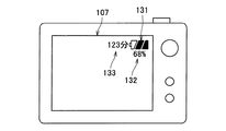
図2は、レンズ交換式カメラ本体100の液晶パネル107に、バッテリパック200の残り容量に関する情報が表示されている状態を示したものである。図2に示したものは、レンズ交換式カメラ本体100の液晶パネル107に、バッテリパック200の残り容量に関する情報として、セル欠け表示131、パーセント表示132、分表示133が表示されている。
FIG. 2 shows a state in which information relating to the remaining capacity of the battery pack 200 is displayed on the
セル欠け表示131は、バッテリパック200が満充電状態の場合には「フル」表示(セルをすべて表示する)とし、バッテリパック200の残量が無い場合には「空」表示(セルをすべて表示しない)とするものである。バッテリパック200が満充電状態と残量無しの状態との間の状態は、セル欠け表示131は、その容量に応じて表示されるセルの数が変化する。
The
パーセント表示132は、バッテリパック200が満充電状態の場合を100%とし、バッテリパック200の残量が無い場合を0%とし、それらの間の状態は、バッテリパック200の残り容量に応じて1%刻みで表示するものである。
The
分表示133は、レンズ交換式カメラ10の残り使用可能時間を、分単位で表示するものである。
The
以上、図2を用いてレンズ交換式カメラ本体100に表示される情報の例について説明した。次に、本発明の一実施形態に係るレンズ交換式カメラ10を構成する各装置の機能構成について説明する。
The example of information displayed on the interchangeable
[1−3.レンズ交換式カメラの各装置の機能構成]
図3は、本発明の一実施形態に係るレンズ交換式カメラ10を構成する各装置の機能構成を示す説明図である。以下、図3を用いて、本発明の一実施形態に係るレンズ交換式カメラ10を構成する各装置の機能構成について説明する。
[1-3. Functional configuration of each device of interchangeable lens camera]
FIG. 3 is an explanatory diagram showing a functional configuration of each device constituting the
図3に示したように、レンズ交換式カメラ本体100は、+端子101と、−端子102と、C端子103と、定電圧回路104と、マイクロコントローラ105と、シャッタボタン106と、液晶パネル107と、CCDイメージセンサ108と、メモリ109と、+端子110と、−端子111と、i端子112と、プルアップ抵抗R11と、を含んで構成される。
As shown in FIG. 3, the interchangeable
また、図3に示したように、バッテリパック200は、+端子201と、−端子202と、C端子203と、セル204a、204bと、充電保護FET TR1と、放電保護FET TR2と、電流検出抵抗R21と、マイクロコントローラ205と、を含んで構成されている。
As shown in FIG. 3, the battery pack 200 includes a +
そして、図3に示したように、交換レンズ300は、+端子301と、−端子302と、i端子303と、モータ304a、304bと、レンズ305と、絞り306と、を含んで構成される。
As shown in FIG. 3, the interchangeable lens 300 includes a +
+端子101及び−端子102は、バッテリパック200の+端子201及び−端子202と接続される端子である。バッテリパック200がレンズ交換式カメラ本体100に装着され、+端子101及び−端子102が、+端子201及び−端子202と接続されることでバッテリパック200から電力の供給を受けたり、バッテリパック200へ電力を供給したりすることができる。
The +
C端子103は、バッテリパック200のC端子203と接続される端子である。レンズ交換式カメラ本体100のC端子103と、バッテリパック200のC端子203とが接続されることで、レンズ交換式カメラ本体100は、バッテリパック200との間で通信を行うことができる。
定電圧回路104は、バッテリパック200や、外部の電源から供給される電力を一定の電圧にしてマイクロコントローラ105に供給するものである。また、定電圧回路104は、バッテリパック200から供給される電力を一定の電圧にして、交換レンズ300へ供給する機能も有する。
The
マイクロコントローラ105は、定電圧回路104から電力の供給を受けて動作することで、レンズ交換式カメラ本体100や、バッテリパック200、交換レンズ300の動作を制御するものである。
The
マイクロコントローラ105は、入出力ポート114、115、119及び入力ポート120を備え、また、バス116、117、118と接続されている。
The
シャッタボタン106は、画像の撮影のためのボタンであり、ユーザによってシャッタボタン106が押下されると、マイクロコントローラ105は入出力ポート114,115によってシャッタボタン106の押下を検出することが出きる。マイクロコントローラ105は、シャッタボタン106の押下の検出により、所定の撮像動作を実行する。
The
液晶パネル107は、撮影画像や各種情報が表示されるものである。例えば、マイクロコントローラ105は、入出力ポート114,115によって、シャッタボタン106が押されたことを検出すると、CCDイメージセンサ108のデータをバス116により取得し、取得したデータを、バス117を介してメモリ109に記録する。その後マイクロコントローラ105は、バス117を介してメモリ109から、撮影されたデータを読みだして、バス118を介して液晶パネル107への表示を行う。
The
また例えば、マイクロコントローラ105が、C端子103によるバッテリパック200との通信によって、入出力ポート119でバッテリパック200電圧、電流、電流積算値を取得すると、マイクロコントローラ105は、バッテリパック200のバッテリ残量を計算し、液晶パネル107への表示を行う。
Further, for example, when the
CCDイメージセンサ108は、撮像された被写体の画像データを得るものであり、CCDイメージセンサ108は、画像データをマイクロコントローラ105へ供給する。マイクロコントローラ105は、CCDイメージセンサ108から供給を受けた画像データをメモリ109に記録したり、液晶パネル107に表示したりする。
The
メモリ109は、撮像された被写体の画像データが記録される記録媒体である。メモリ109に記録された画像データは、ユーザ操作に基づいて液晶パネル107に表示される。
The
+端子110及び−端子111は、交換レンズ300の+端子301及び−端子302と接続される端子である。また、i端子112は、交換レンズ300のi端子302と接続される端子である。
The +
交換レンズ300がレンズ交換式カメラ本体100に装着されると、レンズ交換式カメラ本体100の+端子110、−端子111と、交換レンズ300の+端子301、−端子302とが接続されて、レンズ交換式カメラ本体100から交換レンズ300に給電が行われる。
When the interchangeable lens 300 is attached to the interchangeable
同時に、交換レンズ300がレンズ交換式カメラ本体100に装着されると、レンズ交換式カメラ本体100のi端子112と、交換レンズ300のi端子303とが接続される。レンズ交換式カメラ本体100のi端子112と、交換レンズ300のi端子303とが接続されることで、レンズ交換式カメラ本体100は交換レンズ300の装着検出ができる。
At the same time, when the interchangeable lens 300 is attached to the interchangeable
レンズ交換式カメラ本体100に交換レンズ300が装着されていないときは、マイクロコントローラ105の入力ポート120はプルアップ抵抗R11によりHighになっている。
When the interchangeable lens 300 is not attached to the interchangeable
交換レンズ300のi端子303は−端子302に繋がっているので、レンズ交換式カメラ本体100に交換レンズ300が装着されると、レンズ交換式カメラ本体100のi端子112と交換レンズ300のi端子303が接続されるので、マイクロコントローラ105の入力ポート120はLowになる。
Since the
従って、マイクロコントローラ105は、入力ポート120がHighであれば交換レンズ300は装着されていないと判断でき、入力ポート120がLowであれば交換レンズ300は装着されている、と判断できる。
Therefore, the
+端子201及び−端子202は、レンズ交換式カメラ本体100の+端子101及び−端子102と接続される端子である。バッテリパック200がレンズ交換式カメラ本体100に装着され、+端子101及び−端子102が、+端子201及び−端子202と接続されることで、バッテリパック200は、レンズ交換式カメラ本体100へ電力を供給したり、レンズ交換式カメラ本体100から電力の供給を受けたりすることができる。
The +
C端子203は、レンズ交換式カメラ本体100のC端子103と接続される端子である。レンズ交換式カメラ本体100のC端子103と、バッテリパック200のC端子203とが接続されることで、バッテリパック200は、レンズ交換式カメラ本体100との間で通信を行うことができる。
The
セル204a、204bは、レンズ交換式カメラ本体100に供給する電力を蓄えるものである。セル204a、204bに蓄えられている電力は、バッテリパック200がレンズ交換式カメラ本体100に装着され、+端子101及び−端子102が、+端子201及び−端子202と接続されることで、レンズ交換式カメラ本体100に供給される。
The
なお、本実施形態では、2つのセルが直列に接続されている構成を図示しているが、セルの接続形態はかかる例に限定されないことは言うまでもない。 In the present embodiment, a configuration in which two cells are connected in series is illustrated, but it goes without saying that the connection form of the cells is not limited to such an example.
マイクロコントローラ205は、セル204a、204bの電圧やセル204a、204bに流れる電流を測定したり、セル204a、204bに関する情報をレンズ交換式カメラ本体100に送信したりする。マイクロコントローラ205は、バッテリパック200の放電時は、セル204a、204bから供給される電力で、バッテリパック200の充電時は、+端子201および−端子202から供給される電力で動作する。
The
マイクロコントローラ205は、ADポート206、207を有しており、セル204a、204bの電圧を測定することができる。また、マイクロコントローラ205は、ADポート208、209を有しており、電流検出抵抗R21の両端の電圧を測定することが可能である。マイクロコントローラ205は、電流検出抵抗R21の抵抗値を既知の値として内蔵メモリ(図示せず)に保存しているので、電圧値を抵抗値で割ることで、バッテリパック200から放電またはバッテリパック200に充電される電流を計算できる。
The
マイクロコントローラ205は、上記の方法で測定された電圧および電流が異常な場合には、出力ポート210により充電保護FET TR1、または出力ポート211により放電保護FET TR2をOFFすることにより、セル204a、204bと、バッテリパック200に接続されるレンズ交換式カメラ本体100を保護する。
When the voltage and current measured by the above method are abnormal, the
また、マイクロコントローラ205は、新品状態のバッテリパック200における100%容量をメモリ(図示せず)に保存している。マイクロコントローラ205は、上記の方法で測定された電流を一定時間ごとに積算することで、セル204a、204bに現在溜まっている電流積算値の合計を計算し、メモリ(図示せず)に保存している。
Further, the
マイクロコントローラ205は、上記の方法で測定された電流を一定時間ごとに充電方向に流れたときのみ積算することで、セル204a、204bに現在充電された電流積算値の合計を計算し、(充放電回数=充電された電流積算値/新品状態のバッテリパック200における100%容量)で充放電回数を計算し、メモリ(図示せず)に保存している。
The
マイクロコントローラ205は、入出力ポート212を介して、上記方法で得られた、新品状態のバッテリパック200における100%容量、充放電回数、電流積算値を通信により出力することができる。入出力ポート212は、C端子203に繋がっており、バッテリパック200の外部(レンズ交換式カメラ本体100)と通信できるようになっている。
The
+端子301及び−端子302は、レンズ交換式カメラ本体100の+端子110及び−端子111と接続される端子である。また、i端子302は、レンズ交換式カメラ本体100のi端子112と接続される端子である。
The +
モータ304aは、レンズ305を駆動させるモータである。また、モータ304bは、絞り306を駆動させるモータである。モータ304aがレンズ305を動かすことでフォーカスやズームが調整され、モータ304bが絞り306を動かすことで、露出が調整される。モータ304a、304bは、+端子301及び−端子302から供給される電力で動作することになる。
The
以上、図3を用いて本発明の一実施形態に係るレンズ交換式カメラ10を構成する各装置の機能構成について説明した。次に、本発明の一実施形態にかかるレンズ交換式カメラ本体100とバッテリパック200との間の通信処理を実行する構成について説明する。
The functional configuration of each device constituting the
[1−4.通信処理を実行する構成]
図4は、本発明の一実施形態にかかるレンズ交換式カメラ本体100とバッテリパック200との間の通信処理を実行する構成を示す説明図である。以下、図4を用いて、本発明の一実施形態にかかるレンズ交換式カメラ本体100とバッテリパック200との間の通信処理を実行する構成について説明する。
[1-4. Configuration for executing communication processing]
FIG. 4 is an explanatory diagram showing a configuration for executing communication processing between the interchangeable
図4に示したように、レンズ交換式カメラ本体100のマイクロコントローラ105は、入出力ポート141と、GND142と、CPU143と、入力バッファ144と、出力バッファ145と、プルアップ抵抗R12と、出力FET TR11と、プルアップダイオードD11と、を含んで構成される。
As shown in FIG. 4, the
一方、図5に示したように、バッテリパック200のマイクロコントローラ205は、入出力ポート221と、GND222と、CPU223と、入力バッファ224と、出力バッファ225と、プルアップ抵抗R22と、出力FET TR21と、プルアップダイオードD21と、を含んで構成される。
On the other hand, as shown in FIG. 5, the
バッテリパック200のマイクロコントローラ205のGND222は、バッテリパック200の−端子202、レンズ交換式カメラ本体100の−端子102を介して、レンズ交換式カメラ本体100のマイクロコントローラ105のGND142と接続されている。
The
バッテリパック200のマイクロコントローラ205の入出力ポート221は、バッテリパック200のC端子203、レンズ交換式カメラ本体100のC端子103を介して、レンズ交換式カメラ本体100のマイクロコントローラ105の入出力ポート141と接続されている。
The input /
バッテリパック200のマイクロコントローラ205が、バッテリパック200のC端子203にLowを出力したい場合は、マイクロコントローラ205は、出力バッファ225でHighを出力する。すると、出力FET TR21がONして、入出力ポート221はLowになり、C端子203がLowになる。
When the
一方、バッテリパック200のマイクロコントローラ205が、バッテリパック200のC端子203にHighを出力したい場合は、マイクロコントローラ205は、出力バッファ225でLowを出力する。すると、出力FET TR21がOFFして、入出力ポート221はプルアップ抵抗r22及びプルアップダイオードD21によりHighになり、C端子203がHighになる。
On the other hand, when the
バッテリパック200のマイクロコントローラ205が、バッテリパック200のC端子203がHighであるかLowであるかを知りたい場合は、入力バッファ224を介して知ることができる。
When the
レンズ交換式カメラ本体100のマイクロコントローラ105が、レンズ交換式カメラ本体100のC端子103にLowを出力したい場合は、マイクロコントローラ105は、出力バッファ145でHighを出力する。すると、出力FET TR11がONして、入出力ポート141はLowになり、C端子103がLowになる。
When the
一方、レンズ交換式カメラ本体100のマイクロコントローラ105が、レンズ交換式カメラ本体100のC端子103にHighを出力したい場合は、マイクロコントローラ105は、出力バッファ145でLowを出力する。すると、出力FET TR11がOFFして、入出力ポート141はプルアップ抵抗R12及びプルアップダイオードD11によりHighになり、C端子103がHighになる。
On the other hand, when the
レンズ交換式カメラ本体100のマイクロコントローラ105が、レンズ交換式カメラ本体100のC端子103がHighであるかLowであるかを知りたい場合は、入力バッファ144を介して知ることができる。
When the
図5は、レンズ交換式カメラ本体100とバッテリパック200との間の通信タイミングチャートを示す説明図である。
FIG. 5 is an explanatory diagram showing a communication timing chart between the interchangeable
レンズ交換式カメラ本体100とバッテリパック200との間で通信が行われる前は、バッテリパック200の出力FET TR21と、レンズ交換式カメラ本体100の出力FET TR11とがいずれもOFFになっており、通信ラインはHighとなっている(符号151)。
Before communication is performed between the interchangeable-
通信開始時には、レンズ交換式カメラ本体100のマイクロコントローラ105は、出力FET TR11を、通信データ1ビット相当分の時間だけONにして、通信ラインをLowにする(符号152)。レンズ交換式カメラ本体100のマイクロコントローラ105及びバッテリパック200のマイクロコントローラ205は、この通信データ1ビット相当分のLow区間を基に、通信のタイミングの同期をとる。
At the start of communication, the
次に、レンズ交換式カメラ本体100のマイクロコントローラ105は、コマンド8ビットを送信する(符号153)。レンズ交換式カメラ本体100のマイクロコントローラ105は、High出力のビットでは出力FET TR11をOFFし、Low出力のビットでは出力FET TR12をONする。
Next, the
バッテリパック200のマイクロコントローラ205は、入力バッファ224を介して、レンズ交換式カメラ本体100のマイクロコントローラ105から送られてくるHigh/Lowの出力を受信する。
The
次に、レンズ交換式カメラ本体100のマイクロコントローラ105は、ストップビット2ビットを送信する(符号154)。バッテリパック200のマイクロコントローラ205は、ストップビット2ビットで、通信終了を確認する。
Next, the
次に、再びレンズ交換式カメラ本体100のマイクロコントローラ105は、出力FET TR11を、通信データ1ビット相当分の時間だけONにして、通信ラインをLowにする(符号155)。
Next, the
次に、バッテリパック200のマイクロコントローラ205は、レスポンス8ビットを送信する(符号156)。バッテリパック200のマイクロコントローラ205は、High出力のビットでは、出力FET TR21をOFFし、Low出力のビットでは出力FET TR21をONする。
Next, the
レンズ交換式カメラ本体100のマイクロコントローラ105は、入力バッファ144を介してHigh/Lowを受信する。
The
次に、レンズ交換式カメラ本体100のマイクロコントローラ105は、ストップビット2ビットを送信する(符号157)。バッテリパック200のマイクロコントローラ205は、ストップビット2ビットで、通信終了を確認する。
Next, the
上記の一連の流れによって、レンズ交換式カメラ本体100とバッテリパック200との間の1回の通信が完了する。
Through the series of flows described above, one-time communication between the interchangeable
図6は、レンズ交換式カメラ本体100とバッテリパック200との間で伝達される通信データの内容の一例を示す説明図である。
FIG. 6 is an explanatory diagram showing an example of the content of communication data transmitted between the interchangeable
レンズ交換式カメラ本体100のマイクロコントローラ105が、コマンド(符号153)として「0x01」(符号181)を送信すると、バッテリパック200のマイクロコントローラ205は、レスポンス(符号156)として電流値(符号182)を送信する。
When the
レンズ交換式カメラ本体100のマイクロコントローラ105が、コマンド(符号153)として「0x02」(符号183)を送信すると、バッテリパック200のマイクロコントローラ205は、レスポンス(符号156)として電圧値(符号184)を送信する。
When the
レンズ交換式カメラ本体100のマイクロコントローラ105が、コマンド(符号153)として「0x03」(符号185)を送信すると、バッテリパック200のマイクロコントローラ205は、レスポンス(符号156)として電流積算値(符号186)を送信する。
When the
もちろん、図6に示したコマンド及びレスポンスは一例であり、本発明においてはかかる例に限定されないことは言うまでもない。また、図5に示した各データのビット数についても、本発明においてはかかる例に限定されないことは言うまでもない。 Of course, the commands and responses shown in FIG. 6 are merely examples, and it goes without saying that the present invention is not limited to such examples. Further, it goes without saying that the number of bits of each data shown in FIG. 5 is not limited to such an example in the present invention.
以上、本発明の一実施形態にかかるレンズ交換式カメラ本体100とバッテリパック200との間の通信処理を実行する構成について説明した。次に、本発明の一実施形態にかかるレンズ交換式カメラ10の動作について説明する。
The configuration for executing the communication process between the interchangeable
[1−5.レンズ交換式カメラの動作]
図7及び図8は、本発明の一実施形態にかかるレンズ交換式カメラ10の動作を示す流れ図である。以下、図7及び図8を用いて本発明の一実施形態にかかるレンズ交換式カメラ10の動作について説明する。
[1-5. Operation of interchangeable lens camera]
7 and 8 are flowcharts showing the operation of the
レンズ交換式カメラ10のユーザによって、レンズ交換式カメラ10のレンズ交換式カメラ本体100の電源がオンされると、レンズ交換式カメラ本体100のマイクロコントローラ105が、バッテリパック200の使用可能時間を表示する処理を実行する。
When the user of the
レンズ交換式カメラ本体100のマイクロコントローラ105は、レンズ交換式カメラ本体100の電源がオンされると、レンズ装着直後フラグが1であるかどうかを判断する(ステップS101)。このレンズ装着直後フラグは、マイクロコントローラ105に記録されるフラグであり、レンズ交換式カメラ本体100に交換レンズ300が装着された直後(レンズ交換後1回目の電源投入)であることを示すフラグである。なお、交換レンズ300は、レンズ交換式カメラ本体100が予め消費電力を知ることが出来ないデバイスである。
When the power supply of the interchangeable
上記ステップS101の判断の結果、レンズ装着直後フラグが1であった場合には、レンズ交換式カメラ本体100のマイクロコントローラ105は、バッテリパック200のマイクロコントローラ205との通信によって、バッテリパック200の電圧の値を取得(ステップS102)するとともに、バッテリパック200を流れる電流の値を取得(ステップS103)する。
As a result of the determination in step S101, if the flag immediately after the lens attachment is 1, the
上記ステップS102及びステップS103において、バッテリパック200の電圧の値及びバッテリパック200を流れる電流の値を取得したマイクロコントローラ105は、これらの値を乗算することによって、バッテリパック200の電力値を算出する(ステップS104)。マイクロコントローラ105は、算出した電力値を内部に保存する。
In step S102 and step S103, the
上記ステップS104でバッテリパック200の電力値を算出すると、続いてマイクロコントローラ105は、レンズ交換式カメラ10が撮影処理を実行中であるかどうかを判断する(ステップS105)。
When the power value of the battery pack 200 is calculated in step S104, the
上記ステップS105の判断の結果、レンズ交換式カメラ10が撮影処理を実行中であった場合には、マイクロコントローラ105は、上記ステップS104で算出した電力値の合計値を、上記ステップS105で、レンズ交換式カメラ10が撮影処理を実行中であると判断された回数で割ることで、平均電力を算出する(ステップS106)。マイクロコントローラ105は、上記ステップS106で平均電力を算出すると、その平均電力の値を内部に保存する(ステップS107)。
As a result of the determination in step S105, if the
一方、上記ステップS105の判断の結果、レンズ交換式カメラ10が撮影処理を実行中でなかった場合には、上記ステップS106及びステップS107の処理はスキップされる。
On the other hand, as a result of the determination in step S105, when the
続いてマイクロコントローラ105は、レンズ交換式カメラ10のユーザによって、レンズ交換式カメラ10のレンズ交換式カメラ本体100の電源がオフされたかどうかを判断する(ステップS108)。
Subsequently, the
上記ステップS108の判断の結果、レンズ交換式カメラ10のユーザによって、レンズ交換式カメラ10のレンズ交換式カメラ本体100の電源がオフされたと判断した場合は、マイクロコントローラ105は、レンズ装着直後フラグを0に更新して(ステップS109)、レンズ交換式カメラ本体100の電源をオフする。一方、上記ステップS108の判断の結果、レンズ交換式カメラ10のユーザによって、レンズ交換式カメラ10のレンズ交換式カメラ本体100の電源がオフされていないとマイクロコントローラ105が判断した場合は、上記ステップS102に戻る。
As a result of the determination in step S108, when the user of the
上記ステップS101の判断の結果、レンズ装着直後フラグが1でなかった(0であった)場合には、レンズ交換式カメラ本体100のマイクロコントローラ105は、バッテリパック200のマイクロコントローラ205との通信によって、バッテリパック200の電流積算値を取得する(ステップS110)。
If the flag immediately after the lens attachment is not 1 (0) as a result of the determination in step S101, the
上記ステップS110で、マイクロコントローラ105がバッテリパック200の電流積算値を取得すると、続いてマイクロコントローラ105は、上記ステップS106で算出した平均電力と、上記ステップS110で取得した電流積算値とから、バッテリパック200のバッテリ使用可能時間を計算し、計算したバッテリ使用可能時間を液晶パネル107へ表示する(ステップS111)。
When the
ここでマイクロコントローラ105は、バッテリ使用可能時間を、
(A/B)×(D/C)
により計算する。
ただし、
A:「電流積算値(単位:Ah)」
B:「満充電時の電流積算値(単位:Ah)」
C:「平均電力(単位:W)」89
D:「満充電バッテリを1Wで使った場合の使用可能時間(単位:W・分)」
であり、B及びDは、あらかじめマイクロコントローラ105に固定値を記憶させておいて使用する。
Here, the
(A / B) x (D / C)
Calculate according to
However,
A: “Current integrated value (unit: Ah)”
B: “Current integrated value at full charge (unit: Ah)”
C: “Average power (unit: W)” 89
D: “Available time when a fully charged battery is used at 1 W (unit: W · min)”
B and D are used by storing a fixed value in the
上記ステップS111で、マイクロコントローラ105がバッテリパック200のバッテリ使用可能時間を液晶パネル107へ表示すると、続いてマイクロコントローラ105は、レンズ交換式カメラ10のユーザによって、レンズ交換式カメラ10のレンズ交換式カメラ本体100の電源がオフされたかどうかを判断する(ステップS112)。
When the
上記ステップS112の判断の結果、レンズ交換式カメラ10のユーザによって、レンズ交換式カメラ10のレンズ交換式カメラ本体100の電源がオフされたと判断した場合は、マイクロコントローラ105はレンズ交換式カメラ本体100の電源をオフする。一方、上記ステップS112の判断の結果、レンズ交換式カメラ10のユーザによって、レンズ交換式カメラ10のレンズ交換式カメラ本体100の電源がオフされていないとマイクロコントローラ105が判断した場合は、上記ステップS110に戻る。
If the user of the
レンズ装着直後フラグは、レンズ交換式カメラ本体100に対する交換レンズ300の装着がされた時点で1に設定される。図8は、レンズ交換式カメラ本体100に交換レンズ300が装着された際の処理を示す流れ図である。
The immediately after lens mounting flag is set to 1 when the interchangeable lens 300 is mounted on the interchangeable
レンズ交換式カメラ本体100に交換レンズ300が装着されたことをマイクロコントローラ105が検出すると、マイクロコントローラ105は、レンズ装着直後フラグを1に設定する(ステップS121)。これにより、レンズ交換式カメラ本体100に交換レンズ300が装着された直後であることを、マイクロコントローラ105は認識することができる。
When the
図9は、レンズ交換式カメラ10の消費電力と、バッテリパック200のバッテリ使用可能時間の表示との関係をタイミングチャートで示す説明図である。
FIG. 9 is an explanatory diagram showing the relationship between the power consumption of the
レンズ交換後1回目の、レンズ交換式カメラ本体100の電源オンが行われると、バッテリパック200の電力が消費され始める。撮影開始前の電力は、上記ステップS106における平均電力の計算には用いられない。一方、撮影開始後の電力は、上記ステップS106における平均電力の計算に用いられる。
When the power of the lens-
また、撮影終了後の電力は、上記ステップS106における平均電力の計算には用いられない。レンズ交換後1回目のレンズ交換式カメラ本体100の電源オンから電源オフまでの間は、液晶パネル107にはバッテリ使用可能時間(分)の表示は行わない。
Further, the power after photographing is not used for the calculation of the average power in step S106. The battery usable time (minutes) is not displayed on the
その後、レンズ交換後2回目以降のレンズ交換式カメラ本体100の電源オンが行われると、レンズ交換後1回目のカメラ本体の電源オンから電源オフまでの間に計算された平均電力を使って、マイクロコントローラ105によって、直ちに液晶パネル107にバッテリ使用可能時間(分)表示が行われる。バッテリ使用可能時間(分)は、レンズ交換後2回目以降のレンズ交換式カメラ本体100の電源オフまで、同じ平均電力を使って計算される。
After that, when the power of the lens-
このように、レンズ交換後1回目におけるレンズ交換式カメラ本体100の電源オンから電源オフまでの間に算出した平均電力の情報を用いることで、レンズ交換後2回目以降において、レンズ交換式カメラ本体100に装着されたバッテリパック200の、より正確なバッテリ使用可能時間を計算して、液晶パネル107に表示することができる。
As described above, by using the information on the average power calculated from the power-on to the power-off of the lens-interchangeable camera
次に、バッテリ使用可能時間の別の計算例について説明する。レンズ交換式カメラ10には、静止画のみを撮影するもの、静止画と動画の両方を撮影できるもの、動画撮影の際の画質を選択できるもの、撮影した動画の再生ができるもの等がある。そして、レンズ交換式カメラ10は、動作によって消費電力が異なる。以下の説明では、レンズ交換式カメラ10の動作によって異なる消費電力の情報が格納された「消費電力テーブル」を用いて、レンズ交換式カメラ10の消費電力を求め、その消費電力を用いてバッテリ使用可能時間を計算する場合を説明する。
Next, another calculation example of the battery usable time will be described. The
図10は、本発明の一実施形態にかかるレンズ交換式カメラ10の消費電力テーブル400の一例を示す説明図である。
FIG. 10 is an explanatory diagram showing an example of the power consumption table 400 of the
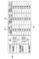
図10に示した消費電力テーブル400の、カメラ本体消費電力401は、交換レンズ300をレンズ交換式カメラ本体100に装着しない場合の消費電力が記録されている。この消費電力は、レンズ交換式カメラ本体100のみに依存するものであるので、レンズ交換式カメラ本体100の出荷時に予め知ることが出来る。従って、このカメラ本体消費電力401の情報は、マイクロコントローラ105に予め記録した状態でレンズ交換式カメラ本体100が出荷される。
In the power consumption table 400 of the power consumption table 400 shown in FIG. 10, the power consumption when the interchangeable lens 300 is not attached to the interchangeable
ユーザが、レンズ交換式カメラ本体100に交換レンズ300を装着して、1回目にレンズ交換式カメラ本体100の電源がオンされると、その時の動作モードにおける消費電力は実測で求めることができるが、それ以外の動作モードにおける消費電力は、その実測値から計算で求めることができる。
When the user attaches the interchangeable lens 300 to the interchangeable
例えば図10に示した例では、レンズ交換式カメラ本体100に交換レンズ300を装着して1回目にレンズ交換式カメラ本体100の電源がオンされて、符号402で示した動画撮影(HD 1920)を行うと、交換レンズ込み消費電力403の値は実測値をそのまま使用する。
For example, in the example shown in FIG. 10, the interchangeable lens 300 is attached to the interchangeable
この時、交換レンズ込み消費電力403とカメラ本体消費電力401との差(500[mW))が、交換レンズ300の消費電力である。そして、交換レンズ300の消費電力は、撮影時には撮影モードに限らず一定であるので、動画撮影(HD 1440)、動画撮影(SD)及び静止画撮影時の交換レンズ込み消費電力403は、カメラ本体消費電力401にその差(500[mW))を加えることで、計算で求めることが可能である。
At this time, the difference (500 [mW)) between the
また、動画再生(HD 1920、HD 1440、SD)及び静止画再生時は、交換レンズ300で電力が消費されないので、カメラ本体消費電力401を、そのまま交換レンズ込み消費電力403として使用することができる。
In addition, during moving image playback (
そして、ユーザが、レンズ交換式カメラ本体100に交換レンズ300を装着して、2回目以降にレンズ交換式カメラ本体100の電源がオンされると、マイクロコントローラ105は、このように決められた交換レンズ込み消費電力403を用いることで、レンズ交換式カメラ10がどの動作モードで動作しても、消費電力テーブル400を参照して正しいバッテリ使用可能時間を算出し、液晶パネル107へ表示することができる。
Then, when the user attaches the interchangeable lens 300 to the interchangeable
図10に示した消費電力テーブル400を用いてバッテリ使用可能時間を算出する際には、さらに、各動作モード時において、交換レンズ300の動作時の消費電力の違いを考慮することで、より正確なバッテリ使用可能時間を算出できる。 When calculating the battery usable time using the power consumption table 400 shown in FIG. 10, it is more accurate by considering the difference in power consumption during the operation of the interchangeable lens 300 in each operation mode. The battery usable time can be calculated.
図11は、本発明の一実施形態にかかるレンズ交換式カメラ10の消費電力テーブル500の一例を示す説明図である。図11に示した消費電力テーブル500は、マイクロコントローラ105に記録されている。
FIG. 11 is an explanatory diagram showing an example of the power consumption table 500 of the
図11に示した消費電力テーブル500は、交換レンズ300のモータ304a、304bを動かさない待機時撮影の待機時、オートフォーカス処理時及びオート露出処理時の消費電力の差分が記録されているテーブルであり、この図11に示した値が図10の消費電力テーブル400の消費電力値に加算されることで、当該処理実行時の消費電力が分かる。
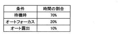
The power consumption table 500 shown in FIG. 11 is a table that records the difference in power consumption during standby shooting without moving the
標準的なユーザは、動画撮影を行う場合と、静止画撮影を行う場合とでは、交換レンズ300のモータ304a、304bを動かさない待機時、オートフォーカス処理時、およびオート露出処理時の使用時間の割合が異なる。図12は、動画撮影を行う場合における待機時、オートフォーカス処理時、オート露出処理時の使用時間の割合の一例を示す説明図であり、図13は、静止画撮影を行う場合における待機時、オートフォーカス処理時、オート露出処理時の使用時間の割合の一例を示す説明図である。この使用時間の割合の情報も、マイクロコントローラ105に記録されている。
In a case where a standard user performs moving image shooting and still image shooting, the usage time during standby, autofocus processing, and auto exposure processing in which the
そして、図11に示した消費電力テーブル500及び、図12,図13に示した動画撮影時及び静止画撮影時の使用時間の割合の情報を用いることで、より正確なバッテリ使用可能時間を計算し、画面に表示させることができる。 Then, by using the power consumption table 500 shown in FIG. 11 and the information of the usage time ratio at the time of moving image shooting and still image shooting shown in FIGS. 12 and 13, a more accurate battery usable time is calculated. And can be displayed on the screen.
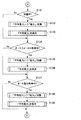
図14は、本発明の一実施形態にかかるレンズ交換式カメラ10の動作を示す流れ図である。図14に示した流れ図は、図7に示した流れ図のうち、ステップS105からステップS107に置き換えられるものであり、それ以外の動作については図7に示したものと変わらない。
FIG. 14 is a flowchart showing the operation of the
まず、レンズ交換式カメラ10が、交換レンズ300のモータ304a、304bを動かさない待機中の状態であるかどうかをマイクロコントローラ105が判断する(ステップS131)。
First, the
上記ステップS131の判断の結果、レンズ交換式カメラ10が待機中の状態であった場合には、マイクロコントローラ105は、上記ステップS104で算出した電力値の合計値を、上記ステップS131で、レンズ交換式カメラ10が待機中の状態であると判断された回数で割ることで、平均電力を算出する(ステップS132)。マイクロコントローラ105は、上記ステップS132で平均電力を算出すると、その平均電力の値を内部に保存する(ステップS133)。
If the result of determination in step S131 is that the
一方、上記ステップS131の判断の結果、レンズ交換式カメラ10が撮影処理を実行中でなかった場合には、上記ステップS132及びステップS133の処理はスキップされる。
On the other hand, if the result of the determination in step S131 is that the
次に、レンズ交換式カメラ10が、オートフォーカス処理中の状態であるかどうかをマイクロコントローラ105が判断する(ステップS134)。
Next, the
上記ステップS134の判断の結果、レンズ交換式カメラ10がオートフォーカス処理中の状態であった場合には、マイクロコントローラ105は、上記ステップS104で算出した電力値の合計値を、上記ステップS134で、レンズ交換式カメラ10がオートフォーカス処理中の状態であると判断された回数で割ることで、平均電力を算出する(ステップS135)。マイクロコントローラ105は、上記ステップS135で平均電力を算出すると、その平均電力の値を内部に保存する(ステップS136)。
If the result of determination in step S134 is that the
一方、上記ステップS134の判断の結果、レンズ交換式カメラ10が撮影処理を実行中でなかった場合には、上記ステップS135及びステップS136の処理はスキップされる。
On the other hand, as a result of the determination in step S134, when the
続いて、レンズ交換式カメラ10が、オート露出処理中の状態であるかどうかをマイクロコントローラ105が判断する(ステップS137)。
Subsequently, the
上記ステップS134の判断の結果、レンズ交換式カメラ10がオート露出処理中の状態であった場合には、マイクロコントローラ105は、上記ステップS104で算出した電力値の合計値を、上記ステップS137で、レンズ交換式カメラ10がオート露出処理中の状態であると判断された回数で割ることで、平均電力を算出する(ステップS138)。マイクロコントローラ105は、上記ステップS138で平均電力を算出すると、その平均電力の値を内部に保存する(ステップS139)。
If the result of the determination in step S134 is that the
一方、上記ステップS137の判断の結果、レンズ交換式カメラ10が撮影処理を実行中でなかった場合には、上記ステップS138及びステップS139の処理はスキップされる。
On the other hand, as a result of the determination in step S137, if the
この一連の流れにより、レンズ交換式カメラ10が待機中の状態における平均電力、オートフォーカス処理中の平均電力、及びオート露出処理中の平均電力が求められる。そして、これらの平均電力から、レンズ交換式カメラ本体100の消費電力(図10の符号401で示した情報)を引くと、レンズ交換式カメラ10が待機中の状態における平均電力、オートフォーカス処理中の平均電力、及びオート露出処理中の平均電力の、それぞれの差分が求められる。
With this series of flows, the average power when the
動画撮影時の、交換レンズ300を含めた消費電力からレンズ交換式カメラ本体100の消費電力を引いた値は、以下のように求める事ができる。
A×P1/100+B×P2/100+C×P3/100
(A:待機中の平均電力の差分
B:オートフォーカス中の平均電力の差分
C:オート露出中の平均電力の差分
P1:動画撮影時の待機中の使用時間割合
P2:動画撮影時のオートフォーカス中の使用時間割合
P3:動画撮影時のオート露出中の使用時間割合)
The value obtained by subtracting the power consumption of the interchangeable
A × P1 / 100 + B × P2 / 100 + C × P3 / 100
(A: Difference in average power during standby B: Difference in average power during autofocus C: Difference in average power during auto exposure P1: Proportion of use time during standby during movie shooting P2: Autofocus during movie shooting Usage time ratio during P3: Usage time ratio during auto exposure during movie shooting)
一方、静止画撮影時の、交換レンズ300を含めた消費電力からレンズ交換式カメラ本体100の消費電力を引いた値は、以下のように求める事ができる。
A×Q1/100+B×Q2/100+C×Q3/100
(A:待機中の平均電力の差分
B:オートフォーカス中の平均電力の差分
C:オート露出中の平均電力の差分
Q1:静止画撮影時の待機中の使用時間割合
Q2:静止画撮影時のオートフォーカス中の使用時間割合
Q3:静止画撮影時のオート露出中の使用時間割合)
On the other hand, the value obtained by subtracting the power consumption of the interchangeable
A × Q1 / 100 + B × Q2 / 100 + C × Q3 / 100
(A: Difference in average power during standby B: Difference in average power during autofocus C: Difference in average power during auto exposure Q1: Ratio of use time during standby during still image shooting Q2: During still image shooting Usage ratio during autofocus Q3: Usage ratio during auto exposure during still image shooting
このように、交換レンズ300を含めた消費電力からレンズ交換式カメラ本体100の消費電力を引いた値を求めることで、交換レンズ300の消費電力が分かり、より正確なバッテリ使用可能時間を算出できる。
As described above, by obtaining a value obtained by subtracting the power consumption of the interchangeable
なお、上述の例では、待機時、オートフォーカス処理時、オート露出処理時の使用時間の割合を、あらかじめマイクロコントローラ105に保存することで、交換レンズ300の消費電力を求めていたが、本発明はかかる例に限定されない。つまり、使用時間の割合を、あらかじめマイクロコントローラ105に保存しなくても、実際にこれらの処理が使われた回数を、上述した図14の処理におけるステップS131、S134、S137で、それぞれYESと判断された回数を数えて、その回数の割合を使用しても良い。このようにすると、個別のユーザのカメラの使い方の癖といったものを消費電力計算に反映できるので、より正確なバッテリ使用可能時間を計算し、画面に表示することができる。
In the above-described example, the power consumption of the interchangeable lens 300 is obtained by preliminarily storing the ratio of the usage time during standby, autofocus processing, and auto exposure processing in the
交換レンズ300の脱着の判断は、レンズ交換式カメラ本体100のi端子112によって行ってもよく、直前に算出した平均電力と、最新の平均電力との差分が一定値以上の場合は、レンズ交換式カメラ本体100に交換レンズ300が交換されたと判断してもよい。その場合は、最新の平均電力をマイクロコントローラ105に保存し、その値を、その後のバッテリ使用可能時間の計算に用いてもよい。
The determination of the attachment / detachment of the interchangeable lens 300 may be performed by the
上述の例では、レンズ交換後に最初にレンズ交換式カメラ本体100の電源がオンになった場合は、平均電力の算出だけを行い、バッテリ使用可能時間の計算及び表示をさせていなかったが、レンズ交換後に最初にレンズ交換式カメラ本体100の電源がオンになった場合は、出荷時に同梱されている交換レンズや、使用が推奨される交換レンズなどの平均電力を用いて、バッテリ使用可能時間の計算及び表示をさせてもよい。
In the above-described example, when the power of the interchangeable
また、上述の例では、レンズ交換後に最初にレンズ交換式カメラ本体100の電源がオンになった場合は、平均電力の算出だけを行い、バッテリ使用可能時間の計算及び表示をさせていなかったが、レンズ交換後に最初にレンズ交換式カメラ本体100の電源がオンになった場合に、平均電力を算出するために十分なデータが取得でき、平均電力を計算できたときは、その時点で、その平均電力の情報を用いて、バッテリ使用可能時間の計算及び表示をさせてもよい。
In the above example, when the power of the interchangeable
また例えば、マイクロコントローラ105は、バッテリ使用可能時間を計算し、レンズ交換式カメラ本体100に内蔵される記録メディアの記録可能時間と比較して、記録メディアの記録可能時間の方が短ければ、液晶パネル107に所定の警告表示をさせるようにしてもよい。
Further, for example, the
<2.まとめ>
以上説明したように本発明の一実施形態によれば、交換レンズ300のように、予め消費電力を知ることができないデバイスがレンズ交換式カメラ本体100に装着される場合は、従来求めることができなかったバッテリ使用可能時間を算出して、その時間の情報を表示することができる。
<2. Summary>
As described above, according to an embodiment of the present invention, when a device whose power consumption cannot be known in advance, such as the interchangeable lens 300, is attached to the interchangeable
本発明の一実施形態によれば、消費電力が予め分かっているデバイスの組み合わせのみでシステムが成り立つ場合に限らず、交換レンズ300のように予め消費電力を知ることができないデバイスがレンズ交換式カメラ本体100に装着される場合は、従来求めることができなかったバッテリ使用可能時間を算出して、その時間の情報を表示することができる。
According to an embodiment of the present invention, not only a case where the system is configured only by a combination of devices whose power consumption is known in advance, but a device that cannot know power consumption in advance, such as the interchangeable lens 300, is an interchangeable lens camera. When mounted on the
本発明の一実施形態によれば、同じデバイスであっても、ユーザの使い方によって消費電力が異なる場合において、従来求めることができなかったバッテリ使用可能時間を算出して、その時間の情報を表示することができる。 According to an embodiment of the present invention, even when the power consumption is different depending on how the user uses the same device, the battery usable time that could not be obtained in the past is calculated and information about the time is displayed. can do.
また、本発明の一実施形態によれば、交換レンズ300のように、予め消費電力を知ることができないデバイスが装着されて1回目に電源がオンされた場合の動作モードにおける消費電力を実測するだけで、2回目以降に電源がオンされたときは、すべての動作モードにおいてバッテリ使用可能時間を算出して、その時間の情報を表示することができる。 In addition, according to an embodiment of the present invention, the power consumption in the operation mode is measured when a device whose power consumption cannot be known in advance, such as the interchangeable lens 300, is mounted and the power is turned on for the first time. Thus, when the power is turned on for the second time and thereafter, the battery usable time can be calculated in all the operation modes, and information on the time can be displayed.
なお、上記の実施形態で説明した一連の処理は、専用のハードウエアによって実行させても良いが、ソフトウエア(アプリケーション)により実行させても良い。一連の処理をソフトウエアに行わせる場合には、汎用又は専用のコンピュータにコンピュータプログラムを実行させることにより、上記の一連の処理を実現することができる。 The series of processes described in the above embodiment may be executed by dedicated hardware, but may be executed by software (application). When a series of processing is performed by software, the above-described series of processing can be realized by causing a general-purpose or dedicated computer to execute a computer program.
以上、添付図面を参照しながら本発明の好適な実施形態について詳細に説明したが、本発明はかかる例に限定されない。本発明の属する技術の分野における通常の知識を有する者であれば、特許請求の範囲に記載された技術的思想の範疇内において、各種の変更例または修正例に想到し得ることは明らかであり、これらについても、当然に本発明の技術的範囲に属するものと了解される。 The preferred embodiments of the present invention have been described in detail above with reference to the accompanying drawings, but the present invention is not limited to such examples. It is obvious that a person having ordinary knowledge in the technical field to which the present invention pertains can come up with various changes or modifications within the scope of the technical idea described in the claims. Of course, it is understood that these also belong to the technical scope of the present invention.
例えば、上記実施形態では、電流積算値の情報はバッテリパック200からレンズ交換式カメラ本体に送信するようにしていたが、本発明はかかる例に限定されない。すなわち、電流積算値の情報は、バッテリパック200が計測した電流値の情報を、レンズ交換式カメラ本体100のマイクロコントローラ105がバッテリパック200から逐次受信し、マイクロコントローラ105で計算するようにしてもよい。
For example, in the above embodiment, the information of the current integrated value is transmitted from the battery pack 200 to the interchangeable lens camera body, but the present invention is not limited to such an example. That is, the information on the current integrated value may be calculated by the
10 レンズ交換式カメラ
100 レンズ交換式カメラ本体
101 +端子
102 −端子
103 C端子
104 定電圧回路
105 マイクロコントローラ
106 シャッタボタン
107 液晶パネル
108 CCDイメージセンサ
109 メモリ
110 +端子
111 −端子
112 i端子
200 バッテリパック
201 +端子
202 −端子
203 C端子
204a、204b セル
205 マイクロコントローラ
300 交換レンズ
301 +端子
302 −端子
303 i端子
304a、304b モータ
305 レンズ
306 絞り
DESCRIPTION OF
Claims (9)
前記使用可能時間算出部は、
予め消費電力を知ることができない部品が電源投入後最初に接続された場合に、該部品を接続した状態で所定の動作モードで動作させた場合の平均電力を実測し、
前記部品が引き続き接続されている状態で2度目以降の電源投入時に、前記平均電力及び前記バッテリ装置の充放電時に流れる電流の積算値である電流積算値を用いて前記バッテリ装置の使用可能時間を算出する、撮像装置。 A usable time calculating unit for calculating a usable time of a battery device having a secondary battery that is mounted;
The usable time calculation unit
When a component whose power consumption cannot be known in advance is connected for the first time after turning on the power, the average power when the component is connected and operated in a predetermined operation mode is measured,
When the power supply is turned on for the second time or later in a state in which the components are continuously connected, the usable time of the battery device is determined by using the average power and a current integrated value that is an integrated value of a current that flows during charging and discharging of the battery device. An imaging device to calculate.
前記使用可能時間算出部は、前記バッテリ装置の使用可能時間を前記表示部に表示させる、請求項1に記載の撮像装置。 A display unit for displaying information;
The imaging device according to claim 1, wherein the usable time calculation unit displays the usable time of the battery device on the display unit.
前記使用可能時間算出ステップは、
予め消費電力を知ることができない部品が電源投入後最初に接続された場合に、該部品を接続した状態で所定の動作モードで動作させた場合の平均電力を実測し、
前記部品が引き続き接続されている状態で2度目以降の電源投入時に、前記平均電力及び前記バッテリ装置の充放電時に流れる電流の積算値である電流積算値を用いて前記バッテリ装置の使用可能時間を算出する、撮像装置の使用可能時間算出方法。
A usable time calculating step for calculating a usable time of a battery device having a secondary battery that is mounted;
The usable time calculating step includes:
When a component whose power consumption cannot be known in advance is connected for the first time after turning on the power, the average power when the component is connected and operated in a predetermined operation mode is measured,
When the power supply is turned on for the second time or later in a state in which the components are continuously connected, the usable time of the battery device is determined by using the average power and a current integrated value that is an integrated value of a current that flows during charging and discharging of the battery device. A method for calculating an available time of the imaging apparatus.
Priority Applications (5)
| Application Number | Priority Date | Filing Date | Title |
|---|---|---|---|
| JP2010284584A JP2012134727A (en) | 2010-12-21 | 2010-12-21 | Imaging apparatus and available time calculation method for imaging apparatus |
| US13/287,286 US8577219B2 (en) | 2010-12-21 | 2011-11-02 | Imaging apparatus and method of calculating usable time of imaging apparatus |
| EP11190872A EP2469639A2 (en) | 2010-12-21 | 2011-11-28 | Imaging apparatus and method of calculating usable time of imaging apparatus |
| CN2011104165495A CN102566209A (en) | 2010-12-21 | 2011-12-14 | Imaging apparatus and method of calculating usable time of imaging apparatus |
| US14/061,241 US8934767B2 (en) | 2010-12-21 | 2013-10-23 | Imaging apparatus and method of calculating usable time of imaging apparatus |
Applications Claiming Priority (1)
| Application Number | Priority Date | Filing Date | Title |
|---|---|---|---|
| JP2010284584A JP2012134727A (en) | 2010-12-21 | 2010-12-21 | Imaging apparatus and available time calculation method for imaging apparatus |
Publications (1)
| Publication Number | Publication Date |
|---|---|
| JP2012134727A true JP2012134727A (en) | 2012-07-12 |
Family
ID=45421839
Family Applications (1)
| Application Number | Title | Priority Date | Filing Date |
|---|---|---|---|
| JP2010284584A Ceased JP2012134727A (en) | 2010-12-21 | 2010-12-21 | Imaging apparatus and available time calculation method for imaging apparatus |
Country Status (4)
| Country | Link |
|---|---|
| US (2) | US8577219B2 (en) |
| EP (1) | EP2469639A2 (en) |
| JP (1) | JP2012134727A (en) |
| CN (1) | CN102566209A (en) |
Families Citing this family (4)
| Publication number | Priority date | Publication date | Assignee | Title |
|---|---|---|---|---|
| JP2012134727A (en) * | 2010-12-21 | 2012-07-12 | Sony Corp | Imaging apparatus and available time calculation method for imaging apparatus |
| JP5494633B2 (en) * | 2011-12-02 | 2014-05-21 | コニカミノルタ株式会社 | Electronic apparatus and image forming apparatus |
| JP5638706B2 (en) * | 2011-12-28 | 2014-12-10 | 富士フイルム株式会社 | Interchangeable lens camera, camera body, and lens mounting determination method |
| US9781412B2 (en) * | 2015-02-04 | 2017-10-03 | Sony Corporation | Calibration methods for thick lens model |
Family Cites Families (18)
| Publication number | Priority date | Publication date | Assignee | Title |
|---|---|---|---|---|
| US5633573A (en) * | 1994-11-10 | 1997-05-27 | Duracell, Inc. | Battery pack having a processor controlled battery operating system |
| US5898290A (en) * | 1995-09-07 | 1999-04-27 | Norand Corporation | Battery pack with capacity and pre-removal indicators |
| US6041189A (en) * | 1997-08-25 | 2000-03-21 | Canon Kabushiki Kaisha | Camera system, camera and camera-accessory |
| JP3078286B1 (en) * | 1999-11-19 | 2000-08-21 | 株式会社東芝 | Battery remaining amount display circuit and mobile communication terminal device provided with this circuit |
| DE10056971A1 (en) * | 2000-11-17 | 2002-05-23 | Bosch Gmbh Robert | Determining battery charge state involves forming weighted mean of unloaded battery charge state and integral of battery current over time to determine mean state of battery charge |
| JP2002250964A (en) * | 2001-02-23 | 2002-09-06 | Asahi Optical Co Ltd | Camera system |
| JP4215985B2 (en) | 2002-02-15 | 2009-01-28 | ソニー株式会社 | Electronic device, display control method, recording medium, and program |
| JP4207651B2 (en) * | 2003-05-07 | 2009-01-14 | ソニー株式会社 | Charger |
| JP4161854B2 (en) * | 2003-09-02 | 2008-10-08 | ソニー株式会社 | Battery remaining capacity calculation method, battery remaining capacity calculation device, and battery remaining capacity calculation program |
| JP4128542B2 (en) * | 2004-04-16 | 2008-07-30 | オリンパス株式会社 | Battery monitoring system |
| JP4123184B2 (en) * | 2004-04-27 | 2008-07-23 | ソニー株式会社 | Secondary battery remaining capacity calculation method and battery pack |
| JP5125303B2 (en) | 2007-08-10 | 2013-01-23 | ソニー株式会社 | Battery pack, electronic device, and method for deriving remaining capacity display |
| JP2010139396A (en) * | 2008-12-12 | 2010-06-24 | Panasonic Corp | Battery lifetime detector, energy storage device, and method of detecting battery lifetime |
| CN101833068A (en) * | 2009-06-04 | 2010-09-15 | 深圳市朗科科技股份有限公司 | Method and device for detecting remaining capacity of mobile phone battery |
| JP2010284584A (en) | 2009-06-10 | 2010-12-24 | Honda Motor Co Ltd | Oxidation catalyst for cleaning exhaust gas |
| JP4963715B2 (en) * | 2009-06-10 | 2012-06-27 | レノボ・シンガポール・プライベート・リミテッド | Electronic device, method for displaying battery usable time, and computer-executable program |
| JP2012127744A (en) | 2010-12-14 | 2012-07-05 | Sony Corp | Electronic apparatus, battery pack, and capacity calculation method of battery pack |
| JP2012134727A (en) * | 2010-12-21 | 2012-07-12 | Sony Corp | Imaging apparatus and available time calculation method for imaging apparatus |
-
2010
- 2010-12-21 JP JP2010284584A patent/JP2012134727A/en not_active Ceased
-
2011
- 2011-11-02 US US13/287,286 patent/US8577219B2/en not_active Expired - Fee Related
- 2011-11-28 EP EP11190872A patent/EP2469639A2/en not_active Withdrawn
- 2011-12-14 CN CN2011104165495A patent/CN102566209A/en active Pending
-
2013
- 2013-10-23 US US14/061,241 patent/US8934767B2/en not_active Expired - Fee Related
Also Published As
| Publication number | Publication date |
|---|---|
| EP2469639A2 (en) | 2012-06-27 |
| US20120155849A1 (en) | 2012-06-21 |
| US8577219B2 (en) | 2013-11-05 |
| US8934767B2 (en) | 2015-01-13 |
| US20140050467A1 (en) | 2014-02-20 |
| CN102566209A (en) | 2012-07-11 |
Similar Documents
| Publication | Publication Date | Title |
|---|---|---|
| US9124111B2 (en) | Power system having a battery unit that calculates cumulative work volume value | |
| JP2012127744A (en) | Electronic apparatus, battery pack, and capacity calculation method of battery pack | |
| JP2007171506A (en) | Camera system | |
| JP2011133488A (en) | Electronic apparatus | |
| US20120274269A1 (en) | Image processing apparatus | |
| JP2005184508A (en) | Imaging device and control method therefor | |
| JP2012134727A (en) | Imaging apparatus and available time calculation method for imaging apparatus | |
| JP5089480B2 (en) | Imaging apparatus and electronic apparatus | |
| JP7218137B2 (en) | Electronic device and its control method | |
| JP2008104071A (en) | Imaging apparatus, control method of imaging apparatus and battery pack | |
| JP3930313B2 (en) | Digital camera | |
| JP4243799B2 (en) | Digital camera and system, and electronic device system. | |
| JP2007019869A (en) | Image pickup device, number of photographed pictures displaying method, power off date and hour displaying method, moving image recording time displaying method, number of light emitting times displaying method, image reproduction display time displaying method and its program | |
| JP2004119327A (en) | Electronic device, computer system, charging device, method for displaying remaining battery capacity, and method for managing battery | |
| JP4657582B2 (en) | Power system | |
| JP2009139184A (en) | Battery residual quantity detector | |
| JP2018207738A (en) | Battery capacity learning system | |
| JP5267200B2 (en) | camera | |
| JP2008113377A (en) | Photographing apparatus and its control method, and computer program | |
| JP4911180B2 (en) | Battery unit | |
| JP2004350187A (en) | Digital camera | |
| JP2008270987A (en) | Image pickup device and its control method | |
| JP2009128128A (en) | Residual battery capacity display system | |
| EP1484909A2 (en) | Camera control device and digital still camera | |
| JP2002112076A (en) | Digital camera |
Legal Events
| Date | Code | Title | Description |
|---|---|---|---|
| A621 | Written request for application examination |
Free format text: JAPANESE INTERMEDIATE CODE: A621 Effective date: 20131217 |
|
| A977 | Report on retrieval |
Free format text: JAPANESE INTERMEDIATE CODE: A971007 Effective date: 20140911 |
|
| A01 | Written decision to grant a patent or to grant a registration (utility model) |
Free format text: JAPANESE INTERMEDIATE CODE: A01 Effective date: 20140924 |
|
| A045 | Written measure of dismissal of application [lapsed due to lack of payment] |
Free format text: JAPANESE INTERMEDIATE CODE: A045 Effective date: 20150127 |