JP2012132909A - System and method for synchronous machine health monitoring - Google Patents
System and method for synchronous machine health monitoring Download PDFInfo
- Publication number
- JP2012132909A JP2012132909A JP2011271833A JP2011271833A JP2012132909A JP 2012132909 A JP2012132909 A JP 2012132909A JP 2011271833 A JP2011271833 A JP 2011271833A JP 2011271833 A JP2011271833 A JP 2011271833A JP 2012132909 A JP2012132909 A JP 2012132909A
- Authority
- JP
- Japan
- Prior art keywords
- phase
- calculated
- machine
- synchronous machine
- phase current
- Prior art date
- Legal status (The legal status is an assumption and is not a legal conclusion. Google has not performed a legal analysis and makes no representation as to the accuracy of the status listed.)
- Granted
Links
Images

Classifications
-
- H—ELECTRICITY
- H02—GENERATION; CONVERSION OR DISTRIBUTION OF ELECTRIC POWER
- H02P—CONTROL OR REGULATION OF ELECTRIC MOTORS, ELECTRIC GENERATORS OR DYNAMO-ELECTRIC CONVERTERS; CONTROLLING TRANSFORMERS, REACTORS OR CHOKE COILS
- H02P23/00—Arrangements or methods for the control of AC motors characterised by a control method other than vector control
- H02P23/14—Estimation or adaptation of motor parameters, e.g. rotor time constant, flux, speed, current or voltage
-
- G—PHYSICS
- G01—MEASURING; TESTING
- G01R—MEASURING ELECTRIC VARIABLES; MEASURING MAGNETIC VARIABLES
- G01R31/00—Arrangements for testing electric properties; Arrangements for locating electric faults; Arrangements for electrical testing characterised by what is being tested not provided for elsewhere
- G01R31/34—Testing dynamo-electric machines
- G01R31/346—Testing of armature or field windings
-
- H—ELECTRICITY
- H02—GENERATION; CONVERSION OR DISTRIBUTION OF ELECTRIC POWER
- H02P—CONTROL OR REGULATION OF ELECTRIC MOTORS, ELECTRIC GENERATORS OR DYNAMO-ELECTRIC CONVERTERS; CONTROLLING TRANSFORMERS, REACTORS OR CHOKE COILS
- H02P25/00—Arrangements or methods for the control of AC motors characterised by the kind of AC motor or by structural details
- H02P25/02—Arrangements or methods for the control of AC motors characterised by the kind of AC motor or by structural details characterised by the kind of motor
- H02P25/022—Synchronous motors
- H02P25/024—Synchronous motors controlled by supply frequency
-
- H—ELECTRICITY
- H02—GENERATION; CONVERSION OR DISTRIBUTION OF ELECTRIC POWER
- H02P—CONTROL OR REGULATION OF ELECTRIC MOTORS, ELECTRIC GENERATORS OR DYNAMO-ELECTRIC CONVERTERS; CONTROLLING TRANSFORMERS, REACTORS OR CHOKE COILS
- H02P29/00—Arrangements for regulating or controlling electric motors, appropriate for both AC and DC motors
- H02P29/02—Providing protection against overload without automatic interruption of supply
- H02P29/024—Detecting a fault condition, e.g. short circuit, locked rotor, open circuit or loss of load
- H02P29/0241—Detecting a fault condition, e.g. short circuit, locked rotor, open circuit or loss of load the fault being an overvoltage
-
- G—PHYSICS
- G01—MEASURING; TESTING
- G01R—MEASURING ELECTRIC VARIABLES; MEASURING MAGNETIC VARIABLES
- G01R31/00—Arrangements for testing electric properties; Arrangements for locating electric faults; Arrangements for electrical testing characterised by what is being tested not provided for elsewhere
- G01R31/34—Testing dynamo-electric machines
- G01R31/343—Testing dynamo-electric machines in operation
Landscapes
- Engineering & Computer Science (AREA)
- Power Engineering (AREA)
- Physics & Mathematics (AREA)
- General Physics & Mathematics (AREA)
- Tests Of Circuit Breakers, Generators, And Electric Motors (AREA)
- Control Of Eletrric Generators (AREA)
- Remote Monitoring And Control Of Power-Distribution Networks (AREA)
Abstract
Description
本発明は、概して同期機械の診断に関し、より詳細には、同期機械の健全性の監視に関する。 The present invention relates generally to synchronous machine diagnostics, and more particularly to synchronous machine health monitoring.
同期機械は、供給交流(AC)周波数と同期的な速度でロータが回転するものである。従来の同期機械は、ステータ上に配置された積層電機子巻線と、ロータ上に配置された積層界磁巻線とを含む。同期機械の界磁巻線は、直流(DC)を供給される。小型の同期機械には、界磁巻線の代わりに永久磁石を使用するものもある。同期機械は、発電所、航空電力系統、力率補正システムなどにおいて広範囲に使用される。 A synchronous machine is one in which the rotor rotates at a speed synchronous with the supplied alternating current (AC) frequency. A conventional synchronous machine includes a laminated armature winding disposed on a stator and a laminated field winding disposed on a rotor. The field winding of the synchronous machine is supplied with direct current (DC). Some small synchronous machines use permanent magnets instead of field windings. Synchronous machines are widely used in power plants, aviation power systems, power factor correction systems and the like.
同期機械は、外部の原動機がロータを回転させて交流電力を発生させる発電機モードで作動する。或いは、同期機械は、外部のAC電力が回転磁界を生成し、それによってロータを回転させるモータリングモードでも作動する。両方のモードにおいて、電機子巻線は、作動中に高電流及び/又は高電圧にさらされる。電機子巻線の積層は、時間と長期使用によって劣化し、ひいては電機子巻線の連続的な巻きの間に短絡が生じることがある。短絡は、循環電流を生じさせる傾向があり、これが更に、電機子内に局所的なホットスポットを生じさせる。 The synchronous machine operates in a generator mode in which an external prime mover rotates the rotor to generate AC power. Alternatively, the synchronous machine also operates in a motoring mode in which external AC power generates a rotating magnetic field, thereby rotating the rotor. In both modes, the armature winding is exposed to high currents and / or high voltages during operation. Lamination of armature windings degrades with time and long-term use, and as a result, a short circuit may occur between successive turns of the armature winding. Short circuits tend to cause circulating currents, which in turn cause local hot spots in the armature.
適時に検出して修復しなければ、そのような故障は予期せぬ停止を引き起こすことがある。航空エンジンでは、同期発電機の故障は、全ての制御及び支援システムに電力損失をもたらす可能性がある。従って、適切な保守タスクを計画するために、電機子巻線の故障を発生期に検出することが重要である。 If not detected and repaired in a timely manner, such a failure can cause an unexpected outage. In aero engines, synchronous generator failure can result in power loss for all control and support systems. Therefore, it is important to detect an armature winding failure during the occurrence in order to plan an appropriate maintenance task.
同期機械の健全性を監視する1つの既知の方法は、同期機械のモデルを作成するステップと、同期機械の動作をシミュレートするステップとを含む。しかしながら、同期機械のモデルは、機械内部の巻線の空間分布が正弦波であるという仮定の下に作成されるが、巻き間の故障を有する同期機械の巻線は、もはや正弦波分布を有するものではない。つまり、モデルは、故障状態での巻線分布における固有の非対称性を考慮していないことがあり、このことが誤った故障検出につながることがある。 One known method of monitoring the health of a synchronous machine includes creating a model of the synchronous machine and simulating the operation of the synchronous machine. However, a model of a synchronous machine is created under the assumption that the spatial distribution of windings inside the machine is sinusoidal, but synchronous machine windings with faults between turns no longer have a sinusoidal distribution. It is not a thing. That is, the model may not take into account the inherent asymmetry in the winding distribution under fault conditions, which may lead to false fault detection.
同期機械の健全性を監視する方法は、複数の相電圧値及び複数の相電流値を受信するステップと、複数の相電圧値に基づいて逆相電圧(Vn)を算出するステップと、複数の相電圧値及び複数の相電流値の少なくとも一方に基づいて1つ又は複数の作動パラメータを算出するステップと、1つ又は複数の作動パラメータに基づいて1つ又は複数の既知のVnをデータ記憶装置から取り出すステップと、算出したVn及び(速度計測に基づいて更新された)1つ又は複数の既知のVnに基づいて機械の健全性指標を算出するステップと、機械の健全性指標に基づいて警報を発するステップとを含む。 A method for monitoring the health of a synchronous machine includes receiving a plurality of phase voltage values and a plurality of phase current values, calculating a reverse phase voltage (Vn) based on the plurality of phase voltage values, Calculating one or more operating parameters based on at least one of a phase voltage value and a plurality of phase current values, and one or more known Vn data storage devices based on the one or more operating parameters A step of calculating a machine health index based on the calculated Vn and one or more known Vn (updated based on speed measurement), and an alarm based on the machine health index Issuing.
同期機械の健全性を監視するシステムは、複数の相電圧値及び複数の相電流値を受信するデータ受信機と、複数の相電圧値に基づいて逆相電圧(Vn)を算出する相分モジュールと、複数の相電圧値及び複数の相電流値の少なくとも一方に基づいて1つ又は複数の既知のVnをデータ記憶装置から取り出すルックアップモジュールと、算出したVn及び(速度計測に基づいて更新された)1つ又は複数の既知のVnに基づいて機械の健全性指標を算出する予測モジュールと、機械の健全性指標に基づいて警報を発する警報モジュールとを含む。 A system for monitoring the health of a synchronous machine includes a data receiver that receives a plurality of phase voltage values and a plurality of phase current values, and a phase separation module that calculates a reverse phase voltage (Vn) based on the plurality of phase voltage values A lookup module for retrieving one or more known Vn from the data storage device based on at least one of the plurality of phase voltage values and the plurality of phase current values, the calculated Vn and (updated based on the speed measurement) A) a prediction module that calculates a machine health index based on one or more known Vn; and an alarm module that issues an alarm based on the machine health index.
同期機械の健全性を監視するコンピュータ実行可能命令によって符号化された固定(非一時的)コンピュータ可読媒体を含むコンピュータプログラム製品において、コンピュータ実行可能命令は、実行時、1つ又は複数の処理装置に、複数の相電圧値及び複数の相電流値を受信させ、複数の相電圧値に基づいて逆相電圧(Vn)を算出させ、複数の相電圧値及び複数の相電流値の少なくとも一方に基づいて1つ又は複数の作動パラメータを算出させ、1つ又は複数の作動パラメータに基づいて1つ又は複数の既知のVnをデータ記憶装置から取り出させ、算出したVn及び(速度計測に基づいて更新された)1つ又は複数の既知のVnに基づいて機械の健全性指標を算出させ、機械の健全性指標に基づいて警報を発せさせる。 In a computer program product comprising a fixed (non-transitory) computer-readable medium encoded with computer-executable instructions for monitoring the health of a synchronous machine, the computer-executable instructions are transmitted to one or more processing units at runtime. Receiving a plurality of phase voltage values and a plurality of phase current values, calculating a reverse phase voltage (Vn) based on the plurality of phase voltage values, and based on at least one of the plurality of phase voltage values and the plurality of phase current values One or more operating parameters are calculated and one or more known Vn are retrieved from the data storage device based on the one or more operating parameters, and the calculated Vn and (updated based on the speed measurement are updated. E) causing a machine health index to be calculated based on one or more known Vn and causing an alarm to be generated based on the machine health index.
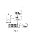
本明細書に示す実施形態は、同期機械の健全性を監視する方法及びシステムに関する。図1は、様々な実施形態が機能する環境100を示す。環境100は、同期機械102と、励磁器制御装置104と、監視ユニット106と、同期機械健全性監視システム108と、データ記憶装置110とを含む。
The embodiments presented herein relate to a method and system for monitoring the health of a synchronous machine. FIG. 1 illustrates an
同期機械102は、回転磁界の回転速度と同じ速度でロータが回転する電気機械エネルギー変換装置である。例示的な同期機械には、同期発電機、同期モータ、及び力率補正器がある。同期機械102は、電気的接続を変更することによってモータリングモードと発電モードの間で切り換わる。例えば、航空ガスタービンエンジンでは、同期機械102は始動発電機である。同期機械102は、オンボードバッテリからの電気エネルギーを受け入れてガスタービンエンジンを始動させるモータリングモードで作動する。ガスタービンエンジンが始動すると、制御電子装置は、ガスタービンエンジン軸からの機械エネルギーを受け入れ、航空機用の電力を発生させる発電モードに同期機械102を切り換える。同期機械102は、界磁巻線及び電機子巻線を含む。一般的に、低電力且つ低トルクの用途では、同期機械102は、ステータ上に配置された界磁巻線と、ロータ上に配置された電機子巻線とを含む回転電機子型である。高トルク且つ高電力を必要とする工業用途では、同期機械102は、ロータ上に配置された界磁巻線と、ステータ上に配置された電機子巻線とを含む回転磁界型である。電機子巻線は積層され、一般的に大電流を搬送する。長期にわたる使用は、積層を劣化させることがあり、巻き間の故障を引き起こす可能性がある。本明細書に示す様々な実施形態は、電機子巻線の巻き間の故障を検出するように適用される。本明細書に示す実施形態は、回転磁界型の同期機械に関して記載されているが、実施形態はあらゆる型の同期機械に等しく適用できることを理解されたい。
The
励磁器制御装置104は、界磁巻線を励磁するために、限定されないが、例えば、直流発電機、バッテリ、整流AC電源、又は静止励磁器などの励磁器を含む。静止励磁器は、変圧器、整流器、及び反応器のシステムを介して、発電機出力の各相からの一部の交流を直流励起として界磁巻線にフィードバックする。外部の直流源は、界磁巻線の初期励起に使用される。励磁器は、本明細書では界磁電圧と呼ばれる励起電圧を同期機械102の界磁巻線に印加し、それによって界磁電流を界磁巻線に流す。界磁巻線の回転によって、発電機102のステータ内に配置された固定コイルにリンクした磁束が正弦波状に変動し、固定コイルの端子全体に電圧の正弦波変動を起こす。励磁器制御装置104は、発電機102の動作を制御する。例えば、励磁器制御装置104は、発電機102に供給される界磁電圧及び界磁電流を制御する。
The
同期機械102は、励磁器制御装置104によって作動及び制御される。励磁器制御装置104には、直流(DC)電源、交流(AC)電源、及び同期機械102の動作を制御する制御システムが含まれる。制御システムは、出力時の電圧が一定のままであるように界磁巻線電圧を制御する。更に、制御システムは、同期機械102に供給される電力又は同期機械102から供給される電力を制御する。制御システムは、同期機械102の力率も制御する。励磁器制御装置104は、監視ユニット106から得た動作データに基づいて同期機械102の動作を制御する。
監視ユニット106は、同期機械102に対応する動作データを得る1つ又は複数のセンサを含む。動作データには、同期機械102の1つ又は複数の相の相電流値、相電圧値、及び同期機械の速度が含まれる。動作データには、例えば、界磁電流、入力電力、出力電力、力率を更に含んでもよい。そして、動作データは、励磁器制御装置104及び同期機械健全性監視システム108に伝達される。同期機械健全性監視システム108は、図2と関連して詳述している。
The
一実施形態において、監視ユニット106及び励磁器制御装置104は、一体型励起制御監視システムに含まれる。そのような一体型励起制御監視システムは、限定されないが、例えば、マイクロコントローラ、マイクロプロセッサ、論理回路、及びメモリなどのハードウェア、並びにメモリに保存されたソフトウェアモジュールを用いて実行する。
In one embodiment, the
環境100は、更にデータ記憶装置110から構成される。データ記憶装置110は、同期機械102の動作に対応するデータを含む。例えば、データ記憶装置110は、定格速度での正相電流及び界磁電流の関数としての同期機械102の逆相電圧(Vn)からなるルックアップテーブルを含む。データ記憶装置110は、同期機械102を構成するのに使用される磁性材料の磁化特性を更に含む。
The
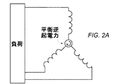
図2は、健全な電機子巻線と巻線故障を有する電機子巻線の間の回路レベルの違いを示す。図2Aは健全な電機子巻線を示し、図2Bは巻線故障を有する電機子巻線を示す。図2Bに示すように、巻線故障は磁界の非対称性を形成し、これが更に磁界の相分を形成する。磁界の相分には、正相分、逆相分及び零相分が含まれる。磁界の逆相分は、電機子巻線の逆相逆起電力(EMF)を含む。逆相分は、一般的に巻線故障のサインを伝達する。逆相逆起電力の情報を使用して、巻線故障を検出する。 FIG. 2 shows the circuit level difference between a healthy armature winding and an armature winding with winding failure. FIG. 2A shows a healthy armature winding and FIG. 2B shows an armature winding with a winding fault. As shown in FIG. 2B, the winding fault creates a magnetic field asymmetry, which further forms the phase of the magnetic field. The phase component of the magnetic field includes a normal phase component, a reverse phase component, and a zero phase component. The negative phase component of the magnetic field includes the negative phase counter electromotive force (EMF) of the armature winding. The reverse phase component generally conveys a sign of a winding failure. The information on the reverse phase counter electromotive force is used to detect a winding fault.
一般的に、逆相逆起電力は測定可能でない場合がある。本明細書に示す実施形態は、機械の健全性指標に関して表された逆相逆起電力を推定する方法を含む。上記の機械の健全性指標は、同期機械102の端子に発生する逆相電圧(Vn)に基づいて算出する。
In general, the reverse phase back electromotive force may not be measurable. The embodiments shown herein include a method for estimating a reverse-phase counter-electromotive force expressed in terms of a machine health index. The machine health index is calculated based on the reverse phase voltage (Vn) generated at the terminal of the
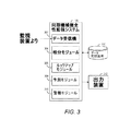
図3は、一実施形態に従った、同期機械健全性監視システム108を示す。同期機械健全性監視システム108は、同期機械102に関するデータを受信するデータ受信機302を含む。同期機械102に関するデータには、1つ又は複数の相の相電圧値及び相電流値、速度、界磁電流、電力入力、電力出力、力率等が含まれる。データ受信機302はまた、相電圧値を対応する線間電圧値に、相電流を対応する線電流に変換する。
FIG. 3 illustrates a synchronous machine
同期機械健全性監視システム108は、相電圧値及び相電流値の相分を算出する相分モジュール304を更に含む。相電圧値の相分には、正相電圧、逆相電圧(Vn)及び零相電圧が含まれる。そして、相分モジュール304は、同期機械の構成により、電圧及び電流の相分を算出する。同期機械の様々な構成は、様々な相分の巻き間故障サインを伝達する。三相三線式構成又は平衡負荷構成では、相分モジュール304は、受信した相電圧値又は線間電圧値からVnを算出する。例えば、同期機械102の三相三線式構成又は平衡負荷構成では、相分モジュール304は、逆相電圧Vnを算出する。同期機械102の不平衡負荷構成では、相分モジュール304は、Vnに加えて、逆相電流In及び逆相インピーダンスZnnを算出する。更に、同期機械102の三相四線式構成では、相分モジュール304は、Vn、In及びZnnに加えて、零相電流I0を算出する。
The synchronous machine
同期機械健全性監視システム108は、1つ又は複数の既知のVnを取り出すルックアップモジュール306を更に含む。1つ又は複数のVnの既知の値は、データ記憶装置110から得る。データ記憶装置110は、例えば、ある特定の速度での界磁電流、正相電流の関数として表にされた既知の健全なVn値を含む。このVn値は、同期機械の定格速度に対応する。既知のVnを取り出した後、ルックアップモジュールは、同期機械の計測速度に基づいて取り出したVnを測定する。同期機械のVn値及び速度は、互いに比例関係を有する。或いは、データ記憶装置110は、同期機械102の異なる速度の異なる組の既知のVn値を含む。一実施形態において、ルックアップモジュール306は、複数の相電流値に基づいて界磁電流及び正相電流を算出する演算ユニットを更に含む。正相電流は、複数の相電流値から求める。同様に、界磁電流は、同期機械102の複数の相電流値及び磁化特性に基づいて求める。磁化特性は、データ記憶装置110に保存される。ルックアップモジュール306は、界磁電流を算出するためにデータ記憶装置110から磁化特性データを取り出す。一実施形態において、既知のVnは、界磁電流及び正相電流に基づいて取り出される。
The synchronous machine
ルックアップモジュール306は、界磁電流及び正相電流を用いてデータ記憶装置110に問い合わせるクエリユニットを更に有する。クエリユニットは、1つ又は複数の既知のVn値を取り出し、Vn値には、開回路のVn及び健全状態のVnが含まれる。開回路のVnは、ルックアップテーブルからルックアップモジュール306によって算出された界磁電流に対応する開回路のVnエントリを取り出すことによって求められる。更に、健全状態のVnは、ルックアップテーブルからルックアップモジュール306によって算出された正相電流及び界磁電流に対応するVnエントリを取り出すことによって求められる。
The
上記のように、同期機械102の様々な構成は、様々な相分の巻き間故障サインを伝達する。不平衡三相構成の実施態様では、データ記憶装置110は、界磁電流及び正相電流の関数として表にされた、特定の速度の既知のIn及び既知のZnn値を追加的に含む。或いは、三相四線式構成の実施態様では、データ記憶装置110は、特定の速度の既知のVn、既知のIn、及び既知のZnn値に加えて、既知のI0を含む。ルックアップモジュール306は、既知のVnを取り出すのに説明したのと同じ技術を用いて既知のIn、既知のZn、及び既知のI0値を取り出す。
As described above, the various configurations of the
同期機械健全性監視システム108は、算出したVn及び1つ又は複数の既知のVnに基づいて機械の健全性指標を算出する予測モジュール308を更に含む。一実施形態において、機械の健全性指標は、健全状態のVnと算出したVnの間のフェーザ差を求め、開回路のVnに対してフェーザ差を正規化することによって算出する。同期機械102の健全性は、機械の健全性指標に基づいて評価される。機械の健全性指標は、特定の健全状態値を有する。予測モジュール308によって算出された機械の健全性指標が健全状態値と異なると、同期機械102の電機子の巻き間故障が示されることになる。機械の健全性指標の健全状態値は、健全な同期機械を検査することによって求められる。或いは、健全状態値は、同期機械102のモデルのシミュレーションを実行することによって求めてもよい。
The synchronous machine
システム108は、警報モジュール310を更に含む。警報モジュール310は、機械の健全性指標が健全状態値から外れると警報を発する。故障状態は、出力装置312によって示される。一実施形態において、出力装置312は、警告を表示する表示装置である。代替実施形態では、表示装置は可聴警報である。出力装置312は、更に視聴覚警報である。
様々な実施形態において、警報モジュール310は、警報を発するために統計的手法を用いる。例えば、警報モジュール310は、例えば、5分窓にわたって機械の健全性指標を監視する。そして、警報モジュール310は、5分窓の間に機械の健全性指標が健全状態値から外れた時間の比率を算出する。そして、警報モジュール310は、算出した比率に基づいて警報を発する。或いは、警報モジュール310は、限定されないが、例えば、標準偏差又は統計的平均などの統計的変動性尺度を使用してもよい。警報モジュール310は、例えば、15分窓にわたる機械の健全性指標の平均を算出する。そして、警報モジュール310は、平均を機械の健全性指標の健全状態値と比較し、平均が健全状態値から所定量外れると警報を発する。統計的手法の使用により、機械の健全性指標の一時の変動が警報を鳴らすことを防ぐことができる。これは、誤警報の削減に有効となる。
In various embodiments, the
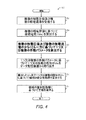
図4は、一実施形態に従った、同期機械の健全性を監視するプロセス400を示すフローチャートである。ステップ402において、複数の相電圧値及び複数の相電流値が受信される。同期機械102の動作に関するその他のデータもまた受信される。例えば、同期機械速度、電力入力、電力出力、力率などが受信される。一実施形態では、受信した相電圧値が線間電圧値に変換される。当然のことながら、線間電圧値及び相電圧値はフェーザ量であり、それらに関連した位相角を有する。従って、プロセス400は、特定の位相角を相電圧値及び相電流値の各々に関連づけることになり、相電圧値から線間電圧値を求めると共に、必要な位相シフトを取り入れなければならない。
FIG. 4 is a flowchart illustrating a
ステップ404において、Vnは相電圧値に基づいて算出される。Vnは、各々の相電圧値に適当な係数を掛けてから、各々の相電圧値のフェーザ和を取り出すことによって算出する。
In
ステップ406において、相電圧値及び相電流値に基づいて、1つ又は複数の作動パラメータが算出される。一実施形態において、1つ又は複数の作動パラメータは、線間電圧値及び線電流値に基づいて算出される。作動パラメータには、界磁電流及び正相電流が含まれる。界磁電流は、磁化特性及び相電流値に基づいて算出される。磁化特性データは、データ記憶装置110から取り出される。更に、正相電流は、同期機械102の三相に対応する相電流値に基づいて算出される。
In
ステップ408において、1つ又は複数の作動パラメータに基づいて、1つ又は複数の既知のVn値が求められる。1つ又は複数のVnの既知の値は、データ記憶装置110から求められる。データ記憶装置110は、同期機械速度の様々な異なる値に関して、界磁電流、正相電流の関数として表にされた既知のVn値を含む。データ記憶装置110は、健全な同期機械に対応する既知のVn値を更に有する。
In
Vnの既知の値には、健全状態のVn及び健全な開回路のVnが含まれる。開回路のVnは、ルックアップテーブルから、ステップ406において求めた界磁電流及び同期機械速度の受信した値に対応する開回路のVnエントリを取り出すことによって求める。更に、健全状態のVnは、ルックアップテーブルから、正相電流、ステップ406において求めた界磁電流、及び同期機械速度の受信した値に対応するVnエントリを取り出すことによって求められる。
Known values of Vn include healthy Vn and healthy open circuit Vn. The open circuit Vn is determined by retrieving from the lookup table the open circuit Vn entry corresponding to the received values of field current and synchronous machine speed determined in
一実施形態では、不平衡三相構成の予測に関して、同期機械健全性監視システム108は、追加的に既知のIn及び既知のZnn値を求める。別の実施形態では、三相四線式構成の予測に関して、同期機械健全性監視システム108は、既知のVn、既知のIn、及び既知のZnn値に加えて、既知のI0を求める。
In one embodiment, for predicting an unbalanced three-phase configuration, the synchronous machine
ステップ410において、機械の健全性指標は、算出したVn及び1つ又は複数の既知のVnに基づいて算出される。一実施形態において、機械の健全性指標は、健全状態のVnと算出したVnの間のフェーザ差を求め、開回路のVnに対してフェーザ差を正規化することによって算出する。同期機械102の健全性は、機械の健全性指標に基づいて評価する。機械の健全性指標は、特定の健全状態値を有する。予測モジュール408によって算出された機械の健全性指標が健全状態値と異なると、同期機械102の電機子の巻き間故障が推定される。
In
ステップ412において、警報は、機械の健全性指標の値に基づいて発せられる。警報は、機械の健全性指標を所定閾値と比較することによって発せられる。所定閾値は、機械の健全性指標の健全状態値である。図3に関連して説明したように、警報は、可聴警報、可視警報又は視聴覚警報である。
In
様々な実施形態において、同期機械健全性監視システム108は、コンピュータ実行可能命令として実行してもよい。システム108は、コンピュータ実行可能命令を実行する1つ又は複数の処理装置を有する。コンピュータ実行可能命令は、磁気記憶ディスク、光記憶ディスク等の固定(非一時的)コンピュータ可読媒体に組み込んでもよい。或いは、コンピュータ可読媒体は、ランダムアクセスメモリ(RAM)、読み出し専用メモリ(ROM)、書き込み可能読み出し専用メモリ(PROM)、消去書き込み可能読み出し専用メモリ(EPROM)等の1つであってよい。
In various embodiments, the synchronous machine
コンピュータプログラム製品の符号化命令には、複数の相電圧値、相電流値を受信し、複数の相電圧値及び複数の相電流値に基づいてVnを算出し、相電圧値及び相電流値に基づいて1つ又は複数の作動パラメータを算出するための命令が含まれる。作動パラメータには、界磁電流及び正相電流が含まれる。コンピュータプログラム製品は、相電圧値を線間電圧値に変換するための符号化命令を更に有する。コンピュータプログラム製品は、データ記憶装置110から開回路のVn及び健全状態のVnを取り出すための符号化命令を更に有する。コンピュータプログラム製品は、健全状態のVnと算出したVnのフェーザ差を求め、開回路のVnに対してフェーザ差を正規化することによって、機械の健全性指標を算出するための命令を更に有する。コンピュータプログラム製品はまた、機械の健全性指標を所定閾値と比較し、比較に基づいて警報を発するための符号化命令を有する。
An encoding instruction of a computer program product receives a plurality of phase voltage values and phase current values, calculates Vn based on the plurality of phase voltage values and the plurality of phase current values, Instructions for calculating one or more operating parameters based on the instructions are included. The operating parameters include field current and positive phase current. The computer program product further comprises encoding instructions for converting the phase voltage value into a line voltage value. The computer program product further comprises encoding instructions for retrieving open circuit Vn and healthy Vn from the
本明細書に記載の、界磁電流を除く電圧及び電流はフェーザ量であり、特に明記しない限り、フェーザ代数の法則に従って処理される。 The voltages and currents, excluding the field current, described herein are phasor quantities and are processed according to the laws of phasor algebra unless otherwise specified.
本明細書に記載の実施形態は、単なる例示のためのものである。当業者には、本明細書に示した教示は、記載の実施形態に限定されるものではなく、添付の特許請求の範囲の精神及び範囲によってのみ限定される修正及び変更を加えて実施することができることが、この明細書からわかるであろう。 The embodiments described herein are for illustrative purposes only. It will be apparent to those skilled in the art that the teachings presented herein are not limited to the embodiments described but are practiced with modification and alteration limited only by the spirit and scope of the appended claims. It will be appreciated from this specification that
Claims (10)
複数の相電圧値及び複数の相電流値を受信するステップ(402)と、
前記複数の相電圧値に基づいて、同期機械の巻線故障のサインを伝達する逆相逆起電力(EMF)を表す逆相電圧(Vn)を算出するステップ(404)と、
前記複数の相電圧値及び前記複数の相電流値の少なくとも一方に基づいて1つ又は複数の作動パラメータを算出するステップ(406)と、
前記1つ又は複数の作動パラメータに基づいて1つ又は複数の既知のVnをデータ記憶装置から取り出すステップ(408)と、
前記算出したVnと、前記同期機械の計測速度に従って測定される前記1つ又は複数の既知のVnに基づいて機械の健全性指標を算出するステップ(410)と、
前記機械の健全性指標に基づいて警報を発するステップ(412)とを含む、方法。 A method for monitoring the health of a synchronous machine,
Receiving (402) a plurality of phase voltage values and a plurality of phase current values;
Calculating a negative phase voltage (Vn) representing a negative phase counter electromotive force (EMF) that conveys a sign of a winding failure of the synchronous machine based on the plurality of phase voltage values;
Calculating one or more operating parameters based on at least one of the plurality of phase voltage values and the plurality of phase current values;
Retrieving (408) one or more known Vn from the data storage device based on the one or more operating parameters;
Calculating a machine health index based on the calculated Vn and the one or more known Vn measured according to the measurement speed of the synchronous machine;
Issuing an alarm based on a health indicator of the machine (412).
前記1つ又は複数の作動パラメータに基づいて1つ又は複数の既知のIn、及び1つ又は複数の既知のZnnをデータ記憶装置から取り出すステップと、
前記算出したIn、前記算出したZnn、前記1つ又は複数の既知のIn、及び前記1つ又は複数の既知のZnnを考慮して、前記機械の健全性指標を算出するステップとを更に含む、請求項1に記載の方法。 Calculating a negative phase current (In) and a negative phase impedance (Znn) based on the plurality of phase voltage values and the plurality of phase current values;
Retrieving from the data storage device one or more known In and one or more known Znn based on the one or more operating parameters;
Calculating the machine health index in consideration of the calculated In, the calculated Znn, the one or more known In, and the one or more known Znn; The method of claim 1.
前記1つ又は複数の作動パラメータに基づいて1つ又は複数の既知のI0をデータ記憶装置から取り出すステップと、
前記算出したI0及び前記1つ又は複数の既知のI0を考慮して、前記機械の健全性指標を算出するステップとを更に含む、請求項2に記載の方法。 Calculating a zero phase current (I0) based on the plurality of phase current values;
Retrieving one or more known I0s from a data storage device based on the one or more operating parameters;
The method of claim 2, further comprising: calculating a soundness index of the machine taking into account the calculated I0 and the one or more known I0s.
複数の相電圧値及び複数の相電流値を受信するデータ受信機(302)と、
前記複数の相電圧値に基づいて、同期機械の巻線故障のサインを伝達する逆相逆起電力(EMF)を表す逆相電圧(Vn)を算出する相分モジュール(304)と、
前記複数の相電圧値及び前記複数の相電流値の少なくとも一方に基づいて1つ又は複数の既知のVnをデータ記憶装置から取り出すルックアップモジュール(306)と、
前記算出したVnと、前記同期機械の計測速度に従って測定される前記1つ又は複数の既知のVnに基づいて機械の健全性指標を算出する予測モジュール(308)と、
前記機械の健全性指標に基づいて警報を発する警報モジュール(310)とを含む、システム。 A system for monitoring the health of a synchronous machine,
A data receiver (302) for receiving a plurality of phase voltage values and a plurality of phase current values;
A phase split module (304) for calculating a negative phase voltage (Vn) representing a negative phase counter electromotive force (EMF) for transmitting a sign of a winding failure of the synchronous machine based on the plurality of phase voltage values;
A lookup module (306) for retrieving one or more known Vn from a data storage device based on at least one of the plurality of phase voltage values and the plurality of phase current values;
A prediction module (308) for calculating a machine health index based on the calculated Vn and the one or more known Vn measured according to the measurement speed of the synchronous machine;
An alarm module (310) for generating an alarm based on the health indicator of the machine.
前記ルックアップモジュールは、更に、既知のIn、既知のZnn、及び既知のI0の少なくとも1つを更に取り出し、
前記予測モジュールは、前記算出したIn、前記算出したZnn、前記算出したI0、前記既知のIn、前記既知のZnn、及び前記既知のI0の少なくとも1つに更に基づいて前記機械の健全性指標を算出する、請求項4に記載のシステム。 The phase split module further calculates at least one of a negative phase current (In), a negative phase impedance (Znn), and a zero phase current (I0) based on the plurality of phase voltage values and the plurality of phase current values. And
The lookup module further retrieves at least one of known In, known Znn, and known I0,
The prediction module may further determine the health indicator of the machine based on at least one of the calculated In, the calculated Znn, the calculated I0, the known In, the known Znn, and the known I0. The system according to claim 4, wherein the system is calculated.
前記複数の相電流値に基づいて界磁電流及び正相電流を算出する演算ユニットと、
前記界磁電流及び前記正相電流を用いて前記データ記憶装置に問い合わせるクエリユニットとを更に含む、請求項4に記載のシステム。 The lookup module is
An arithmetic unit for calculating a field current and a positive phase current based on the plurality of phase current values;
5. The system of claim 4, further comprising a query unit that queries the data storage device using the field current and the positive phase current.
複数の相電圧値及び複数の相電流値を受信させ(402)、
前記複数の相電圧値に基づいて、同期機械の巻線故障のサインを伝達する逆相逆起電力(EMF)を表す逆相電圧(Vn)を算出させ(404)、
前記複数の相電圧値及び前記複数の相電流値の少なくとも一方に基づいて1つ又は複数の作動パラメータを算出させ(406)、
前記1つ又は複数の作動パラメータに基づいて1つ又は複数の既知のVnをデータ記憶装置から取り出させ(408)、
前記算出したVnと、前記同期機械の計測速度に従って測定される前記1つ又は複数の既知のVnに基づいて機械の健全性指標を算出させ(410)、
前記機械の健全性指標に基づいて警報を発せさせる(412)、コンピュータプログラム製品。 A computer program product comprising a fixed (non-transitory) computer-readable medium encoded with computer-executable instructions for monitoring the health of a synchronous machine, wherein the computer-executable instructions are executed at one or more processing devices. In addition,
Receiving a plurality of phase voltage values and a plurality of phase current values (402);
Based on the plurality of phase voltage values, a negative phase voltage (Vn) representing a negative phase counter electromotive force (EMF) that transmits a sign of a winding failure of the synchronous machine is calculated (404),
Calculating one or more operating parameters based on at least one of the plurality of phase voltage values and the plurality of phase current values (406);
Retrieving one or more known Vn from the data storage device based on the one or more operating parameters (408);
Calculating a health index of the machine based on the calculated Vn and the one or more known Vn measured according to the measurement speed of the synchronous machine (410);
A computer program product that causes an alarm to be generated (412) based on a health indicator of the machine.
既知のIn、既知のZnn、及び既知のI0の少なくとも1つを取り出し、
更に前記算出したIn、前記算出したZnn、前記算出したI0、前記既知のIn、前記既知のZnn、及び前記既知のI0の少なくとも1つに基づいて前記機械の健全性指標を算出する、請求項7に記載のコンピュータプログラム製品。 Calculating at least one of a negative phase current (In), a negative phase impedance (Znn), and a zero phase current (I0) based on the plurality of phase voltage values and the plurality of phase current values;
Retrieve at least one of known In, known Znn, and known I0;
The machine health index is further calculated based on at least one of the calculated In, the calculated Znn, the calculated I0, the known In, the known Znn, and the known I0. 7. The computer program product according to 7.
前記健全状態のVnと前記算出したVnの間のフェーザ差を算出させ、
前記開回路のVnに対して前記フェーザ差を正規化させるコンピュータ実行可能命令を更に含む、請求項7に記載のコンピュータプログラム製品。 The one or more processing devices;
Calculating a phasor difference between the healthy Vn and the calculated Vn;
8. The computer program product of claim 7, further comprising computer executable instructions for normalizing the phasor difference with respect to Vn of the open circuit.
Applications Claiming Priority (2)
| Application Number | Priority Date | Filing Date | Title |
|---|---|---|---|
| US12/976,309 US8803461B2 (en) | 2010-12-22 | 2010-12-22 | System and method for synchronous machine health monitoring |
| US12/976,309 | 2010-12-22 |
Publications (3)
| Publication Number | Publication Date |
|---|---|
| JP2012132909A true JP2012132909A (en) | 2012-07-12 |
| JP2012132909A5 JP2012132909A5 (en) | 2015-01-29 |
| JP6118019B2 JP6118019B2 (en) | 2017-04-19 |
Family
ID=45495623
Family Applications (1)
| Application Number | Title | Priority Date | Filing Date |
|---|---|---|---|
| JP2011271833A Active JP6118019B2 (en) | 2010-12-22 | 2011-12-13 | System and method for monitoring the health of a synchronous machine |
Country Status (6)
| Country | Link |
|---|---|
| US (1) | US8803461B2 (en) |
| EP (1) | EP2469703B1 (en) |
| JP (1) | JP6118019B2 (en) |
| CN (1) | CN102608491B (en) |
| BR (1) | BRPI1105177A2 (en) |
| CA (1) | CA2761344C (en) |
Cited By (5)
| Publication number | Priority date | Publication date | Assignee | Title |
|---|---|---|---|---|
| JP2014055952A (en) * | 2012-09-13 | 2014-03-27 | General Electric Co <Ge> | Detection of generator stator inter-circuit faults |
| KR101878810B1 (en) * | 2017-03-08 | 2018-07-16 | 엘지전자 주식회사 | Fault diagnosis method of motor |
| KR101946743B1 (en) | 2014-12-10 | 2019-02-11 | 미쓰비시덴키 가부시키가이샤 | Electric motor diagnosis device |
| KR20220056628A (en) * | 2020-10-28 | 2022-05-06 | 주식회사 위드피에스 | Synchoronous generator, apparatus and method for monitoring of synchoronous generator, computer-readable storage medium and computer program |
| WO2022149534A1 (en) | 2021-01-08 | 2022-07-14 | 日立建機株式会社 | Maintenance assistance system |
Families Citing this family (12)
| Publication number | Priority date | Publication date | Assignee | Title |
|---|---|---|---|---|
| JP5882019B2 (en) * | 2011-10-17 | 2016-03-09 | 株式会社日立製作所 | Inverter-driven rotating electrical machine testing method and rotating electrical machine testing method |
| FR3023628A1 (en) * | 2014-07-10 | 2016-01-15 | Airbus Helicopters | METHOD AND SYSTEM FOR MERGING DEVICE MONITORING INDICATORS |
| GB201616900D0 (en) | 2016-10-05 | 2016-11-16 | Rolls Royce Plc | Brushless synchronous generator stator winding fault |
| US10408879B2 (en) | 2016-10-10 | 2019-09-10 | Rolls-Royce Plc | Method and apparatus for diagnosing a fault condition in an electric machine |
| CN107171494B (en) * | 2017-06-15 | 2018-07-20 | 苏州达思灵新能源科技有限公司 | A kind of compressed air turbodynamo system |
| US10895873B2 (en) * | 2018-04-25 | 2021-01-19 | Aktiebolaget Skf | Machine health monitoring of rotating machinery |
| CN109387724B (en) * | 2018-09-30 | 2020-10-27 | 南京理工大学 | Fault diagnosis method for synchronous phase modulator based on longitudinal analysis and transverse correction |
| US11143715B2 (en) * | 2019-08-15 | 2021-10-12 | Schweitzer Engineering Laboratories, Inc. | Broken conductor detection in a multiple-phase electric power delivery system |
| JP7312670B2 (en) * | 2019-10-31 | 2023-07-21 | 株式会社日立産機システム | Rotating equipment diagnostic system and method. |
| EP4109721B1 (en) * | 2020-02-17 | 2024-01-31 | Mitsubishi Electric Corporation | Diagnostic device of permanent magnet synchronous motor, and inverter comprising said diagnostic device |
| CN111917349B (en) * | 2020-06-22 | 2022-06-28 | 广州智能装备研究院有限公司 | Fault diagnosis method and system for permanent magnet synchronous motor |
| DE102020215366A1 (en) * | 2020-12-04 | 2022-06-09 | Rolls-Royce Deutschland Ltd & Co Kg | Monitoring method and device for an electric propulsion system |
Citations (6)
| Publication number | Priority date | Publication date | Assignee | Title |
|---|---|---|---|---|
| US5514978A (en) * | 1995-03-20 | 1996-05-07 | General Electric Company | Stator turn fault detector for AC motor |
| JPH11113296A (en) * | 1997-10-02 | 1999-04-23 | Hitachi Ltd | Controller for generator motor and power generation system employing the same |
| US6141196A (en) * | 1998-03-02 | 2000-10-31 | General Electric Company | Method and apparatus for compensation of phasor estimations |
| US6144924A (en) * | 1996-05-20 | 2000-11-07 | Crane Nuclear, Inc. | Motor condition and performance analyzer |
| US20100194323A1 (en) * | 2009-02-03 | 2010-08-05 | General Electric Company | Robust on line stator turn fault identification system |
| US20100194324A1 (en) * | 2009-02-03 | 2010-08-05 | General Electric Company | Stator turn fault detection apparatus and method for induction machine |
Family Cites Families (17)
| Publication number | Priority date | Publication date | Assignee | Title |
|---|---|---|---|---|
| US3723718A (en) | 1970-11-09 | 1973-03-27 | Syst De Corp | Simulation through rotating coordinate transformation |
| SU1591660A1 (en) * | 1988-03-22 | 1991-11-30 | Do Politekh Inst | Method of determining inductive leakage reactance of three-phase synchronic machine |
| US4937530A (en) * | 1988-07-19 | 1990-06-26 | Siemens Aktiengesellschaft | Apparatus for monitoring phase voltages of a polyphase tachometer generator to detect phase failures |
| US5252915A (en) * | 1992-01-23 | 1993-10-12 | Ontario Hydro | Method and apparatus for detecting stator faults in rotary dynamoelectric machines |
| US5270640A (en) * | 1992-04-23 | 1993-12-14 | The Penn State Research Foundation | Method for incipient failure detection in electric machines |
| US5345158A (en) * | 1992-10-02 | 1994-09-06 | General Electric Company | Electrical distribution equipment with torque estimating capability |
| US5612601A (en) * | 1993-11-22 | 1997-03-18 | Martin Marietta Energy Systems, Inc. | Method for assessing motor insulation on operating motors |
| US5477163A (en) * | 1994-08-03 | 1995-12-19 | General Electric Company | Turn fault detection |
| US5786708A (en) * | 1996-04-01 | 1998-07-28 | General Electric Company | Self-tuning and compensating turn fault detector |
| US20050218906A1 (en) * | 2004-03-31 | 2005-10-06 | Younsi Abdelkrim K | System and method for monitoring of insulation condition |
| ITVA20040055A1 (en) | 2004-11-23 | 2005-02-23 | St Microelectronics Srl | METHOD AND CIRCUIT OF CONTROL OF AN ELECTRICITY GENERATION SYSTEM |
| CN101091295B (en) | 2005-12-09 | 2011-04-13 | Abb技术有限公司 | Method and device for fault detection in an n-winding three-phase power transformer |
| CN101087093B (en) * | 2007-06-08 | 2011-01-12 | 哈尔滨工业大学 | Synchronization electromotor with detection coil |
| ATE479103T1 (en) * | 2007-07-19 | 2010-09-15 | Abb Research Ltd | METHOD FOR ERROR DETECTION IN UNCOMPENSATED POWER LINES WITH UNSYNCHRONIZED TWO-END MEASUREMENT |
| JP4458174B2 (en) | 2008-03-21 | 2010-04-28 | 株式会社デンソー | Rotating machine control device and rotating machine control system |
| CN101556307B (en) * | 2009-03-11 | 2011-07-06 | 东北大学 | Permanent magnet synchronous motor control performance automation test system |
| CN101603997B (en) * | 2009-07-03 | 2011-03-30 | 哈尔滨工业大学 | Method for testing parameters of synchronous motor and device for achieving same |
-
2010
- 2010-12-22 US US12/976,309 patent/US8803461B2/en active Active
-
2011
- 2011-12-07 BR BRPI1105177-9A patent/BRPI1105177A2/en not_active Application Discontinuation
- 2011-12-07 EP EP11192364.5A patent/EP2469703B1/en active Active
- 2011-12-08 CA CA2761344A patent/CA2761344C/en not_active Expired - Fee Related
- 2011-12-13 JP JP2011271833A patent/JP6118019B2/en active Active
- 2011-12-22 CN CN201110461564.1A patent/CN102608491B/en active Active
Patent Citations (8)
| Publication number | Priority date | Publication date | Assignee | Title |
|---|---|---|---|---|
| US5514978A (en) * | 1995-03-20 | 1996-05-07 | General Electric Company | Stator turn fault detector for AC motor |
| US6144924A (en) * | 1996-05-20 | 2000-11-07 | Crane Nuclear, Inc. | Motor condition and performance analyzer |
| JPH11113296A (en) * | 1997-10-02 | 1999-04-23 | Hitachi Ltd | Controller for generator motor and power generation system employing the same |
| US6141196A (en) * | 1998-03-02 | 2000-10-31 | General Electric Company | Method and apparatus for compensation of phasor estimations |
| US20100194323A1 (en) * | 2009-02-03 | 2010-08-05 | General Electric Company | Robust on line stator turn fault identification system |
| US20100194324A1 (en) * | 2009-02-03 | 2010-08-05 | General Electric Company | Stator turn fault detection apparatus and method for induction machine |
| WO2010090890A1 (en) * | 2009-02-03 | 2010-08-12 | General Electric Company | Robust on line stator turn fault identification system |
| WO2010090861A2 (en) * | 2009-02-03 | 2010-08-12 | General Electric Company | Improved stator turn fault detection apparatus and method for induction machine |
Cited By (7)
| Publication number | Priority date | Publication date | Assignee | Title |
|---|---|---|---|---|
| JP2014055952A (en) * | 2012-09-13 | 2014-03-27 | General Electric Co <Ge> | Detection of generator stator inter-circuit faults |
| KR101946743B1 (en) | 2014-12-10 | 2019-02-11 | 미쓰비시덴키 가부시키가이샤 | Electric motor diagnosis device |
| KR101878810B1 (en) * | 2017-03-08 | 2018-07-16 | 엘지전자 주식회사 | Fault diagnosis method of motor |
| KR20220056628A (en) * | 2020-10-28 | 2022-05-06 | 주식회사 위드피에스 | Synchoronous generator, apparatus and method for monitoring of synchoronous generator, computer-readable storage medium and computer program |
| KR102425497B1 (en) | 2020-10-28 | 2022-07-27 | 주식회사 위드피에스 | Synchoronous generator, apparatus and method for monitoring of synchoronous generator, computer-readable storage medium and computer program |
| WO2022149534A1 (en) | 2021-01-08 | 2022-07-14 | 日立建機株式会社 | Maintenance assistance system |
| KR20230049125A (en) | 2021-01-08 | 2023-04-12 | 히다찌 겐끼 가부시키가이샤 | maintenance support system |
Also Published As
| Publication number | Publication date |
|---|---|
| CN102608491A (en) | 2012-07-25 |
| US8803461B2 (en) | 2014-08-12 |
| CA2761344A1 (en) | 2012-06-22 |
| BRPI1105177A2 (en) | 2013-04-24 |
| JP6118019B2 (en) | 2017-04-19 |
| EP2469703A3 (en) | 2017-02-01 |
| CA2761344C (en) | 2019-01-15 |
| CN102608491B (en) | 2016-04-20 |
| EP2469703B1 (en) | 2020-09-23 |
| EP2469703A2 (en) | 2012-06-27 |
| US20120161684A1 (en) | 2012-06-28 |
Similar Documents
| Publication | Publication Date | Title |
|---|---|---|
| JP6118019B2 (en) | System and method for monitoring the health of a synchronous machine | |
| Faiz et al. | Eccentricity fault detection–From induction machines to DFIG—A review | |
| US10042011B2 (en) | Method to detect or monitor the demagnetization of a magnet | |
| Shah et al. | Stator-interturn-fault detection of doubly fed induction generators using rotor-current and search-coil-voltage signature analysis | |
| US8278883B2 (en) | Load angle measurement and pole slip detection | |
| EP3480610B1 (en) | Diagnosing a winding set of a stator | |
| EP2942867B1 (en) | Induction motor speed estimation | |
| Rosero et al. | On the short-circuiting fault detection in a PMSM by means of stator current transformations | |
| CN105891660B (en) | A kind of detection method of generator unit stator winding interturn short-circuit failure | |
| EP3214757A1 (en) | Electrical machine component failure detection apparatus and method | |
| Xu et al. | A novel diagnostic method for single and dual power switch open-circuit faults of six-phase FTPMSM system even in fault tolerant operation | |
| CN106501665B (en) | Hydraulic generator rotor winding interturn short-circuit diagnostic method based on detection coil | |
| Li et al. | PMSM current sensor FDI based on DC link current estimation | |
| Bechkaoui et al. | Open-circuit and inter-turn short-circuit detection in PMSG for wind turbine applications using fuzzy logic | |
| Kechida et al. | Fault detection of broken rotor bars using stator current spectrum for the direct torque control induction motor | |
| Lee et al. | Diagnosis of interturn short-circuit fault in PMSM by residual voltage analysis | |
| Sellami et al. | Impact of inter-turn short-circuit fault on wind turbine driven squirrel-cage induction generator systems | |
| KR102212084B1 (en) | Fault diagnosis method of synchronous motor | |
| Sellami et al. | Sliding mode observers-based fault detection and isolation for wind turbine-driven induction generator | |
| Wei et al. | Rotating rectifier fault detection method of wound‐rotor synchronous starter‐generator with three‐phase exciter | |
| Praneeth et al. | Algorithm for prediction and control of induction motor stator interturn faults in electric vehicles | |
| Kral et al. | Condition monitoring and fault detection of electric drives | |
| Bouslimani et al. | An extended Park's vector approach to detect broken bars faults in Induction Motor | |
| Zeng et al. | A new method to estimate the severity of interturn short-circuit fault for PMSM | |
| Leboeuf et al. | Fault detection in a current controlled PM drive using back-EMF estimation and residual analysis |
Legal Events
| Date | Code | Title | Description |
|---|---|---|---|
| A521 | Request for written amendment filed |
Free format text: JAPANESE INTERMEDIATE CODE: A523 Effective date: 20141210 |
|
| A621 | Written request for application examination |
Free format text: JAPANESE INTERMEDIATE CODE: A621 Effective date: 20141210 |
|
| A977 | Report on retrieval |
Free format text: JAPANESE INTERMEDIATE CODE: A971007 Effective date: 20151022 |
|
| A131 | Notification of reasons for refusal |
Free format text: JAPANESE INTERMEDIATE CODE: A131 Effective date: 20151110 |
|
| A521 | Request for written amendment filed |
Free format text: JAPANESE INTERMEDIATE CODE: A523 Effective date: 20160125 |
|
| A131 | Notification of reasons for refusal |
Free format text: JAPANESE INTERMEDIATE CODE: A131 Effective date: 20160628 |
|
| A521 | Request for written amendment filed |
Free format text: JAPANESE INTERMEDIATE CODE: A523 Effective date: 20160923 |
|
| TRDD | Decision of grant or rejection written | ||
| A01 | Written decision to grant a patent or to grant a registration (utility model) |
Free format text: JAPANESE INTERMEDIATE CODE: A01 Effective date: 20170228 |
|
| A61 | First payment of annual fees (during grant procedure) |
Free format text: JAPANESE INTERMEDIATE CODE: A61 Effective date: 20170324 |
|
| R150 | Certificate of patent or registration of utility model |
Ref document number: 6118019 Country of ref document: JP Free format text: JAPANESE INTERMEDIATE CODE: R150 |
|
| R250 | Receipt of annual fees |
Free format text: JAPANESE INTERMEDIATE CODE: R250 |