JP2012132591A - Refrigerator - Google Patents
Refrigerator Download PDFInfo
- Publication number
- JP2012132591A JP2012132591A JP2010283388A JP2010283388A JP2012132591A JP 2012132591 A JP2012132591 A JP 2012132591A JP 2010283388 A JP2010283388 A JP 2010283388A JP 2010283388 A JP2010283388 A JP 2010283388A JP 2012132591 A JP2012132591 A JP 2012132591A
- Authority
- JP
- Japan
- Prior art keywords
- humidity control
- humidity
- control member
- refrigerator
- types
- Prior art date
- Legal status (The legal status is an assumption and is not a legal conclusion. Google has not performed a legal analysis and makes no representation as to the accuracy of the status listed.)
- Granted
Links
Images


Landscapes
- Devices That Are Associated With Refrigeration Equipment (AREA)
- Cold Air Circulating Systems And Constructional Details In Refrigerators (AREA)
Abstract
Description
本発明は、貯蔵室内の湿度を調整可能な調湿手段を有する冷蔵庫に関する。 The present invention relates to a refrigerator having humidity control means capable of adjusting humidity in a storage chamber.
野菜などの青果物を高品質に保存するためには、温度に加えて、湿度を制御することが有効である。青果物の多くは、水分を90%以上含んでおり、その約5%を失うと、商品価値がないといわれている。蒸散作用による水分喪失は、重量減少、しなび、など品質低下の原因となる。したがって、蒸散作用を抑制することが、鮮度保持において重要となり、野菜の蒸散作用を抑制するためには、高湿度環境での保存が望ましい。 In order to preserve fruits and vegetables such as vegetables with high quality, it is effective to control humidity in addition to temperature. Many fruits and vegetables contain 90% or more of water, and if it loses about 5%, it is said that there is no commercial value. Moisture loss due to transpiration can cause quality degradation such as weight loss and shrimp. Therefore, suppressing transpiration is important in maintaining freshness, and in order to suppress transpiration of vegetables, storage in a high humidity environment is desirable.
一方で、貯蔵室内の結露を抑制する必要がある。扉開閉などにより流入した外気が冷却されて貯蔵室内に結露を生じ、結露した水滴が落下し、青果物に接触すると、腐敗を生じる場合がある。また、食品を一度に大量に収容することなどにより、貯蔵室内の湿度が著しく上昇した場合にも、同様に結露する可能性がある。 On the other hand, it is necessary to suppress condensation in the storage chamber. The outside air that has flowed in by opening or closing the door is cooled, causing condensation in the storage chamber, and if the condensed water drops fall and come into contact with the fruits and vegetables, they may rot. In addition, condensation may occur in the same manner when the humidity in the storage chamber is significantly increased by storing a large amount of food at one time.
このような背景のもとに、食品保存に最適な湿度にコントロールし、かつ結露を抑制するものとして、従来より、調湿材を用いた湿度制御が提案されている。例えば、貯蔵容器と蓋とから成る密閉性を高めた貯蔵室の内部に、高い吸放湿性を有する調湿部材を配設し、水分を吸放湿性部材に保持させ、保持した水分を室内湿度低下時に放湿させることによって、湿度を保つようにしたものがある(例えば、特許文献1参照)。 Against this background, humidity control using a humidity control material has been conventionally proposed as a means for controlling humidity to be optimal for food preservation and suppressing condensation. For example, a humidity control member having a high moisture absorption / release property is arranged inside a storage chamber made of a storage container and a lid, which has improved airtightness, and moisture is held by the moisture absorption / release material. There is one in which the humidity is kept by letting it release when it drops (see, for example, Patent Document 1).
また、野菜室内の湿度調整を、湿度増加に伴って水分透過率が大になる調湿膜を用いて行うことにより、野菜室内を常に結露のない適度な高湿状態に保つことができるようにしたものもある(例えば、特許文献2参照)。 In addition, by adjusting the humidity in the vegetable compartment using a humidity control film that increases the moisture permeability as the humidity increases, the vegetable compartment can always be kept in a moderately high humidity state without condensation. (For example, refer patent document 2).
しかしながら、前述のように一種類の調湿部材や一種類の調湿膜を用いて湿度調整を行うようにしたものにあっては、調湿部材や調湿膜のもつ吸放湿性能で、貯蔵室内の湿度が限定されてしまう。近年、冷蔵庫に保存される食品は多様化しており、それに伴い、保存する食品に合わせた湿度制御が必要となっている。従来技術では、調整される湿度が限定されるため、食品ごとに合わせて湿度を変化させることができず、食品によっては最適な湿度環境での保存ができないという問題点があった。 However, in the case where the humidity is adjusted using one type of humidity control member or one type of humidity control film as described above, the moisture absorption / release performance of the humidity control member or humidity control film is The humidity in the storage room is limited. In recent years, foods stored in refrigerators have been diversified, and accordingly, humidity control according to the foods to be stored has become necessary. In the prior art, since the humidity to be adjusted is limited, there is a problem that the humidity cannot be changed according to each food, and depending on the food, it cannot be stored in an optimum humidity environment.
本発明は、前述のような問題を解決するためになされたものであり、貯蔵室内の湿度調整が可能である冷蔵庫を提供することを目的とする。 The present invention has been made to solve the above-described problems, and an object of the present invention is to provide a refrigerator capable of adjusting the humidity in the storage chamber.
本発明に係る冷蔵庫は、扉を備え、食品を保存する貯蔵室と、貯蔵室を冷却する冷却手段と、異なる吸放湿性能を有し、貯蔵室内に設けられて選択使用される複数種の調湿部材と、複数種の調湿部材の中から使用する調湿部材を選択するための調湿部材選択手段と、を備えるものである。 The refrigerator according to the present invention is provided with a door, a storage room for storing food, a cooling means for cooling the storage room, and different moisture absorption and desorption performances. A humidity control member and a humidity control member selection means for selecting a humidity control member to be used from a plurality of types of humidity control members are provided.
本発明の冷蔵庫によれば、異なる吸放湿性能を有する複数種の調湿部材の中から使用する調湿部材を選択して使用する。これにより、貯蔵室内に保存される食品に合わせて、貯蔵室内の湿度を調節することができ、食品を最適な湿度環境で高品質に保存することができる。 According to the refrigerator of the present invention, the humidity control member to be used is selected and used from a plurality of types of humidity control members having different moisture absorption / release performances. Thereby, according to the food preserve | saved in a storage chamber, the humidity in a storage chamber can be adjusted and a foodstuff can be preserve | saved with high quality in the optimal humidity environment.
以下、図示実施形態により本発明を説明する。 The present invention will be described below with reference to illustrated embodiments.
実施形態1.
図1は本発明の実施形態1に係る冷蔵庫の正面図である。
本発明の実施形態1に係る冷蔵庫1は、図1のように複数の貯蔵室、例えば冷蔵室100、切替室200、製氷室300、冷凍室400、及び野菜室500を有している。そのうち、冷蔵室100は、最上部に開閉扉を備えて配置されている。切替室200は、引き出し扉を備え、冷蔵室100の下方に配置されて、冷凍温度帯(−18℃)から冷蔵(3℃)、チルド(0℃)、ソフト冷凍(−7℃)などの各温度帯に切り替え可能となっている。製氷室300は、引き出し扉を備え、切替室200と並列に配置されている。冷凍室400は、引き出し扉を備え、切替室200と製氷室300の下方に配置されている。野菜室500は、引き出し扉を備え、最下部に配置されている。また、冷蔵室100の扉表面には、各室の温度や設定を調節する操作スイッチと、各室の温度などを表示する液晶表示部などから構成される操作パネル6が設けられている。なお、操作パネル6は冷蔵庫の中、例えば冷蔵室の側面に設置されていても構わない。
FIG. 1 is a front view of a refrigerator according to
The
図2は本発明の実施形態1に係る冷蔵庫1の側面視の断面図である。
本発明の実施形態1に係る冷蔵庫1は、図2のように背面側に、圧縮機2、冷却器3、冷却器3により冷却された冷気を冷蔵庫内の各部屋へ送風する送風ファン4、及び冷却器3により冷却された冷気を各部屋へ導入するための風路5が設けられている。冷却器3で冷却された冷気は風路5を通り、冷凍室400、切替室200、製氷室300、冷蔵室100へと送風され、各部屋を冷却する。野菜室500は、冷蔵室100の戻り冷気を野菜室用帰還風路5aより循環させることで冷却されるようになっている。そして、野菜室500を冷却した冷気は、野菜室用帰還風路5aより冷却器3に戻されるようになっている。各部屋の温度は、各部屋に設置された図示しないサーミスタにより検知され、予め設定された温度になるように、風路5に設置された図示しないダンパの開度や圧縮機2の出力および送風ファン4の送風量を調整することで制御される。
FIG. 2 is a cross-sectional view of the
The
図2に示すように、切替室200には収納ケース201が設置されており、食品を収納することができる。冷凍室400にも収納ケース401が設置されており、食品を収納することができる。野菜室500にも同様に収納ケース501が設置されており、食品を収納することができる。なお、収納ケースの数は1個でもよいが、冷蔵庫全体の容量からして整理性などが向上する場合には2個以上あっても構わない。
As shown in FIG. 2, a
図3及び図4はいずれも本発明の実施形態1に係る冷蔵庫1の野菜室500部分を拡大して示す側面視の断面図である。野菜室500には、図3及び図4のように開閉可能な扉10と、扉10の開閉と連動して引き出される収納ケース501が設置され、扉10の開閉を検知する扉開閉検知スイッチ11が設けられている。また、野菜室500内の背面側には、野菜室500内の温度を検知するサーミスタ12と、湿度検知可能な湿度センサー9とが設置されている。また、野菜室500の天井面には、例えばプレート状の複数種の調湿部材7a,7bが野菜室内に臨む(露出する)ように設けられ、さらに複数種の調湿部材7a,7bの配置領域を部分的に覆うように、調湿部材選択手段であるスライド式のシャッター8が設けられた構成になっている。
3 and 4 are both side sectional views of the
図5は本発明の実施形態1に係る冷蔵庫1の調湿部材とシャッターの一例を示す概略構成図である。調湿部材7a,7bは、それぞれ湿気の吸放出性能が異なる材質から構成され、同一面内で配置されて矩形プレート状に形成されている。矩形プレート状の調湿部材7a,7bを部分的に覆うことができるシャッター8は、図5のように横方向にスライド動作することで、調湿部材7aと調湿部材7bの野菜室500内に露出する面積を変化させ、これによって野菜室500内の湿度を調節する機能を持っている。
FIG. 5 is a schematic configuration diagram illustrating an example of the humidity control member and the shutter of the
例えば、調湿部材7aは、野菜室500内の湿度を90〜95%に保つことができ、調湿部材7bは、野菜室500内の湿度を40〜50%に保つことができるように、多孔質材料や高分子吸収体などの材料から形成されている。
For example, the
したがって、シャッター8をスライド動作させ、調湿部材7aを全開、調湿部材7bをシャッター8によって閉鎖した場合、野菜室500は、調湿部材7aにより、湿度90〜95%に保たれる。
Therefore, when the
また、調湿部材7bを全開、調湿部材7aをシャッター8によって閉鎖した場合、野菜室500は、調湿部材7bにより、湿度40〜50%に保たれる。
When the
また、シャッター8をスライド動作させ、図4及び図5のように調湿部材7aと調湿部材7bを半開ずつとした場合、野菜室500は、湿度65〜70%に保つことができる。
Moreover, when the
このように、異なる吸放湿性能の調湿部材を組み合わせることにより、野菜室500は、複数の湿度帯に設定可能となる。蒸散作用の大きい野菜類、例えば葉菜類の場合は、高湿度環境で保存し、蒸散作用を抑制することが鮮度保持に有効である。したがって、収容物が葉菜類の場合は、野菜室500を、湿度90〜95%に保つように、シャッター8をスライド動作させて、調湿部材7aが全開になるように調節する。
In this way, the
また、かぼちゃ、にんにく、タマネギなどの根菜類は、湿度が高すぎると、腐敗しやすいため、湿度70%程度が最適な保存湿度であることが知られている。したがって、収容物が根菜類の場合は、野菜室500を、湿度65〜70%に保つように、シャッター8をスライド動作させて、調湿部材7aと調湿部材7bが半開ずつになるように調節する。
In addition, root vegetables such as pumpkin, garlic, and onion are susceptible to spoilage when the humidity is too high, and therefore it is known that the optimum storage humidity is about 70%. Therefore, when the contents are root vegetables, the
また、青果物以外のペットボトルなどを保存する場合は、表面に結露すると衛生的に好ましくないため、野菜室500を結露しない湿度40〜50%に保つように、シャッター8をスライド動作させて、調湿部材7bのみが全開になるように調節する。
Also, when storing PET bottles other than fruits and vegetables, it is not hygienically desirable to condense on the surface. Therefore, the
このように、収容物に応じた保存湿度帯を選択可能とすることにより、野菜室500は最適な保存を実現することができる。
Thus, the
野菜室500の湿度帯は、ユーザーが操作パネル6により、選択してもよい。操作パネル6上には、湿度「高」「中」「低」が選択可能な湿度調整ボタンを設け、ユーザーがボタンを押すことにより、野菜室500内の湿度を選択できるようにする。また、操作パネル6上に、「葉菜モード」「根菜モード」「その他モード」を設け、それぞれ、湿度90〜95%、湿度65〜70%、湿度40〜50%に対応させてもよい。
The humidity zone of the
また、野菜室500内に設けた湿度センサー9により、自動で判断させて野菜室500内の湿度を制御させるようにしてもよい。例えば、湿度センサー9からの出力の経時変化より、野菜室500内に収納された食品を推定し、野菜室500内の湿度を調整することができる。
Further, the
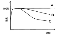
図6は本発明の実施形態1に係る冷蔵庫1の野菜室500における収容物による湿度の経時的変化のパターンを示したグラフである。野菜室500に、蒸散作用の大きい野菜(例えば、ホウレン草などの葉菜類)が収納されている場合は、図6中の線Aのように、野菜室500内の湿度は低下せず、100%RHに到達したまま低下しない。このとき、野菜の蒸散作用を抑制することが鮮度保持には必要である。この場合、野菜室500は、高湿度保存とすることが最適である。そのため、シャッター8をスライド動作させて、調湿部材7aを野菜室内に露出させる。
FIG. 6 is a graph showing a pattern of change with time of humidity by the contents in the
収納物が蒸散作用の小さい野菜(例えば、かぼちゃ、にんにく、タマネギなどの根菜類)である場合は、図6中の線Bのように、野菜室500内の湿度は、一時的に高湿状態となるが、時間経過とともに、徐々に湿度が低下する。この場合は、シャッター8をスライド動作させて、調湿部材7aと調湿部材7bが半開ずつになるように、つまり調湿部材7aと調湿部材7bが半分ずつ野菜室内に露出するように調節する。
When the stored item is a vegetable having a small transpiration effect (for example, root vegetables such as pumpkin, garlic, onion, etc.), the humidity in the
また、収納物が蒸散作用のないもの(例えば、ペットボトルなど青果物以外)である場合、図6中の線Cのように、野菜室500内の湿度は、一時的に高湿状態となるが、すぐに湿度が低下する。この場合は、シャッター8をスライド動作させて、調湿部材7bを野菜室内に露出させる。
In addition, when the stored item has no transpiration (for example, other than fruits and vegetables such as a plastic bottle), the humidity in the
扉開閉直後は、温度の高い外気が流入して冷却されるため、野菜室500内は高湿度状態となる。このとき、結露することを防止するため、扉開閉検知スイッチ11により扉の開閉が検知されたとき(例えば直後)は、野菜室500内を一旦低湿度に設定することが望ましく、調湿部材7bを野菜室内に露出させるとよい。
Immediately after the door is opened and closed, high temperature outside air flows in and cools, so the
図7は本発明の実施形態1に係る冷蔵庫1の制御部の構成を示すブロック図、図8は本発明の実施形態1に係る冷蔵庫1の運転制御動作を示すフローチャートである。次に、本発明の実施形態1に係る冷蔵庫1の運転制御の一例(湿度設定処理)の動作について図8のフローチャートに基づき、図7の制御部のブロック図を参照しながら説明する。
まず、制御装置20は、扉開閉検知スイッチ11により野菜室500の扉10の開放が検知され(ステップS101)、その後、扉10が閉じられたことが検知されると(ステップS102)、シャッター8を駆動させて、調湿部材7bを野菜室内に全露出させる(ステップS103)。次いで、制御装置20は、所定時間(例えば、2時間)経過したか否かをみて(ステップS104)、2時間経過していれば、湿度センサー9により、湿度αを検知する(ステップS105)。次いで、制御装置20は、検知された湿度αが、予め設定された湿度α1(例えばα1=95%RHに設定)より高いか否かをみる(ステップS106)。制御装置20は、ステップS106にて湿度αが湿度α1よりも高いと判断すると、シャッター8を駆動(スライド)させて、調湿部材7aを野菜室内に全露出させ(ステップS107)、処理を終了する。
FIG. 7 is a block diagram showing the configuration of the control unit of the
First, the
また、制御装置20は、ステップS106にて湿度αが湿度α1よりも低いと判断すると、検知された湿度αが予め設定された湿度α2(例えばα2=70%RHに設定)より高いか否かをみる(ステップS108)。制御装置20は、ステップS108にて湿度αが湿度α2よりも高いと判断すると、シャッター8を駆動(スライド)させて、調湿部材7aと調湿部材7bが半分ずつ野菜室内に露出するように調節し(ステップS109)、処理を終了する。
If
また、制御装置20は、ステップS108にて湿度αが湿度α2よりも低いと判断すると、調湿部材7bを野菜室内に全露出させたままとし、処理を終了する。
If the
図9は調湿部材7a,7bとシャッター8の変形例を示す概略構成図である。図3乃至図5では、調湿部材7a,7bを矩形プレート状に形成し、シャッター8が横方向にスライド動作する方式のものを例に挙げて説明したが、スライド式はこれに限るものでなく、図9のように回転方向にスライド動作する構成でもよい。すなわち、調湿部材7a,7bを同一面内で配置されて円盤状(円形プレート状)に形成するとともに、シャッター8を前記円盤の半円を覆うことができる半円状に形成して、シャッター8を回転方向にスライド動作させることにより、調湿部材7aと調湿部材7bの野菜室500内に露出する面積を変化させる。これにより、野菜室500内の湿度が調節可能となる。
FIG. 9 is a schematic configuration diagram showing a modified example of the
また、図3乃至図5の例や図9の例においては、シャッター8がスライド動作するものを例に挙げて説明したが、これに限ったものではなく、調湿部材7a,7b側を可動させる構成としてもよい。いずれにせよ、スライド機構にすることにより、動作のために必要なスペースを小さくでき、野菜室500内の収納容量を確保することが容易となる。
Further, in the examples of FIGS. 3 to 5 and FIG. 9, the
実施形態2.
図10は本発明の実施形態2に係る冷蔵庫の野菜室部分の側断面図、図11及び図12は図10におけるA−A断面図である。なお、前述の実施形態1と同じ機能部分にはこれと同じ符号を付して、一部の説明を省略する。
10 is a side sectional view of the vegetable compartment portion of the refrigerator according to the second embodiment of the present invention, and FIGS. 11 and 12 are AA sectional views in FIG. The same functional parts as those in the first embodiment are denoted by the same reference numerals, and a part of the description is omitted.
本発明の実施形態2に係る冷蔵庫は、図10のように野菜室500の背面に、複数種の調湿部材7a,7bが配置されている。複数種の調湿部材7a,7bは、図11及び図12のように軸14の周りの周方向に順次配置されて側面の一部(例えば半分)が前記貯蔵室内に露出する円柱状に形成されている。そして、複数種の調湿部材7a,7bは、調湿部材選択手段である回転機構、すなわちモーター13に接続された円柱の軸14を回転軸として回転し、野菜室500内に露出する面積を調整できるようになっている。
In the refrigerator according to
図11及び図12のように円柱が回転することにより、調湿部材7a,7bの野菜室500内に露出する面積を変化させることができ、野菜室500内の湿度を調整することができる。例えば、図11のように、円柱を90度回転させれば、調湿部材7aと調湿部材7bを半開ずつとすることができる。このように、調湿部材選択手段を回転機構(モーター13)で構成し、モーター13からの回転を円柱の回転に伝達することで、調湿部材7a,7bの野菜室500内に露出する面積を調節することができ、動力伝達を簡単な構成で実現することができる。
As shown in FIGS. 11 and 12, by rotating the cylinder, the area exposed to the
なお、前述の実施形態1,2では、回転方式の調湿部材7a,7bやスライド方式の調湿部材7a,7bを、野菜室500内に単一設けたものを例に挙げて説明した。しかし、これら回転方式の調湿部材7a,7bやスライド方式の調湿部材7a,7bは、野菜室500内に複数設置してもよい。その場合、回転方式の調湿部材7a,7bにおいては、複数設置することで、1つあたりの回転機構の半径は小さく、調湿部材7a,7bの面積は大きくすることができる。
In the first and second embodiments described above, the rotation-type
また、前述の実施形態1,2では、回転方式の調湿部材7a,7bやスライド方式の調湿部材7a,7bを、野菜室500内の天井面、または背面に設置したものを例に挙げて説明した。しかし、これら回転方式の調湿部材7a,7bやスライド方式の調湿部材7a,7bは、野菜室500内の天井面や背面以外の他の面に設置してもよいものである。回転方式の調湿部材7a,7bやスライド方式の調湿部材7a,7bの設置位置を野菜室500内の天井面、または背面に設置した場合には、調湿部材7a,7bが、食品に接触することがなく、常に衛生的に保つことができるため、汚れによる調湿性能の劣化を防止することができる。
In the first and second embodiments described above, the rotational
また、前述の実施形態1,2では、吸放出性能の異なる2種類の調湿部材を例に挙げて説明したが、これら調湿部材は、2種類に限定するものでなく、3種類以上あってもよい。吸放出性能の異なる調湿部材の種類が多くなると、より細かい湿度制御が可能となる。 In the first and second embodiments, two types of humidity control members having different absorption / release performances are described as examples. However, these humidity control members are not limited to two types, and there are three or more types. May be. When the types of humidity control members having different absorption / release performances increase, finer humidity control is possible.
また、前述の実施形態1,2では、湿度センサー9を野菜室500内に設置したものを例に挙げて説明したが、野菜室500からの冷気が冷却器3へ戻る野菜室用帰還風路5a内に設置しても構わない。野菜室用帰還風路5a内に設置した場合、野菜室500内の一時的な結露により、湿度センサーに水滴がつくなどが原因となる誤検知を防止することができる。
In the first and second embodiments, the
また、前述の実施形態1,2では、野菜室500の他に冷蔵室100等を具備する冷蔵庫1を例に挙げて説明したが、本発明はこれに限定するものではなく、野菜室のみを具備する野菜専用の冷蔵庫であってもよい。また、本発明は、野菜室に限定されるものではなく、湿度調整が必要であれば、他の貯蔵室に適用してもよい。
In the first and second embodiments, the
1 冷蔵庫、2 圧縮機、3 冷却器(冷却手段)、4 送風ファン、5 風路、5a 野菜室用帰還風路(帰還風路)、6 操作パネル、7a,7b 調湿部材、8 シャッター(調湿部材選択手段)、9 湿度センサー、10 扉、11 扉開閉検知スイッチ、12 サーミスタ、13 モーター(回転機構)、14 軸、100 冷蔵室(貯蔵室)、200 切替室、300 製氷室、400 冷凍室、500 野菜室(貯蔵室)。
DESCRIPTION OF
Claims (8)
前記貯蔵室を冷却する冷却手段と、
異なる吸放湿性能を有し、前記貯蔵室内に設けられて選択使用される複数種の調湿部材と、
前記複数種の調湿部材の中から使用する調湿部材を選択するための調湿部材選択手段と、
を備えることを特徴とする冷蔵庫。 A storage room with doors to store food;
Cooling means for cooling the storage chamber;
A plurality of types of humidity control members that have different moisture absorption and desorption performances and are selectively used provided in the storage chamber;
A humidity control member selecting means for selecting a humidity control member to be used from among the plurality of types of humidity control members;
A refrigerator comprising:
前記調湿部材選択手段は、前記複数種の調湿部材の配置領域を部分的に覆うシャッターで構成されており、
前記複数種の調湿部材と前記シャッターを相対的にスライドさせることで、前記複数種の調湿部材の前記貯蔵室内に露出する面積を調節できるようになっていることを特徴とする請求項1乃至請求項4のいずれかに記載の冷蔵庫。 The plurality of types of humidity control members are arranged in the same plane,
The humidity control member selection means is configured by a shutter that partially covers an arrangement region of the plurality of types of humidity control members,
2. The area of the plurality of types of humidity control members exposed in the storage chamber can be adjusted by sliding the plurality of types of humidity control members and the shutter relative to each other. The refrigerator in any one of thru | or 4.
前記調湿部材選択手段は、前記円柱状の調湿部材を回転させる回転機構で構成されており、
前記軸を前記回転機構で回転させることで、前記複数種の調湿部材の前記貯蔵室内に露出する面積を調節できるようになっていることを特徴とする請求項1乃至請求項4のいずれかに記載の冷蔵庫。 The plurality of types of humidity control members are sequentially arranged in a circumferential direction around an axis and are formed in a columnar shape in which a part of a side surface is exposed in the storage chamber,
The humidity control member selecting means is composed of a rotation mechanism that rotates the columnar humidity control member.
5. The area exposed to the storage chamber of the plurality of types of humidity control members can be adjusted by rotating the shaft by the rotation mechanism. 6. Refrigerator.
Priority Applications (1)
| Application Number | Priority Date | Filing Date | Title |
|---|---|---|---|
| JP2010283388A JP5404592B2 (en) | 2010-12-20 | 2010-12-20 | refrigerator |
Applications Claiming Priority (1)
| Application Number | Priority Date | Filing Date | Title |
|---|---|---|---|
| JP2010283388A JP5404592B2 (en) | 2010-12-20 | 2010-12-20 | refrigerator |
Publications (2)
| Publication Number | Publication Date |
|---|---|
| JP2012132591A true JP2012132591A (en) | 2012-07-12 |
| JP5404592B2 JP5404592B2 (en) | 2014-02-05 |
Family
ID=46648387
Family Applications (1)
| Application Number | Title | Priority Date | Filing Date |
|---|---|---|---|
| JP2010283388A Active JP5404592B2 (en) | 2010-12-20 | 2010-12-20 | refrigerator |
Country Status (1)
| Country | Link |
|---|---|
| JP (1) | JP5404592B2 (en) |
Cited By (6)
| Publication number | Priority date | Publication date | Assignee | Title |
|---|---|---|---|---|
| CN105180581A (en) * | 2015-09-29 | 2015-12-23 | 青岛海尔股份有限公司 | Object storage device and refrigerator with object storage device |
| CN105180580A (en) * | 2015-09-29 | 2015-12-23 | 青岛海尔股份有限公司 | Storage box and refrigerator with storage box |
| CN105466135A (en) * | 2015-12-21 | 2016-04-06 | 青岛海尔股份有限公司 | Material storage device and refrigerator |
| CN105486020A (en) * | 2015-12-21 | 2016-04-13 | 青岛海尔股份有限公司 | Storage device for refrigerator and refrigerator |
| TWI580917B (en) * | 2012-11-12 | 2017-05-01 | 東芝生活電器股份有限公司 | Food storage reservoir |
| JP2019056557A (en) * | 2019-01-22 | 2019-04-11 | 東芝ライフスタイル株式会社 | refrigerator |
Citations (9)
| Publication number | Priority date | Publication date | Assignee | Title |
|---|---|---|---|---|
| JPH06343347A (en) * | 1993-06-02 | 1994-12-20 | Koito Ind Ltd | Plant raising system using artificial light |
| JPH09126631A (en) * | 1995-10-30 | 1997-05-16 | Hitachi Ltd | Freezing refrigerator |
| JPH11190584A (en) * | 1997-12-26 | 1999-07-13 | Sharp Corp | Refrigerator |
| JP2000039251A (en) * | 1998-07-22 | 2000-02-08 | Sharp Corp | Refrigerator |
| JP2001174136A (en) * | 1999-12-14 | 2001-06-29 | Sharp Corp | Refrigerator |
| JP2003314856A (en) * | 2002-04-22 | 2003-11-06 | Daikin Ind Ltd | Humidity control equipment |
| JP2006308232A (en) * | 2005-04-28 | 2006-11-09 | Mitsubishi Electric Corp | Refrigerator |
| JP2006308247A (en) * | 2005-04-28 | 2006-11-09 | Mitsubishi Electric Corp | Humidity controller |
| JP2008256257A (en) * | 2007-04-04 | 2008-10-23 | Mitsubishi Electric Corp | Refrigerator |
-
2010
- 2010-12-20 JP JP2010283388A patent/JP5404592B2/en active Active
Patent Citations (9)
| Publication number | Priority date | Publication date | Assignee | Title |
|---|---|---|---|---|
| JPH06343347A (en) * | 1993-06-02 | 1994-12-20 | Koito Ind Ltd | Plant raising system using artificial light |
| JPH09126631A (en) * | 1995-10-30 | 1997-05-16 | Hitachi Ltd | Freezing refrigerator |
| JPH11190584A (en) * | 1997-12-26 | 1999-07-13 | Sharp Corp | Refrigerator |
| JP2000039251A (en) * | 1998-07-22 | 2000-02-08 | Sharp Corp | Refrigerator |
| JP2001174136A (en) * | 1999-12-14 | 2001-06-29 | Sharp Corp | Refrigerator |
| JP2003314856A (en) * | 2002-04-22 | 2003-11-06 | Daikin Ind Ltd | Humidity control equipment |
| JP2006308232A (en) * | 2005-04-28 | 2006-11-09 | Mitsubishi Electric Corp | Refrigerator |
| JP2006308247A (en) * | 2005-04-28 | 2006-11-09 | Mitsubishi Electric Corp | Humidity controller |
| JP2008256257A (en) * | 2007-04-04 | 2008-10-23 | Mitsubishi Electric Corp | Refrigerator |
Cited By (6)
| Publication number | Priority date | Publication date | Assignee | Title |
|---|---|---|---|---|
| TWI580917B (en) * | 2012-11-12 | 2017-05-01 | 東芝生活電器股份有限公司 | Food storage reservoir |
| CN105180581A (en) * | 2015-09-29 | 2015-12-23 | 青岛海尔股份有限公司 | Object storage device and refrigerator with object storage device |
| CN105180580A (en) * | 2015-09-29 | 2015-12-23 | 青岛海尔股份有限公司 | Storage box and refrigerator with storage box |
| CN105466135A (en) * | 2015-12-21 | 2016-04-06 | 青岛海尔股份有限公司 | Material storage device and refrigerator |
| CN105486020A (en) * | 2015-12-21 | 2016-04-13 | 青岛海尔股份有限公司 | Storage device for refrigerator and refrigerator |
| JP2019056557A (en) * | 2019-01-22 | 2019-04-11 | 東芝ライフスタイル株式会社 | refrigerator |
Also Published As
| Publication number | Publication date |
|---|---|
| JP5404592B2 (en) | 2014-02-05 |
Similar Documents
| Publication | Publication Date | Title |
|---|---|---|
| JP5404592B2 (en) | refrigerator | |
| JP6189160B2 (en) | refrigerator | |
| JP2006275297A (en) | Refrigerator | |
| JP5868070B2 (en) | refrigerator | |
| JP2006090686A (en) | Refrigerator | |
| JP2011017472A (en) | Refrigerator | |
| JP4076804B2 (en) | refrigerator | |
| JP5656749B2 (en) | refrigerator | |
| JP4985833B2 (en) | Supercooling control refrigerator | |
| JP5506846B2 (en) | refrigerator | |
| JP2017026221A (en) | refrigerator | |
| JP2006010162A (en) | Refrigerator | |
| JP2008057904A (en) | Refrigerator | |
| JP2020034207A (en) | refrigerator | |
| JP6008477B2 (en) | refrigerator | |
| KR100678777B1 (en) | Refrigerator | |
| JP2009145041A (en) | Supercooling controlling refrigerator | |
| JP4764383B2 (en) | refrigerator | |
| JP5404549B2 (en) | Freezer refrigerator | |
| JP6495017B2 (en) | refrigerator | |
| JP3813478B2 (en) | Cooling storage | |
| JP7029422B2 (en) | refrigerator | |
| JP2006010167A (en) | Refrigerator | |
| US11105549B2 (en) | Refrigerator appliance with a convertible compartment | |
| JP2006226614A (en) | Refrigerator |
Legal Events
| Date | Code | Title | Description |
|---|---|---|---|
| A977 | Report on retrieval |
Free format text: JAPANESE INTERMEDIATE CODE: A971007 Effective date: 20121219 |
|
| A131 | Notification of reasons for refusal |
Free format text: JAPANESE INTERMEDIATE CODE: A131 Effective date: 20130226 |
|
| A521 | Request for written amendment filed |
Free format text: JAPANESE INTERMEDIATE CODE: A523 Effective date: 20130425 |
|
| TRDD | Decision of grant or rejection written | ||
| A01 | Written decision to grant a patent or to grant a registration (utility model) |
Free format text: JAPANESE INTERMEDIATE CODE: A01 Effective date: 20131001 |
|
| A61 | First payment of annual fees (during grant procedure) |
Free format text: JAPANESE INTERMEDIATE CODE: A61 Effective date: 20131029 |
|
| R150 | Certificate of patent or registration of utility model |
Ref document number: 5404592 Country of ref document: JP Free format text: JAPANESE INTERMEDIATE CODE: R150 |
|
| R250 | Receipt of annual fees |
Free format text: JAPANESE INTERMEDIATE CODE: R250 |
|
| R250 | Receipt of annual fees |
Free format text: JAPANESE INTERMEDIATE CODE: R250 |
|
| R250 | Receipt of annual fees |
Free format text: JAPANESE INTERMEDIATE CODE: R250 |
|
| R250 | Receipt of annual fees |
Free format text: JAPANESE INTERMEDIATE CODE: R250 |
|
| R250 | Receipt of annual fees |
Free format text: JAPANESE INTERMEDIATE CODE: R250 |
|
| R250 | Receipt of annual fees |
Free format text: JAPANESE INTERMEDIATE CODE: R250 |
|
| R250 | Receipt of annual fees |
Free format text: JAPANESE INTERMEDIATE CODE: R250 |
|
| R250 | Receipt of annual fees |
Free format text: JAPANESE INTERMEDIATE CODE: R250 |