JP2012132450A - Method and system for compressor health monitoring - Google Patents
Method and system for compressor health monitoring Download PDFInfo
- Publication number
- JP2012132450A JP2012132450A JP2011278135A JP2011278135A JP2012132450A JP 2012132450 A JP2012132450 A JP 2012132450A JP 2011278135 A JP2011278135 A JP 2011278135A JP 2011278135 A JP2011278135 A JP 2011278135A JP 2012132450 A JP2012132450 A JP 2012132450A
- Authority
- JP
- Japan
- Prior art keywords
- ctd
- measurement
- turbine
- performance parameters
- data points
- Prior art date
- Legal status (The legal status is an assumption and is not a legal conclusion. Google has not performed a legal analysis and makes no representation as to the accuracy of the status listed.)
- Granted
Links
Images


Classifications
-
- F—MECHANICAL ENGINEERING; LIGHTING; HEATING; WEAPONS; BLASTING
- F04—POSITIVE - DISPLACEMENT MACHINES FOR LIQUIDS; PUMPS FOR LIQUIDS OR ELASTIC FLUIDS
- F04B—POSITIVE-DISPLACEMENT MACHINES FOR LIQUIDS; PUMPS
- F04B51/00—Testing machines, pumps, or pumping installations
-
- F—MECHANICAL ENGINEERING; LIGHTING; HEATING; WEAPONS; BLASTING
- F02—COMBUSTION ENGINES; HOT-GAS OR COMBUSTION-PRODUCT ENGINE PLANTS
- F02C—GAS-TURBINE PLANTS; AIR INTAKES FOR JET-PROPULSION PLANTS; CONTROLLING FUEL SUPPLY IN AIR-BREATHING JET-PROPULSION PLANTS
- F02C9/00—Controlling gas-turbine plants; Controlling fuel supply in air- breathing jet-propulsion plants
-
- F—MECHANICAL ENGINEERING; LIGHTING; HEATING; WEAPONS; BLASTING
- F04—POSITIVE - DISPLACEMENT MACHINES FOR LIQUIDS; PUMPS FOR LIQUIDS OR ELASTIC FLUIDS
- F04D—NON-POSITIVE-DISPLACEMENT PUMPS
- F04D27/00—Control, e.g. regulation, of pumps, pumping installations or pumping systems specially adapted for elastic fluids
- F04D27/001—Testing thereof; Determination or simulation of flow characteristics; Stall or surge detection, e.g. condition monitoring
-
- G—PHYSICS
- G01—MEASURING; TESTING
- G01M—TESTING STATIC OR DYNAMIC BALANCE OF MACHINES OR STRUCTURES; TESTING OF STRUCTURES OR APPARATUS, NOT OTHERWISE PROVIDED FOR
- G01M15/00—Testing of engines
- G01M15/14—Testing gas-turbine engines or jet-propulsion engines
-
- F—MECHANICAL ENGINEERING; LIGHTING; HEATING; WEAPONS; BLASTING
- F05—INDEXING SCHEMES RELATING TO ENGINES OR PUMPS IN VARIOUS SUBCLASSES OF CLASSES F01-F04
- F05D—INDEXING SCHEME FOR ASPECTS RELATING TO NON-POSITIVE-DISPLACEMENT MACHINES OR ENGINES, GAS-TURBINES OR JET-PROPULSION PLANTS
- F05D2260/00—Function
- F05D2260/80—Diagnostics
Abstract
Description
本明細書で提示する実施形態は、一般にガスタービンに関し、詳細には、ガスタービン圧縮機のオンラインでの健全性監視に関する。 Embodiments presented herein generally relate to gas turbines, and in particular, to online health monitoring of gas turbine compressors.
ガスタービンは、重量を最小限にしつつ高出力を要する用途に幅広く利用されている。軸流ガスタービンは、補助電力装置、産業用発電プラント、推進エンジン、その他などのさまざまな用途に配備されている。軸流ガスタービンは一般的に、多段圧縮機と、燃焼室と、単段タービン又は多段タービンとを含む。 Gas turbines are widely used in applications that require high power while minimizing weight. Axial gas turbines are deployed in a variety of applications such as auxiliary power equipment, industrial power plants, propulsion engines, and others. An axial flow gas turbine typically includes a multistage compressor, a combustion chamber, and a single stage or multistage turbine.
多段圧縮機の各段は、ロータブレードの列と、それに続くステータブレードの列とを含む。作動流体が、可変入口案内翼(IGV)を通って、圧縮機の第1の段の中に流れ込む。IGVの角度が、ロータの回転速度によって作動流体の流れを制御して、ガスタービンのオフデザイン性能を向上させる。各段では、ロータブレードが作動流体を加速させる。作動流体は次いで、作動流体の運動エネルギーが静圧に変換されるステータブレード通路において減速する。必要な全体の圧力比は、必要な圧縮機段の数を追加することによって、こうして得られる。運動エネルギーから静圧への変換のプロセスにより、ロータブレード及びステータ翼に応力サイクルがかかる。応力サイクルは、ロータブレード及びステータブレードの疲労を引き起こす。疲労は、ブレードの亀裂、及びそれに続くブレードの離脱を招くことがある。ブレードの離脱は、通常、圧縮機の完全な故障を招く。 Each stage of the multi-stage compressor includes a row of rotor blades followed by a row of stator blades. The working fluid flows through a variable inlet guide vane (IGV) into the first stage of the compressor. The angle of the IGV controls the flow of the working fluid according to the rotational speed of the rotor, improving the off-design performance of the gas turbine. At each stage, the rotor blades accelerate the working fluid. The working fluid is then decelerated in the stator blade passage where the kinetic energy of the working fluid is converted to static pressure. The required overall pressure ratio is thus obtained by adding the number of required compressor stages. The process of conversion from kinetic energy to static pressure places a stress cycle on the rotor blades and stator blades. The stress cycle causes fatigue of the rotor blades and stator blades. Fatigue can lead to blade cracking and subsequent blade detachment. Blade removal usually results in complete failure of the compressor.
圧縮機ブレードの損傷を検出するためのいくつかの知られている方法は、圧縮機ブレードの定期的な点検に頼っている。定期的な点検からの観察は次いで、圧縮機ブレードの故障を予測するための複合的なシミュレーションを実行するのに使用されてもよい。しかしながら、そのような方法は、一般に、点検のためにガスタービンをシャットダウンする必要があることがある。さらに、正確なシミュレーションは、高い計算能力を必要とすることがあり、運転条件の変化を明らかにしないことがある。いくつかの他の知られている方法は、異常な振動を検出するための振動測定値に頼っている。しかしながら、振動測定値に基づく方法は、高い割合で誤アラームに見舞われる。 Some known methods for detecting compressor blade damage rely on regular inspection of the compressor blade. Observations from periodic inspections may then be used to perform complex simulations to predict compressor blade failures. However, such a method may generally require the gas turbine to be shut down for inspection. In addition, accurate simulations may require high computing power and may not reveal changes in operating conditions. Some other known methods rely on vibration measurements to detect abnormal vibrations. However, methods based on vibration measurements are subject to false alarms at a high rate.
したがって、圧縮機ブレードの初期の故障の正確な検出を、オンラインで行うシステムの必要性が存在する。 Therefore, there is a need for a system that provides accurate detection of initial failure of compressor blades online.
圧縮機の健全性を監視するための方法が開示される。方法は、複数のタービンデータポイントを受信するステップを含み、タービンデータポイントのそれぞれは、1つ又は複数の運転パラメータと、圧縮機吐出温度(CTD)及び1つ又は複数の性能パラメータのうちの少なくとも1つとを含む。方法は、1つ又は複数の運転パラメータに基づいて、タービンデータポイントを複数のバンドにカテゴリ化するステップと、複数のバンドのそれぞれについて、CTD及び1つ又は複数の性能パラメータのうちの少なくとも1つの、少なくとも1つの統計的ばらつき測定を計算するステップと、少なくとも1つの統計的ばらつき測定に基づいて、アラームインジケータを生成するステップとをさらに含む。 A method for monitoring compressor health is disclosed. The method includes receiving a plurality of turbine data points, each of the turbine data points being at least one of one or more operating parameters, a compressor discharge temperature (CTD) and one or more performance parameters. Including one. The method categorizes the turbine data points into a plurality of bands based on one or more operating parameters, and for each of the plurality of bands, at least one of the CTD and the one or more performance parameters. Calculating at least one statistical variability measurement and generating an alarm indicator based on the at least one statistical variability measurement.
方法はまた、CTDと1つ又は複数の性能パラメータとを組み合わせるステップと、組み合わせたパラメータに基づいて、アラームインジケータを生成するステップとを含むことができる。ある実施形態においては、1つ又は複数の振動パラメータと、CTDと、1つ又は複数の性能パラメータとを組み合わせて、組み合わせたパラメータを得ることができる。組み合わせたパラメータに基づいて、アラームインジケータを生成することができる。 The method can also include combining the CTD with one or more performance parameters and generating an alarm indicator based on the combined parameters. In some embodiments, one or more vibration parameters, CTD, and one or more performance parameters may be combined to obtain a combined parameter. An alarm indicator can be generated based on the combined parameters.
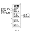
本明細書で提示する実施形態は、ガスタービンの圧縮機の健全性を監視するための方法及びシステムを開示する。図1は、圧縮機健全性監視システムの実施形態が動作可能である環境のブロック図である。環境は、ガスタービン102と、ガスタービンセンサシステム104と、圧縮機健全性監視システム106とを含む。
The embodiments presented herein disclose methods and systems for monitoring the health of a gas turbine compressor. FIG. 1 is a block diagram of an environment in which an embodiment of a compressor health monitoring system can operate. The environment includes a
ガスタービン102は、圧縮機セクションと、燃焼室と、1つ又は複数の入口抽気弁と、ロータとを一般的に含む。ガスタービン102は、圧縮機入口を通して周囲空気を取り入れる。圧縮機セクションは、多段圧縮機を含むことができる。多段圧縮機の各段は、ロータブレードの列と、それに続くステータブレードの列とを含む。作動流体が、可変入口案内翼(IGV)を通って、圧縮機の第1の段の中に流れ込む。IGVの角度が、ロータの回転速度によって作動流体の流れを制御して、ガスタービンのオフデザイン性能を向上させる。各段では、ロータブレードが作動流体を加速させる。作動流体は次いで、作動流体の運動エネルギーが静圧に変換されるステータブレード通路において減速する。必要な全体の圧力比は、必要な圧縮機段の数を追加することによって、こうして得られる。加圧された空気が次いで、燃焼室に移される。燃焼室で、圧縮された空気は好適な燃料と混合されて、点火される。燃料が燃焼すると、高圧排気となって、これがタービンロータを駆動する。タービンロータは、それに結合した機械的負荷を駆動することができる。代替的には、高圧排気ガスが吐き出されて、スラストを生成してもよい。抽気弁は、作動すると、圧縮機吐出空気の一部を、直接ガスタービン排気の中に吸い上げる。抽気弁は、ガスタービン102が起動時などの加速状態にある間、及びガスタービン102がシャットダウン時などの減速状態にある間にのみ、作動する。抽気弁は、失速状態又はサージ状態から圧縮機を保護する。抽気弁は、空気圧によって作動しても、電気機械的に作動してもよい。
The
ガスタービンセンサシステム104は、ガスタービン102のさまざまな運転パラメータを監視するためのセンサを含むことができる。ガスタービンセンサシステムは、限定はしないが、たとえば、タービン負荷、圧縮機入口温度、入口抽気熱状態、圧縮機圧力比(CPR)などの運転パラメータを監視するためのセンサを有することができる。圧縮機入口温度は、圧縮機入口の1つ又は複数の周囲位置で検知されてもよい。ガスタービンセンサシステム104は、限定はしないが、たとえば、タービン効率、タービン入口流れ、タービン出力、排気温度などの、ガスタービン102の性能パラメータを監視するためのセンサをさらに含むことができる。ガスタービンセンサシステム104は、圧縮機吐出温度(CTD)を監視するためのセンサをさらに含むことができる。CTDは、圧縮機の出口の1つ又は複数の周囲位置で監視されてもよい。ガスタービンセンサシステム104はまた、ガスタービンの運転に関連付けられた1つ又は複数の振動パラメータを測定するためのセンサを含むことができる。振動パラメータは、振動の振幅、振動の周波数を含むことができる。振動パラメータは、圧縮機のさまざまな位置で監視されてもよい。
The gas
ガスタービンセンサシステム104は、監視したパラメータを、圧縮機段の健全性状態を検出するための圧縮機健全性監視システム106に転送する。
The gas
図2は、一実施形態に従った、圧縮機健全性監視システム106のブロック図である。圧縮機監視システム106は、複数のタービンデータポイントを受信することができる。タービンデータポイントは、タービンの1つ又は複数の運転パラメータ、圧縮機の出口のさまざまな周囲位置で測定された1つ又は複数のCTD、1つ又は複数の性能パラメータなどを含むことができる。
FIG. 2 is a block diagram of the compressor
圧縮機健全性監視システム106は、ガスタービンセンサシステム104から複数のタービンデータポイントを受信するための受信モジュール202を含むことができる。ガスタービンは、有線又は無線様式で、複数のタービンデータポイントを送り出すことができる。
The compressor
圧縮機健全性監視システム106は、データビニングモジュール204をさらに含むことができる。データビニングモジュール204は、運転パラメータに基づいて、複数のタービンデータポイントを複数のバンドにカテゴリ化する。複数のタービンデータポイントは、ある時間にわたって得られることがある。この時間の間に、タービンの運転条件が変化していることがある。したがって、得られた複数のタービンデータポイントを複数のバンドにカテゴリ化することが有益であることがあり、ここで、複数のバンドのそれぞれは、特定の運転条件に対応していてよい。したがって、バンド内のCTD及び性能パラメータの変動は、ガスタービン102の運転条件から独立している。
The compressor
たとえば、複数のタービンデータポイントは、ガスタービン102の抽気熱状態に基づいて、2つのバンドにカテゴリ化されてもよい。第1のバンドが、抽気熱がオフにされたときに得られたタービンデータポイントを含んでもよく、第2のバンドが、抽気熱がオンにされたときに得られたタービンデータポイントを含んでもよい。上の2つのバンドは、圧縮機入口の2つ以上の周囲位置で測定された圧縮機入口温度(CTIF)の違いの差に基づいて、さらに2つのバンドに分割されてもよい。たとえば、CTIFの差が閾値よりも高くてもよいときに得られたタービンデータポイントが、1つのバンドにカテゴリ化されてもよく、CTIFの差が閾値よりも低いときに得られたタービンデータポイントが、もう1つのバンドにカテゴリ化されてもよい。同様のカテゴリ化が、圧縮機圧力比(CPR)に基づいて行われてもよい。
For example, the plurality of turbine data points may be categorized into two bands based on the bleed heat status of the
ビニングモジュール204は、運転パラメータの組合せに基づいて、タービンデータポイントをバンドにカテゴリ化することができる。たとえば、バンドは、抽気熱がオンにされたとき、CTIFの差がCTIF閾値よりも高いとき、及びCPRがCPR閾値よりも高いときに得られたタービンデータポイントのみからなってもよい。CPRについての閾値は13であってもよい。そのようにタービンデータポイントをバンドに分類するのは、例示の目的のためであり、タービンデータポイントは、他の運転パラメータ、又は運転パラメータの他の組合せに基づいてもまたカテゴリ化されてもよい。さらに、運転パラメータについての閾値はまた、動的に決定されてもよい。
The
圧縮機健全性監視システム106はさらに、ばらつきモジュール206から構成されてもよい。ばらつきモジュール206は、複数のバンドのそれぞれについて、CTD及び1つ又は複数の性能パラメータのうちの少なくとも1つの統計的ばらつき測定を計算する。
The compressor
ばらつきモジュール206は、ベースラインのばらつきモジュールを含むことができる。ベースラインのばらつきモジュールは、CTD及び1つ又は複数の性能パラメータの、ベースラインのばらつき測定を計算することができる。ベースラインのばらつき測定を、第1の時間ウィンドウにわたり、複数のバンドのそれぞれについて計算することができる。さまざまな実施形態において、第1の時間ウィンドウは、3〜12時間の範囲であってもよく、たとえば、6時間であってもよい。
The
ベースラインのばらつき測定は、圧縮機出口のさまざまな周囲位置で得られたCTDの差の平均値を含むことができる。ベースラインの統計的ばらつき測定は、1つ又は複数の性能パラメータの平均値を含むことができる。代替的には、ベースラインの統計的ばらつき測定は、CTDの差の中央値又は標準偏差を含むことができる。ベースラインのばらつき測定は、第1の時間ウィンドウにわたって得られた性能パラメータの中央値又は標準偏差をさらに含むことができる。 Baseline variability measurements can include an average of the CTD differences obtained at various ambient locations at the compressor outlet. The baseline statistical variability measurement may include an average value of one or more performance parameters. Alternatively, the baseline statistical variability measurement can include the median or standard deviation of the CTD differences. The baseline variability measurement may further include a median or standard deviation of performance parameters obtained over the first time window.
ばらつきモジュール206は、CTDの差及び1つ又は複数の性能パラメータの現在のばらつき測定を計算するための、現在のばらつきモジュールをさらに含むことができる。現在のばらつき測定は、その中にタービンデータポイントがカテゴリ化されていてよいすべての複数のバンドについて、計算されてもよい。さらに、現在の統計的ばらつき測定を、第2の時間ウィンドウ内で得られたタービンデータポイントについて得ることができる。第2の時間ウィンドウは、第1の時間ウィンドウよりも短くてもよい。ある実施形態においては、第2の時間ウィンドウは、15分又は30分の長さであってもよい。
The
現在のばらつき測定は、第2の時間ウィンドウにわたって得られたタービンデータポイントのCTDの差の平均値であってもよい。現在のばらつき測定は、1つ又は複数の性能パラメータの平均値をさらに含むことができる。ある実施形態においては、現在のばらつき測定は、第2の時間ウィンドウにわたって得られたタービンデータポイントの、CTDの差及び1つ又は複数の性能パラメータの中央値又は標準偏差であってもよい。 The current variability measurement may be an average value of the difference in CTD of the turbine data points obtained over the second time window. Current variability measurements can further include an average value of one or more performance parameters. In some embodiments, the current variability measurement may be the median or standard deviation of the CTD difference and one or more performance parameters of the turbine data points obtained over the second time window.
ベースラインのばらつき測定及び現在のばらつき測定は、アラームインジケータを得るために利用されてもよい。アラームモジュール208が、アラームインジケータを生成することができる。アラームインジケータは、ベースラインのばらつき測定と現在のばらつき測定との差であってもよい。たとえば、第1の時間ウィンドウにわたって得られた平均CTDの差と、第2の時間ウィンドウにわたって得られた平均CTDの差との違いを計算することによって、アラームインジケータを得ることができる。同様に、第1の時間ウィンドウにわたって得られた性能パラメータの平均値と、第2の時間ウィンドウにわたって得られた性能パラメータの平均値との差を計算することによって、アラームインジケータを得ることができる。一実施形態においては、第1の時間ウィンドウ及び第2の時間ウィンドウにわたって得られたCTDの差の中央値又は標準偏差の差を計算することによって、アラームインジケータを得ることができる。別の実施形態においては、第1の時間ウィンドウ及び第2の時間ウィンドウのそれぞれにわたって得られた性能パラメータの中央値又は標準偏差の差を計算することによって、アラームインジケータをさらに得ることができる。
Baseline variability measurements and current variability measurements may be utilized to obtain an alarm indicator. The
アラームモジュール208は、アラームインジケータを閾値と比較することができ、アラームインジケータが特定の時間よりも長い時間にわたって閾値を超えた場合に、アラームが発動してもよい。ある実施形態においては、アラームインジケータが15分よりも長い間、閾値を超えた場合に、アラームが発動する。さまざまな実施形態において、アラームインジケータが10〜60分までの範囲の時間にわたって閾値を超えた場合に、アラームが発動してもよい。
The
圧縮機健全性監視システム106は、運転パラメータ、CTD、及び性能パラメータを、ISO標準パラメータに正規化するためのISO正規化モジュールをさらに含むことができる。パラメータをISO標準パラメータに変換することによって、あらゆる環境で運転する、あらゆるガスタービンユニットに対する圧縮機健全性監視システム106の適用性を保証する。運転パラメータ、CTD、及び性能パラメータのユニット及びプロパティは、測定デバイスに依存してもよい。たとえは、CTDは、華氏及び摂氏の両方において測定されてもよい。正規化されたCTD及び正規化された性能パラメータは、ベースラインの統計的ばらつき測定及び現在のベースラインの統計的ばらつき測定を得るために、及び引き続きアラームインジケータを得るために、使用されてもよい。パラメータの正規化により、パラメータが測定されるユニットにかかわらず、システムを適用可能にすることができる。
The compressor
圧縮機健全性監視システム106は、CTDと1つ又は複数のパラメータとを組み合わせるためのセンサ融合モジュールをさらに含むことができる。Kalmanフィルタアルゴリズム、Bayesianネットワークアルゴリズム、Dempster−Shaferアルゴリズムなどの本技術分野で知られている融合アルゴリズムが、運転パラメータ、CTD、及び性能パラメータを融合するために適用されてもよい。パラメータの融合により、運転パラメータ、CTD、及び性能パラメータのそれぞれのプロパティからなる融合されたパラメータを生成することができる。一実施形態においては、第1の時間ウィンドウ及び第2の時間ウィンドウの両方について、融合されたパラメータを得ることができる。さらに、融合されたパラメータに基づいて、ベースラインのばらつき測定及び現在のばらつき測定を計算することができる。また、融合されたパラメータに対応した、ベースラインの統計的ばらつき測定と現在の統計的ばらつき測定との差に基づいて、アラームインジケータを得ることができる。
The compressor
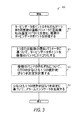
図3は、一実施形態に従った、CTDに基づく圧縮機予知診断のプロセス300を示す流れ図である。ステップ302で、複数のタービンデータポイントを得ることができる。図2に関連して言及したように、複数のタービンデータポイントは、1つ又は複数の運転パラメータを含むことができ、運転パラメータは、タービン負荷と、圧縮機入口温度と、入口抽気状態と、CPRとを含むことができる。複数のタービンデータポイントはまた、圧縮機出口の1つ又は複数の周囲位置で測定されたCTDを含むことができる。複数のタービンデータポイントは、1つ又は複数の性能パラメータをさらに含むことができ、性能パラメータは、タービン効率と、タービン入口流れと、タービン出力と、排気温度とを含むことができる。
FIG. 3 is a flow diagram illustrating a
プロセス300のステップ304で、タービンデータポイントは、1つ又は複数の運転パラメータに基づいて、複数のバンドにカテゴリ化される。たとえば、複数のタービンデータポイントは、ガスタービン102の抽気熱状態に基づいて、2つのバンドにカテゴリ化されてもよい。第1のバンドが、抽気熱がオフにされたときに得られたタービンデータポイントを含んでもよく、第2のバンドが、抽気熱がオンにされたときに得られたタービンデータポイントを含んでもよい。上の2つのバンドは、圧縮機入口の2つの周囲位置で測定されたCTIFの差に基づいて、さらに2つのバンドに分割されてもよい。たとえば、CTIFの差が閾値よりも高くてもよいときに得られたタービンデータポイントが、1つのバンドにカテゴリ化されてもよく、CTIFの差が閾値よりも低いときに得られたタービンデータポイントが、別のバンドにカテゴリ化されてもよい。同様のカテゴリ化が、圧縮機圧力比(CPR)に基づいて行われてもよい。
At
タービンデータポイントのバンドへのカテゴリ化は、2つ以上の運転パラメータに同時に基づいていてもよいことが、当業者であれば理解できるであろう。たとえば、バンドは、抽気熱がオンにされたとき、CTIFの差が閾値よりも高かったとき、及びCPRが別の閾値よりも高くてもよいときに得られたタービンデータポイントのみからなってもよい。ある実施形態においては、CPRについての閾値は13であってもよい。上記で言及したバンドの分類は例示の目的のためであり、タービンデータポイントは、他の運転パラメータ、又は運転パラメータの他の組合せに基づいてカテゴリ化されてもよいことが、当業者であれば理解できるであろう。また、それぞれの運転パラメータについての閾値は、やはり動的に決定されてもよいことが理解できるであろう。 One skilled in the art will appreciate that categorization of turbine data points into bands may be based on two or more operating parameters simultaneously. For example, a band may consist only of turbine data points obtained when bleed heat is turned on, when the CTIF difference is higher than a threshold, and when the CPR may be higher than another threshold. Good. In some embodiments, the threshold for CPR may be 13. Those skilled in the art will appreciate that the band classifications mentioned above are for illustrative purposes, and that the turbine data points may be categorized based on other operating parameters or other combinations of operating parameters. You can understand. It will also be appreciated that the threshold for each operating parameter may still be determined dynamically.
プロセス300のステップ306で、CTDの差についての統計的ばらつき測定を計算することができる。統計的ばらつき測定は、その中にタービンデータポイントがカテゴリ化されている複数のバンドのそれぞれについて計算されてもよい。ステップ306で、CTDの差についてのベースラインのばらつき測定及び現在のばらつき測定の両方を計算することができる。図2に関連して示したように、ベースラインのばらつき測定は、第1のウィンドウ期間にわたって得られたCTDの差の平均値、中央値、又は標準偏差であってもよい。同様に、現在のばらつき測定は、第2の時間ウィンドウにわたって得られたCTDの差の平均値、中央値、又は標準偏差であってもよい。
At
ステップ308で、ベースラインの統計的ばらつき測定及び現在の統計的ばらつき測定に基づいて、アラームインジケータが生成される。ある実施形態においては、アラームインジケータは、ベースラインのばらつき測定と現在のばらつき測定との差であってもよい。アラームインジケータが特定の時間よりも長い時間にわたって閾値よりも高い場合に、アラームが発動してもよい。ある実施形態においては、アラームインジケータが15分よりも長い間、閾値を超えた場合に、アラームが発動する。さまざまな実施形態において、アラームインジケータが10〜60分までの範囲の時間にわたって閾値を超えた場合に、アラームが発動してもよい。
At
プロセス300は、第1の時間ウィンドウ及び第2の時間ウィンドウにわたる、CTDの差の測定値に基づいて、アラームインジケータを評価する。アラームインジケータはまた、ガスタービン102の性能パラメータに基づいて得られてもよいことが、当業者であれば理解できるであろう。ガスタービン102の性能パラメータに基づく圧縮機予知診断のプロセスが、図4に関連して示される。
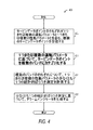
図4は、ガスタービン102の性能パラメータに基づく圧縮機予知診断のプロセス400を示す流れ図である。ステップ402で、複数のタービンデータポイントを得ることができる。複数のタービンデータポイントを得ることは、プロセス300のステップ302に関連して説明したように行われてもよい。
FIG. 4 is a flow diagram illustrating a compressor
プロセス400のステップ404で、タービンデータポイントは、1つ又は複数の運転パラメータに基づいて、複数のバンドにカテゴリ化される。複数のタービンデータポイントを複数のバンドに編成することは、プロセス300のステップ304に関連して説明したように行われてもよい。
At
プロセス400のステップ406で、ガスタービン102の1つ又は複数の性能パラメータについての統計的ばらつき測定を計算することができる。統計的ばらつき測定は、その中にタービンデータポイントがカテゴリ化されている複数のバンドのそれぞれについて計算されてもよい。ステップ406で、1つ又は複数の性能パラメータについてのベースラインのばらつき測定及び統計的ばらつき測定の両方を計算することができる。図2に関連して示したように、ベースラインの統計的ばらつき測定は、第1のウィンドウ期間にわたって得られた1つ又は複数の性能パラメータの平均値、中央値、又は標準偏差であってもよい。同様に、現在の統計的ばらつき測定は、第2の時間ウィンドウにわたって得られた1つ又は複数の性能パラメータの平均値、中央値、又は標準偏差であってもよい。
At
ステップ408で、ベースラインの統計的ばらつき測定及び現在の統計的ばらつき測定に基づいて、アラームインジケータを計算することができる。アラームインジケータを計算することは、プロセス300のステップ308に関連して説明したように実行されてもよい。
At
プロセス300及び400はさらに、運転パラメータ、CTD、及び性能パラメータを、ISO標準パラメータに正規化することができる。ある実施形態においては、ベースラインのばらつき測定及び現在のばらつき測定の両方を、正規化されたパラメータに基づいて計算することができる。さらに、アラームインジケータもまた、正規化されたパラメータに基づいて計算することができる。そのようにして得られたアラームインジケータに基づいて、アラームが発動してもよい。
図5は、一実施形態に従った、融合方法論を使用する圧縮機診断のプロセス500を示す流れ図である。プロセスは、ガスタービンセンサシステム104から、運転パラメータ、CTD、及び性能パラメータを得る。プロセスは、ガスタービン102の振動パラメータをさらに得ることができる。振動パラメータは、振動の振幅、振動の周波数などを含むことができる。
FIG. 5 is a flow diagram illustrating a process 500 for compressor diagnostics using a fusion methodology, according to one embodiment. The process obtains operating parameters, CTD, and performance parameters from the gas
CTD特徴502、性能特徴504、及び振動特徴506が、それぞれ、ガスタービンセンサシステムについてのCTD、1つ又は複数の性能パラメータ、及び振動パラメータを得ることができる。CTD、性能パラメータ、振動パラメータは次いで、組合せモジュール508に伝達される。組合せモジュール508は、CTD、性能パラメータ、及び振動パラメータのうちの少なくとも2つを融合して、融合パラメータを得ることができる。組合せモジュール508は、たとえば、Kalmanフィルタアルゴリズム、Bayesianネットワークアルゴリズム、Dempster−Shaferアルゴリズムなどの、さまざまな融合アルゴリズムを使用することができる。ある実施形態においては、CTDと運転パラメータとが融合されて、融合パラメータを得る。代替的な実施形態においては、CTDと、運転パラメータと、性能パラメータとが融合されて、融合パラメータを得ることができる。
A
融合されたパラメータは、圧縮機健全性監視モジュール106に伝達されてもよい。圧縮機健全性監視モジュールは、融合されたパラメータに基づいて、アラームインジケータを計算することができる。融合されたパラメータは、ベースラインのばらつき測定及び現在のばらつき測定を計算するために、第1の時間ウィンドウ及び第2の時間ウィンドウにわたって得られる。ベースラインのばらつき測定及び現在のばらつき測定に基づいて、アラームインジケータを計算することができる。
The merged parameters may be communicated to the compressor
本明細書で提示する実施形態は、図3、図4、及び図5で説明したステップを実行するためのコンピュータプログラム製品をさらに含む。コンピュータプログラム製品は、一時的でないコンピュータ可読媒体に記憶された符号化された命令を含む。コンピュータ可読媒体は、ランダムアクセスメモリ(RAM)、読取り専用メモリ(ROM)、プログラマブル読取り専用メモリ(PROM)、消去可能プログラマブル読取り専用メモリ(EPROM)などのうちのいずれか1つであってもよい。符号化された命令は、1つ又は複数のプロセッサによって実行されてもよい。コンピュータプログラム製品の符号化された命令は、複数のタービンデータポイントを受信するための命令と、1つ又は複数の運転パラメータに基づいて、タービンデータポイントを複数のバンドにカテゴリ化するための命令と、CTD及びガスタービン102の性能パラメータのベースラインのばらつき測定及び現在のばらつき測定を計算するための命令とを含むことができる。コンピュータプログラム製品はまた、ベースラインのばらつき測定及び現在のばらつき測定に基づいて、アラームインジケータを計算するための命令を含むことができる。コンピュータプログラム製品は、1つ又は複数の運転パラメータ、CTD、1つ又は複数の性能パラメータを、ISO標準レーティングに正規化するための命令を有することができる。
The embodiments presented herein further include a computer program product for performing the steps described in FIG. 3, FIG. 4, and FIG. The computer program product includes encoded instructions stored on a non-transitory computer readable medium. The computer readable medium may be any one of random access memory (RAM), read only memory (ROM), programmable read only memory (PROM), erasable programmable read only memory (EPROM), and the like. The encoded instructions may be executed by one or more processors. The encoded instructions of the computer program product include instructions for receiving a plurality of turbine data points and instructions for categorizing the turbine data points into a plurality of bands based on one or more operating parameters. , CTD and
コンピュータプログラム製品は、タービン102の1つ又は複数の振動パラメータを受信するための命令をさらに含むことができる。コンピュータプログラム製品は、1つ又は複数のセンサ融合技法を使用して、CTDと1つ又は複数の性能パラメータとを組み合わせるための命令をさらに含むことができる。ある実施形態においては、コンピュータプログラム製品は、1つ又は複数の融合技法を使用して、1つ又は複数の振動パラメータと、CTDと、1つ又は複数の性能パラメータとを組み合わせるための命令を含むことができる。センサ融合技法は、Kalmanフィルタアルゴリズム、Bayesianネットワークアルゴリズム、Dempster−Shaferアルゴリズムなどのうちの1つ又は複数を含むことができる。
The computer program product may further include instructions for receiving one or more vibration parameters of the
本明細書で説明した実施形態は、ひとえに例示の目的のためである。当業者は、この説明から、本明細書で提示した教示が、説明した実施形態に限定されず、添付の特許請求項の趣旨及び範囲によってのみ限定される修正形態及び変更形態により実践されてもよいことを認識するであろう。 The embodiments described herein are for illustrative purposes only. Those skilled in the art can now appreciate from this description that the teachings presented herein may be practiced with modifications and alterations that are not limited to the described embodiments, but are limited only by the spirit and scope of the appended claims. You will recognize the good.
102 ガスタービン
104 ガスタービンセンサシステム
106 圧縮機健全性監視システム
202 受信モジュール
204 データビニングモジュール
206 ばらつきモジュール
208 アラームモジュール
210 出力デバイス
502 CTD特徴ブロック
504 性能特徴ブロック
506 振動特徴ブロック
508 組合せモジュール
102
Claims (10)
前記1つ又は複数の運転パラメータに基づいて、前記タービンデータポイントを複数のバンドにカテゴリ化するステップ(304、404)と、
前記複数のバンドのそれぞれについて、前記CTD及び前記1つ又は複数の性能パラメータのうちの少なくとも1つの、少なくとも1つの統計的ばらつき測定を計算するステップ(306、406)と、
前記少なくとも1つの統計的ばらつき測定に基づいて、アラームインジケータを生成するステップ(308、408)と
を含む、圧縮機の健全性を監視するための方法(300、400)。 Receiving a plurality of said turbine data points, each of the turbine data points including one or more operating parameters and at least one of a compressor discharge temperature (CTD) and one or more performance parameters ( 302, 402),
Categorizing the turbine data points into a plurality of bands based on the one or more operating parameters (304, 404);
Calculating (306, 406) at least one statistical variability measurement of at least one of the CTD and the one or more performance parameters for each of the plurality of bands;
Generating an alarm indicator based on the at least one statistical variability measurement (308, 408) and a method (300, 400) for monitoring compressor health.
第1の時間ウィンドウにわたり、前記複数のバンドのそれぞれについて、前記CTD及び前記1つ又は複数の性能パラメータのうちの少なくとも1つのベースラインのばらつき測定を計算するステップと、
前記第1の時間ウィンドウよりも短い第2の時間ウィンドウにわたり、前記複数のバンドのそれぞれについて、前記CTD及び前記1つ又は複数の性能パラメータのうちの少なくとも1つの現在のばらつき測定を計算するステップと
を含む、請求項1記載の方法。 Calculating (306, 406) the at least one statistical variability measure;
Calculating a baseline variability measurement of at least one of the CTD and the one or more performance parameters for each of the plurality of bands over a first time window;
Calculating a current variability measurement of at least one of the CTD and the one or more performance parameters for each of the plurality of bands over a second time window shorter than the first time window; The method of claim 1 comprising:
前記ベースラインのばらつき測定と、前記現在のばらつき測定とを比較するステップと、
前記現在のばらつき測定が前記ベースラインのばらつき測定からあらかじめ定義された差だけ外れた場合に、前記アラームインジケータを生成するステップと
を含む、請求項4記載の方法。 Generating the alarm indicator (308, 408),
Comparing the baseline variability measurement with the current variability measurement;
Generating the alarm indicator when the current variation measurement deviates from the baseline variation measurement by a predefined difference.
前記1つ又は複数の運転パラメータに基づいて、前記タービンデータポイントを複数のバンドにカテゴリ化するためのデータビニングモジュール(204)と、
前記複数のバンドのそれぞれについて、前記CTD及び前記1つ又は複数の性能パラメータのうちの少なくとも1つの、少なくとも1つの統計的ばらつき測定を計算するためのばらつきモジュール(206)と、
前記少なくとも1つの統計的ばらつき測定に基づいて、アラームインジケータを生成するためのアラームモジュール(208)と
を含む、圧縮機の健全性を監視するためのシステム(106)。 For receiving a plurality of said turbine data points, each of the turbine data points including one or more operating parameters and at least one of a compressor discharge temperature (CTD) and one or more performance parameters A receiving module (202);
A data binning module (204) for categorizing the turbine data points into a plurality of bands based on the one or more operating parameters;
A variation module (206) for calculating at least one statistical variation measurement of at least one of the CTD and the one or more performance parameters for each of the plurality of bands;
A system (106) for monitoring compressor health comprising an alarm module (208) for generating an alarm indicator based on the at least one statistical variability measurement.
第1の時間ウィンドウにわたり、前記複数のバンドのそれぞれについて、前記CTD及び前記1つ又は複数の性能パラメータのうちの少なくとも1つのベースラインのばらつき測定を計算するためのベースラインのばらつきモジュールと、
前記第1の時間ウィンドウよりも短い第2の時間ウィンドウにわたり、前記複数のバンドのそれぞれについて、前記CTD及び前記1つ又は複数の性能パラメータのうちの少なくとも1つの現在のばらつき測定を計算するための現在のばらつきモジュールと
を含む、請求項6記載のシステム。 The variation module (206)
A baseline variability module for calculating a variability measurement of at least one of the CTD and the one or more performance parameters for each of the plurality of bands over a first time window;
For calculating a current variation measurement of at least one of the CTD and the one or more performance parameters for each of the plurality of bands over a second time window that is shorter than the first time window; The system of claim 6 including a current variation module.
タービンデータポイントのそれぞれが1つ又は複数の運転パラメータと、圧縮機吐出温度(CTD)及び1つ又は複数の性能パラメータのうちの少なくとも1つとを含む、複数の前記タービンデータポイントを受信する(302、402)ようにさせ、
前記1つ又は複数の運転パラメータに基づいて、前記タービンデータポイントを複数のバンドにカテゴリ化する(304、404)ようにさせ、
前記複数のバンドのそれぞれについて、前記CTD及び前記1つ又は複数の性能パラメータのうちの少なくとも1つの、少なくとも1つの統計的ばらつき測定を計算する(306、406)ようにさせ、
前記少なくとも1つの統計的ばらつき測定に基づいて、アラームインジケータを生成する(308、408)ようにさせる、
コンピュータプログラム製品。 A computer program product comprising a non-transitory computer readable medium encoded with computer executable instructions for monitoring the health of a compressor, wherein the computer executable instructions are one when executed Or to multiple processors
A plurality of turbine data points are received (302), each turbine data point including one or more operating parameters and at least one of a compressor discharge temperature (CTD) and one or more performance parameters. 402)
Categorizing (304, 404) the turbine data points into a plurality of bands based on the one or more operating parameters;
Calculating (306, 406) at least one statistical variability measurement for at least one of the CTD and the one or more performance parameters for each of the plurality of bands;
Causing an alarm indicator to be generated (308, 408) based on the at least one statistical variation measurement;
Computer program product.
第1の時間ウィンドウにわたり、前記複数のバンドのそれぞれについて、前記CTD及び前記1つ又は複数の性能パラメータのうちの少なくとも1つのベースラインのばらつき測定を計算するようにさせ、
前記第1の時間ウィンドウよりも短い第2の時間ウィンドウにわたり、前記複数のバンドのそれぞれについて、前記CTD及び前記1つ又は複数の性能パラメータのうちの少なくとも1つの現在のばらつき測定を計算するようにさせる、
コンピュータ実行可能命令をさらに含む請求項8記載のコンピュータプログラム製品。 The one or more processors;
Over a first time window, for each of the plurality of bands, to calculate a baseline variability measurement of at least one of the CTD and the one or more performance parameters;
Calculating a current variation measurement of at least one of the CTD and the one or more performance parameters for each of the plurality of bands over a second time window shorter than the first time window; Let
The computer program product of claim 8, further comprising computer executable instructions.
前記ベースラインのばらつき測定と、前記現在のばらつき測定とを比較するようにさせ、
前記現在のばらつき測定が前記ベースラインのばらつき測定からあらかじめ定義された差だけ外れた場合に、前記アラームインジケータを生成するようにさせる、
コンピュータ実行可能命令をさらに含む請求項9記載のコンピュータプログラム製品。 The one or more processors;
To compare the baseline variation measurement with the current variation measurement;
Causing the alarm indicator to be generated when the current variation measurement deviates by a predefined difference from the baseline variation measurement;
The computer program product of claim 9, further comprising computer executable instructions.
Applications Claiming Priority (2)
| Application Number | Priority Date | Filing Date | Title |
|---|---|---|---|
| US12/976,255 US8471702B2 (en) | 2010-12-22 | 2010-12-22 | Method and system for compressor health monitoring |
| US12/976,255 | 2010-12-22 |
Publications (3)
| Publication Number | Publication Date |
|---|---|
| JP2012132450A true JP2012132450A (en) | 2012-07-12 |
| JP2012132450A5 JP2012132450A5 (en) | 2015-02-05 |
| JP6081057B2 JP6081057B2 (en) | 2017-02-15 |
Family
ID=46210527
Family Applications (1)
| Application Number | Title | Priority Date | Filing Date |
|---|---|---|---|
| JP2011278135A Expired - Fee Related JP6081057B2 (en) | 2010-12-22 | 2011-12-20 | Method and system for monitoring compressor health |
Country Status (5)
| Country | Link |
|---|---|
| US (1) | US8471702B2 (en) |
| JP (1) | JP6081057B2 (en) |
| CN (1) | CN102539162B (en) |
| DE (1) | DE102011056644B4 (en) |
| FR (1) | FR2969704A1 (en) |
Cited By (2)
| Publication number | Priority date | Publication date | Assignee | Title |
|---|---|---|---|---|
| JP2015038348A (en) * | 2013-07-24 | 2015-02-26 | エア チャイナ リミテッド | Monitoring method and device with respect to failure of turbine blade fracture and rotating shaft blocking in apu |
| JP2016061293A (en) * | 2014-09-17 | 2016-04-25 | ゼネラル・エレクトリック・カンパニイ | Automated prognostics systems and methods |
Families Citing this family (15)
| Publication number | Priority date | Publication date | Assignee | Title |
|---|---|---|---|---|
| US9501920B2 (en) * | 2012-06-22 | 2016-11-22 | K.L. Harring Transportation LLC | Cargo tracking and monitoring system |
| KR101606239B1 (en) * | 2013-05-31 | 2016-03-24 | 삼성에스디에스 주식회사 | System and method for analyzing sensing data |
| CN104340372A (en) * | 2013-07-31 | 2015-02-11 | 上海杰之能信息科技有限公司 | Performance monitoring method and device and monitoring server of airborne auxiliary power unit (APU) |
| US20150047368A1 (en) * | 2013-08-13 | 2015-02-19 | General Electric Company | Systems and methods for controlling gas turbines |
| GB201315654D0 (en) * | 2013-09-03 | 2013-10-16 | Rolls Royce Plc | Operating parameter monitoring method |
| FR3013834B1 (en) * | 2013-11-28 | 2015-12-25 | Airbus Operations Sas | METHOD FOR MERGING SENSOR DATA USING A COHERENCE CRITERION |
| US9790834B2 (en) * | 2014-03-20 | 2017-10-17 | General Electric Company | Method of monitoring for combustion anomalies in a gas turbomachine and a gas turbomachine including a combustion anomaly detection system |
| FI128394B (en) * | 2014-12-09 | 2020-04-30 | Hydroline Oy | Monitoring device and method for determining operating health of pressure medium operated device |
| EP3258333A1 (en) * | 2016-06-17 | 2017-12-20 | Siemens Aktiengesellschaft | Method and system for monitoring sensor data of rotating equipment |
| CN106525442B (en) * | 2016-09-18 | 2019-01-18 | 中国石油天然气股份有限公司 | A kind of method and device monitoring gas turbine gas circuit performance |
| US20180162537A1 (en) * | 2016-12-09 | 2018-06-14 | United Technologies Corporation | Environmental control system air circuit |
| CN107340137B (en) * | 2017-07-25 | 2023-10-10 | 杭州华电半山发电有限公司 | Turbine efficiency on-line monitoring system device and method for heavy gas turbine |
| US10822993B2 (en) * | 2018-06-06 | 2020-11-03 | General Electric Company | Method for operating a turbo machine |
| CN110209552B (en) * | 2019-05-29 | 2023-09-22 | 北京百度网讯科技有限公司 | Equipment management method and device |
| EP3862549A1 (en) * | 2020-02-05 | 2021-08-11 | General Electric Company | Method for operating a power plant, and power plant |
Citations (8)
| Publication number | Priority date | Publication date | Assignee | Title |
|---|---|---|---|---|
| JP2002371989A (en) * | 2001-04-17 | 2002-12-26 | General Electric Co <Ge> | Monitoring and controlling method, and monitoring device for compressor |
| JP2004124946A (en) * | 2002-10-04 | 2004-04-22 | General Electric Co <Ge> | Method and system for detecting stall of compressor or sign of surge |
| JP2006063986A (en) * | 2004-08-26 | 2006-03-09 | United Technol Corp <Utc> | Apparatus and method for assessing health of device |
| JP2008082339A (en) * | 2006-09-27 | 2008-04-10 | General Electric Co <Ge> | Aerodynamic stability managing system and its controller |
| JP2009075081A (en) * | 2007-07-27 | 2009-04-09 | General Electric Co <Ge> | Fleet anomaly detection method |
| JP2010025106A (en) * | 2008-07-18 | 2010-02-04 | General Electric Co <Ge> | Stall and surge detection system and method |
| US7765873B2 (en) * | 2007-07-20 | 2010-08-03 | Rosemount Inc. | Pressure diagnostic for rotary equipment |
| JP2010261459A (en) * | 2009-05-07 | 2010-11-18 | General Electric Co <Ge> | Failure detection and protection of multi-stage compressor |
Family Cites Families (16)
| Publication number | Priority date | Publication date | Assignee | Title |
|---|---|---|---|---|
| GB8902645D0 (en) * | 1989-02-07 | 1989-03-30 | Smiths Industries Plc | Monitoring |
| US5447059A (en) * | 1993-12-27 | 1995-09-05 | Solar Turbines Incorporated | Apparatus and method for determining gas turbine engine life |
| US5546015A (en) | 1994-10-20 | 1996-08-13 | Okabe; Toyohiko | Determining device and a method for determining a failure in a motor compressor system |
| US5857321A (en) * | 1996-06-11 | 1999-01-12 | General Electric Company | Controller with neural network for estimating gas turbine internal cycle parameters |
| US6138081A (en) * | 1998-04-09 | 2000-10-24 | Cmr Technologies, Inc. | Data acquisition system and method for monitoring gas turbine engine testing |
| US6799951B2 (en) | 2002-07-25 | 2004-10-05 | Carrier Corporation | Compressor degradation detection system |
| US6719526B2 (en) * | 2002-08-23 | 2004-04-13 | General Electric Company | Method for categorizing the operating mode of a gas turbine |
| US7247348B2 (en) | 2004-02-25 | 2007-07-24 | Honeywell International, Inc. | Method for manufacturing a erosion preventative diamond-like coating for a turbine engine compressor blade |
| US20070283695A1 (en) | 2006-06-13 | 2007-12-13 | Honeywell International, Inc. | System and method for turbocharger early failure detection and avoidance |
| US8014880B2 (en) * | 2006-09-29 | 2011-09-06 | Fisher-Rosemount Systems, Inc. | On-line multivariate analysis in a distributed process control system |
| US20080126012A1 (en) * | 2006-11-29 | 2008-05-29 | United Technologies Corpoation | State initialization for gas turbine engine performance diagnostics |
| US7493809B1 (en) * | 2007-10-04 | 2009-02-24 | General Electric Company | Method and system for measuring deformation in turbine blades |
| CN101545828A (en) * | 2008-03-10 | 2009-09-30 | 通用电气公司 | Independent sensing system for a winding turbine |
| US8131509B2 (en) | 2008-03-23 | 2012-03-06 | United Technologies Corporation | Method of system design for failure detectability |
| DE102008021102A1 (en) | 2008-04-28 | 2009-10-29 | Siemens Aktiengesellschaft | Efficiency monitoring of a compressor |
| CN101532910B (en) * | 2009-04-16 | 2011-05-25 | 北京理工大学 | Acceleration performance evaluation test method and test apparatus of turbo-charger |
-
2010
- 2010-12-22 US US12/976,255 patent/US8471702B2/en active Active
-
2011
- 2011-12-19 DE DE102011056644.9A patent/DE102011056644B4/en active Active
- 2011-12-20 JP JP2011278135A patent/JP6081057B2/en not_active Expired - Fee Related
- 2011-12-21 FR FR1162224A patent/FR2969704A1/en not_active Withdrawn
- 2011-12-22 CN CN201110463149.XA patent/CN102539162B/en not_active Expired - Fee Related
Patent Citations (8)
| Publication number | Priority date | Publication date | Assignee | Title |
|---|---|---|---|---|
| JP2002371989A (en) * | 2001-04-17 | 2002-12-26 | General Electric Co <Ge> | Monitoring and controlling method, and monitoring device for compressor |
| JP2004124946A (en) * | 2002-10-04 | 2004-04-22 | General Electric Co <Ge> | Method and system for detecting stall of compressor or sign of surge |
| JP2006063986A (en) * | 2004-08-26 | 2006-03-09 | United Technol Corp <Utc> | Apparatus and method for assessing health of device |
| JP2008082339A (en) * | 2006-09-27 | 2008-04-10 | General Electric Co <Ge> | Aerodynamic stability managing system and its controller |
| US7765873B2 (en) * | 2007-07-20 | 2010-08-03 | Rosemount Inc. | Pressure diagnostic for rotary equipment |
| JP2009075081A (en) * | 2007-07-27 | 2009-04-09 | General Electric Co <Ge> | Fleet anomaly detection method |
| JP2010025106A (en) * | 2008-07-18 | 2010-02-04 | General Electric Co <Ge> | Stall and surge detection system and method |
| JP2010261459A (en) * | 2009-05-07 | 2010-11-18 | General Electric Co <Ge> | Failure detection and protection of multi-stage compressor |
Cited By (2)
| Publication number | Priority date | Publication date | Assignee | Title |
|---|---|---|---|---|
| JP2015038348A (en) * | 2013-07-24 | 2015-02-26 | エア チャイナ リミテッド | Monitoring method and device with respect to failure of turbine blade fracture and rotating shaft blocking in apu |
| JP2016061293A (en) * | 2014-09-17 | 2016-04-25 | ゼネラル・エレクトリック・カンパニイ | Automated prognostics systems and methods |
Also Published As
| Publication number | Publication date |
|---|---|
| CN102539162A (en) | 2012-07-04 |
| CN102539162B (en) | 2016-09-14 |
| JP6081057B2 (en) | 2017-02-15 |
| US8471702B2 (en) | 2013-06-25 |
| DE102011056644A1 (en) | 2012-06-28 |
| FR2969704A1 (en) | 2012-06-29 |
| US20120161965A1 (en) | 2012-06-28 |
| DE102011056644B4 (en) | 2023-02-09 |
Similar Documents
| Publication | Publication Date | Title |
|---|---|---|
| JP6081057B2 (en) | Method and system for monitoring compressor health | |
| US7941281B2 (en) | System and method for rotor blade health monitoring | |
| JP5903223B2 (en) | Blade monitoring system | |
| US7062370B2 (en) | Model-based detection, diagnosis of turbine engine faults | |
| JP5260343B2 (en) | Plant operating condition monitoring method | |
| US20100114502A1 (en) | System and method for article monitoring | |
| US11591925B2 (en) | Monitoring device, method for monitoring target device, and program | |
| EP3102989B1 (en) | Estimation of health parameters in industrial gas turbines | |
| JP2011090382A (en) | Monitoring system | |
| JP6329338B2 (en) | System and method for monitoring stator vane health | |
| JP5898865B2 (en) | System and method for monitoring airfoil health | |
| JP2016070272A (en) | Systems and methods for fault analysis | |
| JP2012013079A (en) | System and method for monitoring health of airfoil | |
| JP6219945B2 (en) | Method for detecting turbomachine degradation by monitoring turbomachine performance | |
| JP2013137797A (en) | Plant operation state monitoring method | |
| JP5653786B2 (en) | Anomaly detection device | |
| US8342010B2 (en) | Surge precursor protection systems and methods | |
| Romessis et al. | Fusion of Gas Turbines Diagnostic Inference: The Dempster-Schafer Approach | |
| JP4523826B2 (en) | Gas turbine monitoring device and gas turbine monitoring system | |
| KR102224983B1 (en) | Inspecting and Diagnosing Device For Gas Turbin Combustor | |
| Du et al. | Dynamic simulations of post-stall performance in multistage axial compressors | |
| WO2006107295A1 (en) | Model-based detection, diagnosis of turbine engine faults | |
| JP2014051978A (en) | Turbomachine having flow monitoring system and method of monitoring flow in turbomachine | |
| KR20230148669A (en) | Method and system for analzing performance of gas turbine compressor based on machine learning, and apparatus for cleaning the compressor using the same | |
| JP2017082618A (en) | Operation monitoring system for axial flow turbo machine |
Legal Events
| Date | Code | Title | Description |
|---|---|---|---|
| A521 | Request for written amendment filed |
Free format text: JAPANESE INTERMEDIATE CODE: A523 Effective date: 20141211 |
|
| A621 | Written request for application examination |
Free format text: JAPANESE INTERMEDIATE CODE: A621 Effective date: 20141211 |
|
| A977 | Report on retrieval |
Free format text: JAPANESE INTERMEDIATE CODE: A971007 Effective date: 20151023 |
|
| A131 | Notification of reasons for refusal |
Free format text: JAPANESE INTERMEDIATE CODE: A131 Effective date: 20151201 |
|
| A521 | Request for written amendment filed |
Free format text: JAPANESE INTERMEDIATE CODE: A523 Effective date: 20160208 |
|
| A131 | Notification of reasons for refusal |
Free format text: JAPANESE INTERMEDIATE CODE: A131 Effective date: 20160802 |
|
| A521 | Request for written amendment filed |
Free format text: JAPANESE INTERMEDIATE CODE: A523 Effective date: 20160831 |
|
| TRDD | Decision of grant or rejection written | ||
| A01 | Written decision to grant a patent or to grant a registration (utility model) |
Free format text: JAPANESE INTERMEDIATE CODE: A01 Effective date: 20161227 |
|
| A61 | First payment of annual fees (during grant procedure) |
Free format text: JAPANESE INTERMEDIATE CODE: A61 Effective date: 20170118 |
|
| R150 | Certificate of patent or registration of utility model |
Ref document number: 6081057 Country of ref document: JP Free format text: JAPANESE INTERMEDIATE CODE: R150 |
|
| R250 | Receipt of annual fees |
Free format text: JAPANESE INTERMEDIATE CODE: R250 |
|
| R250 | Receipt of annual fees |
Free format text: JAPANESE INTERMEDIATE CODE: R250 |
|
| R250 | Receipt of annual fees |
Free format text: JAPANESE INTERMEDIATE CODE: R250 |
|
| LAPS | Cancellation because of no payment of annual fees |