JP2012132320A - Fluid transporting apparatus, ship with the same, and fluid for transporting device - Google Patents
Fluid transporting apparatus, ship with the same, and fluid for transporting device Download PDFInfo
- Publication number
- JP2012132320A JP2012132320A JP2010282755A JP2010282755A JP2012132320A JP 2012132320 A JP2012132320 A JP 2012132320A JP 2010282755 A JP2010282755 A JP 2010282755A JP 2010282755 A JP2010282755 A JP 2010282755A JP 2012132320 A JP2012132320 A JP 2012132320A
- Authority
- JP
- Japan
- Prior art keywords
- fluid
- tank
- tanks
- chamber
- transfer device
- Prior art date
- Legal status (The legal status is an assumption and is not a legal conclusion. Google has not performed a legal analysis and makes no representation as to the accuracy of the status listed.)
- Granted
Links
- 239000012530 fluid Substances 0.000 title claims abstract description 296
- 230000005484 gravity Effects 0.000 claims abstract description 86
- 239000000843 powder Substances 0.000 claims abstract description 55
- 238000005192 partition Methods 0.000 claims abstract description 39
- 238000003756 stirring Methods 0.000 claims description 44
- 229910052751 metal Inorganic materials 0.000 claims description 35
- 239000002184 metal Substances 0.000 claims description 35
- 239000007787 solid Substances 0.000 claims description 23
- 239000002245 particle Substances 0.000 claims description 11
- 239000004519 grease Substances 0.000 claims description 10
- 229910052721 tungsten Inorganic materials 0.000 claims description 8
- 239000010937 tungsten Substances 0.000 claims description 8
- WHXSMMKQMYFTQS-UHFFFAOYSA-N Lithium Chemical group [Li] WHXSMMKQMYFTQS-UHFFFAOYSA-N 0.000 claims description 7
- 229910052744 lithium Inorganic materials 0.000 claims description 7
- WFKWXMTUELFFGS-UHFFFAOYSA-N tungsten Chemical group [W] WFKWXMTUELFFGS-UHFFFAOYSA-N 0.000 claims description 7
- 230000033001 locomotion Effects 0.000 description 9
- 239000013535 sea water Substances 0.000 description 6
- 230000007423 decrease Effects 0.000 description 5
- 239000007788 liquid Substances 0.000 description 5
- 238000004062 sedimentation Methods 0.000 description 5
- 230000001174 ascending effect Effects 0.000 description 4
- 230000000694 effects Effects 0.000 description 4
- QSHDDOUJBYECFT-UHFFFAOYSA-N mercury Chemical compound [Hg] QSHDDOUJBYECFT-UHFFFAOYSA-N 0.000 description 4
- 229910052753 mercury Inorganic materials 0.000 description 4
- 229920003051 synthetic elastomer Polymers 0.000 description 4
- 239000005061 synthetic rubber Substances 0.000 description 4
- 230000006835 compression Effects 0.000 description 3
- 238000007906 compression Methods 0.000 description 3
- XLYOFNOQVPJJNP-UHFFFAOYSA-N water Substances O XLYOFNOQVPJJNP-UHFFFAOYSA-N 0.000 description 3
- 239000006185 dispersion Substances 0.000 description 2
- 230000009189 diving Effects 0.000 description 2
- 238000005339 levitation Methods 0.000 description 2
- 230000001141 propulsive effect Effects 0.000 description 2
- 229910001111 Fine metal Inorganic materials 0.000 description 1
- 230000033228 biological regulation Effects 0.000 description 1
- 238000007599 discharging Methods 0.000 description 1
- 238000006073 displacement reaction Methods 0.000 description 1
- 239000000463 material Substances 0.000 description 1
- 239000000203 mixture Substances 0.000 description 1
- 230000002093 peripheral effect Effects 0.000 description 1
- 150000003657 tungsten Chemical class 0.000 description 1
Images

Classifications
-
- F—MECHANICAL ENGINEERING; LIGHTING; HEATING; WEAPONS; BLASTING
- F04—POSITIVE - DISPLACEMENT MACHINES FOR LIQUIDS; PUMPS FOR LIQUIDS OR ELASTIC FLUIDS
- F04B—POSITIVE-DISPLACEMENT MACHINES FOR LIQUIDS; PUMPS
- F04B43/00—Machines, pumps, or pumping installations having flexible working members
- F04B43/02—Machines, pumps, or pumping installations having flexible working members having plate-like flexible members, e.g. diaphragms
- F04B43/06—Pumps having fluid drive
- F04B43/067—Pumps having fluid drive the fluid being actuated directly by a piston
-
- B—PERFORMING OPERATIONS; TRANSPORTING
- B63—SHIPS OR OTHER WATERBORNE VESSELS; RELATED EQUIPMENT
- B63B—SHIPS OR OTHER WATERBORNE VESSELS; EQUIPMENT FOR SHIPPING
- B63B39/00—Equipment to decrease pitch, roll, or like unwanted vessel movements; Apparatus for indicating vessel attitude
- B63B39/02—Equipment to decrease pitch, roll, or like unwanted vessel movements; Apparatus for indicating vessel attitude to decrease vessel movements by displacement of masses
- B63B39/03—Equipment to decrease pitch, roll, or like unwanted vessel movements; Apparatus for indicating vessel attitude to decrease vessel movements by displacement of masses by transferring liquids
-
- B—PERFORMING OPERATIONS; TRANSPORTING
- B63—SHIPS OR OTHER WATERBORNE VESSELS; RELATED EQUIPMENT
- B63B—SHIPS OR OTHER WATERBORNE VESSELS; EQUIPMENT FOR SHIPPING
- B63B43/00—Improving safety of vessels, e.g. damage control, not otherwise provided for
- B63B43/02—Improving safety of vessels, e.g. damage control, not otherwise provided for reducing risk of capsizing or sinking
- B63B43/04—Improving safety of vessels, e.g. damage control, not otherwise provided for reducing risk of capsizing or sinking by improving stability
- B63B43/06—Improving safety of vessels, e.g. damage control, not otherwise provided for reducing risk of capsizing or sinking by improving stability using ballast tanks
-
- F—MECHANICAL ENGINEERING; LIGHTING; HEATING; WEAPONS; BLASTING
- F04—POSITIVE - DISPLACEMENT MACHINES FOR LIQUIDS; PUMPS FOR LIQUIDS OR ELASTIC FLUIDS
- F04B—POSITIVE-DISPLACEMENT MACHINES FOR LIQUIDS; PUMPS
- F04B15/00—Pumps adapted to handle specific fluids, e.g. by selection of specific materials for pumps or pump parts
- F04B15/02—Pumps adapted to handle specific fluids, e.g. by selection of specific materials for pumps or pump parts the fluids being viscous or non-homogeneous
-
- F—MECHANICAL ENGINEERING; LIGHTING; HEATING; WEAPONS; BLASTING
- F04—POSITIVE - DISPLACEMENT MACHINES FOR LIQUIDS; PUMPS FOR LIQUIDS OR ELASTIC FLUIDS
- F04B—POSITIVE-DISPLACEMENT MACHINES FOR LIQUIDS; PUMPS
- F04B43/00—Machines, pumps, or pumping installations having flexible working members
- F04B43/02—Machines, pumps, or pumping installations having flexible working members having plate-like flexible members, e.g. diaphragms
- F04B43/025—Machines, pumps, or pumping installations having flexible working members having plate-like flexible members, e.g. diaphragms two or more plate-like pumping members in parallel
- F04B43/026—Machines, pumps, or pumping installations having flexible working members having plate-like flexible members, e.g. diaphragms two or more plate-like pumping members in parallel each plate-like pumping flexible member working in its own pumping chamber
-
- F—MECHANICAL ENGINEERING; LIGHTING; HEATING; WEAPONS; BLASTING
- F04—POSITIVE - DISPLACEMENT MACHINES FOR LIQUIDS; PUMPS FOR LIQUIDS OR ELASTIC FLUIDS
- F04B—POSITIVE-DISPLACEMENT MACHINES FOR LIQUIDS; PUMPS
- F04B43/00—Machines, pumps, or pumping installations having flexible working members
- F04B43/02—Machines, pumps, or pumping installations having flexible working members having plate-like flexible members, e.g. diaphragms
- F04B43/06—Pumps having fluid drive
- F04B43/073—Pumps having fluid drive the actuating fluid being controlled by at least one valve
- F04B43/0736—Pumps having fluid drive the actuating fluid being controlled by at least one valve with two or more pumping chambers in parallel
-
- F—MECHANICAL ENGINEERING; LIGHTING; HEATING; WEAPONS; BLASTING
- F04—POSITIVE - DISPLACEMENT MACHINES FOR LIQUIDS; PUMPS FOR LIQUIDS OR ELASTIC FLUIDS
- F04B—POSITIVE-DISPLACEMENT MACHINES FOR LIQUIDS; PUMPS
- F04B43/00—Machines, pumps, or pumping installations having flexible working members
- F04B43/12—Machines, pumps, or pumping installations having flexible working members having peristaltic action
- F04B43/1253—Machines, pumps, or pumping installations having flexible working members having peristaltic action by using two or more rollers as squeezing elements, the rollers moving on an arc of a circle during squeezing
- F04B43/1261—Machines, pumps, or pumping installations having flexible working members having peristaltic action by using two or more rollers as squeezing elements, the rollers moving on an arc of a circle during squeezing the rollers being placed at the outside of the tubular flexible member
-
- F—MECHANICAL ENGINEERING; LIGHTING; HEATING; WEAPONS; BLASTING
- F04—POSITIVE - DISPLACEMENT MACHINES FOR LIQUIDS; PUMPS FOR LIQUIDS OR ELASTIC FLUIDS
- F04B—POSITIVE-DISPLACEMENT MACHINES FOR LIQUIDS; PUMPS
- F04B9/00—Piston machines or pumps characterised by the driving or driven means to or from their working members
- F04B9/08—Piston machines or pumps characterised by the driving or driven means to or from their working members the means being fluid
- F04B9/10—Piston machines or pumps characterised by the driving or driven means to or from their working members the means being fluid the fluid being liquid
- F04B9/109—Piston machines or pumps characterised by the driving or driven means to or from their working members the means being fluid the fluid being liquid having plural pumping chambers
- F04B9/117—Piston machines or pumps characterised by the driving or driven means to or from their working members the means being fluid the fluid being liquid having plural pumping chambers the pumping members not being mechanically connected to each other
-
- Y—GENERAL TAGGING OF NEW TECHNOLOGICAL DEVELOPMENTS; GENERAL TAGGING OF CROSS-SECTIONAL TECHNOLOGIES SPANNING OVER SEVERAL SECTIONS OF THE IPC; TECHNICAL SUBJECTS COVERED BY FORMER USPC CROSS-REFERENCE ART COLLECTIONS [XRACs] AND DIGESTS
- Y10—TECHNICAL SUBJECTS COVERED BY FORMER USPC
- Y10T—TECHNICAL SUBJECTS COVERED BY FORMER US CLASSIFICATION
- Y10T137/00—Fluid handling
- Y10T137/8593—Systems
- Y10T137/86187—Plural tanks or compartments connected for serial flow
Abstract
Description
本発明は、例えば高比重の微粉体を含む高比重の流動体を移送するためのものであって、特に、潜水艇等を含む船、車両、構造物等の重心位置の移動を行うことができる流動体移送装置、それを備える船、及び移送装置用流動体に関する。 The present invention is for transferring a fluid having a high specific gravity including, for example, fine powder having a high specific gravity, and is particularly capable of moving the position of the center of gravity of a ship, vehicle, structure or the like including a submersible craft. The present invention relates to a fluid transfer device that can be used, a ship including the same, and a fluid for a transfer device.
従来の流動体移送装置の一例として、図2に示すものがある(例えば、特許文献1参照。)。この流動体移送装置1は、同図に示すように、微粉体を含む流動体2を貯留する2つの第1及び第2タンク3、4と、これらの第1タンク3と第2タンク4とを互いに連通し、かつ、一部が柔軟性を有する柔軟管部5aを有する配管5と、正逆両方向に回動移動可能であって、回動しながら柔軟管部5aを押圧して、柔軟管部5a内の流動体2を順逆両方向に移動させるローラ部6、6とを備えている。
An example of a conventional fluid transfer device is shown in FIG. 2 (see, for example, Patent Document 1). As shown in the figure, the fluid transfer device 1 includes two first and second tanks 3 and 4 for storing a
そして、図2に示すように、ローラ部6は、回転アーム7の両方の各端部に設けられている。また、柔軟管部5aは、ハウジング8に形成された凹部8aの断面U字形状の内面に沿って配置されている。
As shown in FIG. 2, the roller unit 6 is provided at each end of both of the rotating arms 7. The flexible tube portion 5 a is disposed along the inner surface of the concave portion 8 a formed in the
この流動体移送装置1によると、回転アーム7を所望の方向に回動させることによって、ローラ部6が回動しながら柔軟管部5aを押圧して、柔軟管部5a内の流動体2を所望の順逆両方向に移動させることができる。これによって、2つの第1及び第2タンク3、4のうちの所望のタンクに貯留されている流動体2を、他方のタンクへ移送することができる。
According to this fluid transfer device 1, by rotating the rotary arm 7 in a desired direction, the roller portion 6 presses the flexible tube portion 5a while rotating, and the
つまり、図2に示す従来の流動体移送装置1によると、ローラ部6が回動しながら柔軟管部5aを押圧して、柔軟管部5a内の流動体2を所望の方向に移動させていくと共に、柔軟管部5aに対するローラ部6による押圧力が解除されたときに、押圧されて扁平な形状の柔軟管部5aが、その弾性力によって元の例えば円形断面に復元することができる。そして、この復元するときに、後続の流動体2がこの円形に復元した柔軟管部5a内に移動してくるメカニズムとなっている。
That is, according to the conventional fluid transfer device 1 shown in FIG. 2, the flexible tube portion 5a is pressed while the roller portion 6 is rotated, and the
しかし、図2に示す従来の流動体移送装置1では、ローラ部6の柔軟管部5aに対する押圧力が解除されたときに、押圧されて扁平形状となっている柔軟管部5aが、その弾性力によって元の断面円形に復元するのに或る程度の時間が掛かるので、この流動体2が押し出された柔軟管部5a内に後続の流動体2が移動してくるまでの移動時間は、柔軟管部5aの復元速度に依存していると言える。
However, in the conventional fluid transfer device 1 shown in FIG. 2, when the pressing force of the roller portion 6 against the flexible tube portion 5a is released, the flexible tube portion 5a that is pressed and has a flat shape has its elasticity. Since it takes a certain amount of time to restore the original circular shape by the force, the movement time until the
従って、一方のタンク3又は4内の流動体2を他方のタンク4又は3に移送する移送流量を大きくするためにローラ部6の回動移動速度を大きくしても、必要な移送流量を得ることができないことがある。
Therefore, even if the rotational movement speed of the roller portion 6 is increased in order to increase the transfer flow rate for transferring the
そして、柔軟管部5aの復元力には、バラツキがあるので、流動体2の移送流量にバラツキが生じ、そのために、高精度の流量精度を得ることができない。
And since there is variation in the restoring force of the flexible tube part 5a, variation occurs in the transfer flow rate of the
また、柔軟管部5aの復元力の低下によって移送流量が低下するので、耐久性に優れた流動体移送装置の開発が望まれている。 In addition, since the transfer flow rate is reduced due to a reduction in the restoring force of the flexible tube portion 5a, development of a fluid transfer device having excellent durability is desired.
本発明は、上記のような課題を解決するためになされたものであり、2つのタンクのうちの所望のタンクに貯留されている比重及び粘性の大きい流動体を、他方のタンクへ迅速で正確な流量精度で移送することができ、しかも耐久性に優れた流動体移送装置、それを備える船、及び移送装置用流動体を提供することを目的としている。 The present invention has been made to solve the above-described problems, and a fluid having a large specific gravity and viscosity stored in a desired tank of two tanks can be quickly and accurately transferred to the other tank. An object of the present invention is to provide a fluid transfer device that can be transferred with a high flow rate accuracy and has excellent durability, a ship equipped with the fluid transfer device, and a fluid for the transfer device.
本発明に係る流動体移送装置は、微粉体を含む流動体を貯留する2つのタンクと、これら2つのタンクを互いに連通する連通管と、2つの前記タンクのうちの一方の前記タンクに貯留されている前記流動体を他方の前記タンクに移送することができると共に、他方の前記タンクに貯留されている前記流動体を一方の前記タンクに移送することができる移送部とを備える流動体移送装置において、2つのそれぞれの前記タンクは、変形自在な隔壁によって仕切られた第1室と第2室とを有し、それぞれの前記第1室には、非圧縮性流体が貯留され、かつ、それぞれの前記第2室には、前記非圧縮性流体よりも比重及び粘度が大きい前記流動体が貯留され、これら2つの前記第2室が前記連通管で互いに連通し、前記移送部は、2つの前記第1室のうちの所望の一方の前記第1室に前記非圧縮性流体を供給したときに、他方の前記第1室から前記非圧縮性流体を排出することができる構成であることを特徴とするものである。 The fluid transfer device according to the present invention is stored in two tanks that store a fluid containing fine powder, a communication pipe that connects the two tanks to each other, and one of the two tanks. A fluid transfer device comprising: a transfer unit capable of transferring the fluid that is stored in the other tank to the other tank, and the transfer unit that is capable of transferring the fluid stored in the other tank to the one tank Each of the two tanks has a first chamber and a second chamber partitioned by a deformable partition wall, in which the incompressible fluid is stored in each of the first chambers, and The fluid having a specific gravity and viscosity larger than those of the incompressible fluid is stored in the second chamber, and the two second chambers communicate with each other through the communication pipe. The first chamber When the incompressible fluid is supplied to one of the desired first chambers, the incompressible fluid can be discharged from the other first chamber. is there.
本発明に係る流動体移送装置によると、移送部によって、一方のタンクの第1室に非圧縮性流体を供給していくと、この第1室内の非圧縮性流体の体積が増加するにつれて、隔壁が第1室側から第2室側に変形して、この一方のタンクの第2室の体積が減少していく。これによって、この第2室に貯留されている流動体を、連結管に通して他方のタンクの第2室に移送することができる。このとき、この他方のタンクの第2室内の流動体の体積が増加するにつれて、このタンクの隔壁が第2室側から第1室側に変形して、この他方のタンクの第1室の体積が減少していく。これによって、第1室に貯留されている非圧縮性流体が、この第1室から排出される。 According to the fluid transfer device according to the present invention, when the incompressible fluid is supplied to the first chamber of one tank by the transfer unit, the volume of the incompressible fluid in the first chamber increases. The partition wall is deformed from the first chamber side to the second chamber side, and the volume of the second chamber of this one tank decreases. Thereby, the fluid stored in the second chamber can be transferred to the second chamber of the other tank through the connecting pipe. At this time, as the volume of the fluid in the second chamber of the other tank increases, the partition wall of the tank is deformed from the second chamber side to the first chamber side, and the volume of the first chamber of the other tank is increased. Will decrease. As a result, the incompressible fluid stored in the first chamber is discharged from the first chamber.
このようにして、非圧縮性流体よりも比重が大きい流動体を、所望の一方のタンクの第2室から他方のタンクの第2室に移送することによって、これら2つのタンクの重心位置を一方のタンク側から他方のタンク側に移動させることができる。 In this way, the fluid having a specific gravity greater than that of the incompressible fluid is transferred from the desired second chamber of one tank to the second chamber of the other tank, so that the center of gravity positions of these two tanks are adjusted to one side. It can be moved from one tank side to the other tank side.
そして、非圧縮性流体は、流動体よりも比重及び粘度が小さいものであるので、移送部は、非圧縮性流体を各々のタンクの第1室に対して効率よく供給及び排出することができる。よって、2つのタンクのうちの所望のタンクの第2室に貯留されている比重及び粘度の大きい流動体を他方のタンクの第2室に効率よく移送することができる。 Since the incompressible fluid has a specific gravity and viscosity smaller than the fluid, the transfer unit can efficiently supply and discharge the incompressible fluid to the first chamber of each tank. . Therefore, the fluid having a large specific gravity and viscosity stored in the second chamber of the desired tank of the two tanks can be efficiently transferred to the second chamber of the other tank.
また、第1室と第2室とは、変形自在な隔壁によって仕切られているので、タンク内の流動体と非圧縮性流体とが互いに混ざり合うことがなく、2つのタンクの重心位置を所望のタンク側に正確に移動させることができる。 Further, since the first chamber and the second chamber are partitioned by a deformable partition wall, the fluid in the tank and the incompressible fluid are not mixed with each other, and the center of gravity positions of the two tanks are desired. It can be moved accurately to the tank side.
更に、流動体は、非圧縮性流体よりも粘度が大きいものとしているので、流動体に含まれている比重の大きい微粉体が、この流動体中において沈降することを抑制することができ、この流動体における比重のバラツキを小さくすることができる。よって、移動させる流動体の重量精度の向上、及びこの2つのタンクの重心位置の移動精度の向上を図ることができる。 Furthermore, since the fluid has a higher viscosity than the incompressible fluid, the fine powder having a large specific gravity contained in the fluid can be prevented from settling in the fluid. Variations in specific gravity in the fluid can be reduced. Therefore, the weight accuracy of the fluid to be moved can be improved, and the movement accuracy of the center of gravity of the two tanks can be improved.
この発明に係る流動体移送装置において、前記連通管には、当該連通管内の流動体を撹拌することができる撹拌装置が設けられているものとすることができる。 In the fluid transfer device according to the present invention, the communication pipe may be provided with a stirring device capable of stirring the fluid in the communication pipe.
このようにすると、連通管内を通って移送される流動体を撹拌することができるので、2つの各タンク内に貯留されている流動体の略全体を満遍なく撹拌することが可能である。これによって、流動体に含まれる比重の大きい微粉体を迅速に、しかも適切に分散させて沈降を防止することができる。そして、微粉体を適切に分散させることによって、流動体における比重及び粘度のバラツキを小さくすることができる。粘度のバラツキを小さくすることによって、流動体の移送を安定してスムースに行うことができる。 In this way, since the fluid transferred through the communication pipe can be stirred, it is possible to uniformly stir almost the entire fluid stored in the two tanks. As a result, fine powder having a large specific gravity contained in the fluid can be quickly and appropriately dispersed to prevent sedimentation. And dispersion | distribution of the specific gravity and viscosity in a fluid can be made small by disperse | distributing fine powder appropriately. By reducing the variation in viscosity, the fluid can be stably and smoothly transferred.
この発明に係る流動体移送装置において、前記撹拌装置は、一軸偏心ねじポンプとすることができる。 In the fluid transfer device according to the present invention, the stirring device may be a uniaxial eccentric screw pump.
このようにすると、連通管内を通る流動体を撹拌することができると共に、一軸偏心ねじポンプの吐出圧力に基づいて移送力を発生することができる。これによって、移送部が、各々のタンクの第1室に対して非圧縮性流体を供給したり排出するために必要とするエネルギの低減を図ることができる。 In this way, the fluid passing through the communication pipe can be agitated, and a transfer force can be generated based on the discharge pressure of the uniaxial eccentric screw pump. As a result, the energy required for the transfer unit to supply and discharge the incompressible fluid to and from the first chamber of each tank can be reduced.
この発明に係る流動体移送装置において、前記撹拌装置又は前記連通管には、圧力調整装置が設けられ、前記圧力調整装置は、前記撹拌装置又は前記連通管の内側と外側とを連通するシリンダ部と、このシリンダ部内に配置されたピストン部と、前記ピストン部を前記撹拌装置又は前記連通管内の圧力を高める側に付勢する付勢手段とを有するものとすることができる。 In the fluid transfer device according to the present invention, a pressure adjusting device is provided in the stirring device or the communication pipe, and the pressure adjusting device is a cylinder portion that communicates the inside and the outside of the stirring device or the communication tube. And a piston part disposed in the cylinder part, and an urging means for urging the piston part toward the pressure increasing side in the stirring device or the communication pipe.
このようにすると、撹拌装置又は連通管の外面に例えば外圧P1が掛かっているときに、ピストン部には、外圧P1と付勢手段の付勢力に基づく圧力P2との合計圧力P3(=P1+P2)が掛かる。そして、ピストン部に掛かる圧力P3は、撹拌装置又は連通管内の流動体に伝わり、その結果、撹拌装置又は連通管内の流動体の圧力がP3となる。この流動体の圧力P3と外圧P1との差圧はP2(=P1+P2−P1)であり、この差圧P2(設定圧力)は、付勢手段の付勢力に基づくものであり、外圧P1を含んでいないので、外圧P1が変化しても一定のこの差圧P2によって、外側の例えば海水等の液体や気体が、撹拌装置又は連通管内に浸入することを防止でき、ひいてはタンク内に浸入することを防止できる。よって、流動体を確実に移送することができ、2つのタンクの重心位置を迅速で正確に移動させることができる。 In this way, when, for example, the external pressure P1 is applied to the outer surface of the stirring device or the communication pipe, the piston portion has a total pressure P3 (= P1 + P2) of the external pressure P1 and the pressure P2 based on the urging force of the urging means. It takes. And the pressure P3 applied to a piston part is transmitted to the fluid in a stirring apparatus or a communicating pipe, As a result, the pressure of the fluid in a stirring apparatus or a communicating pipe becomes P3. The differential pressure between the fluid pressure P3 and the external pressure P1 is P2 (= P1 + P2-P1), and this differential pressure P2 (set pressure) is based on the urging force of the urging means and includes the external pressure P1. Therefore, even if the external pressure P1 changes, the constant pressure difference P2 can prevent the outside liquid or gas such as seawater from entering the stirrer or the communication pipe, and thus enter the tank. Can be prevented. Therefore, the fluid can be reliably transferred, and the gravity center positions of the two tanks can be moved quickly and accurately.
同様に、例えば周囲の温度変化によって撹拌装置、連通管、及びタンクが収縮したり膨張する場合でも、この圧力調整装置によって撹拌装置又は連通管内の圧力P3を外圧P1よりも所定の設定圧力P2だけ高くなるように調整できる。これによって、上記と同様の効果を奏することができる。 Similarly, even when, for example, the stirring device, the communication pipe, and the tank contract or expand due to a change in ambient temperature, the pressure adjusting device causes the pressure P3 in the stirring device or the communication pipe to be a predetermined set pressure P2 rather than the external pressure P1. It can be adjusted to be higher. As a result, the same effects as described above can be obtained.
この発明に係る流動体移送装置において、前記流動体は、半固体状体又はペースト状体と金属製微粉体とが調合されたものであって、比重が5〜9であり、前記半固体状体又はペースト状体と前記金属製微粉体との重量比が15:85〜5:95であるものとすることができる。 In the fluid transfer device according to the present invention, the fluid is prepared by mixing a semi-solid body or paste-like body and a metal fine powder, and has a specific gravity of 5 to 9, and the semi-solid state. The weight ratio of the body or paste-like body to the metal fine powder may be 15:85 to 5:95.
このように、粘度が大きい半固体状体又はペースト状体に金属製微粉体を調合して流動体を作ることによって、金属製微粉体がこの半固体状体又はペースト状体中において沈降することを十分に抑制することができ、この流動体における比重や粘度のバラツキを小さくすることができる。 In this way, by preparing a fluid by mixing metal fine powder with a semi-solid body or paste-like body having a high viscosity, the metal fine powder settles in the semi-solid body or paste-like body. Can be sufficiently suppressed, and variations in specific gravity and viscosity in the fluid can be reduced.
そして、金属製微粉体を採用することによって、比重が5〜9の流動体を作ることができる。このように、流動体の比重を5以上とすることによって、例えばこの流動体移送装置を全長の小さい潜水艇に適用した場合は、この艇の前後傾斜や左右傾斜の姿勢制御を可能にすることができる。 And the fluid of specific gravity 5-9 can be made by employ | adopting metal fine powder. Thus, by setting the specific gravity of the fluid to 5 or more, for example, when this fluid transfer device is applied to a submersible craft having a small overall length, it is possible to control the posture of the boat to tilt forward and backward or to the left and right. Can do.
また、半固体状体又はペースト状体と金属製微粉体との重量比を15:85〜5:95とすると、半固体状体又はペースト状体中における金属製微粉体の沈降を抑制することができ、その結果、前記のように、艇の姿勢制御を可能にすると共に、流動体を、2つのタンク間を移動させることができる流動性を確保することができる。 Further, when the weight ratio of the semi-solid body or paste body to the metal fine powder is 15:85 to 5:95, the sedimentation of the metal fine powder in the semi-solid body or paste body is suppressed. As a result, as described above, the posture of the boat can be controlled, and fluidity that can move the fluid between the two tanks can be ensured.
この発明に係る流動体移送装置において、前記金属製微粉体は、粒径が10〜150μmのタングステン金属であり、前記半固体状体又はペースト状体は、リチウムグリースであるものとすることができる。 In the fluid transfer device according to the present invention, the metal fine powder may be tungsten metal having a particle size of 10 to 150 μm, and the semi-solid body or paste body may be lithium grease. .
このように、粒径が10〜150μmの金属製微粉体を採用すると、比重の大きい流動体を作ることができる。 Thus, when a metal fine powder having a particle size of 10 to 150 μm is employed, a fluid having a large specific gravity can be produced.
つまり、粒径が10μm未満であると、微粉体どうしが凝集し易くなり、この凝集した微粉体どうしの間に隙間が形成されるので、流動体の比重を大きくすることができない。粒径が150μmを超えると、微粉体どうしの隙間が大きくなり、流動体の比重を大きくすることができない。 That is, when the particle size is less than 10 μm, the fine powders easily aggregate and a gap is formed between the aggregated fine powders, so that the specific gravity of the fluid cannot be increased. When the particle diameter exceeds 150 μm, the gap between the fine powders becomes large, and the specific gravity of the fluid cannot be increased.
そして、金属製微粉体としてタングステン金属を使用し、半固体状体又はペースト状体としてリチウムグリースを使用することによって、高比重であって、常温及び大気圧環境下で安定しており、人体及び自然界への影響が殆ど無く、低廉な流動体を提供することができる。 And, by using tungsten metal as a metal fine powder and using lithium grease as a semi-solid or paste-like body, it has a high specific gravity and is stable under normal temperature and atmospheric pressure environment. There is almost no influence on the natural world, and an inexpensive fluid can be provided.
本発明に係る流動体移送装置を備える船は、本発明に係る流動体移送装置を備えることを特徴とするものである。 The ship provided with the fluid transfer device according to the present invention includes the fluid transfer device according to the present invention.
本発明に係る流動体移送装置を備える船によると、この船が備える流動体移送装置は、本発明に係る流動体移送装置において説明したように作用する。 According to the ship provided with the fluid transfer device according to the present invention, the fluid transfer device provided in the ship operates as described in the fluid transfer device according to the present invention.
本発明に係る移送装置用流動体は、微粉体を含む流動体を貯留する2つのタンクと、これら2つのタンクを互いに連通する連通管と、2つの前記タンクのうちの一方の前記タンクに貯留されている前記流動体を他方の前記タンクに移送することができると共に、他方の前記タンクに貯留されている前記流動体を一方の前記タンクに移送することができる移送部とを備える流動体移送装置に使用される流動体において、半固体状体又はペースト状体と金属製微粉体とが調合されたものであって、比重が5〜9であり、前記半固体状体又はペースト状体と前記金属製微粉体との重量比が15:85〜5:95であることを特徴とするものである。 A fluid for a transfer device according to the present invention is stored in two tanks that store a fluid containing fine powder, a communication pipe that connects the two tanks to each other, and one of the two tanks. A fluid transfer unit comprising: a transfer unit capable of transferring the fluid that has been stored to the other tank, and that can transfer the fluid stored in the other tank to the one tank. In the fluid used in the apparatus, a semi-solid body or paste-like body and a metal fine powder are prepared, the specific gravity is 5 to 9, and the semi-solid body or paste-like body The weight ratio to the metal fine powder is 15:85 to 5:95.
本発明に係る移送装置用流動体によると、流動体移送装置に使用することによって、本発明に係る流動体移送装置において説明したように作用する。 According to the fluid for a transfer device according to the present invention, when used in the fluid transfer device, the fluid acts as described in the fluid transfer device according to the present invention.
この発明に係る移送装置用流動体において、前記金属製微粉体は、粒径が10〜150μmのタングステン金属製であり、前記半固体状体又はペースト状体は、リチウムグリースであるものとすることができる。 In the fluid for a transfer device according to the present invention, the metal fine powder is made of tungsten metal having a particle size of 10 to 150 μm, and the semi-solid body or paste body is lithium grease. Can do.
このようにすると、本発明に係る流動体移送装置において説明したように作用する。 If it does in this way, it will act as explained in the fluid transfer device concerning the present invention.
本発明に係る流動体移送装置によると、上記のように構成されているので、非圧縮性流体よりも比重及び粘度の大きい流動体を、2つのタンクのうちの所望の一方のタンクの第2室から、他方のタンクの第2室に迅速に、しかも正確な流量精度で移送することが可能である。 According to the fluid transfer device according to the present invention, since it is configured as described above, a fluid having a specific gravity and a viscosity larger than those of the incompressible fluid is used as the second of the desired one of the two tanks. It is possible to transfer from the chamber to the second chamber of the other tank quickly and with an accurate flow rate accuracy.
よって、例えばこの流動体移送装置を潜水艇等を含む船に使用すると、これら潜水艇等の重心位置を迅速に、しかも正確に移動させて姿勢制御することができる。そして、このように姿勢制御する場合の一例として、潜水艇では、潜航及び浮上するときに行われる前後傾斜があり、この前後傾斜を迅速で正確な傾斜角度となるように行なうことによって、推進用駆動部による少ない推進動力を使用して、潜航及び浮上を迅速に行えるようにすることができる。 Therefore, for example, when this fluid transfer device is used in a ship including a submersible craft, the position of the center of gravity of the submersible craft can be quickly and accurately moved to control the attitude. As an example of attitude control in this way, in a submersible craft, there is a forward / backward inclination performed when diving and ascending, and by performing this forward / backward inclination so as to have a rapid and accurate inclination angle, It is possible to perform submergence and levitation quickly by using less propulsive power by the drive unit.
また、姿勢制御する場合の他の一例として、潜水艇等を含む船の船内の可搬重量物(荷物等)又は乗組員等による左右傾斜がある。この船の左右傾斜を迅速で正確な傾斜角度となるように行なうことによって、船の左右バランスを迅速で安全に行えるようにすることができる。 In addition, as another example of posture control, there is a left-right inclination by a heavy load (such as luggage) or a crew member in a ship including a submersible craft. By performing the right / left inclination of the ship so as to obtain a quick and accurate inclination angle, the left / right balance of the ship can be quickly and safely performed.
更に、2つの各タンクに設けられている変形可能な隔壁は、流動体を移送するときに非圧縮性流体の圧力が掛かって変形するようになっており、隔壁の一部に硬質部材が押し付けられて変形するような構成となってはいないので、変形される隔壁の寿命を長引かせることができる。その結果、耐久性に優れた流動体移送装置を提供することができる。 Furthermore, the deformable partition walls provided in each of the two tanks are deformed by the pressure of the incompressible fluid when the fluid is transferred, and a hard member is pressed against a part of the partition walls. Therefore, the life of the deformed partition wall can be extended. As a result, a fluid transfer device with excellent durability can be provided.
そして、タンクの第1室に対して粘度の比較的小さい非圧縮性流体を供給したり排出を行なうことによって、隔壁を隔てて第2室に貯留されている粘度の比較的大きい流動体を移送する構成としたので、例えば粘度の比較的大きい流動体を、ポンプを使用して直接に移送する場合と比較して、移送のためのエネルギの低減を図ることができる。 Then, by supplying or discharging an incompressible fluid having a relatively small viscosity to the first chamber of the tank, the fluid having a relatively large viscosity stored in the second chamber is transferred across the partition wall. Since it was set as the structure which carries out, it can aim at reduction of the energy for transfer compared with the case where the fluid with comparatively large viscosity is directly transferred using a pump, for example.
また、上記のように潜水艇等の重心位置を移動させるためには、流動体として比重の大きい水銀を使用することが効果的であるが、本発明に係る比重の大きい微粉体を含む比重の大きい流動体を使用することによって、水銀を使用することなく、重心位置を迅速で確実に移動させることができる。 In order to move the position of the center of gravity of a submersible craft as described above, it is effective to use mercury having a large specific gravity as a fluid, but the specific gravity including fine powder having a large specific gravity according to the present invention is not limited. By using a large fluid, the position of the center of gravity can be moved quickly and reliably without using mercury.
そして、本発明に係る移送装置用流動体を、上記のように流動体移送装置に使用すると、上記と同様の効果を奏することができる。 And if the fluid for transfer devices concerning the present invention is used for a fluid transfer device as mentioned above, the same effect as mentioned above can be produced.
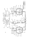
以下、本発明に係る流動体移送装置、及び移送装置用流動体の一実施形態を、図1を参照して説明する。この流動体移送装置11は、高比重の微粉体を含む高比重の流動体12を移送するためのものであって、特に、潜水艇等を含む船、車両、構造物等の重心位置の移動を行うことができるものである。この実施形態では、流動体移送装置11を例えば船の潜水艇に適用した例を挙げて説明する。
Hereinafter, an embodiment of a fluid transfer device and a fluid for a transfer device according to the present invention will be described with reference to FIG. This
図1は、流動体移送装置11を備える潜水艇のその流動体移送装置11を示す断面図である。この流動体移送装置11は、高比重の微粉体を含む高比重の流動体12を貯留する第1タンク13及び第2タンク14と、これら2つの第1及び第2タンク13、14を互いに連通する連通管15と、第1タンク13に貯留されている流動体12を第2タンク14に移送することができると共に、第2タンク14に貯留されている流動体12を第1タンク13に移送することができる移送部16とを備えている。
FIG. 1 is a cross-sectional view showing a
このように、高比重の流動体12を移送することによって、この流動体移送装置11、ひいては潜水艇の重心位置を所望の距離だけ移動させることができるようになっている。そして、これによって、潜水艇の姿勢制御を行なえるようになっている。
In this way, by transferring the fluid 12 having a high specific gravity, the center of gravity of the
なお、図1において、太線で示すラインは、高比重流動体ラインである。この高比重流動体ラインは、比重の大きい流動体12が収容されている管である。そして、細線で示すラインは、非圧縮性流体ラインである。この非圧縮性流体ラインは、比重の小さい非圧縮性流体17が収容されている管である。
In addition, in FIG. 1, the line shown with a thick line is a high specific gravity fluid line. This high specific gravity fluid line is a tube in which the fluid 12 having a large specific gravity is accommodated. And the line shown with a thin line is an incompressible fluid line. This incompressible fluid line is a tube in which an
図1に示す2つの各第1及び第2タンク13、14は、それぞれ同等のものであるので、同図の左側に示す第1タンク13を説明し、右側に示す第2タンク14の説明を省略する。
The two first and
第1タンク13は、図1に示すように、胴部の膨れた樽状のものであり、例えば合成ゴム製の変形自在な隔壁18によって密封状態で、上下に仕切られて形成された第1室19と第2室20とを有している。
As shown in FIG. 1, the
そして、上側の第1室19には、非圧縮性流体17が貯留されており、下側の第2室20には、高比重の流動体12が貯留されている。非圧縮性流体17は、例えば油又は水等の液体である。そして、流動体12は、後述するように、非圧縮性流体17よりも比重及び粘度が大きいものであり、高比重の微粉体を含む高比重の流動体12である。
An
隔壁18は、例えば変形自在な柔軟性を有する合成ゴムによって形成されている。そして、この隔壁18は、図1に示すように、第1及び第2室19、20のそれぞれに略同量の非圧縮性流体17及び流動体12が貯留されているときは、実線で示すように、略扁平な形状となって略水平に配置された状態となる。そして、第1タンク13(又は第2タンク14)の第2室20に貯留されている流動体12が、第2タンク14(又は第1タンク13)の第2室20に移送された状態では、これら第1及び第2タンク13、14に設けられているそれぞれの隔壁18は、二点鎖線で示すように、カップ状及び逆カップ状(又は略逆カップ状及び略カップ状)の形状となる。つまり、この隔壁18は、変形する前の元の形状がカップ状となるように形成されたものである。
The
従って、図1に示す隔壁18は、略扁平な形状となって略水平に配置された状態において、図には示さないが、第1及び第2タンク13、14のそれぞれの内周面に沿う円環状部分は、屈曲している。
Accordingly, the
また、図1に示すように、第1及び第2タンク13、14のそれぞれの第2室20は、連通管15で互いに連結されて連通されている。なお、連通管15の両方の各端部は、それぞれの第2室20を形成する底壁13a、14aと結合している。そして、第1及び第2タンク13、14のそれぞれの第2室20に貯留されている流動体12は、この連通管15を通って、第2及び第1タンク14、13のそれぞれの第2室20に移送される。そして、この連通管15の略中央部分には、撹拌装置21が設けられている。
Further, as shown in FIG. 1, the second chambers 20 of the first and
撹拌装置21は、連通管15内の流動体12を撹拌することができるものであり、比重の大きい流動体12に含まれている微粉体を、この流動体12中に分散させて沈降を防止することができるものである。この撹拌装置21は、例えば一軸偏心ねじポンプである。
The
この一軸偏心ねじポンプは、高粘度の流動体12(例えば微粉体を含む半固体状体又はペースト状体)を移送することができるものであり、図1に示すように、吸込み口及び吐出口として機能する第1開口部22と、吐出口及び吸込み口として機能する第2開口部23とを備えている。この第1及び第2開口部22、23は、連通管15の途中の各端部と接続している。
This uniaxial eccentric screw pump is capable of transferring a fluid 12 having a high viscosity (for example, a semi-solid body or a paste body containing fine powder). As shown in FIG. And a
なお、この一軸偏心ねじポンプは、図には示さないが、ロータとステータとを備えており、例えばロータが電気モータによって回転駆動されて、正逆いずれの方向にも回転するようになっている。ステータは固定側部に固定されており、このステータに形成されている内孔にロータが回動自在に装着されている。 Although not shown in the drawing, this uniaxial eccentric screw pump includes a rotor and a stator. For example, the rotor is driven to rotate by an electric motor so as to rotate in either the forward or reverse direction. . The stator is fixed to a fixed side portion, and a rotor is rotatably mounted in an inner hole formed in the stator.
このロータが正転(又は逆転)することによって、流動体12を第1開口部22(又は第2開口部23)から吸い込んで、第2開口部23(又は第1開口部22)から吐出することができる。そして、ロータが回転することによって、流動体12を撹拌することができ、流動体12に含まれている微粉体を、この流動体12中に分散させることができる。このように、この撹拌装置21は、流動体12を撹拌しながら移送することができるものである。
When the rotor rotates forward (or reverse), the fluid 12 is sucked from the first opening 22 (or the second opening 23) and discharged from the second opening 23 (or the first opening 22). be able to. Then, by rotating the rotor, the fluid 12 can be stirred, and the fine powder contained in the fluid 12 can be dispersed in the fluid 12. Thus, this stirring
この撹拌装置21によると、図1に示す連通管15内を通って移送される流動体12を撹拌することができるので、第1及び第2の各タンク13、14内に貯留されている比重の大きい流動体12の略全体を満遍なく撹拌することが可能である。これによって、流動体12に含まれる微粉体を迅速に、しかも適切に分散させて沈降を防止することができる。そして、微粉体を適切に分散させることによって、流動体12における比重及び粘度のバラツキを小さくすることができる。粘度のバラツキを小さくすることによって、流動体12の移送を安定してスムースに行うことができる。
According to the stirring
次に、図1に示す圧力調整装置24について説明する。この圧力調整装置24は、撹拌装置21、連通管15、第1タンク13、及び第2タンク14等を潜水艇の外側に設けた場合に、これら撹拌装置21、連通管15、第1タンク13、及び第2タンク14等のそれぞれの内圧が、外側の海水の水圧(深度圧による外圧)よりも一定の圧力(差圧)だけ高くなるように調整するためのものである。
Next, the
この圧力調整装置24は、図1に示すように、シリンダ部27を備えている。このシリンダ部27は、第1圧力調整管25及び第2圧力調整管26を介して撹拌装置21の内側と外側(例えば海水側)とを連通させている。
The
この撹拌装置21の内側とは、この撹拌装置21が備える一軸偏心ねじポンプのロータの外面とステータの内面とによって形成されている空間である。この空間は、流動体12を収容することができるものであり、ロータが回転することによって第1開口部22(又は第2開口部23)側から第2開口部23(又は第1開口部22)側に移動して、流動体12を移送するようになっている。そして、このように流動体12が移送されることによって撹拌される。
The inner side of the stirring
そして、シリンダ部27内には、前後方向に摺動自在にピストン部28が装着され、このピストン部28に対して、ピストン部28を撹拌装置21内の圧力を高める側に付勢する付勢手段29(例えば圧縮コイルばね)が設けられている。
A
また、図1に示すように、第1圧力調整管25には、フィルタ30及び元弁31が設けられ、第2圧力調整管26には、圧力変換器32が設けられている。
Further, as shown in FIG. 1, the first
この圧力変換器32は、図1に示す外ケース32a内に柔軟性を有する合成ゴム製の隔壁(図示せず)が設けられている。この隔壁は、第1圧力調整管25内に収容されている油、水等の非圧縮性流体17と、第2圧力調整管26内に収容されている流動体12とを密封状態で仕切ると共に、非圧縮性流体17側及び流動体12側の圧力を受けて、その受けた圧力を、この隔壁を介して流動体12側及び非圧縮性流体17側に伝達することができるようになっている。
The
次に、この圧力調整装置24の作用を説明する。この圧力調整装置24によると、撹拌装置21の外装部21aの外面に例えば外圧P1が掛かっているときに、ピストン部28には、外圧P1と付勢手段29(圧縮コイルばね)の付勢力に基づく圧力P2との合計圧力P3(=P1+P2)が掛かる。そして、ピストン部28に掛かる圧力P3は、撹拌装置21内の空間に収容されている流動体12に伝わり、その結果、撹拌装置21内の空間の流動体12の圧力がP3となる。この流動体12の圧力P3と外圧P1との差圧はP2(=P1+P2−P1)であり、この差圧P2(設定圧力)は、付勢手段29の付勢力に基づくものであって、外圧P1を含んでいないので、外圧P1が変化しても一定のこの差圧P2によって、外側の例えば海水等の液体や気体が、撹拌装置21内の空間に浸入することを防止できる。
Next, the operation of the
そして、この空間に収容されている流動体12は、連通管15を通って第1又は第2タンク13、14の各第2室20内に移送される。また、この空間に収容されている流動体12に掛かる合計圧力P3(=P1+P2)は、ロータとステータとの隙間を通って第1及び第2タンク13、14の両方に伝達される。これによって、撹拌装置21と同様に、外側の海水等の液体や気体が、連通管15、第1タンク13、第2タンク14、及び貯留タンク33内に浸入することを防止できる。よって、この流動体移送装置11を使用して、流動体12を確実に移送することができ、2つの第1及び第2タンク13、14の重心位置を迅速で正確に移動させることができる。
Then, the fluid 12 accommodated in this space is transferred into the second chambers 20 of the first or
同様に、例えば周囲の温度変化によって撹拌装置21、連通管15、並びに、第1及び第2タンク13、14が収縮したり膨張する場合でも、この圧力調整装置24によって撹拌装置21、連通管15、並びに、第1及び第2タンク13、14内の圧力P3を外圧P1よりも所定の設定圧力P2だけ高くなるように調整できる。これによって、上記と同様の効果を奏することができる。
Similarly, for example, even when the stirring
次に、図1を参照して移送部16を説明する。この移送部16は、第1及び第2タンク13、14の2つの第1室19のうちの所望の第1室19に非圧縮性流体17を供給したときに、他方の第1室19から非圧縮性流体17を排出することができるものであり、供給ポンプ34、方向切換弁35、及び貯留タンク33を備えている。そして、これら供給ポンプ34、方向切換弁35、及び貯留タンク33は、例えば潜水艇の外側に設けられている。
Next, the
図1に示す供給ポンプ34は、例えば容積ポンプであり、電動機で所定方向に回転駆動される。この供給ポンプ34は、その吐出口が供給管36を介して方向切換弁35のPポートと接続し、その吸込み口が供給管37を介して貯留タンク33と接続している。この貯留タンク33には、非圧縮性流体17が密封した状態で貯留されている。
The
方向切換弁35は、そのTポートが排出管38を介して貯留タンク33と接続している。そして、方向切換弁35のAポートは、給排管39を介して中空の案内部41と接続している。この案内部41は、第1タンク13の上壁13aに固定して設けられ、この案内部41の内部空間41aは、外側と密封された状態で、第1タンク13の第1室19と連通している。
The
また、方向切換弁35のBポートは、給排管40を介して中空の案内部41と接続している。この案内部41は、第2タンク14の上壁14bに固定して設けられ、この案内部41の内部空間41aは、外側と密封された状態で、第2タンク14の第1室19と連通している。そして、それぞれの給排管39、40には、フィルタ42が設けられている。
In addition, the B port of the
更に、図1に示すように、第1及び第2タンク13、14に設けられているそれぞれの案内部41の内部空間41aには、ロッド43が配置されている。各ロッド43は、案内部41の内部空間41aに沿って上下方向に移動自在に設けられ、各ロッド43の下端部には、例えば円板状の隔壁保持部44が略水平に固定して設けられている。この隔壁保持部44は、隔壁18に結合して設けられている。また、各ロッド43には、直動軸受が設けられている。
Further, as shown in FIG. 1, a
図1に示す第1及び第2タンク13、14の内部に二点鎖線で示すものは、隔壁保持部44及びロッド43が、上昇位置及び下降位置に移動している状態を示している。そして、隔壁保持部44が昇降移動すると、隔壁18が上側に移動する状態(逆カップ状となる状態)、及び隔壁18が下側に移動する状態(カップ状となる状態)となる。
What is indicated by a two-dot chain line inside the first and
この隔壁保持部44は、第1及び第2の各タンク13、14の第1室19内の非圧縮性流体17、及び第2室20内の流動体12が増減したときに、隔壁18の中央部分を略水平状態で昇降移動させるようにするものである。要は、隔壁18の中央部分が屈曲変形することによって、この隔壁18が第1及び第2の各室19、20の各給排孔46を閉じないようにするためのものである。
The
この方向切換弁35によると、図1に示すように、スプールが左側位置の状態では、PポートとAポートとが接続した状態、及びTポートとBポートとが接続した状態となり、供給ポンプ34の吐出口から吐出された非圧縮性流体17を、供給管36、給排管39、及び案内部41の内部空間41aに通して第1タンク13の第1室19に供給することができる。
According to this
そして、第2タンク14の第1室19に収容されている非圧縮性流体17が、案内部41の内部空間41aを通って給排管40、及び排出管38を通って貯留タンク33に排出されるようにすることができる。
Then, the
そして、方向切換弁35のスプールが図示しない右側位置に切り換わると、PポートとBポートとが接続した状態、及びTポートとAポートとが接続した状態となり、供給ポンプ34の吐出口から吐出された非圧縮性流体17を、供給管36、給排管40、及び案内部41の内部空間41aに通して第2タンク14の第1室19に供給することができる。
When the spool of the
そして、第1タンク13の第1室19に収容されている非圧縮性流体17が、案内部41の内部空間41aを通って給排管39、及び排出管38を通って貯留タンク33に排出されるようにすることができる。
Then, the
次に、流動体12の説明をする。流動体12は、半固体状体又はペースト状体(例えばグリース)と金属製微粉体とが調合されたものであって、比重が5〜9、好ましくは、6.5〜9であり、半固体状体又はペースト状体と金属製微粉体との重量比が15:85〜5:95、好ましくは、略10:90である。 Next, the fluid 12 will be described. The fluid 12 is prepared by mixing a semi-solid body or a paste-like body (for example, grease) and a metal fine powder, and has a specific gravity of 5 to 9, preferably 6.5 to 9. The weight ratio of the solid body or paste body to the metal fine powder is 15:85 to 5:95, preferably about 10:90.
このように、粘度が大きい半固体状体又はペースト状体(例えばグリース)に金属製微粉体を調合して流動体12を作ることによって、金属製微粉体がこの半固体状体又はペースト状体中において沈降することを十分に抑制することができ、この流動体12における比重や粘度のバラツキを小さくすることができる。 In this way, the metal fine powder is mixed with the semi-solid body or paste-like body (for example, grease) having a large viscosity to make the fluid 12, so that the metal fine powder becomes the semi-solid body or the paste-like body. Sedimentation in the inside can be sufficiently suppressed, and variations in specific gravity and viscosity in the fluid 12 can be reduced.
そして、金属製微粉体を採用することによって、比重が5〜9の流動体12を作ることができる。このように、流動体12の比重を5以上とすることによって、例えばこの流動体移送装置11を全長の小さい潜水艇に適用した場合は、この艇の前後傾斜や左右傾斜の姿勢制御を可能にすることができる。
And the fluid 12 whose specific gravity is 5-9 can be made by employ | adopting metal fine powder. Thus, by setting the specific gravity of the fluid 12 to 5 or more, for example, when the
また、半固体状体又はペースト状体(グリース等)と金属製微粉体との重量比を15:85〜5:95、好ましくは、略10:90とすると、半固体状体又はペースト状体中における金属製微粉体の沈降を抑制することができ、その結果、前記のように、艇の姿勢制御を可能にすると共に、流動体12を、2つの第1及び第2タンク13、14間を移動させることができる流動性を確保することができる。
When the weight ratio of the semisolid body or paste body (grease etc.) to the metal fine powder is 15:85 to 5:95, preferably about 10:90, the semisolid body or paste body As a result, it is possible to control the attitude of the boat as described above, and to connect the fluid 12 between the two first and
そして、金属製微粉体は、粒径が10〜150μm、好ましくは、10〜53μmのタングステン金属製であり、半固体状体又はペースト状体として、例えばリチウムグリースを採用している。このタングステン金属の比重は、例えば約19.3である。 The fine metal powder is made of tungsten metal having a particle size of 10 to 150 μm, preferably 10 to 53 μm, and, for example, lithium grease is used as the semisolid body or paste body. The specific gravity of this tungsten metal is about 19.3, for example.
このように、粒径が10〜150μm、好ましくは、10〜53μmの金属製微粉体を採用すると、比重の大きい流動体12を作ることができる。 As described above, when a metal fine powder having a particle size of 10 to 150 μm, preferably 10 to 53 μm, is employed, the fluid 12 having a large specific gravity can be produced.
つまり、粒径が10μm未満であると、微粉体どうしが凝集し易くなり、この凝集した微粉体どうしの間に隙間が形成されるので、流動体12の比重を大きくすることができない。粒径が150μmを超えると、微粉体どうしの隙間が大きくなり、流動体12の比重を大きくすることができない。 That is, when the particle size is less than 10 μm, the fine powders easily aggregate and a gap is formed between the aggregated fine powders, so that the specific gravity of the fluid 12 cannot be increased. When the particle diameter exceeds 150 μm, the gap between the fine powders increases, and the specific gravity of the fluid 12 cannot be increased.
そして、金属製微粉体としてタングステン金属を使用し、半固体状体又はペースト状体としてリチウムグリースを使用することによって、高比重であって、常温及び大気圧環境下で安定しており、人体及び自然界への影響が殆ど無く、低廉な流動体12を提供することができる。 And, by using tungsten metal as a metal fine powder and using lithium grease as a semi-solid or paste-like body, it has a high specific gravity and is stable under normal temperature and atmospheric pressure environment. It is possible to provide an inexpensive fluid 12 having almost no influence on the natural world.
次に、上記のように構成された流動体移送装置11の作用を説明する。この図1に示す流動体移送装置11を作動させて、例えば潜水艇の姿勢制御をするときにおいて、同図の左側に示す第1タンク13の第2室20に収容されている流動体12を、同図の右側に示す第2タンク14の第2室20に移送する場合について説明する。
Next, the operation of the
まず、圧力調整装置24の元弁31を閉じる。これによって、流動体12が第2圧力調整管26に対して流出入しないようにすることができ、流動体12の移送効率及び移送流量精度の向上を図ることができる。次に、方向切換弁35のスプールを、図1に示すように、左側位置に移動させ、供給ポンプ34を駆動すると共に、撹拌装置21を正転方向に駆動する。撹拌装置21を正転方向に駆動すると、連通管15内の流動体12を第1タンク13側から第2タンク14側に移送するための補助を行うことができる。
First, the
この状態で、供給ポンプ34の吐出口から吐出された非圧縮性流体17を、第1タンク13の第1室19に供給していくことができ、この第1室19内の非圧縮性流体17の体積が増加するにつれて、隔壁18が第1室19側から第2室20側に変形して、この第1タンク13の第2室20の体積が減少していく。これによって、第2室20に貯留されている流動体12を、連通管15に通して第2タンク14の第2室20に移送することができる。このとき、第2タンク14の第2室20内の流動体12の体積が増加するにつれて、この第2タンク14の隔壁18が第2室20側から第1室19側に変形して、第2タンク14の第1室19の体積が減少していく。これによって、第2タンク14の第1室19に貯留されている非圧縮性流体17が、この第1室19から排出されて、貯留タンク33に戻される。
In this state, the
このようにして、非圧縮性流体17よりも比重が大きい所望重量の流動体12を、所望の第1タンク13の第2室20から第2タンク14の第2室20に移送することによって、これら2つの第1及び第2タンク13、14の重心位置を、第1タンク13側から第2タンク14側に所望の距離だけ移動させることができる。この移動後の重心位置は、第1タンク13と第2タンク14のそれぞれに収容されている流動体12と非圧縮性流体17の合計重量によって決定される。
In this way, by transferring the desired weight of the fluid 12 having a specific gravity greater than that of the
しかる後に、所望のタイミングで、供給ポンプ34を停止させて、元弁31を開放する。これによって、圧力調整装置24の機能が発揮され、外側の海水等の液体や気体が、撹拌装置21、連通管15、第1タンク13、第2タンク14、及び貯留タンク33内に浸入することを防止できる。
Thereafter, at a desired timing, the
次に、同図の右側に示す第2タンク14の第2室20に収容されている流動体12を、同図の左側に示す第1タンク13の第2室20に移送する場合について説明する。
Next, the case where the fluid 12 accommodated in the second chamber 20 of the
まず、上記と同様に、圧力調整装置24の元弁31を閉じた状態にして、方向切換弁35のスプールを、図には示さないが、右側位置に移動させ、供給ポンプ34を駆動すると共に、撹拌装置21を逆転方向に駆動する。撹拌装置21を逆転方向に駆動すると、連通管15内の流動体12を第2タンク14側から第1タンク13側に移送するための補助を行うことができる。
First, in the same manner as described above, the
これ以降は、非圧縮性流体17及び流動体12を上記と逆方向に移送することによって、所望重量の流動体12を、所望の第2タンク14の第2室20から第1タンク13の第2室20に移送することができ、これら2つの第1及び第2タンク13、14の重心位置を第2タンク14側から第1タンク13側に所望の距離だけ移動させることができる。
Thereafter, by transferring the
また、この流動体移送装置11は、非圧縮性流体17として、流動体12よりも比重及び粘度が小さいものを採用しているので、移送部16は、非圧縮性流体17を第1及び第2タンク13、14の第1室19に対して効率よく供給及び排出することができる。よって、第1及び第2タンク13、14のうちの所望のタンクの第2室20に貯留されている比重及び粘度の大きい流動体12を他方のタンクの第2室20に効率よく移送することができる。
In addition, since the
そして、第1室19と第2室20とは、変形自在な合成ゴム製の隔壁18によって仕切られているので、第1及び第2の各タンク13、14内の流動体12と非圧縮性流体17とが互いに混ざり合うことがなく、2つの第1及び第2タンク13、14の重心位置を所望のタンク側に正確に移動させることができる。
Since the first chamber 19 and the second chamber 20 are separated by a deformable synthetic
更に、流動体12は、非圧縮性流体17よりも粘度が大きいものとしているので、流動体12に含まれている比重の大きい微粉体が、この流動体12中において沈降することを抑制することができ、この流動体12における比重のバラツキを小さくすることができる。よって、この2つのタンク13、14の重心位置の移動精度、及び移動させる流動体12の重量精度の向上を図ることができる。
Further, since the fluid 12 has a viscosity higher than that of the
従って、例えばこの流動体移送装置11を潜水艇等を含む船に使用すると、これら潜水艇等の重心位置を迅速に、しかも正確に移動させて姿勢制御することができる。そして、このように姿勢制御する場合の一例として、潜水艇では、潜航及び浮上するときに行われる前後傾斜があり、この前後傾斜を迅速で正確な傾斜角度となるように行なうことによって、推進用駆動部による少ない推進動力を使用して、潜航及び浮上を迅速に行えるようにすることができる。
Therefore, for example, when the
なお、このように推進用駆動部による少ない推進動力を使用して、潜航及び浮上を迅速に行えるのは、推進ベクトルと艇の進行方向を一致又は近づけることができるからである。これによって、推進エネルギの有効利用を図ることができる。 The reason why the submergence and the ascending can be performed quickly by using a small amount of propulsion power by the propulsion drive unit in this manner is that the propulsion vector and the traveling direction of the boat can be matched or brought closer. Thereby, effective use of propulsion energy can be achieved.
また、姿勢制御する場合の他の一例として、潜水艇等を含む船の船内の可搬重量物(荷物等)又は乗組員等による左右傾斜がある。この船の左右傾斜を迅速に正確な傾斜角度となるように行なうことによって、船の左右バランスを迅速で安全に行えるようにすることができる。 In addition, as another example of posture control, there is a left-right inclination by a heavy load (such as luggage) or a crew member in a ship including a submersible craft. By performing the right / left inclination of the ship so as to obtain an accurate inclination angle, the right / left balance of the ship can be quickly and safely performed.
そして、姿勢制御の他の目的として、潜水艇等の船の搭載物品等による船自身の姿勢(モーメントバランス)を修正することもできる。 As another purpose of attitude control, the attitude (moment balance) of the ship itself by an article mounted on the ship such as a submersible can be corrected.
更に、第1及び第2の各タンク13、14に設けられている変形可能な隔壁18は、流動体12を移送するときに非圧縮性流体17の圧力が掛かって変形するようになっており、隔壁18の一部に硬質部材が押し付けられて変形するような構成となってはいないので、変形される隔壁18の寿命を長引かせることができる。その結果、耐久性に優れた流動体移送装置11を提供することができる。
Further, the
そして、第1及び第2の各タンク13、14の第1室19に対して粘度の比較的小さい非圧縮性流体17を供給したり排出を行なうことによって、隔壁18を隔てて第2室20に貯留されている粘度の比較的大きい流動体12を移送する構成としたので、例えば粘度の比較的大きい流動体12を、ポンプを使用して直接に移送する場合と比較して、移送のためのエネルギの低減を図ることができる。
Then, the
また、上記のように潜水艇等の重心位置を移動させるためには、流動体12として比重の大きい水銀を使用することが効果的であるが、この実施形態の比重の大きい微粉体を含む比重の大きい流動体12を使用することによって、水銀を使用することなく、重心位置を迅速で確実に移動させることができる。 In order to move the position of the center of gravity of a submersible craft as described above, it is effective to use mercury having a large specific gravity as the fluid 12, but the specific gravity including fine powder having a large specific gravity of this embodiment is used. By using the large fluid 12, the position of the center of gravity can be moved quickly and reliably without using mercury.
なお、図1に示す撹拌装置21は、連通管15内を通って移送される流動体12を撹拌しながら移送することができるので、流動体12を移送するために、供給ポンプ34が非圧縮性流体17を第1室19に供給する吐出圧力を低減させることができ、流動体12をスムースに移送することが可能になる。
In addition, since the stirring
ただし、上記実施形態では、図1に示すように、圧力調整装置24は、第1及び第2圧力調整管25、26を介して撹拌装置21に接続したが、これに代えて、第1及び第2圧力調整管25、26を介して連通管15に接続してもよい。
However, in the above embodiment, as shown in FIG. 1, the
また、図1に示す圧力調整装置24の元弁31と圧力変換器32との間に設けられている第1圧力調整管25に分岐用継手を設け、この分岐用継手を別の第1圧力調整管を介して貯留タンク33や第1及び第2タンク13、14のそれぞれの第1室19に接続してもよい。このようにすると、貯留タンク33や第1及び第2タンク13、14のそれぞれの内圧を外圧よりも所定の設定圧力P2だけ高くなるように精度よく調整することができる。
Further, a branch joint is provided in the first
更に、上記実施形態では、図1に示すように、第1及び第2タンク13、14を略水平方向に互いに間隔を隔てて設け、これらの重心を直線方向に移動する構成としたが、この構成に加えて、この第1及び第2タンク13、14を設けた直線方向と直交する略水平方向に重心位置を移動できるように、図1に示す構成と同等の流動体移送装置11を設けた構成としてもよい。このように構成することによって、潜水艇等を含む船の重心位置を二次元空間内の方向に移動させることができる。これによって、例えば潜水艇では、三次元運動の姿勢制御を行うことができる。
Furthermore, in the above-described embodiment, as shown in FIG. 1, the first and
そして、上記実施形態では、この流動体移送装置11を潜水艇に適用したが、潜水艇以外の船にも適用することができる。また、この流動体移送装置11は、船以外にも、車両や陸上の構造物等に対しても適用することができ、それらの重心位置を移動させることができる。
In the above embodiment, the
以上のように、本発明に係る流動体移送装置、それを備える船、及び移送装置用流動体は、2つのタンクのうちの所望のタンクに貯留されている比重及び粘性の大きい流動体を、他方のタンクへ迅速で正確な流量精度で移送することができ、しかも耐久性に優れた効果を有し、このような流動体移送装置、それを備える船、及び移送装置用流動体に適用するのに適している。 As described above, the fluid transfer device according to the present invention, the ship including the fluid transfer device, and the fluid for the transfer device are fluids having a large specific gravity and viscosity that are stored in a desired tank of the two tanks. It can be transferred to the other tank with quick and accurate flow rate accuracy and has an excellent durability effect, and is applied to such a fluid transfer device, a ship equipped with such a fluid transfer device, and a fluid for a transfer device. Suitable for
11 流動体移送装置
12 流動体
13 第1タンク
13a 底壁
13b 上壁
14 第2タンク
14a 底壁
14b 上壁
15 連通管
16 移送部
17 非圧縮性流体
18 隔壁
19 第1室
20 第2室
21 撹拌装置
21a 外装部
22 第1開口部
23 第2開口部
24 圧力調整装置
25 第1圧力調整管
26 第2圧力調整管
27 シリンダ部
28 ピストン部
29 付勢手段(圧縮コイルばね)
30、42 フィルタ
31 元弁
32 圧力変換器
32a 外ケース
33 貯留タンク
34 供給ポンプ
35 方向切換弁
36、37 供給管
38 排出管
39、40 給排管
41 案内部
41a 内部空間
43 ロッド
44 隔壁保持部
45 直動軸受
46 給排孔
DESCRIPTION OF
30, 42
Claims (9)
これら2つのタンクを互いに連通する連通管と、
2つの前記タンクのうちの一方の前記タンクに貯留されている前記流動体を他方の前記タンクに移送することができると共に、他方の前記タンクに貯留されている前記流動体を一方の前記タンクに移送することができる移送部とを備える流動体移送装置において、
2つのそれぞれの前記タンクは、変形自在な隔壁によって仕切られた第1室と第2室とを有し、それぞれの前記第1室には、非圧縮性流体が貯留され、かつ、それぞれの前記第2室には、前記非圧縮性流体よりも比重及び粘度が大きい前記流動体が貯留され、これら2つの前記第2室が前記連通管で互いに連通し、
前記移送部は、2つの前記第1室のうちの所望の一方の前記第1室に前記非圧縮性流体を供給したときに、他方の前記第1室から前記非圧縮性流体を排出することができる構成であることを特徴とする流動体移送装置。 Two tanks for storing a fluid containing fine powder;
A communication pipe communicating these two tanks with each other;
The fluid stored in one of the two tanks can be transferred to the other tank, and the fluid stored in the other tank can be transferred to one of the tanks. In a fluid transfer device comprising a transfer unit capable of transferring,
Each of the two tanks has a first chamber and a second chamber partitioned by a deformable partition wall, each of the first chambers stores an incompressible fluid, and each of the tanks In the second chamber, the fluid having a larger specific gravity and viscosity than the incompressible fluid is stored, and the two second chambers communicate with each other through the communication pipe,
The transfer section discharges the incompressible fluid from the other first chamber when the incompressible fluid is supplied to a desired one of the two first chambers. It is the structure which can do. The fluid transfer apparatus characterized by the above-mentioned.
前記圧力調整装置は、前記撹拌装置又は前記連通管の内側と外側とを連通するシリンダ部と、このシリンダ部内に配置されたピストン部と、前記ピストン部を前記撹拌装置又は前記連通管内の圧力を高める側に付勢する付勢手段とを有することを特徴とする請求項2又は3記載の流動体移送装置。 The stirring device or the communication pipe is provided with a pressure adjusting device,
The pressure adjusting device includes a cylinder portion that communicates the inside and the outside of the stirring device or the communication pipe, a piston portion that is disposed in the cylinder portion, and the piston portion that controls the pressure in the stirring device or the communication pipe. 4. The fluid transfer device according to claim 2, further comprising an urging means for urging to the higher side.
前記半固体状体又はペースト状体は、リチウムグリースであることを特徴とする請求項5記載の流動体移送装置。 The metal fine powder is tungsten metal having a particle size of 10 to 150 μm,
6. The fluid transfer device according to claim 5, wherein the semi-solid body or the paste body is lithium grease.
これら2つのタンクを互いに連通する連通管と、
2つの前記タンクのうちの一方の前記タンクに貯留されている前記流動体を他方の前記タンクに移送することができると共に、他方の前記タンクに貯留されている前記流動体を一方の前記タンクに移送することができる移送部とを備える流動体移送装置に使用される流動体において、
半固体状体又はペースト状体と金属製微粉体とが調合されたものであって、比重が5〜9であり、前記半固体状体又はペースト状体と前記金属製微粉体との重量比が15:85〜5:95であることを特徴とする移送装置用流動体。 Two tanks for storing a fluid containing fine powder;
A communication pipe communicating these two tanks with each other;
The fluid stored in one of the two tanks can be transferred to the other tank, and the fluid stored in the other tank can be transferred to one of the tanks. In a fluid used for a fluid transport device comprising a transport section capable of transporting,
A semi-solid body or paste-like body and a metal fine powder are prepared, the specific gravity is 5 to 9, and the weight ratio of the semi-solid body or paste-like body and the metal fine powder. Is 15:85 to 5:95. A fluid for a transfer device.
前記半固体状体又はペースト状体は、リチウムグリースであることを特徴とする請求項8記載の移送装置用流動体。 The metal fine powder is made of tungsten metal having a particle size of 10 to 150 μm,
The fluid for a transfer device according to claim 8, wherein the semi-solid body or the paste body is lithium grease.
Priority Applications (7)
| Application Number | Priority Date | Filing Date | Title |
|---|---|---|---|
| JP2010282755A JP5698515B2 (en) | 2010-12-20 | 2010-12-20 | Fluid transfer device, ship equipped with the same, and fluid for transfer device |
| CN201180054618.0A CN103189646B (en) | 2010-12-20 | 2011-12-16 | Liquid feedway, the ship possessing this device and feedway liquid |
| US13/995,288 US9592891B2 (en) | 2010-12-20 | 2011-12-16 | Fluid transfer device, ship including the same, and fluid for use in transfer device |
| AU2011346235A AU2011346235B2 (en) | 2010-12-20 | 2011-12-16 | Fluid Transfer Device, Ship including the same, and Fluid for use in Transfer Device |
| ES11852146T ES2724200T3 (en) | 2010-12-20 | 2011-12-16 | Fluid transfer device and boat that includes the same |
| PCT/JP2011/007034 WO2012086165A1 (en) | 2010-12-20 | 2011-12-16 | Fluid transfer device, ship equiped with same, and fluid for transfer device |
| EP11852146.7A EP2657523B1 (en) | 2010-12-20 | 2011-12-16 | Fluid transfer device and ship equiped with same |
Applications Claiming Priority (1)
| Application Number | Priority Date | Filing Date | Title |
|---|---|---|---|
| JP2010282755A JP5698515B2 (en) | 2010-12-20 | 2010-12-20 | Fluid transfer device, ship equipped with the same, and fluid for transfer device |
Publications (2)
| Publication Number | Publication Date |
|---|---|
| JP2012132320A true JP2012132320A (en) | 2012-07-12 |
| JP5698515B2 JP5698515B2 (en) | 2015-04-08 |
Family
ID=46313457
Family Applications (1)
| Application Number | Title | Priority Date | Filing Date |
|---|---|---|---|
| JP2010282755A Active JP5698515B2 (en) | 2010-12-20 | 2010-12-20 | Fluid transfer device, ship equipped with the same, and fluid for transfer device |
Country Status (7)
| Country | Link |
|---|---|
| US (1) | US9592891B2 (en) |
| EP (1) | EP2657523B1 (en) |
| JP (1) | JP5698515B2 (en) |
| CN (1) | CN103189646B (en) |
| AU (1) | AU2011346235B2 (en) |
| ES (1) | ES2724200T3 (en) |
| WO (1) | WO2012086165A1 (en) |
Cited By (1)
| Publication number | Priority date | Publication date | Assignee | Title |
|---|---|---|---|---|
| CN113071637A (en) * | 2021-04-16 | 2021-07-06 | 中国船舶科学研究中心 | Posture adjusting system of submersible with multiple pressure-resistant bodies |
Families Citing this family (8)
| Publication number | Priority date | Publication date | Assignee | Title |
|---|---|---|---|---|
| CN104670446B (en) * | 2013-11-30 | 2017-02-01 | 中国科学院沈阳自动化研究所 | Ocean robot balance weight state automatic adjusting device and method based on fuel oil transmission |
| CN104118541B (en) * | 2014-07-31 | 2016-09-07 | 北京中天油石油天然气科技有限公司 | Float-type following sea piston type hull self balancing device |
| FR3042236B1 (en) * | 2015-10-08 | 2019-09-06 | Ortec Expansion | METHOD AND DEVICE FOR PUMPING A PRODUCT BY SUCTION. |
| AU2017216483B2 (en) * | 2016-08-19 | 2023-02-23 | Veem Ltd | Gyrostabilisers |
| KR101751793B1 (en) * | 2016-11-10 | 2017-07-11 | 박영찬 | Amphibious Vehicle |
| CN107914836B (en) * | 2017-11-13 | 2020-05-05 | 武汉理工大学 | Ballast device based on ocean jack-up platform |
| GB2578890B (en) * | 2018-11-12 | 2021-06-09 | Sllp 134 Ltd | Method and apparatus for management of water in an underwater storage tank |
| CN115092369B (en) * | 2022-07-19 | 2023-05-26 | 中国船舶科学研究中心 | Multifunctional deep-diving lifeboat ballast adjusting system and operation method |
Citations (4)
| Publication number | Priority date | Publication date | Assignee | Title |
|---|---|---|---|---|
| JPS56124689A (en) * | 1980-03-06 | 1981-09-30 | Kyoei Zoki Kk | Carrying device for liquid |
| JPS5751596A (en) * | 1980-09-11 | 1982-03-26 | Nippon Kokan Kk <Nkk> | Swing damper |
| JP2000002189A (en) * | 1998-06-16 | 2000-01-07 | Mitsubishi Heavy Ind Ltd | Fluid transport device |
| JP2001073929A (en) * | 1999-09-08 | 2001-03-21 | Ishikawajima Harima Heavy Ind Co Ltd | High viscous fluid supply device |
Family Cites Families (34)
| Publication number | Priority date | Publication date | Assignee | Title |
|---|---|---|---|---|
| US2066150A (en) * | 1931-11-20 | 1936-12-29 | Gesellschaft Fuer Elek App | Ship stabilizer |
| US2017072A (en) * | 1932-04-11 | 1935-10-15 | Minorsky Nicolai | Stabilizing apparatus |
| US2906230A (en) * | 1956-02-01 | 1959-09-29 | Salomon Francois Marie Bernard | Ship stabilizing apparatus |
| US3306247A (en) * | 1963-12-31 | 1967-02-28 | Brown Brothers & Co Ltd | Stabilizing apparatus for ships |
| GB1123393A (en) * | 1966-03-22 | 1968-08-14 | Muirhead & Co Ltd | Improvements in or relating to active tank stabilizers for buoyant bodies |
| US3343511A (en) * | 1966-06-13 | 1967-09-26 | Ray F Hinton | Hydraulic mercury transfer system |
| GB1213853A (en) * | 1968-02-02 | 1970-11-25 | Muirhead Ltd | Improvements in and relating to ship stabilizers |
| US3704595A (en) * | 1970-07-20 | 1972-12-05 | Ind De Travaux Comp | Caisson for seaworks construction and to a method of using the caisson |
| US3741145A (en) * | 1970-11-23 | 1973-06-26 | Sperry Rand Corp | Active stabilizer for marine vessels |
| US3698345A (en) * | 1970-12-28 | 1972-10-17 | Sperry Rand Corp | Active tank stabilizer for marine vessels |
| US3689953A (en) * | 1971-03-19 | 1972-09-12 | Costas E Markakis | Stabilized floating structure |
| US3886886A (en) * | 1974-02-28 | 1975-06-03 | Global Marine Inc | Passive ship motion stabilization system with active assist for high amplitude motions |
| DE2421150C3 (en) * | 1974-05-02 | 1979-01-25 | Erno Raumfahrttechnik Gmbh, 2800 Bremen | Semi-submersible carrier platform |
| US4007700A (en) * | 1975-10-28 | 1977-02-15 | The United States Of America As Represented By The Secretary Of The Navy | Multiple seafloor storage and supply system |
| NL170940C (en) * | 1977-01-20 | 1983-01-17 | Varitrac Ag | STABILIZATION DEVICE FOR A CRANE WITH UNDERWATER HULLS. |
| JPS60165294U (en) | 1984-04-12 | 1985-11-01 | 日本鋼管株式会社 | Hull tilt adjustment device |
| SE459248B (en) * | 1985-01-21 | 1989-06-19 | Goetaverken Arendal Ab | DEVICE FOR HANDLING THE BALLAST WATER IN THE FLOATING UNIT |
| US4662386A (en) * | 1986-04-03 | 1987-05-05 | Sofec, Inc. | Subsea petroleum products storage system |
| CA1289819C (en) * | 1987-02-10 | 1991-10-01 | Wayne B. Wenstob | Self-righting monohull vessel |
| US4854832A (en) * | 1987-08-17 | 1989-08-08 | The Aro Corporation | Mechanical shift, pneumatic assist pilot valve for diaphragm pump |
| JPH03100447U (en) * | 1990-01-31 | 1991-10-21 | ||
| US5309857A (en) * | 1992-03-16 | 1994-05-10 | Raymond Brosseuk | Apparatus for transferring buoyancy in a nautical vessel |
| US5232352A (en) * | 1992-04-06 | 1993-08-03 | Holcomb Corporation | Fluid activated double diaphragm pump |
| US5249933A (en) * | 1992-10-01 | 1993-10-05 | The United States Of America As Represented By The Secretary Of The Navy | Submarine external hydraulic fluid - isolated system |
| US5277555A (en) * | 1992-12-31 | 1994-01-11 | Ronald L. Robinson | Fluid activated double diaphragm pump |
| US5349915A (en) * | 1993-06-11 | 1994-09-27 | Battelle Memorial Institute | Submersible trim system |
| JP2763736B2 (en) * | 1993-06-29 | 1998-06-11 | 幸彦 唐澤 | High pressure pump |
| JPH07101385A (en) | 1993-10-01 | 1995-04-18 | Mitsubishi Heavy Ind Ltd | Fluid type exciting device |
| JPH10281058A (en) | 1997-04-01 | 1998-10-20 | Ishikawajima Constr Mach Co | Hydraulic drive circuit of viscous fluid pump |
| DE10240602A1 (en) | 2002-09-03 | 2004-03-18 | Daimlerchrysler Ag | Control valve for automatic transmission gear of vehicle, comprising compensating element attached to front of sliding device |
| JP4283085B2 (en) * | 2003-01-09 | 2009-06-24 | 寄神建設株式会社 | Level automatic adjustment type floating body device |
| JP3100447U (en) | 2003-09-16 | 2004-05-20 | 兵神装備株式会社 | Single shaft eccentric screw pump |
| JP5070515B2 (en) * | 2007-03-08 | 2012-11-14 | 兵神装備株式会社 | Rotor drive mechanism and pump device |
| US7984685B1 (en) * | 2009-05-21 | 2011-07-26 | The United States Of America As Represented By The Secretary Of The Navy | Neutrally buoyant submerged system using greater density ballast fluid |
-
2010
- 2010-12-20 JP JP2010282755A patent/JP5698515B2/en active Active
-
2011
- 2011-12-16 US US13/995,288 patent/US9592891B2/en active Active
- 2011-12-16 EP EP11852146.7A patent/EP2657523B1/en active Active
- 2011-12-16 CN CN201180054618.0A patent/CN103189646B/en active Active
- 2011-12-16 WO PCT/JP2011/007034 patent/WO2012086165A1/en active Application Filing
- 2011-12-16 ES ES11852146T patent/ES2724200T3/en active Active
- 2011-12-16 AU AU2011346235A patent/AU2011346235B2/en active Active
Patent Citations (4)
| Publication number | Priority date | Publication date | Assignee | Title |
|---|---|---|---|---|
| JPS56124689A (en) * | 1980-03-06 | 1981-09-30 | Kyoei Zoki Kk | Carrying device for liquid |
| JPS5751596A (en) * | 1980-09-11 | 1982-03-26 | Nippon Kokan Kk <Nkk> | Swing damper |
| JP2000002189A (en) * | 1998-06-16 | 2000-01-07 | Mitsubishi Heavy Ind Ltd | Fluid transport device |
| JP2001073929A (en) * | 1999-09-08 | 2001-03-21 | Ishikawajima Harima Heavy Ind Co Ltd | High viscous fluid supply device |
Cited By (2)
| Publication number | Priority date | Publication date | Assignee | Title |
|---|---|---|---|---|
| CN113071637A (en) * | 2021-04-16 | 2021-07-06 | 中国船舶科学研究中心 | Posture adjusting system of submersible with multiple pressure-resistant bodies |
| CN113071637B (en) * | 2021-04-16 | 2022-04-01 | 中国船舶科学研究中心 | Posture adjusting system of submersible with multiple pressure-resistant bodies |
Also Published As
| Publication number | Publication date |
|---|---|
| US20130269803A1 (en) | 2013-10-17 |
| EP2657523B1 (en) | 2019-04-17 |
| AU2011346235B2 (en) | 2015-12-10 |
| WO2012086165A1 (en) | 2012-06-28 |
| US9592891B2 (en) | 2017-03-14 |
| CN103189646A (en) | 2013-07-03 |
| EP2657523A1 (en) | 2013-10-30 |
| AU2011346235A1 (en) | 2013-08-01 |
| CN103189646B (en) | 2015-10-21 |
| ES2724200T3 (en) | 2019-09-09 |
| JP5698515B2 (en) | 2015-04-08 |
| EP2657523A4 (en) | 2018-01-24 |
Similar Documents
| Publication | Publication Date | Title |
|---|---|---|
| JP5698515B2 (en) | Fluid transfer device, ship equipped with the same, and fluid for transfer device | |
| JP5487289B2 (en) | Dive vehicle | |
| FI65959C (en) | VAOGMOTOR | |
| CN109353477B (en) | underwater glider | |
| CN104627335B (en) | Wave-proof type offshore mobile platform | |
| CN106005326A (en) | Water-hydraulic buoyancy regulating system and method | |
| CN113562132B (en) | Offshore stable platform based on circulation momentum moment stabilization | |
| AU2012203854B2 (en) | Submersible Vehicle | |
| CN205770084U (en) | A kind of water hydraulic buoyancy regulating system | |
| US20130014485A1 (en) | Apparatus for propulsion | |
| KR101306835B1 (en) | Apparatus and method for controlling posture and buoyancy of underwater robot | |
| ES2702996T3 (en) | Vessel with vertical oscillation compensation system | |
| CN115929579B (en) | New energy automobile anti-rolling power generation mechanism and power generation device with same | |
| CN106050799A (en) | Oil hydraulic buoyancy adjusting system and method | |
| CN114084322B (en) | Planetary super-power spherical underwater robot | |
| Zhou et al. | Development of a hydraulic propulsion system controlled by proportional pressure valves for the 4500m work-class ROV | |
| JP7397424B2 (en) | A floating moving body and a stirring device equipped with this moving body. | |
| CN112265623A (en) | Gravity center and floating and sinking adjusting device of underwater robot | |
| CN204065835U (en) | A kind of underwater operation robot | |
| US9175564B2 (en) | Tank sloshing energy recovery system | |
| CN113818512B (en) | Circulating variable-gravity-center rotating wheel mechanism for excavator water surface operation | |
| US11746739B1 (en) | Bouyancy energy conversion system and method | |
| WO2021181754A1 (en) | Floating mobile body, floating mobile body posture control and group control | |
| CN113665771B (en) | Underwater simple movement device based on fluid driving | |
| CN116159291A (en) | Wearable underwater booster |
Legal Events
| Date | Code | Title | Description |
|---|---|---|---|
| A621 | Written request for application examination |
Free format text: JAPANESE INTERMEDIATE CODE: A621 Effective date: 20131127 |
|
| A131 | Notification of reasons for refusal |
Free format text: JAPANESE INTERMEDIATE CODE: A131 Effective date: 20140701 |
|
| A521 | Request for written amendment filed |
Free format text: JAPANESE INTERMEDIATE CODE: A523 Effective date: 20140829 |
|
| TRDD | Decision of grant or rejection written | ||
| A01 | Written decision to grant a patent or to grant a registration (utility model) |
Free format text: JAPANESE INTERMEDIATE CODE: A01 Effective date: 20150120 |
|
| A61 | First payment of annual fees (during grant procedure) |
Free format text: JAPANESE INTERMEDIATE CODE: A61 Effective date: 20150213 |
|
| R150 | Certificate of patent or registration of utility model |
Ref document number: 5698515 Country of ref document: JP Free format text: JAPANESE INTERMEDIATE CODE: R150 |
|
| R250 | Receipt of annual fees |
Free format text: JAPANESE INTERMEDIATE CODE: R250 |