JP2012128307A - Optical scanner, manufacturing method of optical scanner and image forming device - Google Patents
Optical scanner, manufacturing method of optical scanner and image forming device Download PDFInfo
- Publication number
- JP2012128307A JP2012128307A JP2010281340A JP2010281340A JP2012128307A JP 2012128307 A JP2012128307 A JP 2012128307A JP 2010281340 A JP2010281340 A JP 2010281340A JP 2010281340 A JP2010281340 A JP 2010281340A JP 2012128307 A JP2012128307 A JP 2012128307A
- Authority
- JP
- Japan
- Prior art keywords
- movable
- light reflecting
- displacement
- optical scanner
- reflecting member
- Prior art date
- Legal status (The legal status is an assumption and is not a legal conclusion. Google has not performed a legal analysis and makes no representation as to the accuracy of the status listed.)
- Withdrawn
Links
Images


Abstract
Description
本発明は、光スキャナー、光スキャナーの製造方法、および画像形成装置に関する。 The present invention relates to an optical scanner, an optical scanner manufacturing method, and an image forming apparatus.
例えば、レーザープリンター等にて光走査により描画を行うための光スキャナーとして、捩り振動子で構成されアクチュエーターを用いたものが知られている(例えば、特許文献1参照)。
特許文献1には、一対の永久磁石が設けられた絶縁基板と、一対の永久磁石の間に位置するように絶縁基板に支持されたスキャナー本体とを有するアクチュエーターが開示されている。また、スキャナー本体は、枠状の支持部と、支持部の内側に設けられた枠状の外側可動板と、外側可動板の内側に設けられた内側可動板(ミラー)とを有している。また、外側可動板は、X軸方向に延長する一対の第1トーションバーを介して支持部に連結されており、内側可動板は、X軸方向と直交するY軸方向に延長する第2トーションバーを介して外側可動板に連結している。また、外側可動板および内側可動板には、それぞれコイルが設けられている。
For example, as an optical scanner for performing drawing by optical scanning with a laser printer or the like, an optical scanner configured by a torsional vibrator and using an actuator is known (for example, see Patent Document 1).
Patent Document 1 discloses an actuator having an insulating substrate provided with a pair of permanent magnets and a scanner body supported by the insulating substrate so as to be positioned between the pair of permanent magnets. The scanner body includes a frame-shaped support portion, a frame-shaped outer movable plate provided inside the support portion, and an inner movable plate (mirror) provided inside the outer movable plate. . The outer movable plate is connected to the support portion via a pair of first torsion bars extending in the X-axis direction, and the inner movable plate is a second torsion extending in the Y-axis direction orthogonal to the X-axis direction. It is connected to the outer movable plate via a bar. The outer movable plate and the inner movable plate are each provided with a coil.
このような構成のアクチュエーターでは、通電により各コイルから発生する磁界と一対の永久磁石間に発生する磁界とを作用させることにより、外側可動板が内側可動板とともに第1トーションバーを中心軸としてX軸まわりに回動し、内側可動板が第2トーションバーを中心軸としてY軸まわりに回動する。 In the actuator having such a configuration, by applying a magnetic field generated from each coil by energization and a magnetic field generated between a pair of permanent magnets, the outer movable plate and the inner movable plate are used as the central axis of the first torsion bar. The inner movable plate rotates about the Y axis about the second torsion bar as the central axis.
このように、特許文献1のアクチュエーターでは、内側可動板をX軸まわりに回動させる機構と、Y軸まわりに回動させる機構とが異なっている。そのため、内側可動板をX軸およびY軸まわりに等しい条件で回動させることができない。また、特許文献1のアクチュエーターでは、外側可動板に設けられたコイルから発生する磁場と、内側可動板に設けられたコイルから発生する磁場とが干渉し、内側可動板をX軸およびY軸のそれぞれの軸まわりに独立して回動させることができない。したがって、特許文献1のアクチュエーターでは、内側可動板をX軸およびY軸のそれぞれの軸まわりに安定して回動させることができないという問題がある。 As described above, in the actuator of Patent Document 1, the mechanism for rotating the inner movable plate around the X axis is different from the mechanism for rotating around the Y axis. Therefore, the inner movable plate cannot be rotated around the X axis and the Y axis under the same conditions. In the actuator of Patent Document 1, the magnetic field generated from the coil provided on the outer movable plate interferes with the magnetic field generated from the coil provided on the inner movable plate, and the inner movable plate is moved along the X axis and the Y axis. It cannot be rotated independently about each axis. Therefore, the actuator of Patent Document 1 has a problem that the inner movable plate cannot be stably rotated around the X axis and the Y axis.
本発明の目的は、可動板を互いに直交する2つの軸のそれぞれの軸まわりに安定して回動させることができ、可動板と回動する軸との偏りを押さえ、正確な画像を実現することができる光スキャナーおよび画像形成装置を提供することにある。 It is an object of the present invention to stably rotate the movable plate around each of two axes orthogonal to each other, and to suppress the deviation between the movable plate and the rotating shaft, thereby realizing an accurate image. It is an object of the present invention to provide an optical scanner and an image forming apparatus.
本発明は、上記課題の少なくとも一部を解決するためになされたものである。以下の形態または適用例により実現することが可能である。 The present invention has been made to solve at least a part of the above problems. It can be realized by the following forms or application examples.
[適用例1]本適用例にかかる光スキャナーは、光反射面を有する光反射部材と、前記光反射部材を支持する4つの可動部と、前記4つの可動部のそれぞれの可動部にそれぞれの一端が接続されており、前記光反射面の面方向に略平行に延在し、前記光反射面の平面視にて前記光反射部材の周方向に沿って90度間隔で設けられた4つの可動梁と、前記可動梁の前記可動部に接続された前記一端の他の一端に連結された変位部と、前記変位部に固定された永久磁石と、前記可動梁の延長方向に前記変位部から隔てて配置され、前記永久磁石と協働して前記変位部を駆動する駆動部と、前記変位部に一端が接続されており、前記可動梁に略直交するとともに前記光反射面の面方向に略平行に延在し、前記変位部を支持する駆動梁と、前記駆動梁の前記変位部に接続された前記一端の他の一端が連結された固定部と、前記固定部が固定された基台と、を備え、前記可動梁は、前記光反射面の前記面方向と略垂直な方向に前記可動梁を屈曲変形させる屈曲部を有し、前記光反射部材と前記4つの可動部とが接着剤を介して固着されていることを特徴とする。 Application Example 1 An optical scanner according to this application example includes a light reflecting member having a light reflecting surface, four movable parts that support the light reflecting member, and each of the four movable parts. One end is connected, extends substantially parallel to the surface direction of the light reflecting surface, and is provided at intervals of 90 degrees along the circumferential direction of the light reflecting member in a plan view of the light reflecting surface. A movable beam; a displacement portion connected to the other end of the movable beam connected to the movable portion; a permanent magnet fixed to the displacement portion; and the displacement portion in an extending direction of the movable beam. And a drive unit that drives the displacement unit in cooperation with the permanent magnet, one end of the drive unit is connected to the displacement unit, and is substantially orthogonal to the movable beam and the surface direction of the light reflecting surface A driving beam extending substantially in parallel to support the displacement portion, and the driving beam A fixed portion connected to the other end of the one end connected to the displacement portion; and a base to which the fixed portion is fixed; and the movable beam is substantially parallel to the surface direction of the light reflecting surface. It has a bending part that bends and deforms the movable beam in a vertical direction, and the light reflecting member and the four movable parts are fixed with an adhesive.
本適用例にかかる光スキャナーによれば、基台に固定した固定部に連結された駆動梁が変位部に接続され、変位部に接続した可動梁の変位部ともう一方の先端に配置された可動部に、光反射部材が固定され、変位部と駆動部との間に働く駆動力によって、光反射部材を回動、振動させることが出来る。
互いに直交する2つの軸のうちの一方の軸回りの可動部の回動と、他方の軸回りの可動部の回動とを独立して行うことができる。そのため、可動部を互いに直交する2つの軸のそれぞれの軸回りに安定して回動させることのできる光スキャナーを提供することができる。
また、固定部と基台が固定されると、固定部と連結された駆動梁を介して、変位部、及び、可動梁には、応力による歪が生じるため、可動部が連結されている場合には、可動梁、及び、駆動梁が破損する恐れがある。しかし、4つの可動部を介して、光反射部材と固着する構造とすることにより、可動梁、及び、駆動梁の応力を緩和することができ、破損を防止しながら安定に駆動する光スキャナーを得ることができる。
According to the optical scanner according to this application example, the driving beam connected to the fixed portion fixed to the base is connected to the displacement portion, and is disposed at the displacement portion of the movable beam connected to the displacement portion and the other tip. The light reflecting member is fixed to the movable portion, and the light reflecting member can be rotated and vibrated by a driving force acting between the displacement portion and the driving portion.
The rotation of the movable part around one of the two axes orthogonal to each other and the rotation of the movable part around the other axis can be performed independently. Therefore, it is possible to provide an optical scanner that can stably rotate the movable portion around each of two axes orthogonal to each other.
In addition, when the fixed part and the base are fixed, the displacement part and the movable beam are distorted due to stress through the driving beam connected to the fixed part. In some cases, the movable beam and the driving beam may be damaged. However, by adopting a structure that is fixed to the light reflecting member through the four movable parts, the stress of the movable beam and the driving beam can be relaxed, and the optical scanner that can be stably driven while preventing damage is provided. Obtainable.
[適用例2]上記適用例にかかる光スキャナーは、前記光反射部材が、前記可動梁と接触しない状態で、前記可動部に固着されていることが好ましい。 Application Example 2 In the optical scanner according to the application example described above, it is preferable that the light reflecting member is fixed to the movable portion in a state where the light reflecting member is not in contact with the movable beam.
この光スキャナーによれば、光反射部材が可動梁に接触しないため、光反射部材が可動梁に接触することに起因して可動梁の長さを変えてしまうことがない。また、光反射部材が可動梁に接触することに起因して光反射部材や可動梁が破損することを抑制して、安定して稼動することができる光スキャナーを得ることができる。 According to this optical scanner, since the light reflecting member does not contact the movable beam, the length of the movable beam does not change due to the light reflecting member contacting the movable beam. In addition, it is possible to obtain an optical scanner that can be stably operated by preventing the light reflecting member and the movable beam from being damaged due to the light reflecting member coming into contact with the movable beam.
[適用例3]上記適用例にかかる光スキャナーは、支持部材をさらに備え、前記可動部は、前記支持部材を介して前記光反射部材を支持し、前記支持部材は、前記可動梁と接触しない状態で、前記光反射部材及び前記可動部と固着されていることが好ましい。 Application Example 3 The optical scanner according to the application example further includes a support member, the movable portion supports the light reflecting member via the support member, and the support member does not contact the movable beam. It is preferable that the light reflecting member and the movable part are fixed in a state.
この光スキャナーによれば、支持部材が可動梁に接触しないため、可動梁の長さを変えてしまうことがない。また、破損を防止しながら安定に駆動する光スキャナーを得ることができる。 According to this optical scanner, since the support member does not contact the movable beam, the length of the movable beam is not changed. Further, it is possible to obtain an optical scanner that can be stably driven while preventing breakage.
[適用例4]上記適用例にかかる光スキャナーは、前記支持部材が、前記可動部の形状と係合する係合部を有することが好ましい。 Application Example 4 In the optical scanner according to the application example described above, it is preferable that the support member has an engagement portion that engages with the shape of the movable portion.
この光スキャナーによれば、可動部と支持部材とを容易に位置合わせして固着することが出来る。 According to this optical scanner, the movable part and the support member can be easily aligned and fixed.
[適用例5]本適用例にかかる光スキャナーの製造方法は、光反射面を有する光反射部材と、前記光反射部材を支持する4つの可動部と、前記4つの可動部のそれぞれの可動部にそれぞれの一端が接続されており、前記光反射面の面方向に略平行に延在し、前記光反射面の平面視にて前記光反射部材の周方向に沿って90度間隔で設けられた4つの可動梁と、前記可動梁の前記可動部に接続された前記一端の他の一端に連結された変位部と、前記変位部に固定された永久磁石と、前記可動梁の延長方向に前記変位部から隔てて配置され、前記永久磁石と協働して前記変位部を駆動する駆動部と、前記変位部に一端が接続されており、前記可動梁に略直交するとともに前記光反射面の面方向に略平行に延在し、前記変位部を支持する駆動梁と、前記駆動梁の前記変位部に接続された前記一端の他の一端が連結された固定部と、前記固定部が固定された基台と、を備え、前記可動梁は、前記光反射面の前記面方向と略垂直な方向に前記可動梁を屈曲変形させる屈曲部を有し、前記光反射部材と前記可動部とが接着剤を介して固着されている光スキャナーの製造方法であって、前記可動部、前記可動梁、前記変位部、前記永久磁石、前記駆動梁、および前記固定部を備える振動基板を製造する工程と、前記固定部を前記基台に固定する第1固定工程と、前記光反射部材を前記4つの可動部に固定する第2固定工程と、を有し、前記第1固定工程を実施した後に、前記第2固定工程を実施することを特徴とする。 Application Example 5 A manufacturing method of an optical scanner according to this application example includes a light reflecting member having a light reflecting surface, four movable parts supporting the light reflecting member, and movable parts of the four movable parts. One end of each of the light reflecting surfaces is connected to each other, extends substantially parallel to the surface direction of the light reflecting surface, and is provided at intervals of 90 degrees along the circumferential direction of the light reflecting member in a plan view of the light reflecting surface. Four movable beams, a displacement portion coupled to the other end of the one end connected to the movable portion of the movable beam, a permanent magnet fixed to the displacement portion, and an extending direction of the movable beam A drive unit that is disposed apart from the displacement unit and drives the displacement unit in cooperation with the permanent magnet, and one end of the drive unit is connected to the displacement unit, and is substantially orthogonal to the movable beam and the light reflecting surface A driving beam that extends substantially parallel to the surface direction of and supports the displacement portion; A fixed portion connected to the other end of the one end connected to the displacement portion of the drive beam, and a base to which the fixed portion is fixed, and the movable beam includes the light reflecting surface of the light reflecting surface. A method of manufacturing an optical scanner, comprising: a bent portion that bends and deforms the movable beam in a direction substantially perpendicular to a surface direction, wherein the light reflecting member and the movable portion are fixed with an adhesive. A step of manufacturing a vibration substrate including a movable portion, the movable beam, the displacement portion, the permanent magnet, the driving beam, and the fixing portion; a first fixing step of fixing the fixing portion to the base; And a second fixing step for fixing the light reflecting member to the four movable parts, and the second fixing step is performed after the first fixing step.
本適用例にかかる光スキャナーの製造方法によれば、光反射部材を備えた光スキャナーを製造することが出来る。基台と固定部の固定により、可動梁、及び、駆動梁には、応力による歪が生じるが、可動部が4つ設けられており、基台と固定部の固定工程の後に、支持部材を可動部に固定することによって、応力を緩和しながら、安定に駆動する光反射部材を備えた光スキャナーを得ることが出来る。 According to the method for manufacturing an optical scanner according to this application example, an optical scanner including a light reflecting member can be manufactured. Although the movable beam and the driving beam are distorted by stress due to the fixing of the base and the fixed part, four movable parts are provided, and after the fixing process of the base and the fixed part, the support member is attached. By fixing to the movable part, it is possible to obtain an optical scanner including a light reflecting member that is stably driven while relaxing the stress.
[適用例6]上記適用例にかかる光スキャナーの製造方法は、前記振動基板は、前記光反射部材、前記可動部、前記可動梁、前記変位部、前記駆動梁、および前記固定部を取り囲んで形成される支持部と、前記固定部と前記支持部とを連結する分離部と、をさらに備え、前記第1固定工程と前記第2固定工程との間に、前記分離部において前記固定部と前記支持部とを分離する分離工程をさらに有することを特徴とする。 Application Example 6 In the manufacturing method of the optical scanner according to the application example, the vibration substrate surrounds the light reflecting member, the movable portion, the movable beam, the displacement portion, the driving beam, and the fixed portion. A support portion formed; and a separation portion that connects the fixing portion and the support portion; and the separation portion includes the fixing portion between the first fixing step and the second fixing step. The method further includes a separation step of separating the support portion.
この光スキャナーの製造方法によれば、支持部を取り除いた光反射部材を備えた光スキャナーを製造することが出来るため、駆動部と変位部を近づけて配置でき、消費電力化を実現し安定に駆動する光スキャナーを得ることができる。 According to this method of manufacturing an optical scanner, an optical scanner having a light reflecting member from which a support portion is removed can be manufactured, so that the drive unit and the displacement unit can be arranged close to each other, realizing low power consumption and stable. A driving optical scanner can be obtained.
[適用例7]本適用例にかかる画像形成装置は、光源と、前記光源からの光を走査する光スキャナーと、を備え、前記光スキャナーは、光反射面を有する光反射部材と、前記光反射部材を支持する4つの可動部と、前記4つの可動部のそれぞれの可動部にそれぞれの一端が接続されており、前記光反射面の面方向に略平行に延在し、前記光反射面の平面視にて前記光反射部材の周方向に沿って90度間隔で設けられた4つの可動梁と、前記可動梁の前記可動部に接続された前記一端の他の一端に連結された変位部と、前記変位部に固定された永久磁石と、前記可動梁の延長方向に前記変位部から隔てて配置され、前記永久磁石と協働して前記変位部を駆動する駆動部と、前記変位部に一端が接続されており、前記可動梁に略直交するとともに交差して前記光反射面の面方向に略平行に延在し、前記変位部を支持する駆動梁と、前記駆動梁の前記変位部に接続された前記一端の他の一端が連結された固定部と、前記固定部が固定された基台と、を備え、前記可動梁は、前記光反射面の前記面方向と略垂直な方向に前記可動梁を屈曲変形させる屈曲部を有し、前記光反射部材と前記4つの可動部とが接着剤を介して固着されたことを特徴とする。 Application Example 7 An image forming apparatus according to this application example includes a light source and a light scanner that scans light from the light source, and the light scanner includes a light reflection member having a light reflection surface, and the light. One end of each of the four movable parts that support the reflecting member and each of the four movable parts is connected to the movable part, and extends substantially parallel to the surface direction of the light reflecting surface. The four movable beams provided at intervals of 90 degrees along the circumferential direction of the light reflecting member in plan view, and a displacement coupled to the other end of the one end connected to the movable portion of the movable beam A permanent magnet fixed to the displacement portion, a drive portion that is disposed in the extending direction of the movable beam and is spaced apart from the displacement portion, and that drives the displacement portion in cooperation with the permanent magnet, and the displacement One end is connected to the part and is substantially orthogonal to the movable beam On the other hand, a driving beam that extends substantially parallel to the surface direction of the light reflecting surface and supports the displacement portion, and a fixed portion to which the other end of the one end connected to the displacement portion of the driving beam is connected. And a base on which the fixed portion is fixed, and the movable beam has a bent portion that bends and deforms the movable beam in a direction substantially perpendicular to the surface direction of the light reflecting surface. The reflecting member and the four movable parts are fixed through an adhesive.
本適用例にかかる画像形成装置によれば、基台に固定した固定部に連結された駆動梁が変位部に接続され、変位部に接続した可動梁の変位部ともう一方の先端に配置された可動部に、光反射部材を支持する支持部材が固定され、変位部と駆動部との間に働く駆動力によって、光反射部材を回動、振動させることが出来る。固定部と基台が固定されると、固定部と連結された駆動梁を介して、変位部、及び、可動梁には、応力による歪が生じるため、可動部が連結されている場合には、可動梁、及び、駆動梁が破損する恐れがある。しかし、複数の可動部を介して、支持部材と固着する構造とすることにより、可動梁、及び、駆動梁の応力を緩和することが出来る光スキャナーを備えた画像形成装置を得ることが出来るとともに、消費電力化を実現し安定に駆動する光スキャナーを備えた画像形成装置を得ることができる。 According to the image forming apparatus according to this application example, the driving beam connected to the fixed portion fixed to the base is connected to the displacement portion, and is arranged at the displacement portion of the movable beam connected to the displacement portion and the other tip. A support member that supports the light reflecting member is fixed to the movable portion, and the light reflecting member can be rotated and vibrated by a driving force that acts between the displacement portion and the driving portion. When the fixed part and the base are fixed, distortion due to stress occurs in the displacement part and the movable beam via the driving beam connected to the fixed part. The movable beam and the driving beam may be damaged. However, it is possible to obtain an image forming apparatus provided with an optical scanner that can relieve stress on the movable beam and the driving beam by adopting a structure that is fixed to the support member via a plurality of movable parts. Therefore, it is possible to obtain an image forming apparatus including an optical scanner that achieves power consumption and is driven stably.
以下、本発明の光スキャナーおよび画像形成装置の好適な実施形態の一例について説明する。 Hereinafter, an example of a preferred embodiment of the optical scanner and the image forming apparatus of the present invention will be described.
以下では、説明の便宜上、図中の左側を「左」、右側を「右」と言い、図中の上側を「上」、下側を「下」と言う。また、図1に示すように互いに直交する3軸を、X軸、Y軸およびZ軸と言う。X軸に平行な方向を「X軸方向」と言い、Y軸に平行な方向を「Y軸方向」と言い、Z軸方向に平行な方向を「Z軸方向」と言う。非駆動状態の可動部の面と、X軸およびY軸で形成される面とが平行であり、可動部の厚さ方向とZ軸方向とが一致する。 Hereinafter, for convenience of explanation, the left side in the figure is referred to as “left”, the right side is referred to as “right”, the upper side in the figure is referred to as “upper”, and the lower side is referred to as “lower”. In addition, as shown in FIG. 1, the three axes orthogonal to each other are referred to as an X axis, a Y axis, and a Z axis. A direction parallel to the X axis is referred to as “X axis direction”, a direction parallel to the Y axis is referred to as “Y axis direction”, and a direction parallel to the Z axis direction is referred to as “Z axis direction”. The surface of the movable part in the non-driven state and the surface formed by the X axis and the Y axis are parallel, and the thickness direction of the movable part and the Z axis direction coincide.
<第1実施形態>
光スキャナー、光スキャナーの製造方法、および画像形成装置に関わる第1実施形態の光スキャナーについて、図1および図2を参照して説明する。
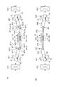
図1は、光スキャナーの全体構成を示す平面図である。図2(a)は、図1にA−Aで示した断面の断面図であり、図2(b)は、図1にB−Bで示した断面の断面図であり、図2(c)は、図1にC−Cで示した断面の断面図である。
図1および図2に示すように、光スキャナー1は、振動基板11と、基台12と、変位手段8と、を備えている。振動基板11は、4つの可動部201,202,203,204と、可動部201,202,203,204に支持される光反射部材20と、4つの可動部201,202,203,204のそれぞれにそれぞれ連結する4つの連結部4,5,6,7と、連結部4,5,6,7が連結されている固定部13とを備えている。振動基板11は、基台12に支持されている。可動部201,202,203,204は、変位手段8によって変位させられる。以下、光スキャナー1の各構成について順次詳細に説明する。
<First Embodiment>
An optical scanner according to a first embodiment relating to an optical scanner, an optical scanner manufacturing method, and an image forming apparatus will be described with reference to FIGS. 1 and 2.
FIG. 1 is a plan view showing the overall configuration of the optical scanner. 2 (a) is a cross-sectional view taken along the line AA in FIG. 1, and FIG. 2 (b) is a cross-sectional view taken along the line BB in FIG. ) Is a cross-sectional view taken along the line CC in FIG.
As shown in FIGS. 1 and 2, the optical scanner 1 includes a
(1−1.振動基板11)
第1実施形態では、光反射部材20を除く振動基板11(すなわち、可動部201,202,203,204、4つの固定部13、および4つの連結部4,5,6,7)は、SOI基板の不要部位をドライエッチングおよびウェットエッチング等の各種エッチング法により除去することにより一体的に形成されている。
(1-1. Vibration substrate 11)
In the first embodiment, the
4つの固定部13は、それぞれ連結部4,5、連結部5,6、連結部6,7、又は連結部4,7に連結されている。4つの固定部13と4つの連結部4,5,6,7とにより、可動部201,202,203,204の周囲を囲むように設けられている。4つの固定部13のXY平面視形状は、矩形で図示したが、これに限定されず、例えば三角形、正方形等の多角形、円形または楕円形等であってもよい。また、4つの固定部13の形状は、それぞれ同一の大きさおよび同一の形状で図示したが、これに限るものではなく、適宜形状を決定することができる。
可動部201,202,203,204は、それぞれ、平板状をなしている。そして、可動部201,202,203,204には、支持部材23を介して光反射部材20が固定されている。光反射部材20は平板状をなし、光反射部材20の一方の面(基台12と反対側の面)21には、光反射性を有する光反射部22が形成されている。そして、支持部材23が接着剤により4つの可動部201,202,203,204に固定されることで、光反射部材20は、可動部201,202,203,204に支持される。光反射部22は、例えば、面21上に金、銀、アルミニウム等の金属膜などを蒸着等により形成することにより得られる。光反射部22の光を反射する面が、光反射面に相当する。
The four fixing
Each of the
なお、第1実施形態では、光反射部材20のXY平面視形状は、円形であるが、光反射部材20のXY平面視形状としては、特に限定されず、例えば三角形、長方形、正方形等の多角形、楕円形等であってもよい。
このような光反射部材20は、それぞれ、可動部201,202,203,204、及び、連結部4,5,6,7によって固定部13に連結されている。4つの連結部4,5,6,7は、光反射部材20の略XY平面視にて、光反射部材20の周方向に沿って等間隔、すなわち90度間隔で配置されている。
In the first embodiment, the shape of the
Such a
そして、4つの連結部4,5,6,7のうち、連結部4,6は、光反射部材20を介してX軸方向に対向しかつ光反射部材20に対して対称的に形成されており、連結部5,7は、光反射部材20を介してY軸方向に対向しかつ光反射部材20に対して対称的に形成されている。このような連結部4,5,6,7に連結された可動部201,202,203,204によって光反射部材20を支持することにより、光反射部材20を安定した状態で支持することができる。
Of the four connecting
4つの連結部4,5,6,7は、互いに同様の構成をなしている。
具体的には、連結部(第1の連結部)4は、可動部201と、変位部41と、可動梁42と、一対の駆動梁43とを有している。可動梁42は、変位部41と可動部201とを連結している。駆動梁43は、変位部41と固定部13とを連結している。
そして、連結部(第3の連結部)5は、可動部202と、変位部51と、可動梁52と、一対の駆動梁53とを有している。可動梁52は、変位部51と可動部202とを連結している。駆動梁53は、変位部51と固定部13とを連結している。
また、連結部(第2の連結部)6は、可動部203と、変位部61と、可動梁62と、一対の駆動梁63とを有している。可動梁62は、変位部61と可動部203とを連結している。駆動梁63は、変位部61と固定部13とを連結している。
同様に、連結部(第4の連結部)7は、可動部204と、変位部71と、可動梁72と、一対の駆動梁73とを有している。可動梁72は、変位部71と可動部204とを連結している。駆動梁73は、変位部71と固定部13とを連結している。
なお、前記「同様の構成」とは、連結部を構成する要素が共通しているということである。したがって、外形形状については一致している必要はない。
各連結部4,5,6,7をこのような構成とすることにより、連結部の構成が簡単となるとともに、光反射部材20の回動中心軸X1,Y1まわりの回動等をスムーズに行うことができる。
The four connecting
Specifically, the connecting portion (first connecting portion) 4 includes a
The connecting portion (third connecting portion) 5 includes a
Further, the connecting portion (second connecting portion) 6 includes a
Similarly, the connecting portion (fourth connecting portion) 7 includes a
The “similar configuration” means that the elements constituting the connecting portion are common. Therefore, it is not necessary for the outer shapes to match.
By configuring each of the connecting
以下、連結部4,5,6,7について具体的に説明するが、連結部4,5,6,7の構成は、互いに同様であるため、連結部4について代表して説明し、他の連結部5,6,7については、その説明を省略する。なお、連結部5,7は、光反射部材20のXY平面視にて、連結部4に対して90度回転した状態で配置されている。そのため、連結部5,7については、下記の連結部4の説明中の「Y軸方向」を「X軸方向」とし、「X軸方向」を「Y軸方向」とすることで説明することもできる。
Hereinafter, the connecting
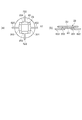
図3は、連結部の構成を示す斜視図である。
図3に示すように、一対の駆動梁43は、変位部41を介してY軸方向に対向配置されており、変位部41を両持ち支持している。また、一対の駆動梁43は、それぞれ、Y軸方向に延長する棒状をなしている。また、一対の駆動梁43は、駆動梁43の中心軸まわりに捩じり変形可能となっている。このような一対の駆動梁43は、同軸的に設けられており、この軸(以下、「回動中心軸Y2」とも言う)を中心として、一対の駆動梁43が捩じり変形するとともに変位部41が回動する。
FIG. 3 is a perspective view showing the configuration of the connecting portion.
As shown in FIG. 3, the pair of drive beams 43 are disposed to face each other in the Y-axis direction via the
変位部41は、可動部201に対してX軸方向に離間して設けられている。また、変位部41は、前述したように一対の駆動梁43によって両持ち支持されている。このような変位部41には内枠部411が形成されている。内枠部411は、変位部41の、光反射部材20の光反射面に平行な面の法線方向に沿って変位部41を貫通する貫通孔である。この内枠部411に永久磁石811が挿通されて、固定されている。永久磁石811は、例えば、嵌合(圧入)や、接着剤によって、変位部41に固定されている。
The
なお、変位部41の平面視形状としては、特に限定されず、例えば、三角形や正方形や五角形以上の多角形であってもよいし、円形であってもよい。
このような変位部41は、可動梁42によって可動部201と連結している。可動梁42は、全体的にX軸方向に延長するように設けられている。このような可動梁42は、変位部41と可動部201との間に設けられた屈曲部421と、可動部側可動梁422と、変位部側可動梁423とを有している。可動部側可動梁422は、屈曲部421と可動部201とを連結し、変位部側可動梁423は、屈曲部421と変位部41とを連結している。
可動部側可動梁422および変位部側可動梁423は、それぞれ、X軸方向に延長する棒状をなしている。また、可動部側可動梁422および変位部側可動梁423は、同軸的に設けられている。
In addition, it does not specifically limit as a planar view shape of the
Such a
The movable part side
これら2つの軸部のうちの変位部側可動梁423は、光スキャナー1の駆動時に大きな変形が起こらない硬さに設定されているのが好ましく、実質的に変形しない硬さに設定されているのがより好ましい。これに対して可動部側可動梁422は、その中心軸まわりに捩じり変形可能となっている。このように、可動梁42が実質的に変形しない硬い部分およびその先端側に位置する捩じり変形可能な部位を有することにより、可動部201をX軸およびY軸のそれぞれの軸まわりに安定して回動させることができる。なお、前記「変形しない」とは、Z軸方向への屈曲または湾曲および中心軸まわりの捩じり変形が実質的に起きないことを言う。
このような可動部側可動梁422および変位部側可動梁423は、屈曲部421を介して連結している。屈曲部421は、可動梁42が屈曲変形する際の節となる機能と、可動部側可動梁422の捩じり変形により発生するトルクを緩和(吸収)し、前記トルクが変位部側可動梁423に伝わるのを防止または抑制する機能とを有している。
Of these two shaft portions, the displacement portion side
Such a movable part side
図3に示すように、屈曲部421は、一対の変形部4211,4212と、これらの間に設けられた非変形部4213と、変形部4211を非変形部4213に接続する一対の接続部4214と、変形部4212を非変形部4213に接続する一対の接続部4215とを有している。
非変形部4213は、Y軸方向に延長する棒状をなしている。このような非変形部4213は、光スキャナー1の駆動時に実質的に変形しない硬さに設定されている。これにより、非変形部4213の回動中心軸Y4を中心に可動梁42を屈曲させることができ、屈曲部421に節としての機能を確実に発揮させることができ、光スキャナー1を安定して駆動させることができる。
As shown in FIG. 3, the
The
このような非変形部4213に対して対称的に一対の変形部4211,4212が配置されている。変形部4211,4212は、それぞれ、Y軸方向に延長する棒状をなしている。また、変形部4211,4212は、互いにX軸方向に離間して並設されている。このような変形部4211,4212は、それぞれ、その中心軸まわりに捩じり変形可能となっている。
A pair of
可動部201側に位置する変形部4211は、その長手方向のほぼ中央にて可動部側可動梁422の一端と連結しているとともに、その両端部にて一対の接続部4214を介して非変形部4213に連結している。同様に、変位部41側に位置する変形部4212は、その長手方向のほぼ中央にて変位部側可動梁423の一端と連結しているとともに、その両端部にて一対の接続部4215を介して非変形部4213に連結している。
The
一対の接続部4214の一方の接続部は、変形部4211および非変形部4213の一端部同士を連結し、他方の接続部は、変形部4211および非変形部4213の他端部同士を連結している。また、一対の接続部4215の一方の接続部は、変形部4212および非変形部4213の一端部同士を連結し、他方の接続部は、変形部4212および非変形部4213の他端部同士を連結している。
このような各接続部4214,4215は、X軸方向に延長する棒状をなしている。また、各接続部4214,4215は、Z軸方向に湾曲可能でかつその中心軸まわりに捩じり変形可能となっている。
以上、振動基板11の構成について具体的に説明した。
One connection portion of the pair of
Each of the
The configuration of the
前述したように、このような構成の振動基板11は、SOI基板から一体的に形成されている。これにより、振動基板11の形成が容易となる。具体的には、前述したように、振動基板11には、積極的に変形させる部位と、変形させない(変形させたくない)部位とが混在している。一方、SOI基板は、第1のSi層と、SiO2層と、第2のSi層とがこの順に積層した基板である。そこで、変形させない部位を前記3つの層の全てで構成するとともに、積極的に変形させる部位を第2のSi層のみで構成することにより、すなわち、SOI基板の厚さを異ならせることにより、変形させる部位と変形させない部位が混在する振動基板11を簡単に形成することができる。なお、積極的に変形させる部位は、第2のSi層とSiO2層の2層で構成されていてもよい。
As described above, the
前記「変形させる部位」には、駆動梁43,53,63,73、可動部側可動梁422,522,622,722、変形部4211,4212,5211,5212,6211,6212,7211,7212および接続部4214,4215,5214,5215,6214,6215,7214,7215が含まれる。
一方、前記「変形させない部位」には、可動部201,202,203,204、固定部13、変位部41,51,61,71、変位部側可動梁423,523,623,723および非変形部4213,5213,6213,7213が含まれる。
The “parts to be deformed” include drive beams 43, 53, 63, 73, movable part side
On the other hand, the “parts not to be deformed” include the
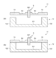
(1−2.基台12)
図2(a)に示す図1のA−A断面図のように、基台12は、平板状の基部121と、基部121の4隅に設けられた基板保持部122とを有している。このような基台12は、図2(c)に示す図1のC−C断面図のように、基板保持部122にて振動基板11の固定部13の下面と接合されている。これにより、基台12によって振動基板11が支持される。このような基台12は、例えば、パイレックス(登録商標)、テンパックスなどのガラスやシリコンあるいはアルミニウムを主材料として構成されている。なお、基台12と固定部13の接合方法としては、特に限定されず、例えば接着剤を用いて接合してもよく、陽極接合等の各種接合方法を用いてもよい。また、基台12は、4隅に基板保持部122を有するとしたが、これに限定されず、基板保持部122は、振動基板11の固定部13の位置に対応して基部121上に設けられていればよい。
(1-2. Base 12)
As shown in the AA cross-sectional view of FIG. 1 shown in FIG. 2A, the
(1−3.変位手段8)
図1に示すように、変位手段8は、第1の変位手段81と、第2の変位手段82と、第3の変位手段83と、第4の変位手段84とを有している。
第1の変位手段81は、永久磁石811、コイル812が巻き付けられた駆動部810、および電源813を有している。第2の変位手段82は、永久磁石821、コイル822が巻き付けられた駆動部820、および電源823を有している。第3の変位手段83は、永久磁石831、コイル832が巻き付けられた駆動部830、および電源833を有している。第4の変位手段84は、永久磁石841、コイル842が巻き付けられた駆動部840、および電源843を有している。
(1-3. Displacement means 8)
As shown in FIG. 1, the
The first displacement means 81 includes a
そして、第1の変位手段81は、連結部4に対応して設けられており、第2の変位手段82は、連結部5に対応して設けられており、第3の変位手段83は、連結部6に対応して設けられており、第4の変位手段84は、連結部7に対応して設けられている。
このような構成によれば、変位手段8の構成が簡単となる。また、変位手段8を電磁駆動とすることにより、比較的大きな力を発生させることができ、光反射部材20をより確実に回動させることができる。また、各連結部4,5,6,7に1つの変位手段8(81,82,83,84)が設けられているため、各連結部4,5,6,7を独立して変形させることができる。そのため、光反射部材20を様々な態様で変位させることができる。
The first displacement means 81 is provided corresponding to the connecting
According to such a structure, the structure of the displacement means 8 becomes simple. Moreover, by making the displacement means 8 electromagnetically drive, a comparatively big force can be generated and the
以下、第1の変位手段81、第2の変位手段82、第3の変位手段83および第4の変位手段84について説明するが、これらはそれぞれ同様の構成であるため、以下では、第1の変位手段81について代表して説明し、第2の変位手段82、第3の変位手段83および第4の変位手段84については、その説明を省略する。なお、第2の変位手段82および第4の変位手段84は、光反射部材20の平面視にて、第1の変位手段81に対して90度回転した状態で配置されている。そのため、第2の変位手段82および第4の変位手段84については、下記の第1の変位手段81の説明中の「Y軸方向」を「X軸方向」とし、「X軸方向」を「Y軸方向」とすることで説明することもできる。
Hereinafter, the first displacement means 81, the second displacement means 82, the third displacement means 83, and the fourth displacement means 84 will be described. Since these have the same configuration, the first displacement means 81 will be described below. The displacement means 81 will be described as a representative, and the description of the second displacement means 82, the third displacement means 83, and the fourth displacement means 84 will be omitted. The second displacing means 82 and the fourth displacing means 84 are arranged in a state of being rotated 90 degrees with respect to the first displacing means 81 in a plan view of the
図3および図4に示すように、永久磁石811は、棒状をなしており、その長手方向に磁化している。すなわち、永久磁石811は、その長手方向の一端側がS極となっており、他端側がN極となっている。このような永久磁石811は、変位部41に形成された内枠部411に挿通されており、長手方向のほぼ中央で変位部41に固定されている。そして、永久磁石811が、変位部41の上下に同じ長さだけ突出し、かつ変位部41(回動中心軸Y2)を介してS極とN極が対向する。これにより、光反射部材20を安定して変位させることができる。
As shown in FIGS. 3 and 4, the
また、永久磁石811は、その長手方向が変位部41の面方向に直交するように設けられている。また、永久磁石811は、その中心軸が回動中心軸Y2と交わるように設けられている。
このような永久磁石811としては、特に限定されず、例えば、ネオジウム磁石、フェライト磁石、サマリウムコバルト磁石、アルニコ磁石、ボンド磁石などの、硬磁性体を着磁したものを好適に用いることができる。
The
The
なお、第1実施形態では、永久磁石811は、棒状をなしているが、永久磁石の形状としては、特に限定されず、例えば、板状または円柱状をなしていてもよい。この場合には、永久磁石811を面方向に磁化し、その面方向がX軸方向と直交するように変位部41に固定すればよい。これにより、永久磁石811のX軸方向長さを短くすることができるため、変位部41の回動に伴って発生する慣性モーメントを抑えることができる。
In addition, in 1st Embodiment, although the
コイル812は、永久磁石811に作用する磁界を発生する。このようなコイル812は、振動基板11の外側近傍に、X軸方向にて永久磁石811と対向するように配置されている。また、コイル812は、X軸方向の磁界を発生させることができるように、すなわち、コイル812の永久磁石811側がN極となりその反対側がS極となる状態と、コイル812の永久磁石811側がS極となりその反対側がN極となる状態とを発生させることができるように設けられている。
The
第1実施形態の光スキャナー1は、振動基板11の外側に基台12と固定的に設けられた駆動部810(820,830,840)にコイル固定部85を有しており、このコイル固定部85が有するX軸方向に延長する突出部851にコイル812が巻き付けられている。このような構成とすることにより、コイル812を振動基板11に対して固定でき、かつ、簡単に前述のような磁界を発生させることができる。また、突出部851を鉄などの軟磁性体で構成することにより、突出部851をコイル812の磁心として用いることができ、前述のような磁界をより効率的に発生させることもできる。
The optical scanner 1 according to the first embodiment includes a
電源813は、コイル812に電気的に接続されている。そして、電源813からコイル812に所望の電圧を印加することにより、コイル812から前述したような磁界を発生させることができる。第1実施形態では、電源813は、交番電圧および直流電圧を選択して印加できるようになっている。また、交番電圧を印加する際には、その強さ、周波数を変更できるようになっており、さらにオフセット電圧(直流電圧)を重畳させることもできるようになっている。
The
(2.光スキャナー1の作動)
次いで、光スキャナーの作動について説明する。
上述のような構成の光スキャナー1では、光反射部材20を回動させるパターンと、光反射部材20を振動させるパターンと、光反射部材20を所定位置で静止させるパターンとを選択することができるようになっている。このように、光スキャナー1が種々のパターンで駆動することができるのは、各連結部4,5,6,7の可動梁42,52,62,72を屈曲変形させることにより得られる効果である。
以下、これら3つのパターンについて順次説明する。なお、以下では、説明の便宜上、永久磁石811,821,831,841が全てN極を上側にして配置された構成について代表して説明する。
(2. Operation of optical scanner 1)
Next, the operation of the optical scanner will be described.
In the optical scanner 1 configured as described above, a pattern for rotating the
Hereinafter, these three patterns will be described sequentially. In the following, for the convenience of explanation, a configuration in which the
(2−1.回動)
<Y軸まわりの回動>
図5に基づいて、光反射部材20のY軸まわりの回動について説明する。なお、図5は、図1中A−A線断面図に対応する断面図である。
まず、コイル812の永久磁石811側がN極、コイル832の永久磁石831側がS極となる第1の状態と、コイル812の永久磁石811側がS極、コイル832の永久磁石831側がN極となる第2の状態とが交互にかつ周期的に切り替わるように、電源813,833からコイル812,832に交番電圧を印加する。電源813,833からコイル812,832に印加される交番電圧は、互いに同じ波形(強さおよび周波数が同じ)であるのが好ましい。
(2-1. Rotation)
<Rotation around Y axis>
Based on FIG. 5, the rotation of the
First, the first state in which the
図5(a)に示す第1の状態では、永久磁石811のS極がコイル812に引き付けられるとともにN極がコイル812から遠ざかって傾斜するため、一対の駆動梁43を捩じり変形させつつ、変位部41がその上面を光反射部材20側に向けるように回動中心軸Y2まわりに傾斜する。これとともに、永久磁石831のN極がコイル832に引き付けられるとともにS極がコイル832から遠ざかって傾斜するため、一対の駆動梁63を捩じり変形させつつ、変位部61がその下面を光反射部材20側に向けるように回動中心軸Y3まわりに傾斜する。すなわち、変位部41,61がともに図5(a)中時計回りに傾斜する。
In the first state shown in FIG. 5A, since the south pole of the
この変位部41,61の傾斜とともに、変位部側可動梁423が光反射部材20側の端を下側に向けるように傾斜し、変位部側可動梁623が光反射部材20側の端を上側に向けるように傾斜する。これにより、変位部側可動梁423,623の光反射部材20側の端同士がZ軸方向にずれた状態となる。
そして、変位部側可動梁423,623の光反射部材20側の端同士がZ軸方向にずれることによって、変形部4211,4212,6211,6212をその中心軸まわりに捩じり変形させるとともに各接続部4214,4215,6214,6215を湾曲変形させながら、可動部側可動梁422,622および光反射部材20が一体的に図5(a)中反時計回りに傾斜する。
Along with the inclination of the
Then, the ends of the
このように、第1の状態では、連結部4の可動梁42がその途中にある屈曲部421で下側に凸のV字状に屈曲変形(第1の変形)するとともに、連結部6の可動梁62がその途中にある屈曲部621で上側に凸のV字状に屈曲変形(第2の変形)することにより、回動中心軸Y1を中心として、光反射部材20が図5(a)中反時計回りに傾斜する。
In this way, in the first state, the
一方、図5(b)に示す第2の状態では、前述した第1の状態と逆の変形が起こる。すなわち、第2の状態では、連結部4の可動梁42が屈曲部421で上側に凸のV字状に屈曲変形(第2の変形)するとともに、連結部6の可動梁62が屈曲部621で下側に凸のV字状に屈曲変形(第1の変形)する。これにより、回動中心軸Y1を中心として、光反射部材20が図5(b)中時計回りに傾斜する。
On the other hand, in the second state shown in FIG. 5B, the deformation opposite to the first state described above occurs. That is, in the second state, the
このような第1の状態と、第2の状態とを交互にかつ周期的に切り替えることによって、光反射部材20を回動中心軸Y1まわりに回動させることができる。なお、光反射部材20の回動中心軸Y1まわりの回動は、連結部5,7が有する可動部側可動梁522,722がその中心軸まわりに捩じり変形することによって許容される。
なお、コイル812,832に印加する交番電圧の周波数としては特に限定されず、光反射部材20、4つの可動部201,202,203,204、および連結部4,5,6,7で構成される振動基板11の共振周波数と等しくても異なっていてもよいが、前記共振周波数と異なっているのが好ましい。すなわち、光スキャナー1を非共振で駆動するのが好ましい。これにより、光スキャナー1のより安定した駆動が可能となる。
By alternately and periodically switching between the first state and the second state, the
The frequency of the alternating voltage applied to the
<X軸まわりの回動>
次いで、図6に基づいて、光反射部材20のX軸まわりの回動について説明する。なお、図6は、図1中B−B線断面図に対応する断面図である。
まず、コイル822の永久磁石821側がN極、コイル842の永久磁石841側がS極となる第1の状態と、コイル822の永久磁石821側がS極、コイル842の永久磁石841側がN極となる第2の状態とが交互にかつ周期的に切り替わるように、電源823,843からコイル822,842に交番電圧を印加する。電源823,843からコイル822,842に印加される交番電圧は、互いに同じ波形であるのが好ましい。
<Rotation around X axis>
Next, the rotation of the
First, the first state in which the
前述した光反射部材20の回動中心軸Y1まわりの回動と同様に、図6(a)に示す第1の状態では、連結部5の可動梁52がその途中にある屈曲部521で下側に凸のV字状に屈曲変形(第1の変形)するとともに、連結部7の可動梁72がその途中にある屈曲部721で上側に凸のV字状に屈曲変形(第2の変形)することにより、回動中心軸X1を中心として、光反射部材20が図6(a)中反時計回りに傾斜する。
Similar to the rotation of the
一方、図6(b)に示す第2の状態では、前述した第1の状態と逆の変形が起こる。すなわち、第2の状態では、連結部5の可動梁52が屈曲部521で上側に凸のV字状に屈曲変形(第2の変形)するとともに、連結部7の可動梁72が屈曲部721で下側に凸のV字状に屈曲変形(第1の変形)することにより、回動中心軸X1を中心として、光反射部材20が図6(b)中時計回りに傾斜する。
このような第1の状態と、第2の状態とを交互にかつ周期的に切り替えることによって、光反射部材20を回動中心軸X1まわりに回動させることができる。なお、光反射部材20の回動中心軸X1まわりの回動は、連結部4,6が有する可動部側可動梁422,622がその中心軸まわりに捩じり変形することにより許容される。
On the other hand, in the second state shown in FIG. 6B, the deformation opposite to the first state described above occurs. That is, in the second state, the
By alternately and periodically switching between the first state and the second state, the
なお、コイル822,842に印加する交番電圧の周波数としては特に限定されず、光反射部材20、4つの可動部201,202,203,204、および連結部4,5,6,7で構成される振動基板11の共振周波数と等しくても異なっていてもよいが、前記共振周波数と異なっているのが好ましい。すなわち、光スキャナー1を非共振で駆動するのが好ましい。これにより、光スキャナー1のより安定した駆動が可能となる。
The frequency of the alternating voltage applied to the
<X軸およびY軸のそれぞれの軸まわりの回動>
前述したようなX軸まわりの回動と、Y軸まわりの回動とを同時に行うことにより、光反射部材20を回動中心軸Y1および回動中心軸X1のそれぞれの軸まわりに2次元的に回動させることができる。前述したように、光反射部材20の回動中心軸Y1まわりの回動は、可動部側可動梁522,722がその中心軸まわりに捩じり変形することによって許容され、光反射部材20の回動中心軸X1まわりの回動は、可動部側可動梁422,622がその中心軸まわりに捩じり変形することにより許容される。
<Rotation around X axis and Y axis>
By simultaneously performing the rotation about the X axis and the rotation about the Y axis as described above, the
前述したX軸まわりの回動、Y軸まわりの回動およびこれら2軸まわりの回動では、コイル812,822,832,842に印加する交番電圧の周波数としては特に限定されず、光反射部材20、4つの可動部201,202,203,204、および連結部4,5,6,7で構成される振動基板11の共振周波数と等しくても異なっていてもよいが、前記共振周波数と異なっているのが好ましい。すなわち、光スキャナー1を非共振で駆動するのが好ましい。これにより、光スキャナー1のより安定した駆動が可能となる。
In the above-described rotation around the X axis, rotation around the Y axis, and rotation around these two axes, the frequency of the alternating voltage applied to the
また、光反射部材20を回動中心軸Y1まわりに回動させるためにコイル812,832に印加する交番電圧の周波数と、光反射部材20を回動中心軸X1まわりに回動させるためにコイル822,842に印加する交番電圧の周波数とは等しくてもよいし異なっていてもよい。例えば、光反射部材20を回動中心軸X1よりも回動中心軸Y1まわりに速く回動させたい場合には、コイル812,832に印加する交番電圧の周波数を、コイル822,842に印加する交番電圧の周波数よりも高く設定すればよい。
The frequency of the alternating voltage applied to the
また、コイル812,832に印加する交番電圧の強さと、コイル822,842に印加する交番電圧の強さは、等しくても異なっていてもよい。例えば、光反射部材20を回動中心軸X1よりも回動中心軸Y1まわりに大きく回動させたい場合には、コイル812,832に印加する交番電圧の強さを、コイル822,842に印加する交番電圧の強さよりも強くすればよい。
Further, the strength of the alternating voltage applied to the
上記では、コイル812,822,832,842に交番電圧を印加する駆動方法について説明したが、次のような駆動方法によっても光反射部材20を回動させることができる。すなわち、電源813,823,833,843からコイル812,822,832,842に印加される交番電圧に(+)または(−)のオフセット電圧(直流電圧)を重畳してもよい。言い換えれば、永久磁石811,821,831,841のN極がコイル812,822,832,842に引き付けられる強さ(以下、単に「N極引き付け強さ」とも言う)と、永久磁石811,821,831,841のS極がコイル812,822,832,842に引き付けられる強さ(以下、単に「S極引き付け強さ」とも言う)とを異ならせてもよい。
In the above description, the driving method for applying the alternating voltage to the
以下、具体的に説明するが、前述したような、N極引き付け強さおよびS極引き付け強さが等しい状態を「通常状態」と言う。
コイル812,822,832,842のS極引き付け強さがN極引き付け強さよりも大きい場合には、通常状態と比較して、図1のA−A断面から見た変位部41,51,61,71の光反射部材20側の端部における回動の上死点および下死点(回動方向が切り替わる点)が下側に移動する。その結果、図7に示すように、光反射部材20の回動中心軸X1,Y1が通常状態に比べて下側に移動する。逆に、コイル812,822,832,842のS極引き付け強さがN極引き付け強さよりも弱い場合には、通常状態と比較して、図1のA−A断面から見た変位部41,51,61,71の回動の上死点および下死点がそれぞれ上側に移動する。このため、光反射部材20の回動中心軸X1,Y1が通常状態に比べて上側に移動する。
Hereinafter, although specifically described, a state in which the N-pole attracting strength and the S-pole attracting strength are equal as described above is referred to as a “normal state”.
When the S-pole attracting strength of the
このように、電源813,823,833,843からコイル812,822,832,842に印加される交番電圧にオフセット電圧を重畳することにより、光反射部材20の回動中心軸X1,Y1をZ軸方向にずらすことができる。これにより、例えば、光スキャナー1がプロジェクター等の画像形成装置に組み込まれている場合に、画像形成装置を組み立てた後でも、光源から出射される光の光反射部材20までの光路長を調整することができる。すなわち、画像形成装置の組み立て時には、光源と光反射部材20との位置決めを精密に行うが、仮にこれらの位置が設定値に対してずれてしまった場合でも、組み立て後に、光源と光反射部材20との位置を補正することができる。
In this way, by rotating the offset voltage on the alternating voltage applied to the
(2−2.振動)
まず、コイル812,822,832,842の永久磁石811,821,831,841側がそれぞれN極となる第1の状態と、コイル812,822,832,842の永久磁石811,821,831,841側がそれぞれS極となる第2の状態とが、交互にかつ周期的に切り替わるように、電源813,823,833,843からコイル812,822,832,842に交番電圧を印加する。電源813,823,833,843からコイル812,822,832,842に印加される交番電圧は、互いに同じ波形であるのが好ましい。
(2-2. Vibration)
First, the first state in which the
図8(a)に示す第1の状態では、前述した回動の場合と同様にして、変位部41,51,61,71は、それぞれ、その上面を光反射部材20側に向けるように回動中心軸Y2,X2,Y3,X3まわりに傾斜する。このような変位部41,51,61,71の傾斜に伴って、変位部側可動梁423,523,623,723は、それぞれ、光反射部材20側の端が下側を向くように傾斜する。これにより、可動梁42,52,62,72が屈曲部421,521,621,721で屈曲しながら、可動部側可動梁422,522,622,722および光反射部材20が一体的にかつ光反射部材20の姿勢(すなわち面方向)を一定に保ちつつ下側に移動する。
In the first state shown in FIG. 8A, the
一方、図8(b)に示す第2の状態では、変位部41,51,61,71は、それぞれ、その下面を光反射部材20側に向けるように回動中心軸Y2,X2,Y3,X3まわりに傾斜する。このような変位部41,51,61,71の傾斜に伴って、変位部側可動梁423,523,623,723は、それぞれ、光反射部材20側の端が上側を向くように傾斜する。これにより、可動梁42,52,62,72が屈曲部421,521,621,721で屈曲しながら、可動部側可動梁422,522,622,722および光反射部材20が一体的にかつ光反射部材20の姿勢を一定に保ちつつ上側に移動する。
On the other hand, in the second state shown in FIG. 8 (b), the
このような第1の状態と、第2の状態とを交互に切り替えることによって、光反射部材20をその姿勢を保ちつつ、すなわち光反射部22の表面をX−Y平面と平行に保ちつつ、Z軸方向に振動させることができる。
なお、コイル812,822,832,842に印加する交番電圧の周波数としては特に限定されず、光反射部材20、4つの可動部201,202,203,204、および連結部4,5,6,7で構成される振動基板11の共振周波数と等しくても異なっていてもよいが、前記共振周波数と等しいのが好ましい。すなわち、光スキャナー1を共振で駆動するのが好ましい。これにより、光スキャナー1のより安定した駆動が可能となる。
このような振動パターンでも、前述した回動パターンと同様に、コイル812,822,832,842に印加する交番電圧にオフセット電圧を重畳させることにより、自然状態からZ軸方向にシフトして光反射部材20を振動させることができる。
By alternately switching between the first state and the second state, the
The frequency of the alternating voltage applied to the
Even in such a vibration pattern, similarly to the rotation pattern described above, the offset voltage is superimposed on the alternating voltage applied to the
(2−3.静止パターン)
例えば、コイル812,822,832,842の永久磁石811,821,831,841側がそれぞれN極となる状態となるように電源813,823,833,843からコイル812,822,832,842に直流電圧を印加する。電源813,823,833,843からコイル812,822,832,842に印加される直流電圧は、互いに同じ強さであるのが好ましい。このような電圧をコイル812,822,832,842に印加すると図8(a)に示すような状態で光反射部材20が静止する。
(2-3. Static pattern)
For example, direct current is supplied from the
逆に、コイル812,822,832,842の永久磁石811,821,831,841側がそれぞれS極となる状態となるように電源813,823,833,843からコイル812,822,832,842に直流電圧を印加すると、図8(b)に示すような状態で光反射部材20が静止する。
このように、光反射部材20を自然状態とは異なる位置に維持することができる。このような駆動によれば、例えば光反射部22で反射した光の光路を自然状態のときに対してずらすことができるため、例えば、光スキャナー1を光スイッチとして利用するときに特に有効である。
Conversely, the
Thus, the
また、例えば、光スキャナー1がプロジェクター等の画像形成装置に組み込まれている場合に、光源から異常なレーザーが出射されるなどの理由から、レーザーの装置外部への出射を停止しなければならない場合に、光反射部材20を自然状態とは異なる位置(レーザーの光路と交わらない位置)に退避させることにより、光反射部22によるレーザーの反射を防止する。これにより、装置外部へのレーザーの出射を防止することができる。また、光反射部材20を変位させることにより光反射部22で反射されたレーザーの光路を変更することにより、装置外部へのレーザーの出射を防止してもよい。これにより、このような問題を解決するための安全機構を別途組み込まなくてもよくなり、画像形成装置の製造工程が簡易化されるとともに、製造コストを削減することができる。
In addition, for example, when the optical scanner 1 is incorporated in an image forming apparatus such as a projector, the emission of the laser to the outside of the apparatus has to be stopped because an abnormal laser is emitted from the light source. Further, the
このような光反射部材20の静止駆動を応用し、コイル812,822,832,842に印加する直流電圧の強さを互いに異ならせることにより、光反射部材20を自然状態に対して傾けた状態で維持することもできる。また、コイル812,822,832,842に印加する直流電圧の強さを、それぞれ独立して、かつ経時的に変化させることにより、光反射部材20を連続的または段階的に不規則に変位させることもできる。このような駆動方法は、例えば、光反射部22で反射した光をベクタースキャンする時に特に有効である。
以上、光スキャナー1の駆動について詳細に説明した。
A state in which the
The driving of the optical scanner 1 has been described in detail above.
このような光スキャナー1では、光反射部材20の回動中心軸Y1まわりの回動と回動中心軸X1まわりの回動とを同じ機構で行うことができる。また、光スキャナー1では、光反射部材20の回動中心軸Y1まわりの回動と回動中心軸X1まわりの回動とを独立して行うことができる。すなわち、光スキャナー1では、回動中心軸Y1の回動が回動中心軸X1まわりの回動に影響を受けず、逆に、回動中心軸X1の回動も回動中心軸Y1まわりの回動に影響を受ない。そのため、光スキャナー1によれば、回動中心軸Y1および回動中心軸X1のそれぞれの軸まわりに光反射部材20を安定して回動させることができる。
In such an optical scanner 1, the
また、前述したように、光スキャナー1では、光反射部材20の回動中心軸Y1まわりの回動は、可動部側可動梁522,722がその中心軸まわりに捩じり変形することによって許容され、光反射部材20の回動中心軸X1まわりの回動は、可動部側可動梁422,622がその中心軸まわりに捩じり変形することにより許容される。このように、各連結部4,5,6,7が中心軸まわりに捩じり変形可能な可動部側可動梁422,522,622,722を有しているため、光反射部材20を回動中心軸Y1,X1のそれぞれの軸まわりにスムーズに回動させることができる。
Further, as described above, in the optical scanner 1, the rotation of the
また、光スキャナー1では、連結部4において、前述のように捩じり変形する可動部側可動梁422と変形させたくない変位部側可動梁423との間に屈曲部421を設けている。そのため、前述の捩じり変形により生じた応力は、屈曲部421の変形部4211,4212や接続部4214,4215が変形することにより吸収・緩和され、変位部側可動梁423に伝わらない。すなわち、屈曲部421を設けることにより、光反射部材20の回動中に変位部側可動梁423がその中心軸まわりに捩じり変形してしまうのを確実に防止することができる。このことは、連結部4以外の他の連結部5,6,7についても同様である。そのため、光反射部材20を回動中心軸Y1,X1のそれぞれの軸まわりにスムーズに回動させることができる。
Further, in the optical scanner 1, the bending
さらには、各変位部側可動梁423,523,623,723の破壊が効果的に防止される。すなわち、棒状の部材において、自然状態からZ軸方向の応力が加わったときの破壊強度よりも、中心軸まわりの捩じり変形が生じている状態からZ軸方向の応力が加わったときの破壊強度の方が低いことが技術的に明らかになっている。そのため、上述のように、屈曲部421,521,621,721を設け、変位部側可動梁423,523,623,723に捩じり変形を生じさせないことにより、変位部側可動梁423,523,623,723の破壊を効果的に防止することができる。
Furthermore, destruction of each displacement part side movable beam 423,523,623,723 is effectively prevented. In other words, in a rod-shaped member, the fracture when the stress in the Z-axis direction is applied from the state in which torsional deformation around the central axis occurs rather than the fracture strength when the stress in the Z-axis direction is applied from the natural state. It is technically clear that the strength is lower. Therefore, as described above, the bending
また、連結部4において、変位部側可動梁423が実質的に変形しないため、変位部41の回動によって生じる応力を効率よく光反射部材20の回動に用いることができる。このことは連結部5,6,7についても同様である。そのため、光反射部材20を大きい回動角度でしかも省電力で回動させることができたり、大きい振幅でZ軸方向に振動させたりすることができる。
Further, since the displacement part side
また、連結部4において、屈曲部421が非変形部4213を有しているため、この非変形部4213を軸にして可動梁42を屈曲させることができる。このことは、連結部5,6,7についても同様である。そのため、各連結部4,5,6,7の可動梁42,52,62,72を簡単かつ確実に屈曲させることができ、光反射部材20を安定して回動、振動させることができる。
Further, in the connecting
また、連結部4において、屈曲部421が可動部側可動梁422と連結する変形部4211と、変位部側可動梁423と連結する変形部4212とを有し、可動梁42の屈曲時に、変形部4211,4212がその中心軸まわりに捩じり変形することにより、屈曲により発生する応力を効果的に緩和している。このことは、連結部5,6,7についても同様である。そのため、各連結部4,5,6,7の可動梁42,52,62,72を確実に屈曲させることができるとともに、可動梁42,52,62,72の破壊を防止することができる。すなわち、光スキャナー1を安定して駆動することができる。
Further, the connecting
また、連結部4において、屈曲部421が一対の変形部4211,4212を有しているため、次のような効果も発揮することができる。すなわち、例えば、通電によりコイル812から発生する熱や光反射部22に照射される光によって生じる熱等による可動部側可動梁422および変位部側可動梁423の熱膨張を、変形部4211,4212が変形することにより許容することができる。このことは、連結部5,6,7についても同様である。そのため、光スキャナー1は、振動基板11に応力が残留してしまうのを防止または抑制することができ、温度によらずに所望の振動特性を発揮することができる。
Moreover, in the
また、光スキャナー1は、変位部41,51,61,71を駆動する駆動部810,820,830,840が、可動梁42,52,62,72の延長方向に変位部41,51,61,71から隔てて配置され、変位部41,51,61,71の内枠部411に固定される永久磁石811,821,831,841に近付けて配置することができる。
このため、永久磁石811,821,831,841により駆動部810,820,830,840に発生させるトルクを高い状態にすることができる。トルクは磁界に比例し、コイルにより発生する磁界は電流に比例するので、同一のトルクを発生させることは、駆動部810,820,830,840が永久磁石811,821,831,841に近付けて配置されることにより、低い電流で可能となる。そして、消費電力Wは、W=I2×R(Wは消費電力、Iは電流、Rは抵抗を示す)であらわされるように、電流の2乗に比例するので、変位部41,51,61,71を駆動する駆動部810,820,830,840の消費電力を低くすることができ、消費電力化を実現する光スキャナー1を得ることができる。たとえば、駆動部810,820,830,840と永久磁石811,821,831,841との距離を、従来に比べて1/4にすると、同一トルクを発生させるために、従来比1/4の電流、および従来比1/16の消費電力で、光スキャナー1を安定して駆動させることができる。
In the optical scanner 1, the
For this reason, the torque generated in the
次に、支持部材23の形状について、図9を参照して説明する。図9は、支持部材の形状を示す説明図である。図9(a)は、図1の4つの可動部と支持部材を図1の裏面側から表示した図である。図9(b)は、図9(a)においてX1軸を含む断面における断面図である。
Next, the shape of the
図9(a)、及び図9(b)に示すように、支持部材23は矩形の固着面を有する柱状部材である。固着面の矩形形状のX軸方向の寸法は、可動部201の可動部側可動梁422側の辺と可動部203の可動部側可動梁622側の辺との距離よりも小さい。また、固着面の矩形形状のY軸方向の寸法は、可動部202の可動部側可動梁522側の辺と可動部204の可動部側可動梁722側の辺との距離よりも小さい。
図9(a)、及び図9(b)に示すように、4つの可動部201,202,203,204と支持部材23を固着する。このとき、図9(a)のX1軸とY1軸との交点(XY平面視で可動部201,202,203,204間の中心位置)と支持部材23の固着面の中心位置とが概ね同一位置となるように、可動部201,202,203,204と支持部材23を固着する。このため、支持部材23は、可動部201,202,203,204とは接着剤を介して接するが、可動梁42,52,62,72とは接しないように配置される。
As shown in FIGS. 9A and 9B, the
As shown in FIG. 9A and FIG. 9B, the four
支持部材23は、可動部201,202,203,204とは接着剤を介して接するが、可動部側可動梁422,522,622,722とは接しないため、可動梁の長さを変えることがない。これにより、可動梁のばね定数を一定に保つことができ、安定して駆動させることが出来る。また、可動梁との接触による破損を防ぐことが出来る。
The
次に、支持部材23とは異なる形状を有する支持部材の例について、図9(c)、図9(d)、図9(e)、及び図9(f)、を参照して説明する。図9(c)は、4つの可動部と支持部材を支持部材の側から観た図である。図9(d)は、図9(c)においてX1軸を含む断面における断面図である。図9(e)は、4つの可動部と支持部材を支持部材の側から観た図である。図9(f)は、図9(e)においてX1軸を含む断面における断面図である。
Next, an example of a support member having a shape different from that of the
図9(c)、及び図9(d)に示すように、支持部材24は、可動部201,202,203,204と固着する固着面24bの外周側に、斜面24aが形成されている。斜面24aは、固着面24bの外周側から支持部材24の外周側に向かって、光反射部22側に傾斜している。
As shown in FIG. 9C and FIG. 9D, the
図9(e)及び図9(f)に示すように、支持部材25は、可動部201,202,203,204と固着する固着面25bに、凹部25aが、4個所形成されている。凹部25aは、支持部材25が可動部201,202,203,204と固着された状態で、可動部側可動梁422、可動部側可動梁522、可動部側可動梁622、又は可動部側可動梁722と対向する位置に形成されている。凹部25aの平面形状は、可動部側可動梁422、可動部側可動梁522、可動部側可動梁622、又は可動部側可動梁722の平面形状より大きく、形成されている。したがって、支持部材25において、可動部側可動梁422、可動部側可動梁522、可動部側可動梁622、又は可動部側可動梁722には、凹部25aが臨んでおり、固着面25bは、可動部側可動梁422、可動部側可動梁522、可動部側可動梁622、及び可動部側可動梁722とは接触しない。
As shown in FIGS. 9 (e) and 9 (f), the
支持部材24及び支持部材25は、可動梁42、可動梁52、可動梁62、及び可動梁72の可動部側可動梁422、可動部側可動梁522、可動部側可動梁622、及び可動部側可動梁722と接しない。このため、可動梁42、可動梁52、可動梁62、及び可動梁72の長さを変えることがない。これにより、可動梁42、可動梁52、可動梁62、及び可動梁72のばね定数を一定に保つことができ、安定して駆動させることが出来る。また、支持部材24又は支持部材25と可動梁42、可動梁52、可動梁62、又は可動梁72との接触による、支持部材24、支持部材25、可動梁42、可動梁52、可動梁62、又は可動梁72の破損を抑制することが出来る。
The
次に、上述した支持部材23などとは異なる形状を有する支持部材の例について、図10を参照して説明する。図10は、支持部材の形状を示す説明図である。図10(a)、図10(c)、及び図10(e)は、4つの可動部と支持部材を支持部材の側から観た図である。図10(b)、図10(d)、及び図10(f)は、それぞれ図10(a)、図10(c)、又は図10(e)において、X1軸を含む断面における断面図である。
Next, an example of a support member having a shape different from the above-described
図10(a)、及び図10(b)に示すように、4つの可動部201,202,203,204と支持部材26を固着する。支持部材26の可動部201,202,203,204との接着面側には、可動部201,202,203,204と係合する形状を有する凹部261、凹部262、凹部263、及び凹部264が設けられている。4つの凹部261,262,263,264に可動部201,202,203,204が係合して、接着剤によって固着されている。
As shown in FIG. 10A and FIG. 10B, the four
支持部材26の構成によれば、支持部材26と、可動部201,202,203,204とを容易に位置合わせすることが出来る。また、支持部材26は、可動梁42,52,62,72とは接しないため、可動梁の長さを変えることがない。これにより、可動梁のばね定数を一定に保つことができ、安定して駆動させることが出来る。また、可動梁との接触による破損を防ぐことが出来る。
According to the configuration of the
以下、支持部材26の凹部261、凹部262、凹部263、及び凹部264とは異なる形状を有し、可動部201、可動部202、可動部203、又は可動部204と係合する凹部を備える、支持部材27及び支持部材28について記載する。
Hereinafter, the
図10(c)、及び図10(d)に示すように、支持部材27は、凹部271、凹部272、凹部273、及び凹部274を備えている。凹部271,272,273,274のXY平面視形状は、一部の辺が円弧を有する形状である。このとき、可動部201,202,203,204のXY平面視形状は、各凹部と略同一形状の形状が望ましい。もちろん、凹部271,272,273,274は、上記の形状に限定されず、半円形、半楕円形であってもよく、可動部201,202,203,204は、三角形、正方形や五角形以上の多角形であっても良い。
As shown in FIG. 10C and FIG. 10D, the
図10(e)、及び図10(f)に示すように、支持部材28は、凹部281、凹部282、凹部283、及び凹部284を備えている。凹部281,282,283,284のXY平面視形状は、台形である。このとき、可動部201,202,203,204のXY平面視形状は、各凹部と略同一形状の台形が望ましい。もちろん、凹部281,282,283,284は、台形に限定されず、三角形、正方形や五角形以上の多角形であってもよく、可動部201,202,203,204は、矩形、三角形、正方形や五角形以上の多角形であっても良い。
As shown in FIGS. 10E and 10F, the
支持部材27又は支持部材28によれば、支持部材27又は支持部材28と可動梁42,52,62,72の位置合わせを容易に行うことが出来る。また、可動梁42,52,62,72とは接しないため、可動梁の長さを変えることがない。これにより、可動梁のばね定数を一定に保つことができ、安定して駆動させることが出来る。また、可動梁との接触による破損を防ぐことが出来る。
According to the
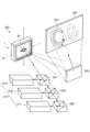
次に、光スキャナー1の製造方法について、図11〜図13を参照して説明する。図11は、光スキャナーの製造方法のフローチャートである。図12は、光スキャナーの製造工程における構成部材の位置関係を示す断面図である。図13は、支持部材と可動部との接続状態を示す説明図である。 Next, a method for manufacturing the optical scanner 1 will be described with reference to FIGS. FIG. 11 is a flowchart of a method for manufacturing an optical scanner. FIG. 12 is a cross-sectional view showing the positional relationship of the constituent members in the manufacturing process of the optical scanner. FIG. 13 is an explanatory diagram illustrating a connection state between the support member and the movable portion.
まず、図11に示す第1固定工程(S101)を実施する。
図12(a)に示すように、振動基板11を保持部材(図示省略)などにより保持し、基台12の基板保持部122と向き合わせる。
そして、図12(b)に示すように、振動基板11の固定部13を、基台12の基板保持部122に配置する。そして、接着剤または陽極接合等の各種接合方法を用いて、固定部13を基板保持部122に固定する。これにより、振動基板11は基台12に固定される。なお、このときの振動基板11は、光反射部材20及び支持部材23が取り付けられていない状態の振動基板11である。
First, the first fixing step (S101) shown in FIG. 11 is performed.
As shown in FIG. 12A, the
Then, as shown in FIG. 12B, the fixing
次に、図11に示す第2固定工程(S102)を実施する。
図13(a)、及び図13(b)に示すように、4つの可動部201,202,203,204に、光反射部材20が固定された支持部材23を接着する。図13(a)は、図1の裏面から見た図である。また、図13(b)は、図13(a)のX1軸の断面図である。
Next, the second fixing step (S102) shown in FIG. 11 is performed.
As shown in FIGS. 13A and 13B, the
ここで、図12および図13において、振動基板11に永久磁石821(811,831,841)を固定しているとして図示したが、これに限るものではなく、第1固定工程(S101)、または、第2固定工程(S102)の後に永久磁石821(811,831,841)を固定するとしてもよい。
12 and 13, the permanent magnet 821 (811, 831, 841) is illustrated as being fixed to the
このようにして、光反射部材を備えた光スキャナーを製造することが出来る。基台と固定部を固定することにより、可動梁、及び、駆動梁には、応力による歪が生じるが、可動部が複数設けられており、基台と固定部の固定工程の後に、支持部材を可動部に固定することによって、応力による歪を緩和しながら、光反射部材を備えた光スキャナーを得ることが出来る。 Thus, the optical scanner provided with the light reflection member can be manufactured. By fixing the base and the fixed part, the movable beam and the driving beam are distorted by stress. However, a plurality of movable parts are provided, and after the fixing process of the base and the fixed part, the support member By fixing the to the movable part, it is possible to obtain an optical scanner including a light reflecting member while alleviating distortion due to stress.
<第2実施形態>
第2実施形態の光スキャナー、および光スキャナーの製造方法について、図14〜図16を参照して説明する。
本実施形態の光スキャナーの製造方法は、上述した振動基板11を含むミラーチップ10を用いて、光スキャナー1を製造する方法である。このため同様の構成については、同一の符号を付与し、構成の説明を省略する。
図14は、ミラーチップの構成を示す平面図である。図15は、光スキャナーの製造工程を示すフローチャートである。図16は、光スキャナーの製造工程における構成部材の位置関係を示す断面図である。
Second Embodiment
The optical scanner of 2nd Embodiment and the manufacturing method of an optical scanner are demonstrated with reference to FIGS.
The manufacturing method of the optical scanner of this embodiment is a method of manufacturing the optical scanner 1 using the
FIG. 14 is a plan view showing the configuration of the mirror chip. FIG. 15 is a flowchart showing a manufacturing process of the optical scanner. FIG. 16 is a cross-sectional view showing the positional relationship of components in the manufacturing process of the optical scanner.
図15に示すフローチャートにおいて、第1固定工程(S201)は、シリコン基板上に形成されたミラーチップ10を、基台12へ貼り付ける工程である。次に、分離工程(S202)は、基台12に固定されたミラーチップ10から、支持部3を分離する工程である。最後に、第2固定工程(S203)は、4つの可動部201,202,203,204と支持部材23とを接着する工程である。
In the flowchart shown in FIG. 15, the first fixing step (S <b> 201) is a step of attaching the
図14に示すように、ミラーチップ10は、支持部3と、分離部14と、振動基板11とを備えている。
As shown in FIG. 14, the
支持部3は、振動基板11を取り囲んで形成されている。すなわち、支持部3は、可動部201,202,203,204、可動梁42,52,62,72、変位部41,51,61,71、駆動梁43,53,63,73、および固定部13を取り囲んで形成されている。
そして、支持部3は、分離部14により固定部13と連結されている。ミラーチップ10において、分離部14は支持部3と固定部13との間を部分的に連結している。すなわち、分離部14は、支持部3や固定部13に対して構造的な強度が弱くなるように形成されている。このため、分離部14において支持部3と固定部13とを確実に分離することが可能である。分離部14は、支持部3や固定部13に対して構造的な強度が弱くなるように構成されていればよく、上記の構成に限定されない。例えば、支持部3や固定部13の厚みによりも分離部14の厚みが小さくなるように形成してもよい。
なお、支持部3は、固定部13の外側に形成され、分離部14を介して固定部13の間を接続していればよく、上記の形に限定されるものではない。
The
The
In addition, the
まず、図15に示す第1固定工程(S201)を実施する。
図16(a)に示すように、ミラーチップ10を保持部材(図示省略)などにより保持し、基台12の基板保持部122と向き合わせる。
そして、図16(b)に示すように、振動基板11の固定部13を、基台12の基板保持部122に配置する。そして、接着剤または陽極接合等の各種接合方法を用いて、固定部13を基板保持部122に固定する。これにより、振動基板11は基台12に固定される。なお、このときのミラーチップ10(振動基板11)は、光反射部材20及び支持部材23が取り付けられていない状態のミラーチップ10(振動基板11)である。
First, the first fixing step (S201) shown in FIG. 15 is performed.
As shown in FIG. 16A, the
Then, as illustrated in FIG. 16B, the fixing
次に、図15に示す分離工程(S202)を実施する。
図16(c)に示すように、保持治具91および分離治具92を矢印の方向に移動させ、保持治具91により固定部13を押し付け、分離治具92により支持部3および分離部14を押し付ける。ここで、分離部14は、保持治具91または分離治具92により押し付けられていてもよく、いずれにも押し付けられないとしてもよく、適宜選択することができる。また、保持治具91および分離治具92を矢印の方向に移動させるとしたが、これに限るものではなく、固定部13、つまり基台12を矢印の方向と逆の方向に移動させるとしてもよく、または保持治具91および分離治具92を矢印の方向に移動させるとともに、基台12を矢印の方向と逆の方向に移動させるとしてもよい。
引き続き、図16(d)に示すように、分離治具92を矢印の方向に移動させ、分離部14を破壊させて折り取ることで、基台12に固定されたミラーチップ10から、支持部3を分離する。これにより、固定部13が基台12によって支持された光スキャナー1を得る(図2参照)。
Next, the separation step (S202) shown in FIG. 15 is performed.
As shown in FIG. 16C, the holding
Subsequently, as shown in FIG. 16D, the
引き続き、図15に示す第2固定工程(S203)を実施する。
第2固定工程(S203)では、上述した第2固定工程(S102)と同様に、4つの可動部201,202,203,204と、光反射部材20が固定された支持部材23とを接着する。
Subsequently, the second fixing step (S203) shown in FIG. 15 is performed.
In the second fixing step (S203), as in the second fixing step (S102) described above, the four
ここで、図16において、振動基板11に永久磁石821(811,831,841)を固定しているとして図示したが、これに限るものではなく、第1固定工程(S201)、または、分離工程(S202)、または、第2固定工程(S203)の後に永久磁石821(811,831,841)を固定するとしてもよい。
Here, in FIG. 16, the permanent magnet 821 (811, 831, 841) is illustrated as being fixed to the
本実施形態の製造方法によれば、ミラーチップ10は、固定部13が駆動梁43,53,63,73だけでなく、支持部3および分離部14により固定部が連結されて振動基板11が連結されているので、固定部13が駆動梁43,53,63,73だけに連結された振動基板11の場合と比べて剛性を高くすることができる。そのため、ミラーチップ10を保持して、振動基板11を基台12の基板保持部122に配置して、振動基板11と基台12とを接合させる際などにおいて、振動基板11を破損させることなく、上述のように、保持して、配置して、接合されることが可能となる。
さらに、第1固定工程の固定部13と基台12の固定により生じる歪は、複数の可動部201,202,203,204が設けられていることにより、緩和され、分離工程により、支持部3を取り除いた後に、可動部201,202,203,204と支持部材23を固着する第2固定工程を実施することによって、歪の影響を小さくしながら、光スキャナーを得ることが出来る。
According to the manufacturing method of this embodiment, in the
Furthermore, the distortion caused by the fixing of the fixing
また、支持部3を分離部14において折り取るので、支持部3が振動基板11を支持したままの構成に比べて、XY平面視にて小型化させた光スキャナー1を得ることができる。さらには、第1実施形態と同様に、消費電力化を実現する光スキャナー1を得ることができる。
Further, since the
<第3実施形態>
第3実施形態の画像形成装置について、図17を参照して説明する。
第3実施形態の画像形成装置は、第1実施形態の光スキャナーを備えている。また、かかる光スキャナーは、第1実施形態の構成と同様な構成を備えるか、または、第2実施形態で説明した製造方法と同様な製造方法を用いて製造されている。このため、同様の構成および製造方法については、同一の符号を付与し、構成および製造方法などの説明を省略する。
<Third Embodiment>
An image forming apparatus according to a third embodiment will be described with reference to FIG.
The image forming apparatus according to the third embodiment includes the optical scanner according to the first embodiment. The optical scanner has the same configuration as that of the first embodiment, or is manufactured using a manufacturing method similar to the manufacturing method described in the second embodiment. For this reason, about the same structure and manufacturing method, the same code | symbol is provided and description of a structure, a manufacturing method, etc. is abbreviate | omitted.
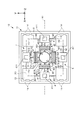
以上説明したような光スキャナー1は、例えば、プロジェクター、レーザープリンター、イメージング用ディスプレイ、バーコードリーダー、走査型共焦点顕微鏡などの画像形成装置に好適に適用することができる。図17は、本発明の画像形成装置の概要を示す模式図である。図17には、画像形成装置としてのプロジェクター300が示されている。ここでは、スクリーン380の長手方向を「横方向」といい、長手方向に直角な方向を「縦方向」という。プロジェクター300は、レーザーなどの光を出射する光源装置310と、複数のダイクロイックミラー320と、光スキャナー1とを有している。
The optical scanner 1 as described above can be suitably applied to an image forming apparatus such as a projector, a laser printer, an imaging display, a barcode reader, and a scanning confocal microscope. FIG. 17 is a schematic diagram showing an outline of the image forming apparatus of the present invention. FIG. 17 shows a
光源装置310は、赤色光を出射する赤色光源装置311と、青色光を出射する青色光源装置312と、緑色光を出射する緑色光源装置313とを備えている。各ダイクロイックミラー320は、赤色光源装置311、青色光源装置312、緑色光源装置313のそれぞれから出射された光を合成する光学素子である。このようなプロジェクター300は、図示しないホストコンピューターからの画像情報に基づいて、光源装置310から出射された光をダイクロイックミラー320で合成し、この合成された光が光スキャナー1によって2次元走査され、固定ミラー350を介してスクリーン380上にカラー画像を形成するよう構成されている。
The
2次元走査の際、光スキャナー1の光反射部22が、Y軸方向の軸まわりに回動し、光反射部22で反射した光がスクリーン380の横方向に走査(主走査)される。一方、光スキャナー1の光反射部22が、X軸方向の軸まわりに回動し、光反射部22で反射した光がスクリーン380の縦方向に走査(副走査)される。光スキャナー1による光の走査は、いわゆるラスタースキャンによって行ってもよいし、いわゆるベクタースキャンによって行ってもよい。特に、光スキャナー1においては、その構成上、ベクタースキャンに適しているため、ベクタースキャンによって光を走査するのが好ましい。
At the time of two-dimensional scanning, the
光スキャナー1にとって好ましいベクタースキャンとは、光源装置310から出射された光を、スクリーン380に対し、該スクリーン380上の異なる2点を結ぶ線分を順次形成するように走査する手法である。すなわち、微少な直線を集合させることにより、スクリーン380に所望の画像を形成する手法である。光スキャナー1では、光反射部22を、Y軸方向の軸まわりおよびX軸方向の軸まわりに、不規則に且つ連続的に変位させることが可能であるため、ベクタースキャンに特に適している。
The vector scan preferable for the optical scanner 1 is a method of scanning the light emitted from the
具体的に説明すれば、図17に示すような文字(aおよびb)をベクタースキャンにて描画する場合には、光源装置310から出射された光をそれぞれの文字を書くように走査する。この際、光スキャナー1が有する光反射部22のX軸方向の軸まわりの姿勢(回動)とY軸方向の軸まわりの姿勢(回動)とをそれぞれ制御して、走査軌跡330に沿って不規則に光を走査することができ、aおよびbの文字を一筆書きのように描画することができる。このようなベクタースキャンによれば、ラスタースキャンのように、スクリーン380の全面に光を走査させなくてよいため、効率的に画像を描画することができる。なお、図17では、ダイクロイックミラー320で合成された光を光スキャナー1によって2次元的に走査した後、その光を固定ミラー350で反射させてからスクリーン380に画像を形成するように構成されているが、固定ミラー350を省略し、光スキャナー1によって2次元的に走査された光を直接スクリーン380に照射してもよい。
More specifically, when characters (a and b) as shown in FIG. 17 are drawn by vector scanning, the light emitted from the
本実施形態によれば、上述した実施形態で説明した光スキャナー1と同様の効果を奏することが可能な画像形成装置としてのプロジェクター300を提供することができる。
According to the present embodiment, it is possible to provide a
なお、上記課題の少なくとも一部を解決できる範囲での変形、改良などは前述の実施形態に含まれるものである。 In addition, the deformation | transformation in the range which can solve at least one part of the said subject, improvement, etc. are contained in above-mentioned embodiment.
たとえば、図14に示した分離部14の配置、形状、および数量などは、振動基板11の支持部3と固定部13との連結、および分離工程(S202)での支持部3の分離を考慮して、適宜決定することができる。
For example, the arrangement, shape, quantity, and the like of the
また、内枠部411のXY平面視形状は、図1、図3、及び図14などに示した矩形に限定されず、例えば、三角形や正方形や五角形以上の多角形、または円形または楕円形であってもよく、適宜決定することができる。
Further, the XY plan view shape of the
また、永久磁石811,821,831,841のXY平面視形状としては、図1および図3で矩形と図示したが、特に限定されず、例えば、三角形や正方形や五角形以上の多角形、円形、楕円形であってもよい。
Further, the XY plan view shape of the
さらに、コイル固定部、変位手段、応力緩和部、振動基板、および可動板の構成および形状、ならびに振動基板を図示上下に反転して光反射部材を取り付けるなどは、前述の実施形態を限定するものではなく、適宜変更することが可能である。 Further, the configurations and shapes of the coil fixing portion, the displacement means, the stress relaxation portion, the vibration substrate, and the movable plate, and the light reflection member attached by inverting the vibration substrate up and down in the drawing are limited to the above-described embodiments. Instead, it can be changed as appropriate.
以上、添付図面を参照しながら好適な実施形態について説明したが、好適な実施形態は、前記実施形態に限らない。実施形態は、要旨を逸脱しない範囲内において種々変更を加え得ることは勿論であり、以下のように実施することもできる。 As mentioned above, although preferred embodiment was described referring an accompanying drawing, suitable embodiment is not restricted to the said embodiment. The embodiment can of course be modified in various ways without departing from the scope, and can also be implemented as follows.
(変形例1)前記実施形態においては、光反射部材20は、支持部材23を介して可動部201、202、203、204に固定されている。しかし、光反射部材が支持部材を介して可動部に支持されることは必須ではない。光反射部材は、直接可動部に支持される構成であってもよい。
(Modification 1) In the above embodiment, the
1…光スキャナー、3…支持部、4,5,6,7…連結部、8…変位手段、11…振動基板、12…基台、13…固定部、14…分離部、20…光反射部材、21…面、22…光反射部、23…支持部材、41,51,61,71…変位部、42,52,62,72…可動梁、43,53,63,73…駆動梁、81…第1の変位手段、82…第2の変位手段、83…第3の変位手段、84…第4の変位手段、85…コイル固定部、91…保持治具、92…分離治具、121…基部、122…基板保持部、201,202,203,204…可動部、261,262,263,264,271,272,273,274,281,282,283,284…凹部、300…プロジェクター、310…光源装置、311…赤色光源装置、312…青色光源装置、313…緑色光源装置、320…ダイクロイックミラー、330…走査軌跡、350…固定ミラー、380…スクリーン、411…内枠部、421,521,621,721…屈曲部、422,522,622,722…可動部側可動梁、423,523,623,723…変位部側可動梁、810,820,830,840…駆動部、811,821,831,841…永久磁石、812,822,832,842…コイル、813,823,833,843…電源、851…突出部、4211,4212,6211,6212…変形部、4213,5213,6213,7213…非変形部、4214,4215,5214,5215,6214,6215,7214,7215…接続部、X1,X2,X3,Y1,Y2,Y3,Y4…回動中心軸。
DESCRIPTION OF SYMBOLS 1 ... Optical scanner, 3 ... Support part, 4, 5, 6, 7 ... Connection part, 8 ... Displacement means, 11 ... Vibration board, 12 ... Base, 13 ... Fixed part, 14 ... Separation part, 20 ... Light reflection Member, 21 ... surface, 22 ... light reflection part, 23 ... support member, 41, 51, 61, 71 ... displacement part, 42, 52, 62, 72 ... movable beam, 43, 53, 63, 73 ... drive beam, 81: First displacement means, 82: Second displacement means, 83: Third displacement means, 84: Fourth displacement means, 85: Coil fixing portion, 91: Holding jig, 92: Separation jig, 121: Base, 122: Substrate holder, 201, 202, 203, 204 ... Movable part, 261, 262, 263, 264, 271, 272, 273, 274, 281, 282, 283, 284 ... Recess, 300 ...
Claims (7)
前記光反射部材を支持する4つの可動部と、
前記4つの可動部のそれぞれの可動部にそれぞれの一端が接続されており、前記光反射面の面方向に略平行に延在し、前記光反射面の平面視にて前記光反射部材の周方向に沿って90度間隔で設けられた4つの可動梁と、
前記可動梁の前記可動部に接続された前記一端の他の一端に連結された変位部と、
前記変位部に固定された永久磁石と、
前記可動梁の延長方向に前記変位部から隔てて配置され、前記永久磁石と協働して前記変位部を駆動する駆動部と、
前記変位部に一端が接続されており、前記可動梁に略直交するとともに前記光反射面の面方向に略平行に延在し、前記変位部を支持する駆動梁と、
前記駆動梁の前記変位部に接続された前記一端の他の一端が連結された固定部と、
前記固定部が固定された基台と、を備え、
前記可動梁は、前記光反射面の前記面方向と略垂直な方向に前記可動梁を屈曲変形させる屈曲部を有し、
前記光反射部材と前記4つの可動部とが接着剤を介して固着されていることを特徴とする光スキャナー。 A light reflecting member having a light reflecting surface;
Four movable parts that support the light reflecting member;
One end of each of the four movable parts is connected to the movable part, extends substantially parallel to the surface direction of the light reflecting surface, and surrounds the light reflecting member in a plan view of the light reflecting surface. Four movable beams provided at intervals of 90 degrees along the direction;
A displacement part coupled to the other end of the one end connected to the movable part of the movable beam;
A permanent magnet fixed to the displacement part;
A drive unit that is arranged in the extending direction of the movable beam and spaced from the displacement unit, and that drives the displacement unit in cooperation with the permanent magnet;
One end is connected to the displacement portion, the drive beam is substantially orthogonal to the movable beam and extends substantially parallel to the surface direction of the light reflecting surface, and supports the displacement portion;
A fixed part connected to the other end of the one end connected to the displacement part of the driving beam;
A base on which the fixing part is fixed,
The movable beam has a bent portion that bends and deforms the movable beam in a direction substantially perpendicular to the surface direction of the light reflecting surface;
The light scanner, wherein the light reflecting member and the four movable parts are fixed with an adhesive.
前記光反射部材は、前記可動梁と接触しない状態で、前記可動部に固着されていることを特徴とする光スキャナー。 The optical scanner according to claim 1.
The light scanner, wherein the light reflecting member is fixed to the movable portion without contacting the movable beam.
支持部材をさらに備え、
前記可動部は、前記支持部材を介して前記光反射部材を支持し、
前記支持部材は、前記可動梁と接触しない状態で、前記光反射部材及び前記可動部と固着されていることを特徴とする光スキャナー。 The optical scanner according to claim 1.
A support member;
The movable part supports the light reflecting member via the support member,
The optical scanner according to claim 1, wherein the support member is fixed to the light reflecting member and the movable portion in a state where the support member is not in contact with the movable beam.
前記支持部材は、前記可動部の形状と係合する形状を有する係合部を備えることを特徴とする光スキャナー。 The optical scanner according to claim 3.
The optical scanner according to claim 1, wherein the support member includes an engaging portion having a shape that engages with the shape of the movable portion.
前記光反射部材を支持する4つの可動部と、
前記4つの可動部のそれぞれの可動部にそれぞれの一端が接続されており、前記光反射面の面方向に略平行に延在し、前記光反射面の平面視にて前記光反射部材の周方向に沿って90度間隔で設けられた4つの可動梁と、
前記可動梁の前記可動部に接続された前記一端の他の一端に連結された変位部と、
前記変位部に固定された永久磁石と、
前記可動梁の延長方向に前記変位部から隔てて配置され、前記永久磁石と協働して前記変位部を駆動する駆動部と、
前記変位部に一端が接続されており、前記可動梁に略直交するとともに前記光反射面の面方向に略平行に延在し、前記変位部を支持する駆動梁と、
前記駆動梁の前記変位部に接続された前記一端の他の一端が連結された固定部と、
前記固定部が固定された基台と、を備え、前記可動梁は、前記光反射面の前記面方向と略垂直な方向に前記可動梁を屈曲変形させる屈曲部を有し、前記光反射部材と前記可動部とが接着剤を介して固着されている光スキャナーの製造方法であって、
前記可動部、前記可動梁、前記変位部、前記永久磁石、前記駆動梁、および前記固定部を備える振動基板を製造する工程と、
前記固定部を前記基台に固定する第1固定工程と、
前記光反射部材を前記可動部に固定する第2固定工程と、を有し、
前記第1固定工程を実施した後に、前記第2固定工程を実施することを特徴とする光スキャナーの製造方法。 A light reflecting member having a light reflecting surface;
Four movable parts that support the light reflecting member;
One end of each of the four movable parts is connected to the movable part, extends substantially parallel to the surface direction of the light reflecting surface, and surrounds the light reflecting member in a plan view of the light reflecting surface. Four movable beams provided at intervals of 90 degrees along the direction;
A displacement part coupled to the other end of the one end connected to the movable part of the movable beam;
A permanent magnet fixed to the displacement part;
A drive unit that is arranged in the extending direction of the movable beam and spaced from the displacement unit, and that drives the displacement unit in cooperation with the permanent magnet;
One end is connected to the displacement portion, the drive beam is substantially orthogonal to the movable beam and extends substantially parallel to the surface direction of the light reflecting surface, and supports the displacement portion;
A fixed part connected to the other end of the one end connected to the displacement part of the driving beam;
A base on which the fixed portion is fixed, and the movable beam has a bent portion that bends and deforms the movable beam in a direction substantially perpendicular to the surface direction of the light reflecting surface, and the light reflecting member And the movable part is a method of manufacturing an optical scanner fixed through an adhesive,
Producing a vibration substrate comprising the movable part, the movable beam, the displacement part, the permanent magnet, the drive beam, and the fixed part;
A first fixing step of fixing the fixing portion to the base;
A second fixing step of fixing the light reflecting member to the movable part,
An optical scanner manufacturing method, wherein the second fixing step is performed after the first fixing step.
前記振動基板は、前記光反射部材、前記可動部、前記可動梁、前記変位部、前記駆動梁、および前記固定部を取り囲んで形成される支持部と、
前記固定部と前記支持部とを連結する分離部と、をさらに備え、
前記第1固定工程と前記第2固定工程との間に、
前記分離部において前記固定部と前記支持部とを分離する分離工程をさらに有することを特徴とする光スキャナーの製造方法。 In the manufacturing method of the optical scanner of Claim 5,
The vibration substrate includes a support portion formed to surround the light reflecting member, the movable portion, the movable beam, the displacement portion, the driving beam, and the fixed portion,
A separation part that connects the fixing part and the support part;
Between the first fixing step and the second fixing step,
The method of manufacturing an optical scanner, further comprising a separation step of separating the fixing portion and the support portion in the separation portion.
前記光スキャナーは、
光反射面を有する光反射部材と、
前記光反射部材を支持する4つの可動部と、
前記4つの可動部のそれぞれの可動部にそれぞれの一端が接続されており、前記光反射面の面方向に略平行に延在し、前記光反射面の平面視にて前記光反射部材の周方向に沿って90度間隔で設けられた4つの可動梁と、
前記可動梁の前記可動部に接続された前記一端の他の一端に連結された変位部と、
前記変位部に固定された永久磁石と、
前記可動梁の延長方向に前記変位部から隔てて配置され、前記永久磁石と協働して前記変位部を駆動する駆動部と、
前記変位部に一端が接続されており、前記可動梁に略直交するとともに交差して前記光反射面の面方向に略平行に延在し、前記変位部を支持する駆動梁と、
前記駆動梁の前記変位部に接続された前記一端の他の一端が連結された固定部と、
前記固定部が固定された基台と、を備え、
前記可動梁は、前記光反射面の前記面方向と略垂直な方向に前記可動梁を屈曲変形させる屈曲部を有し、
前記光反射部材と前記可動部とが接着剤を介して固着されていることを特徴とする画像形成装置。 A light source, and an optical scanner that scans light from the light source,
The optical scanner is
A light reflecting member having a light reflecting surface;
Four movable parts that support the light reflecting member;
One end of each of the four movable parts is connected to the movable part, extends substantially parallel to the surface direction of the light reflecting surface, and surrounds the light reflecting member in a plan view of the light reflecting surface. Four movable beams provided at intervals of 90 degrees along the direction;
A displacement part coupled to the other end of the one end connected to the movable part of the movable beam;
A permanent magnet fixed to the displacement part;
A drive unit that is arranged in the extending direction of the movable beam and spaced from the displacement unit, and that drives the displacement unit in cooperation with the permanent magnet;
One end is connected to the displacement portion, the drive beam is substantially orthogonal to the movable beam and intersects and extends substantially parallel to the surface direction of the light reflecting surface, and supports the displacement portion;
A fixed part connected to the other end of the one end connected to the displacement part of the driving beam;
A base on which the fixing part is fixed,
The movable beam has a bent portion that bends and deforms the movable beam in a direction substantially perpendicular to the surface direction of the light reflecting surface;
The image forming apparatus, wherein the light reflecting member and the movable portion are fixed with an adhesive.
Priority Applications (1)
| Application Number | Priority Date | Filing Date | Title |
|---|---|---|---|
| JP2010281340A JP2012128307A (en) | 2010-12-17 | 2010-12-17 | Optical scanner, manufacturing method of optical scanner and image forming device |
Applications Claiming Priority (1)
| Application Number | Priority Date | Filing Date | Title |
|---|---|---|---|
| JP2010281340A JP2012128307A (en) | 2010-12-17 | 2010-12-17 | Optical scanner, manufacturing method of optical scanner and image forming device |
Publications (1)
| Publication Number | Publication Date |
|---|---|
| JP2012128307A true JP2012128307A (en) | 2012-07-05 |
Family
ID=46645364
Family Applications (1)
| Application Number | Title | Priority Date | Filing Date |
|---|---|---|---|
| JP2010281340A Withdrawn JP2012128307A (en) | 2010-12-17 | 2010-12-17 | Optical scanner, manufacturing method of optical scanner and image forming device |
Country Status (1)
| Country | Link |
|---|---|
| JP (1) | JP2012128307A (en) |
Cited By (2)
| Publication number | Priority date | Publication date | Assignee | Title |
|---|---|---|---|---|
| US9182593B2 (en) | 2012-05-11 | 2015-11-10 | Seiko Epson Corporation | Optical device, optical scanner, and image display device |
| US9563054B2 (en) | 2012-05-11 | 2017-02-07 | Seiko Epson Corporation | Optical device, optical scanner, and image display device |
-
2010
- 2010-12-17 JP JP2010281340A patent/JP2012128307A/en not_active Withdrawn
Cited By (2)
| Publication number | Priority date | Publication date | Assignee | Title |
|---|---|---|---|---|
| US9182593B2 (en) | 2012-05-11 | 2015-11-10 | Seiko Epson Corporation | Optical device, optical scanner, and image display device |
| US9563054B2 (en) | 2012-05-11 | 2017-02-07 | Seiko Epson Corporation | Optical device, optical scanner, and image display device |
Similar Documents
| Publication | Publication Date | Title |
|---|---|---|
| JP5577742B2 (en) | Optical scanner and image forming apparatus | |
| JP5659672B2 (en) | Optical scanner, mirror chip, optical scanner manufacturing method, and image forming apparatus | |
| JP5659642B2 (en) | Optical scanner, optical scanner manufacturing method, and image forming apparatus | |
| JP5598296B2 (en) | Actuator, optical scanner and image forming apparatus | |
| JP5333286B2 (en) | Optical scanner and image forming apparatus | |
| JP5447272B2 (en) | Optical scanner and image forming apparatus | |
| JP2012108165A (en) | Actuator, optical scanner and image formation device | |
| JP2012123116A (en) | Actuator, optical scanner and image forming device | |
| JP4984987B2 (en) | Actuator, optical scanner and image forming apparatus | |
| JP2012108164A (en) | Actuator, optical scanner and image formation device | |
| JP5447283B2 (en) | Optical scanner and image forming apparatus | |
| JP2012128307A (en) | Optical scanner, manufacturing method of optical scanner and image forming device | |
| JP2012123117A (en) | Actuator, optical scanner and image forming device | |
| JP5923933B2 (en) | Mirror device, optical scanner and image forming apparatus | |
| JP5867547B2 (en) | Optical scanner and image forming apparatus | |
| JP5803586B2 (en) | Mirror device, optical scanner and image forming apparatus | |
| JP5294033B2 (en) | Optical scanning apparatus and image forming apparatus | |
| JP5045611B2 (en) | Actuator, optical scanner and image forming apparatus | |
| JP2009093107A (en) | Actuator, optical scanner, and image forming device | |
| JP4984988B2 (en) | Actuator, optical scanner and image forming apparatus | |
| JP2014016443A (en) | Optical scanner, mirror chip, method for manufacturing optical scanner, and image forming apparatus | |
| JP2013190724A (en) | Optical scanner and image forming device | |
| JP2011100074A (en) | Optical device, optical scanner and image forming apparatus |
Legal Events
| Date | Code | Title | Description |
|---|---|---|---|
| A300 | Withdrawal of application because of no request for examination |
Free format text: JAPANESE INTERMEDIATE CODE: A300 Effective date: 20140304 |