JP2012125920A - Fastener-driving machine and method for driving the same - Google Patents
Fastener-driving machine and method for driving the same Download PDFInfo
- Publication number
- JP2012125920A JP2012125920A JP2011273680A JP2011273680A JP2012125920A JP 2012125920 A JP2012125920 A JP 2012125920A JP 2011273680 A JP2011273680 A JP 2011273680A JP 2011273680 A JP2011273680 A JP 2011273680A JP 2012125920 A JP2012125920 A JP 2012125920A
- Authority
- JP
- Japan
- Prior art keywords
- combustion chamber
- driving
- volume
- driving machine
- adjusting
- Prior art date
- Legal status (The legal status is an assumption and is not a legal conclusion. Google has not performed a legal analysis and makes no representation as to the accuracy of the status listed.)
- Granted
Links
Images
Classifications
-
- B—PERFORMING OPERATIONS; TRANSPORTING
- B25—HAND TOOLS; PORTABLE POWER-DRIVEN TOOLS; MANIPULATORS
- B25C—HAND-HELD NAILING OR STAPLING TOOLS; MANUALLY OPERATED PORTABLE STAPLING TOOLS
- B25C1/00—Hand-held nailing tools; Nail feeding devices
- B25C1/08—Hand-held nailing tools; Nail feeding devices operated by combustion pressure
-
- B—PERFORMING OPERATIONS; TRANSPORTING
- B25—HAND TOOLS; PORTABLE POWER-DRIVEN TOOLS; MANIPULATORS
- B25C—HAND-HELD NAILING OR STAPLING TOOLS; MANUALLY OPERATED PORTABLE STAPLING TOOLS
- B25C1/00—Hand-held nailing tools; Nail feeding devices
-
- B—PERFORMING OPERATIONS; TRANSPORTING
- B25—HAND TOOLS; PORTABLE POWER-DRIVEN TOOLS; MANIPULATORS
- B25C—HAND-HELD NAILING OR STAPLING TOOLS; MANUALLY OPERATED PORTABLE STAPLING TOOLS
- B25C1/00—Hand-held nailing tools; Nail feeding devices
- B25C1/06—Hand-held nailing tools; Nail feeding devices operated by electric power
Abstract
Description
本発明は、容積可変の燃焼室内で可燃性の混合ガス(燃料と酸素または空気とが混合されたガス)に点火することにより瞬時に直線移動させうるピストンを備える、被打ち込み材にファスナー(ボルト、釘、鋲等)を打ち込むための打ち込み機に関する。また、本発明は、この打ち込み機の駆動方法にも関する。 The present invention includes a piston (bolt) for a material to be driven, which includes a piston that can be moved linearly instantaneously by igniting a combustible mixed gas (a gas in which fuel and oxygen or air are mixed) in a combustion chamber having a variable volume. , Nails, scissors, etc.). The present invention also relates to a driving method of the driving machine.
特許文献1は、混合ガスを取り込む燃焼室を備え、混合ガスの燃焼時に発生する力によって駆動される手動式の打ち込み機を開示している。ここで、燃焼室の容積は、燃焼室の正面側の壁体が軸方向に移動することにより変化させることができ、このことによって、燃焼室内に存在する混合ガスの量を少なくし又は多くする方向に調整することができるようになっている。また、特許文献2は、ガスの燃焼時に発生する力によって駆動される、開口面積が可変に調整される開口を有する壁体によって隔てられた2つの分室を有する打ち込み機を開示している。
Patent Document 1 discloses a manual driving machine that includes a combustion chamber that takes in a mixed gas and is driven by a force generated when the mixed gas is burned. Here, the volume of the combustion chamber can be changed by the axial movement of the front wall of the combustion chamber, thereby reducing or increasing the amount of the mixed gas existing in the combustion chamber. It can be adjusted in the direction.
本発明の課題は、請求項1の前提部に記載した打ち込み機の操作性および/またはエネルギー効率を高めることである。 An object of the present invention is to improve the operability and / or energy efficiency of a driving machine described in the premise of claim 1.
上記の課題は、容積が変化しうる燃焼室内で可燃性の混合ガスに点火することを通じて、瞬時に直線的に移動させうるピストンを備え、ボルト、釘等のファスナーを被打ち込み材に打ち込むための打ち込み機において、前記燃焼室の容積を調整する装置およびガスの送給量を計量する計量弁と制御的に接続されたコントローラを備えていることを特徴とする打ち込み機によって解決される。本発明の打ち込み機は、持ち運び可能で、ガスの燃焼に伴う力で駆動されるものである。ファスナーを打ち込むため、例えばカートリッジ式のガスタンクから供給されるガスは、燃焼室において酸素または空気と混合され、可燃性の混合ガスとなる。可燃性のガスが点火されると、ガスは急激に膨張し、ピストンを推進する。本発明の打ち込み機は、燃焼室の容積を調整する装置と計量弁との組み合わせにより、広範なエネルギー領域に対応しつつ、エネルギーの効率的な利用を図ることができる。その結果、稼働時(特にファスナーの打ち込み時)に打ち込み機に加わる負荷は、最小のエネルギーに対応するもので済み、大幅に軽減される。このため、打ち込み機の耐用年数も延びる。 In order to drive a fastener such as a bolt or a nail into a material to be driven, a piston that can be moved instantaneously and linearly by igniting a combustible mixed gas in a combustion chamber whose volume can change. The driving machine is solved by a driving machine characterized by comprising a controller for controlling the volume of the combustion chamber and a metering valve for metering the amount of gas delivered, in control. The driving machine of the present invention is portable and is driven by a force accompanying gas combustion. In order to drive the fastener, for example, gas supplied from a cartridge-type gas tank is mixed with oxygen or air in the combustion chamber to become a combustible mixed gas. When the combustible gas is ignited, the gas expands rapidly and propels the piston. The driving machine according to the present invention can efficiently use energy while accommodating a wide energy range by combining a device for adjusting the volume of a combustion chamber and a metering valve. As a result, the load applied to the driving machine during operation (especially when the fastener is driven) only needs to correspond to the minimum energy and is greatly reduced. For this reason, the service life of the driving machine is extended.
本発明の好ましい態様によれば、燃焼室の容積を調整する装置は、モータ、特に電動機を備えている。燃焼室の容積を調整するためには、ステッピングモータを用いるのが好ましい。このモータは、コントローラによって制御される。 According to a preferred aspect of the invention, the device for adjusting the volume of the combustion chamber comprises a motor, in particular an electric motor. In order to adjust the volume of the combustion chamber, it is preferable to use a stepping motor. This motor is controlled by a controller.
本発明の他の好ましい態様によれば、モータは、ギヤボックスを介して、燃焼室の移動可能な壁体と連結されている。このギヤボックスは、燃焼室の圧力によって負荷を受けた際には、自ら停止して、壁体をそのときの位置に止まらせるように働くのが好ましい。さらに、ギヤボックスは、燃焼室の圧力がモータの作動に影響を及ぼさないように設計するのが好ましい。一方、モータは、打ち込み機内に緩衝部材とともに収容するのが好ましい。 According to another preferred aspect of the present invention, the motor is connected to the movable wall of the combustion chamber via a gear box. The gearbox preferably works so as to stop itself when it receives a load due to the pressure in the combustion chamber and to stop the wall body at that position. Furthermore, the gearbox is preferably designed so that the pressure in the combustion chamber does not affect the operation of the motor. On the other hand, the motor is preferably housed together with the buffer member in the driving machine.
本発明のさらに他の好ましい態様によれば、コントローラは、打ち込みに係るエネルギーを調整する調整操作器および/または前記エネルギーに関する情報を表示する表示装置と接続されている。作業員は、このような調整操作器の助けを借りて、打ち込みに係る目標エネルギーを容易に設定することができる。また、表示装置の助けを借りて、目標エネルギーを容易に表示することができ、さらに、打ち込みに係る最大・最小の出力可能エネルギーも表示することができる。したがって、打ち込み機の操作は、大幅に楽になる。 According to still another preferred aspect of the present invention, the controller is connected to an adjustment controller for adjusting energy related to driving and / or a display device for displaying information related to the energy. The operator can easily set the target energy for driving with the help of such an adjusting device. In addition, the target energy can be easily displayed with the help of the display device, and the maximum and minimum output possible energy related to driving can also be displayed. Therefore, the operation of the driving machine is greatly facilitated.
上記の課題は、すでに説明した本発明の打ち込み機に加えて、またはこれに代えて、燃焼室の容積の調整、および燃焼室へ送られる可燃性ガスの計量をコントローラの補助により行うようになっている、本発明に係る打ち込み機の駆動方法によっても達成される。本発明の駆動方法によれば、打ち込み機によってファスナーを打ち込むためのエネルギーの大きさを、きわめて迅速かつ効率的に調整することができる。すなわち、種々のファスナーを、エネルギーを無駄に消費することなく、種々の被打ち込み材に打ち込むことが可能になる。また、燃焼室の容積の調整およびガスの送給量の調整を通じて、燃焼室内におけるガスの混合比を最適なものに調整することもできる。 In addition to or instead of the driving device of the present invention described above, the above-described problem is achieved by adjusting the volume of the combustion chamber and measuring the combustible gas sent to the combustion chamber with the aid of a controller. The driving method of the driving machine according to the present invention is also achieved. According to the driving method of the present invention, the magnitude of energy for driving the fastener by the driving machine can be adjusted very quickly and efficiently. In other words, various fasteners can be driven into various workpieces without wasting energy. In addition, the gas mixing ratio in the combustion chamber can be adjusted to an optimum value by adjusting the volume of the combustion chamber and adjusting the gas supply amount.
上記駆動方法の好ましい態様によれば、打ち込み時における燃焼室の実際の容積が計測され、かつ目標の容積と対比されるようになっている。燃焼室の容積の調整に必要なデータは、コントローラに格納させることができる。 According to a preferable aspect of the driving method, the actual volume of the combustion chamber at the time of driving is measured and compared with the target volume. Data necessary for adjusting the volume of the combustion chamber can be stored in the controller.
上記駆動方法の他の好ましい態様によれば、燃焼室の容積を調整する装置を用いて燃焼室の容積を調整する際の指令値は、打ち込み時における燃焼室の実際の容積と目標の容積とのずれに基づいて決定されるようになっている。燃焼室の目標の容積は、作業員が設定する。また、決定された前記指令値は、燃焼室の容積を調整する際に用いるモータを制御するために使用される。 According to another preferable aspect of the above driving method, the command value when adjusting the volume of the combustion chamber using the device for adjusting the volume of the combustion chamber is determined by the actual volume of the combustion chamber at the time of driving and the target volume. It is determined based on the deviation. The target volume of the combustion chamber is set by the operator. The determined command value is used to control a motor used when adjusting the volume of the combustion chamber.
上記駆動方法のさらに他の好ましい態様によれば、打ち込み機は、作業員の動作によって開始されるリセット機能を備え、このリセット機能により、燃焼室の容積の調整に係るパラメータ値および/または燃焼室へ送られる燃料ガスの計量値が校正されるようになっている。このリセット機能は、例えばアキュムレータまたはガスタンクの取り付けによって開始される。 According to still another preferred aspect of the above driving method, the driving machine has a reset function that is started by an operation of an operator, and by this reset function, the parameter value for adjusting the volume of the combustion chamber and / or the combustion chamber. The measured value of the fuel gas sent to is calibrated. This reset function is initiated, for example, by attaching an accumulator or gas tank.
上記駆動方法のさらに他の好ましい態様によれば、燃焼室の容積を調整する装置は、リセット機能を用いる際、所定の停止位置まで移動するようになっている。リセットを実行する際には、モータを、例えば所定の停止位置に至るまで動かす。モータは、所定の停止位置に到達すると、その位置に止まり、それ以上の調整はブロックされるか、またはモータが停止する。 According to still another preferred aspect of the above driving method, the device for adjusting the volume of the combustion chamber moves to a predetermined stop position when using the reset function. When executing the reset, the motor is moved to a predetermined stop position, for example. When the motor reaches a predetermined stop position, it stops at that position and further adjustments are blocked or the motor stops.
上記駆動方法のさらに他の好ましい態様によれば、打ち込み時における燃焼室の実際の容積は、センサにより計測される。この場合、燃焼室の目標の容積と対比することにより、モータをどれだけ動かすかが決定される。センサを使用する場合には、モータの位置確定のためのリセット機能を用いないこともできる。 According to still another preferred aspect of the above driving method, the actual volume of the combustion chamber at the time of driving is measured by a sensor. In this case, how much the motor is moved is determined by comparison with the target volume of the combustion chamber. When using a sensor, the reset function for determining the position of the motor may not be used.
上記駆動方法のさらに他の好ましい態様によれば、計量弁は、通常閉止されており、所定量のガスを燃焼室へ送る際には、コントローラによって、所定の時間だけ開放されるようになっている。ガスは、例えば、打ち込み機に取り外し可能に収容されているカートリッジ式のガスタンクから放出される。ガスの送給量は、計量弁の開放時間を変化させれば、調整される。 According to still another preferred aspect of the above driving method, the metering valve is normally closed, and when a predetermined amount of gas is sent to the combustion chamber, the controller opens the metering valve for a predetermined time. Yes. The gas is discharged from, for example, a cartridge-type gas tank that is detachably accommodated in the driving machine. The gas supply amount is adjusted by changing the opening time of the metering valve.
上記駆動方法のさらに他の好ましい態様によれば、打ち込みに係る目標エネルギー、ならびに同最大および最小の出力可能エネルギーは、打ち込み機上において表示されるようになっている。これらのエネルギーの大きさは、打ち込み機上の前記表示装置に表示するのが好ましい。 According to still another preferred aspect of the above driving method, the target energy for driving and the maximum and minimum output possible energy are displayed on the driving machine. These magnitudes of energy are preferably displayed on the display device on the driving machine.
上記以外の本発明の好ましい特徴および詳細は、以下に添付図面を参照して行う実施形態の詳細な説明から明らかになるであろう。 Other preferred features and details of the invention will become apparent from the following detailed description of embodiments with reference to the accompanying drawings.
以下では、本発明の好ましい複数の実施形態を、添付の図面を参照して詳細に説明する。 Hereinafter, preferred embodiments of the present invention will be described in detail with reference to the accompanying drawings.
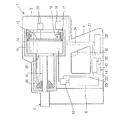
図1は、本発明に係る、ハウジング2を備える打ち込み機1の縦断面を模式的に示す。ハウジング2は、打ち込み機1を手にもって操作しうるようにするためのグリップ部4を有している。ファスナーは、打ち込み機1から押し付け部5を経由して飛び出し、被打ち込み材に打ち込まれる。
FIG. 1 schematically shows a longitudinal section of a driving machine 1 having a
被打ち込み材にファスナーを打ち込むために必要なエネルギーは、打ち込み機1に収容されたカートリッジ式のガスタンク8から与えられる。ガスタンク8は、制御可能な計量弁10を介して、燃焼室12と接続しうるようになっている。ガスタンク8から放出されたガスは、燃焼室12内で空気と混合されて可燃性の混合ガスとなる。この混合ガスは、ボルト、釘等のファスナーを被打ち込み材に打ち込む際に点火される。
The energy required for driving the fastener into the workpiece is supplied from a cartridge
燃焼室12は、ハウジング2内において、シリンダ14によって区画されている。燃焼室12の一方の側(シリンダ14の正面側)は、移動する壁体15によって密封されている。壁体15は、モータ16を駆動させると、ギヤボックス17を介して、矢印18で示す方向に移動(前進後退)する。壁体15が移動すると、燃焼室12の容積は、簡単な機構を経て、矢印18の方向に変化する。
The
燃焼室12の容積および/または移動可能な壁体15の位置は、センサ20によって検知される。センサ20は、センサ用ケーブル21を介して、コントローラ25と接続されている。一方、コントローラ25は、モータ16を制御しうるよう、コントローラ用ケーブル26を介して、モータ16と接続されている。コントローラ25は、アキュムレータ28(例えばバッテリ)から電気エネルギーを供給される。さらに、コントローラ25は、計量弁10を制御しうるよう、コントローラ用ケーブル29を介して、計量弁10と制御的に接続されている。
The volume of the
燃焼室12における壁体15の他の側は密封されており、特に壁体15の反対側は、ピストン34のヘッド部32によって密封されている。ピストン34は、一方の側では、シリンダ14内に位置するヘッド部32と一体となっており、他方の側(ヘッド部32の反対側)では、ガイドスリーブ内を案内される。ピストン34は、ガイドスリーブ内を案内される際には、クッション38を貫通して延出する。ファスナーを打ち込む際のピストン34の動きは、ファスナーによる制動に加えて、過大なエネルギーが発生した際にはクッション38を介しても制動される。
The other side of the
ファスナーの打ち込みは、グリップ部4に位置するトリガー42を手で握る(たとえば人差し指で引く)ことにより開始する。打ち込み機1は、トリガー42の外に、操作要素45を含む操作器44を備えている。
The driving of the fastener is started by grasping the
打ち込み機1は、トリガー42と補助装置44の外に、打ち込み機を駆動するエネルギーに係る情報を示す表示装置55を備えている。表示装置55は、コントローラ25と接続されており、モノクロのディスプレイを備えている。ディスプレイには、エネルギーに係る情報が、英数字または図形(例えば記号)を使って表示される。表示装置55は、このディスプレイに代えて、またはこのディスプレイに加えて、カラースクリーンを備えることもできる。
In addition to the
打ち込み機1を操作する作業員は、前記操作要素45に対して、打ち込みに係るエネルギーの目標値を入力することができる。入力された目標値、および/または、用途(例えば、低いエネルギー値に対しては「木材」を、中程度のエネルギー値に対しては「コンクリート」を、高いエネルギー値に対して「スチール」を用途とする)は、表示装置55に表示される。実際に打ち込み機1によって出力され得る、打ち込みに係る最大・最小のエネルギー(出力可能エネルギー)は、表示装置55を介して表示される。入力された目標値が、前記出力可能エネルギーの上限を超え、もしくは下限を下回った場合には、作業員は、表示装置55の表示やブザーによって警告を受ける。
An operator who operates the driving machine 1 can input a target value of energy related to driving to the
打ち込み機1を操作するに当たっては、目標の打ち込みエネルギーを実現するために、コントローラ25を使い、好ましくは気温や気圧等周囲の状況に係るパラメータを考慮して、望ましい燃焼室の容積、および必要なガスの供給量を推定する。燃焼室の容積を望ましいものに調整するため、コントローラ25は、モータ16に信号を与える。
In operating the driving machine 1, in order to achieve the target driving energy, the
モータ16は、好ましくはサーボモータとして働き、ギヤボックス17を介して燃焼室の壁体15を移動させる。ギヤボックス17は、壁体15をギヤボックス17に向かって動かすように燃焼室の圧力が作用する際には、自ら停止して、壁体15をそのときの位置に止まらせるように働くのが好ましい。さらに、ギヤボックス17は、燃焼室の圧力がモータ16の作動に影響を及ぼさないように構成するのが好ましい。
The
燃焼室の容積を望ましいものに調整するためのデータは、コントローラ25に格納されている。作業員が入力したエネルギーの目標値と、これに関連する、コントローラに格納されているかまたはセンサにより推定される壁体15の位置の値との間にずれがある場合には、ギヤボックス17を介して燃焼室の容積を調整するモータ16をどのくらい動かすかの指令値が算出される。
Data for adjusting the volume of the combustion chamber to a desired one is stored in the
打ち込み機1は、燃焼室の容積の調整をやり直すためのリセット機能を有するのが好ましい。このリセット機能は、例えば作業員の動作により開始される。例えばアキュムレータ28またはガスタンク8を取り付けることにより、リセットを実行するようにすることができる。リセットの際には、燃焼室の容積の調整機構、例えば、ギヤボックス17または壁体15は、ストッパに向かって動かされる。
The driving machine 1 preferably has a reset function for redoing the adjustment of the volume of the combustion chamber. This reset function is started, for example, by the operation of an operator. For example, the reset can be executed by attaching the
リセットは、次の2つの方法で行うことができる。1つは、モータ16(ステッピングモータ)を、ギヤボックス17または壁体15が所定の位置に復帰するのに十分に大きなステップ(回転角度)分回転するものである。ギヤボックス17または壁体15が所定の位置に復帰しても、モータ16には、給電が続けられるが、ギヤボックス17または壁体15はそれ以上動かない。このため、モータ16の回転角度は変化しない。もう1つは、モータ16の電流−電圧特性を予め計測しておき、ついで、ギヤボックス17または壁体15が所定の停止位置に復帰して、この電流−電圧特性に変化が生じたら、モータ16を停止させるというものである。
The reset can be performed by the following two methods. One is to rotate the motor 16 (stepping motor) by a step (rotation angle) sufficiently large so that the
本発明の他の実施形態によれば、実際の燃焼室の容積は、センサ20によって計測される。燃焼室の目標の容積と対比した結果、壁体15の位置について調整が必要な場合には、モータ16を動かし、ギヤボックス17を経て行うことができる。センサ20を使用する場合には、前述の位置確定のためのリセット機能を用いないこともできる。
According to another embodiment of the invention, the actual combustion chamber volume is measured by the
計量弁10は、電気的に作動し、閉止位置には圧力を加えなくても止まるようになっている。打ち込み機1を操作する場合には、計量弁10は、コントローラ25によって制御され、所定の時間にわたって開放される。計量弁10が開放している間、燃料としてのガスは、ガスタンク8から燃焼室12へ流れる。計量弁10の開放時間を変化させれば、ガスの送給量を調整することができる。
The
Claims (12)
前記燃焼室(12)の容積を調整する装置およびガスの送給量を計量する計量弁(10)と制御的に接続されたコントローラ(25)を備えていることを特徴とする打ち込み機。 A piston including a piston (34) that can be moved linearly instantaneously by igniting a combustible gas mixture in a combustion chamber (12) whose volume can be changed, and a fastener including a case where it is a bolt or a nail is driven. In the driving machine (1) for driving into the material,
A driving machine comprising a controller (25) connected in control with a device for adjusting the volume of the combustion chamber (12) and a metering valve (10) for metering a gas supply amount.
Applications Claiming Priority (2)
| Application Number | Priority Date | Filing Date | Title |
|---|---|---|---|
| DE102010063177.9 | 2010-12-15 | ||
| DE102010063177A DE102010063177A1 (en) | 2010-12-15 | 2010-12-15 | A bolt gun and method for operating a bolt gun |
Publications (2)
| Publication Number | Publication Date |
|---|---|
| JP2012125920A true JP2012125920A (en) | 2012-07-05 |
| JP6009762B2 JP6009762B2 (en) | 2016-10-19 |
Family
ID=45350642
Family Applications (1)
| Application Number | Title | Priority Date | Filing Date |
|---|---|---|---|
| JP2011273680A Active JP6009762B2 (en) | 2010-12-15 | 2011-12-14 | Driving machine and driving method thereof |
Country Status (8)
| Country | Link |
|---|---|
| US (1) | US9687975B2 (en) |
| EP (1) | EP2465643B1 (en) |
| JP (1) | JP6009762B2 (en) |
| CN (1) | CN102528754B (en) |
| AU (1) | AU2011254075C1 (en) |
| CA (1) | CA2761540A1 (en) |
| DE (1) | DE102010063177A1 (en) |
| TW (1) | TW201240777A (en) |
Families Citing this family (9)
| Publication number | Priority date | Publication date | Assignee | Title |
|---|---|---|---|---|
| EP2875902A1 (en) * | 2013-11-26 | 2015-05-27 | HILTI Aktiengesellschaft | Setting device with temperature sensor |
| EP2886259A1 (en) * | 2013-12-18 | 2015-06-24 | HILTI Aktiengesellschaft | Driving device |
| EP2886258A1 (en) * | 2013-12-18 | 2015-06-24 | HILTI Aktiengesellschaft | Driving device |
| EP3034239A1 (en) * | 2014-12-19 | 2016-06-22 | HILTI Aktiengesellschaft | Driving device with adjustable combustion chamber |
| US20180243891A1 (en) * | 2015-09-14 | 2018-08-30 | Hilti Aktiengesellschaft | Fuel gas-fired driving-in tool with charging function |
| EP3184248A1 (en) | 2015-12-22 | 2017-06-28 | HILTI Aktiengesellschaft | Combustion-driven setting tool and method for operating such a setting tool |
| EP3184251A1 (en) * | 2015-12-22 | 2017-06-28 | HILTI Aktiengesellschaft | Combustion-driven setting tool and method for operating such a setting tool |
| EP3199301A1 (en) * | 2016-02-01 | 2017-08-02 | HILTI Aktiengesellschaft | Combustion chamber and driving tool |
| US10974378B2 (en) * | 2017-02-03 | 2021-04-13 | Tricord Solutions, Inc. | Fastener driving apparatus |
Citations (7)
| Publication number | Priority date | Publication date | Assignee | Title |
|---|---|---|---|---|
| JPS6328576A (en) * | 1986-07-02 | 1988-02-06 | センコ、プロダクツ、インコ | Cam control built-in internal combustion type fastener driving tool |
| US6318615B1 (en) * | 1995-05-23 | 2001-11-20 | Applied Tool Development Corporation | Internal combustion powered tool |
| US6321968B1 (en) * | 1998-09-10 | 2001-11-27 | Senco Products, Inc. | Combustion chamber design for propellant charges and power adjustment means |
| JP2001525262A (en) * | 1997-12-04 | 2001-12-11 | ゲルト、ケルナー | Device for fixing mounting element to installation base and use of this device |
| JP2006305660A (en) * | 2005-04-27 | 2006-11-09 | Makita Corp | Combustion type working tool |
| JP2007510552A (en) * | 2003-11-03 | 2007-04-26 | イリノイ トゥール ワークス インコーポレイティド | Combustion device with a shrinkable volume |
| JP2009095935A (en) * | 2007-10-17 | 2009-05-07 | Max Co Ltd | Gas combustion type driving tool |
Family Cites Families (29)
| Publication number | Priority date | Publication date | Assignee | Title |
|---|---|---|---|---|
| FR2463267A1 (en) * | 1979-08-08 | 1981-02-20 | Liesse Maurice | THERMAL GENERATOR OF PULSES |
| US4773581A (en) * | 1986-06-13 | 1988-09-27 | Hitachi Koki Company, Ltd. | Combustion gas powered tool |
| DE4032204C2 (en) * | 1990-10-11 | 1999-10-21 | Hilti Ag | Setting tool for fasteners |
| DE4032202C2 (en) * | 1990-10-11 | 1999-10-21 | Hilti Ag | Setting tool for fasteners |
| US5592580A (en) * | 1994-11-10 | 1997-01-07 | Illinois Tool Works Inc. | System for controlling energy output of combustion-powered, fastener-driving tool |
| US5752643A (en) * | 1995-05-23 | 1998-05-19 | Applied Tool Development Corporation | Internal combustion powered tool |
| AUPN585495A0 (en) * | 1995-10-09 | 1995-11-02 | Ramset Fasteners (Aust.) Pty. Limited | Power actuated tools with power adjustment means |
| US6260519B1 (en) * | 1997-12-31 | 2001-07-17 | Porter-Cable Corporation | Internal combustion fastener driving tool accelerator plate |
| DE19950352C2 (en) * | 1999-10-19 | 2002-03-07 | Hilti Ag | Portable, combustion powered tool and method for driving its piston |
| DE19950350C2 (en) * | 1999-10-19 | 2002-06-20 | Hilti Ag | Dosing head, in particular for setting tools operated by internal combustion engines |
| DE19950345C2 (en) * | 1999-10-19 | 2003-06-05 | Hilti Ag | Method and device for driving a piston of an internal combustion-powered working device, in particular a setting device for fastening elements |
| DE19962711C2 (en) * | 1999-12-23 | 2002-06-27 | Hilti Ag | Portable, combustion powered tool with changeable prechamber |
| DE19962599C2 (en) * | 1999-12-23 | 2002-09-19 | Hilti Ag | Portable, combustion-powered working tool, in particular setting tool for fastening elements, and method for its operational control |
| DE19962695B4 (en) | 1999-12-23 | 2006-02-16 | Hilti Ag | Portable, combustion-powered work tool with variable main chamber |
| DE19962598C2 (en) * | 1999-12-23 | 2002-03-14 | Hilti Ag | Portable, combustion-powered working device, in particular setting device for fastening elements and method for its operational control |
| DE19962597C2 (en) * | 1999-12-23 | 2002-07-04 | Hilti Ag | Portable, combustion powered tool and method for providing a gas mixture in its combustion chamber |
| DE10226878A1 (en) * | 2002-06-17 | 2003-12-24 | Hilti Ag | Gas powered setting tool |
| US6739490B1 (en) * | 2002-06-24 | 2004-05-25 | Illinois Tool Works Inc. | Fastener supply and positioning mechanism for a tool |
| US6796476B2 (en) * | 2002-09-11 | 2004-09-28 | Illinois Tool Works Inc. | Power control system for a framing tool |
| DE10259816B4 (en) | 2002-12-19 | 2005-01-20 | Hilti Ag | Internal combustion engine, in particular setting device with volumetric, gaseous dosage |
| DE10260703A1 (en) * | 2002-12-23 | 2004-07-01 | Hilti Ag | Combustion-powered setting tool |
| FR2852546B1 (en) * | 2003-03-19 | 2006-08-11 | Prospection & Inventions | METHODS FOR ADJUSTING THE POWER OF A GAS-OPERATING APPARATUS |
| DE10319647B3 (en) * | 2003-05-02 | 2004-09-02 | Hilti Ag | Setting device for attachment elements, e.g. nails, bolts or pins, has reader of attachment element magazine strip coding, controller for adjusting setting parameters depending on coding data |
| US6892524B1 (en) * | 2003-11-03 | 2005-05-17 | Illinois Tool Works Inc. | Latching mechanism for combustion chamber plate of a fastener driving tool |
| DE102004043955B4 (en) * | 2004-09-11 | 2006-07-20 | Hilti Ag | Internal combustion setting device |
| DE102004043950B4 (en) * | 2004-09-11 | 2006-10-12 | Hilti Ag | Internal combustion setting device |
| DE102005000032A1 (en) | 2005-04-12 | 2006-10-19 | Hilti Ag | Internal combustion setting device |
| DE102006000179A1 (en) * | 2006-04-13 | 2007-10-18 | Hilti Ag | Internal combustion setting device |
| US7918374B2 (en) * | 2007-01-29 | 2011-04-05 | Halex/Scott Fetzer Company | Portable fastener driving device |
-
2010
- 2010-12-15 DE DE102010063177A patent/DE102010063177A1/en not_active Withdrawn
-
2011
- 2011-11-15 TW TW100141562A patent/TW201240777A/en unknown
- 2011-11-17 EP EP11189461.4A patent/EP2465643B1/en active Active
- 2011-12-12 CN CN201110410237.3A patent/CN102528754B/en active Active
- 2011-12-13 CA CA2761540A patent/CA2761540A1/en not_active Abandoned
- 2011-12-14 US US13/326,053 patent/US9687975B2/en active Active
- 2011-12-14 JP JP2011273680A patent/JP6009762B2/en active Active
- 2011-12-15 AU AU2011254075A patent/AU2011254075C1/en active Active
Patent Citations (7)
| Publication number | Priority date | Publication date | Assignee | Title |
|---|---|---|---|---|
| JPS6328576A (en) * | 1986-07-02 | 1988-02-06 | センコ、プロダクツ、インコ | Cam control built-in internal combustion type fastener driving tool |
| US6318615B1 (en) * | 1995-05-23 | 2001-11-20 | Applied Tool Development Corporation | Internal combustion powered tool |
| JP2001525262A (en) * | 1997-12-04 | 2001-12-11 | ゲルト、ケルナー | Device for fixing mounting element to installation base and use of this device |
| US6321968B1 (en) * | 1998-09-10 | 2001-11-27 | Senco Products, Inc. | Combustion chamber design for propellant charges and power adjustment means |
| JP2007510552A (en) * | 2003-11-03 | 2007-04-26 | イリノイ トゥール ワークス インコーポレイティド | Combustion device with a shrinkable volume |
| JP2006305660A (en) * | 2005-04-27 | 2006-11-09 | Makita Corp | Combustion type working tool |
| JP2009095935A (en) * | 2007-10-17 | 2009-05-07 | Max Co Ltd | Gas combustion type driving tool |
Also Published As
| Publication number | Publication date |
|---|---|
| US20120153002A1 (en) | 2012-06-21 |
| TW201240777A (en) | 2012-10-16 |
| CN102528754A (en) | 2012-07-04 |
| AU2011254075B2 (en) | 2014-06-26 |
| EP2465643A3 (en) | 2015-10-14 |
| DE102010063177A1 (en) | 2012-06-21 |
| AU2011254075A1 (en) | 2012-07-05 |
| CN102528754B (en) | 2015-12-16 |
| CA2761540A1 (en) | 2012-06-15 |
| AU2011254075C1 (en) | 2014-11-06 |
| US9687975B2 (en) | 2017-06-27 |
| JP6009762B2 (en) | 2016-10-19 |
| EP2465643A2 (en) | 2012-06-20 |
| EP2465643B1 (en) | 2016-09-07 |
Similar Documents
| Publication | Publication Date | Title |
|---|---|---|
| JP6009762B2 (en) | Driving machine and driving method thereof | |
| JP5864052B2 (en) | Driving machine and operation method of driving machine | |
| US6796476B2 (en) | Power control system for a framing tool | |
| DE102014018335B4 (en) | driving tool | |
| AU2003204874B2 (en) | An improved fastener supply and positioning mechanism for a tool | |
| US20130270319A1 (en) | Fastener driving tool | |
| AU2014292183B2 (en) | Control method and hand-held machine tool | |
| US20130087108A1 (en) | Combustion-engined setting tool | |
| AU2014292187A1 (en) | Control method and hand tool machine | |
| JP6636160B2 (en) | Fuel-powered driving device and method of operating the driving device | |
| EP3461591B1 (en) | Driving tool | |
| CA2810976C (en) | Hand-held work apparatus and method for operating a hand-held work apparatus | |
| JP2012111036A (en) | Riveting machine | |
| JP5893902B2 (en) | Nailer |
Legal Events
| Date | Code | Title | Description |
|---|---|---|---|
| A621 | Written request for application examination |
Free format text: JAPANESE INTERMEDIATE CODE: A621 Effective date: 20141024 |
|
| A977 | Report on retrieval |
Free format text: JAPANESE INTERMEDIATE CODE: A971007 Effective date: 20150708 |
|
| A131 | Notification of reasons for refusal |
Free format text: JAPANESE INTERMEDIATE CODE: A131 Effective date: 20150902 |
|
| A601 | Written request for extension of time |
Free format text: JAPANESE INTERMEDIATE CODE: A601 Effective date: 20151201 |
|
| A601 | Written request for extension of time |
Free format text: JAPANESE INTERMEDIATE CODE: A601 Effective date: 20151203 |
|
| A521 | Request for written amendment filed |
Free format text: JAPANESE INTERMEDIATE CODE: A523 Effective date: 20160302 |
|
| TRDD | Decision of grant or rejection written | ||
| A01 | Written decision to grant a patent or to grant a registration (utility model) |
Free format text: JAPANESE INTERMEDIATE CODE: A01 Effective date: 20160831 |
|
| A61 | First payment of annual fees (during grant procedure) |
Free format text: JAPANESE INTERMEDIATE CODE: A61 Effective date: 20160915 |
|
| R150 | Certificate of patent or registration of utility model |
Ref document number: 6009762 Country of ref document: JP Free format text: JAPANESE INTERMEDIATE CODE: R150 |
|
| R250 | Receipt of annual fees |
Free format text: JAPANESE INTERMEDIATE CODE: R250 |
|
| R250 | Receipt of annual fees |
Free format text: JAPANESE INTERMEDIATE CODE: R250 |
|
| R250 | Receipt of annual fees |
Free format text: JAPANESE INTERMEDIATE CODE: R250 |
|
| R250 | Receipt of annual fees |
Free format text: JAPANESE INTERMEDIATE CODE: R250 |
|
| R250 | Receipt of annual fees |
Free format text: JAPANESE INTERMEDIATE CODE: R250 |