JP2012125603A - Coffee dripper - Google Patents
Coffee dripper Download PDFInfo
- Publication number
- JP2012125603A JP2012125603A JP2012061810A JP2012061810A JP2012125603A JP 2012125603 A JP2012125603 A JP 2012125603A JP 2012061810 A JP2012061810 A JP 2012061810A JP 2012061810 A JP2012061810 A JP 2012061810A JP 2012125603 A JP2012125603 A JP 2012125603A
- Authority
- JP
- Japan
- Prior art keywords
- dripper
- container
- frame
- frame body
- lid
- Prior art date
- Legal status (The legal status is an assumption and is not a legal conclusion. Google has not performed a legal analysis and makes no representation as to the accuracy of the status listed.)
- Granted
Links
- 210000000988 bone and bone Anatomy 0.000 claims abstract description 14
- 229920003002 synthetic resin Polymers 0.000 claims abstract description 6
- 239000000057 synthetic resin Substances 0.000 claims abstract description 6
- 239000002184 metal Substances 0.000 claims description 4
- 238000004519 manufacturing process Methods 0.000 abstract description 5
- 238000005406 washing Methods 0.000 abstract 1
- 235000013361 beverage Nutrition 0.000 description 9
- 210000000078 claw Anatomy 0.000 description 6
- 239000000843 powder Substances 0.000 description 3
- 230000002093 peripheral effect Effects 0.000 description 2
- 238000004140 cleaning Methods 0.000 description 1
- 230000003670 easy-to-clean Effects 0.000 description 1
- 239000011521 glass Substances 0.000 description 1
- 230000001771 impaired effect Effects 0.000 description 1
- XLYOFNOQVPJJNP-UHFFFAOYSA-N water Substances O XLYOFNOQVPJJNP-UHFFFAOYSA-N 0.000 description 1
Images


Abstract
Description
この発明は、容器に嵌合させた状態でコーヒーの抽出を行い、容器の蓋を閉じた状態で、飲料を容器から注ぎ出すことができるコーヒードリッパーに関する。 The present invention relates to a coffee dripper capable of extracting coffee in a state of being fitted in a container and pouring a beverage from the container in a state of closing the lid of the container.
従来、ドリッパーを容器に嵌合させた状態でコーヒー等の飲料の抽出を行い、容器の蓋を閉じてドリッパーに係合させた状態で、飲料を容器から注ぎ出すことができる飲料抽出器が知られている(特許文献1参照)。
この飲料抽出器においては、ドリッパーが、こし網付きの漏斗と、この漏斗を囲んで下方へ円筒状に延出するスカートとを有する。スカートは、外周に係合突起を有し、容器の内側の係合突部に弾性的に嵌合する。スカートは、飲料を注ぎ出すときに通路を形成するための開放部を有する。
2. Description of the Related Art Conventionally, there has been known a beverage extractor that can extract a beverage such as coffee with a dripper fitted in a container, and can pour the beverage out of the container with the lid closed and engaged with the dripper. (See Patent Document 1).
In this beverage extractor, the dripper has a funnel with a strainer and a skirt that extends cylindrically downward around the funnel. The skirt has an engagement protrusion on the outer periphery, and is elastically fitted to the engagement protrusion inside the container. The skirt has an opening for forming a passage when the beverage is poured out.
上記従来の飲料抽出器におけるドリッパーは、構造が複雑で、容器に対する装着、取り外し、洗浄が必ずしも容易でなく、製造コストも大きくなるという問題点がある。
したがって、この出願に係る発明は、構造が簡単で、装着、取り外し、洗浄が容易で、製造コストも減じることができるドリッパーを提供することを課題としている。
The dripper in the conventional beverage extractor has a complicated structure, and it is not always easy to attach, remove, and wash the container, and there is a problem that the manufacturing cost increases.
Accordingly, an object of the invention according to this application is to provide a dripper that has a simple structure, can be easily mounted, removed, and cleaned, and can reduce manufacturing costs.
上記課題を解決するため、この出願に係る発明においては、合成樹脂製の枠体11と、この枠体11と共にインサート成型される金属製のメッシュ12とを具備させてコーヒードリッパー3を構成する。枠体11は、円環状の環状枠13と、この環状枠13からそれの円周方向に所定の相互間隔を置いてそれぞれ下方へ延出し、下端において環状枠13の中心軸に集合一体化する複数の支持骨15とを具備する。メッシュ12は、環状枠13と各支持骨15間及び各支持骨15相互間に渡るように張設され、それによって、枠体11と共に概略円錐筒状をなすように形成する。
また、支持骨15は、下方へそれぞれ渦巻き状に湾曲して延出させる。
In order to solve the above problems, in the invention according to this application, the
Further, the
この出願に係る発明のドリッパー3によれは、単純な円錐筒形であるから、洗浄が容易であるし、容器2に嵌合させ易く容器2に対して容易に着脱でき、また製造コストも減じることができる。
According to the
図面を参照してこの発明の実施の形態を説明する。
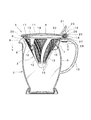
図1から図4において、飲料サーバー1は、耐熱ガラス製の容器2と、容器に着脱自在に嵌合されるドリッパー3と、蓋4とを具備する。
Embodiments of the present invention will be described with reference to the drawings.
1 to 4, the
容器2は、上方に開口5を有する横断面ほぼ円形の側壁6を具備する。容器の側壁6は、内径が縮小した隘部7と注口8とを上部に具備する。注口8は、側壁6の一部を半径方向外側へ断面ほぼV字状に膨出させることにより内側に形成される溝部9によって構成される。溝部9は容器2の上縁から隘部7より下方位置まで側壁6の内側を縦方向に伸びる。容器2の取手10は、上端が当該容器2の上縁付近の側壁6に接続し、そこから半径方向外側へほぼ水平に延出した後、下方内側へ湾曲し、下端が側壁6の外側下部に一体に接続する。
The
ドリッパー3は、全体が、下方に縮小する円錐筒状で、容器1の開口5内に着脱自在に嵌合される。ドリッパー3は、合成樹脂で一体成形された枠体11と、枠体11と共にインサート成型された金属製のメッシュ12とからなる。枠体11は、環状枠13と、摘み14と、支持骨15とを具備する。
The
上端の環状枠13は円環状で、容器2の上縁に載る鍔部を有する。摘み14は、環状枠13の鍔部から半径方向外側へ水平に延出する。6本の支持骨15は、環状枠13から円周方向に等間隔に、下方へそれぞれ渦巻き状に湾曲して延出し、下端において収束して互いに一体に接続する。
The upper
ドリッパー3の外周に相互に120°の間隔で位置する3つの支持骨15の中間部、同高さ位置には、それぞれ半径方向外側へ突出する係合突起16が形成される。この係合突起16は、図5(a)に示すように、そのいずれか1つを注口8内に配置して、ドリッパー3を容器2の開口5内に挿入したときにのみ、隘部7を上下方向に通過可能な相互関係で配置される。そして、係合突起16が隘部7を下方へ通過して、環状枠13が容器2の上縁に載った後、ドリッパー3を水平回転させて、図5(b)に示すように、当該1つの係合突起16を注口8に対応する位置からずらすとドリッパー3は、係合突起16によって上方へ外れ止めされる。
On the outer periphery of the
蓋4は、容器2の開口5およびドリッパー3の開口17を開閉できるように、取手10の上部に結合されたヒンジ18を介して容器2に結合される。蓋4は、合成樹脂で一体成型され、円盤状の主体部19と、その周縁部に形成された係合爪20、指掛け片21を具備する。係合爪20は、主体部19の周縁に沿い、湾曲してわずかに下方へ延出しており、ドリッパー3の環状枠13に弾性的に係合することができる。係合爪20は、主体部19の外周の一部で欠落し、切欠部22が設けられる。指掛け片21は、主体部19の周縁から半径方向外側に向かって上昇するように傾斜して延出する。
The
ヒンジ18の一部を構成するブラケット23と軸部24は、指掛け片21から下方へ延出するように形成される。軸部24は、ブラケット23の対向内面から一対突出しており、それぞれ長円柱状である。ヒンジ18の他の一部を構成する軸受け部材25は、容器2の取手10に固着される。軸受け部材25は、一対の軸部24を着脱自在に受け入れて、これを回転自在に支持する。
The
図7ないし図9に示すように、軸受け部材25は、弾性合成樹脂で一体成形され、第1および第2の軸受け部26,27と、これらの軸受け部26,27間を接続する帯状部28とを具備する。第1および第2の軸受け部26,27は、容器の取手10上で互いにスナップ係合することにより一体に結合して軸受けを形成する。一方の軸受け部27は、容器2の上縁部に係合する係合片29を具備する。帯状部27は、軸受け部26,27の相互係合状態において取手10を巻き締めるように構成される。取手10は、製造上、寸法誤差が比較的大きいが、帯状部28は、この寸法誤差を考慮して設計される。帯状部28による取手10の締め付けが弱い場合でも、係合片29が容器2の上縁部に係合するので、軸受け部材25は取手10上に確実に固定される。
As shown in FIGS. 7 to 9, the
この飲料サーバー1を使用する場合には、蓋4を起立させた状態で、図5(a)に示すように、ドリッパー3の1つの係合突起16が容器2の溝部9(注口8)に対応する相対回転角度位置で、ドリッパー3を容器2に嵌合させると、3つの係合突起16は隘部7を通過して、隘部7の下方に配置される。この状態で、図5(b)に示す位置まで(図示の実施形態においては摘みがヒンジ18に当接する位置付近まで)ドリッパー3を時計方向へ回転させると、ドリッパー3は容器2から抜け止めされる。例えば、ドリッパー3にコーヒー粉を入れて、熱湯を所定量注ぎ、コーヒーを抽出した後、ドリッパー3を取り外さずに、蓋4を転倒させて押さえると、係合爪20がドリッパー3の環状枠13の外周に係合して蓋4が開き止めされる。図示の実施形態においては、ドリッパー3が時計方向へ所定位置まで回転されていれば、摘み14が蓋4の切欠部22に対応するので、蓋4を閉じることができるが、所定位置にないと、摘み14が蓋4の係合爪20に当接して蓋4を閉じることができない。蓋4を閉じた状態で、容器2を傾ければ、コーヒーを注口8から注ぎ出すことができる。容器2を傾けても、係合突起16が隘部7に係合しているので、ドリッパー3は容器2から脱落することがない。また、ドリッパー3は円錐形であるから、容器2を傾けたときに、コーヒーの流れを遮ることがない。蓋4が閉じているので、コーヒー粉が露出して体裁を損ねることも、またコーヒー粉がこぼれ落ちることもない。容器2と蓋3には金属部品が使用されていないから、ドリッパー3を外して蓋4を閉じた状態で、電子レンジでコーヒーを再加熱することもできる。ドリッパー3は、単純な円錐筒形であるから、洗浄が容易である。蓋4も容器2から外して容易に洗浄できる。容器2とドリッパー4を組んだ状態でコンパクトに保管できる。
When the
1 サーバー
2 容器
3 ドリッパー
4 蓋
5 開口
6 側壁
7 隘部
8 注口
9 溝部
10 取手
11 枠体
12 メッシュ
13 環状枠
14 摘み
15 支持骨
16 係合突起
17 ドリッパーの開口
18 ヒンジ
19 主体部
20 係合爪
21 指掛け片
22 切欠部
23 ブラケット
24 軸部
25 軸受け部材
26 第1の軸受け部
27 第2の軸受け部
28 帯状部
29 係合片
DESCRIPTION OF
Claims (2)
Priority Applications (1)
| Application Number | Priority Date | Filing Date | Title |
|---|---|---|---|
| JP2012061810A JP5651624B2 (en) | 2012-03-19 | 2012-03-19 | Coffee dripper |
Applications Claiming Priority (1)
| Application Number | Priority Date | Filing Date | Title |
|---|---|---|---|
| JP2012061810A JP5651624B2 (en) | 2012-03-19 | 2012-03-19 | Coffee dripper |
Related Parent Applications (1)
| Application Number | Title | Priority Date | Filing Date |
|---|---|---|---|
| JP2007120144A Division JP2008272260A (en) | 2007-04-27 | 2007-04-27 | Drink server |
Publications (2)
| Publication Number | Publication Date |
|---|---|
| JP2012125603A true JP2012125603A (en) | 2012-07-05 |
| JP5651624B2 JP5651624B2 (en) | 2015-01-14 |
Family
ID=46643295
Family Applications (1)
| Application Number | Title | Priority Date | Filing Date |
|---|---|---|---|
| JP2012061810A Active JP5651624B2 (en) | 2012-03-19 | 2012-03-19 | Coffee dripper |
Country Status (1)
| Country | Link |
|---|---|
| JP (1) | JP5651624B2 (en) |
Cited By (1)
| Publication number | Priority date | Publication date | Assignee | Title |
|---|---|---|---|---|
| CN103705062A (en) * | 2012-09-29 | 2014-04-09 | 郑荣波 | Multifunctional teapot |
Citations (4)
| Publication number | Priority date | Publication date | Assignee | Title |
|---|---|---|---|---|
| JPS6024233U (en) * | 1983-07-26 | 1985-02-19 | アルプス商事株式会社 | teaware spout device |
| JPH0159464U (en) * | 1987-10-09 | 1989-04-14 | ||
| JP2000037297A (en) * | 1998-07-24 | 2000-02-08 | Yasuhisa Masuzawa | Coffee maker |
| JP2000152877A (en) * | 1998-11-19 | 2000-06-06 | Sanyo Electric Co Ltd | Basket and device for producing extracted drink |
-
2012
- 2012-03-19 JP JP2012061810A patent/JP5651624B2/en active Active
Patent Citations (4)
| Publication number | Priority date | Publication date | Assignee | Title |
|---|---|---|---|---|
| JPS6024233U (en) * | 1983-07-26 | 1985-02-19 | アルプス商事株式会社 | teaware spout device |
| JPH0159464U (en) * | 1987-10-09 | 1989-04-14 | ||
| JP2000037297A (en) * | 1998-07-24 | 2000-02-08 | Yasuhisa Masuzawa | Coffee maker |
| JP2000152877A (en) * | 1998-11-19 | 2000-06-06 | Sanyo Electric Co Ltd | Basket and device for producing extracted drink |
Cited By (1)
| Publication number | Priority date | Publication date | Assignee | Title |
|---|---|---|---|---|
| CN103705062A (en) * | 2012-09-29 | 2014-04-09 | 郑荣波 | Multifunctional teapot |
Also Published As
| Publication number | Publication date |
|---|---|
| JP5651624B2 (en) | 2015-01-14 |
Similar Documents
| Publication | Publication Date | Title |
|---|---|---|
| JP2011056254A5 (en) | ||
| TWM544259U (en) | Filtering and brewing pot for preventing lid from dropping | |
| KR101499112B1 (en) | Removable type Cover Handle for Cookware | |
| JP2022529851A (en) | Cooking container lid with auxiliary lid | |
| JP5651624B2 (en) | Coffee dripper | |
| JP2008272260A (en) | Drink server | |
| US11457755B2 (en) | Teapot | |
| JP2008272260A5 (en) | ||
| KR200452884Y1 (en) | Window fixing member of cooking vessel lid | |
| RU165953U1 (en) | MULTIFUNCTIONAL COVER WITH OPEN CAP | |
| CN210446515U (en) | Self-inclined draining cup and kit | |
| JP4805420B1 (en) | Extractor | |
| JP3139389U (en) | Teapot for deep steamed tea | |
| CN208435278U (en) | A kind of improvement structure of glass material kettle | |
| CN101947054A (en) | Fastening structure of pressure cooker | |
| CN205514158U (en) | Structure is covered with opening and shutting of utensil in kitchen | |
| KR200331944Y1 (en) | A teacup having a filter | |
| KR20090089640A (en) | A teacup | |
| JP3175634U (en) | Liquid storage container | |
| KR200460733Y1 (en) | A soup caldron with a drip pan | |
| CN204363591U (en) | A kind of Water-cleaning tea pot | |
| CN211175335U (en) | Sealing ring and simple tea making cup comprising same | |
| CN218419303U (en) | Cup cover and cup | |
| CN215190993U (en) | Lid and pan | |
| CN213075455U (en) | Draining basket |
Legal Events
| Date | Code | Title | Description |
|---|---|---|---|
| A621 | Written request for application examination |
Free format text: JAPANESE INTERMEDIATE CODE: A621 Effective date: 20120416 |
|
| A131 | Notification of reasons for refusal |
Free format text: JAPANESE INTERMEDIATE CODE: A131 Effective date: 20130710 |
|
| A521 | Request for written amendment filed |
Free format text: JAPANESE INTERMEDIATE CODE: A523 Effective date: 20130909 |
|
| A131 | Notification of reasons for refusal |
Free format text: JAPANESE INTERMEDIATE CODE: A131 Effective date: 20131023 |
|
| A521 | Request for written amendment filed |
Free format text: JAPANESE INTERMEDIATE CODE: A523 Effective date: 20131225 |
|
| A02 | Decision of refusal |
Free format text: JAPANESE INTERMEDIATE CODE: A02 Effective date: 20140731 |
|
| A521 | Request for written amendment filed |
Free format text: JAPANESE INTERMEDIATE CODE: A523 Effective date: 20140731 |
|
| A911 | Transfer to examiner for re-examination before appeal (zenchi) |
Free format text: JAPANESE INTERMEDIATE CODE: A911 Effective date: 20141001 |
|
| TRDD | Decision of grant or rejection written | ||
| A01 | Written decision to grant a patent or to grant a registration (utility model) |
Free format text: JAPANESE INTERMEDIATE CODE: A01 Effective date: 20141023 |
|
| A61 | First payment of annual fees (during grant procedure) |
Free format text: JAPANESE INTERMEDIATE CODE: A61 Effective date: 20141117 |
|
| R150 | Certificate of patent or registration of utility model |
Ref document number: 5651624 Country of ref document: JP Free format text: JAPANESE INTERMEDIATE CODE: R150 |
|
| R250 | Receipt of annual fees |
Free format text: JAPANESE INTERMEDIATE CODE: R250 |
|
| R250 | Receipt of annual fees |
Free format text: JAPANESE INTERMEDIATE CODE: R250 |
|
| R250 | Receipt of annual fees |
Free format text: JAPANESE INTERMEDIATE CODE: R250 |
|
| R250 | Receipt of annual fees |
Free format text: JAPANESE INTERMEDIATE CODE: R250 |
|
| R250 | Receipt of annual fees |
Free format text: JAPANESE INTERMEDIATE CODE: R250 |
|
| R250 | Receipt of annual fees |
Free format text: JAPANESE INTERMEDIATE CODE: R250 |
|
| R250 | Receipt of annual fees |
Free format text: JAPANESE INTERMEDIATE CODE: R250 |