JP2012123778A - Information processing apparatus, information processing method, and program - Google Patents
Information processing apparatus, information processing method, and program Download PDFInfo
- Publication number
- JP2012123778A JP2012123778A JP2011147414A JP2011147414A JP2012123778A JP 2012123778 A JP2012123778 A JP 2012123778A JP 2011147414 A JP2011147414 A JP 2011147414A JP 2011147414 A JP2011147414 A JP 2011147414A JP 2012123778 A JP2012123778 A JP 2012123778A
- Authority
- JP
- Japan
- Prior art keywords
- setting
- individual
- setting screen
- processing apparatus
- Prior art date
- Legal status (The legal status is an assumption and is not a legal conclusion. Google has not performed a legal analysis and makes no representation as to the accuracy of the status listed.)
- Granted
Links
Images


Classifications
-
- G—PHYSICS
- G06—COMPUTING OR CALCULATING; COUNTING
- G06F—ELECTRIC DIGITAL DATA PROCESSING
- G06F3/00—Input arrangements for transferring data to be processed into a form capable of being handled by the computer; Output arrangements for transferring data from processing unit to output unit, e.g. interface arrangements
- G06F3/12—Digital output to print unit, e.g. line printer, chain printer
- G06F3/1201—Dedicated interfaces to print systems
- G06F3/1202—Dedicated interfaces to print systems specifically adapted to achieve a particular effect
- G06F3/1203—Improving or facilitating administration, e.g. print management
- G06F3/1205—Improving or facilitating administration, e.g. print management resulting in increased flexibility in print job configuration, e.g. job settings, print requirements, job tickets
-
- G—PHYSICS
- G06—COMPUTING OR CALCULATING; COUNTING
- G06F—ELECTRIC DIGITAL DATA PROCESSING
- G06F3/00—Input arrangements for transferring data to be processed into a form capable of being handled by the computer; Output arrangements for transferring data from processing unit to output unit, e.g. interface arrangements
- G06F3/12—Digital output to print unit, e.g. line printer, chain printer
- G06F3/1201—Dedicated interfaces to print systems
- G06F3/1223—Dedicated interfaces to print systems specifically adapted to use a particular technique
- G06F3/1237—Print job management
- G06F3/1253—Configuration of print job parameters, e.g. using UI at the client
-
- G—PHYSICS
- G06—COMPUTING OR CALCULATING; COUNTING
- G06F—ELECTRIC DIGITAL DATA PROCESSING
- G06F3/00—Input arrangements for transferring data to be processed into a form capable of being handled by the computer; Output arrangements for transferring data from processing unit to output unit, e.g. interface arrangements
- G06F3/12—Digital output to print unit, e.g. line printer, chain printer
- G06F3/1201—Dedicated interfaces to print systems
- G06F3/1278—Dedicated interfaces to print systems specifically adapted to adopt a particular infrastructure
- G06F3/1285—Remote printer device, e.g. being remote from client or server
- G06F3/1287—Remote printer device, e.g. being remote from client or server via internet
-
- G—PHYSICS
- G06—COMPUTING OR CALCULATING; COUNTING
- G06F—ELECTRIC DIGITAL DATA PROCESSING
- G06F3/00—Input arrangements for transferring data to be processed into a form capable of being handled by the computer; Output arrangements for transferring data from processing unit to output unit, e.g. interface arrangements
- G06F3/12—Digital output to print unit, e.g. line printer, chain printer
- G06F3/1201—Dedicated interfaces to print systems
- G06F3/1223—Dedicated interfaces to print systems specifically adapted to use a particular technique
- G06F3/1224—Client or server resources management
- G06F3/1225—Software update, e.g. print driver, modules, plug-ins, fonts
Landscapes
- Engineering & Computer Science (AREA)
- Theoretical Computer Science (AREA)
- Human Computer Interaction (AREA)
- Physics & Mathematics (AREA)
- General Engineering & Computer Science (AREA)
- General Physics & Mathematics (AREA)
- Accessory Devices And Overall Control Thereof (AREA)
Abstract
Description
本発明は、情報処理装置、情報処理方法及びプログラムに関する。 The present invention relates to an information processing apparatus, an information processing method, and a program.
業務におけるビジネス文書の印刷において、ユーザーはオフィスLAN内のWindows(登録商標) PCからのプリンターへの出力が一般的であった。ユーザーは、プリンターに対応したプリンタードライバーの設定UIを操作して印刷設定を行う。
特許文献1は、印刷設定UI技術を開示している。サーバーに設置された仮想プリンタードライバーで設定UIを制御している。仮想プリンタードライバーは、下位の複数実プリンタードライバーに他社プリンターが含まるなら基礎的な設定UIにする。
しかしながら現在、ユーザーの業務環境は、オフィスLANから広域なネットワークWANへ拡大を始めている。非Windowsのモバイル端末、Webサービスの普及によりユーザー環境が変化している。そうした状況で、モバイル・プリントやインターネット・プリント・サービス等、WAN環境におけるビジネス文書印刷が注目され始めている。
In the printing of business documents in business, the user generally outputs to a printer from a Windows (registered trademark) PC in the office LAN. The user operates the printer driver setting UI corresponding to the printer to perform print settings.
Currently, however, the user's business environment has begun to expand from an office LAN to a wide-area network WAN. The user environment is changing due to the spread of non-Windows mobile terminals and Web services. Under such circumstances, business document printing in a WAN environment such as mobile print and Internet print service has begun to attract attention.
WAN環境における印刷設定操作には、印刷する状況に応じて適正な印刷設定が困難となる課題があった。
例えば、WAN側のサーバー上では、ファイアウォールに遮られたLAN側のプリンターは不定となる。WANサーバー上では、出力プリンターに適した印刷設定が難しい状況になっていた。
プリンターが不定となる環境下においてもユーザーに一定の印刷設定操作を提供する必要がある。また、ユーザーは実際出力するプリンターのフル機能を利用したいと考えている。
In the print setting operation in the WAN environment, there is a problem that it is difficult to set an appropriate print according to a printing situation.
For example, on the WAN side server, the LAN side printer blocked by the firewall is undefined. On the WAN server, it was difficult to set print settings suitable for the output printer.
Even in an environment where the printer is undefined, it is necessary to provide a user with a certain print setting operation. In addition, the user wants to use the full function of the printer that actually outputs.
本発明はこのような問題点に鑑みなされたもので、画像処理装置が不定となる環境下においてもユーザーに一定の印刷設定操作を提供すると共に、画像処理装置が確定すると、画像処理装置のフル機能を利用可能にすることを目的とする。 The present invention has been made in view of such problems, and provides a user with a certain print setting operation even in an environment where the image processing apparatus is indefinite, and when the image processing apparatus is confirmed, the image processing apparatus is fully loaded. The purpose is to make the function available.
そこで、本発明は、画像処理装置の機種に依存しない共通設定を設定可能な共通設定画面と、画像処理装置の機種に依存する個別設定を設定可能な個別設定画面とを、印刷設定画面に表示するよう制御する表示制御手段を有する。
また、本発明の画像処理装置は、情報処理装置から送信された印刷ドキュメントを印刷する画像処理装置であって、前記情報処理装置の共通印刷設定画面と前記画像処理装置の個別印刷設定画面とを含む設定画面で設定された共通印刷設定と個別印刷設定とが設定された印刷ドキュメントを前記情報処理装置から受信する受信手段と、前記受信手段で受信された前記印刷ドキュメントに設定された前記個別印刷設定を読み取り、前記個別印刷設定を反映させた設定画面を表示する表示手段と、前記表示手段で表示された設定画面で設定された個別印刷設定を前記印刷ドキュメントに設定する設定手段と、前記印刷ドキュメントに設定された前記共通印刷設定と前記個別印刷設定とに基づいて前記印刷ドキュメントを印刷するよう制御する印刷制御手段と、を有する。
Therefore, the present invention displays a common setting screen that can set common settings independent of the model of the image processing apparatus and an individual setting screen that can set individual settings that depend on the model of the image processing apparatus on the print setting screen. Display control means for controlling to do so.
The image processing apparatus of the present invention is an image processing apparatus for printing a print document transmitted from the information processing apparatus, and includes a common print setting screen of the information processing apparatus and an individual print setting screen of the image processing apparatus. Receiving means for receiving from the information processing apparatus a print document in which common print settings and individual print settings set on a setting screen are included, and the individual print set in the print document received by the receiving means A display unit configured to read a setting and display a setting screen reflecting the individual print setting; a setting unit configured to set an individual print setting set on the setting screen displayed on the display unit in the print document; and the print Printing that controls to print the print document based on the common print setting and the individual print setting set for the document And a control means,.
本発明によれば、画像処理装置が不定となる環境下においてもユーザーに一定の印刷設定操作を提供すると共に、画像処理装置が確定すると、画像処理装置のフル機能を利用可能にすることができる。 According to the present invention, it is possible to provide a user with a certain print setting operation even in an environment in which the image processing apparatus is indefinite, and to make the full function of the image processing apparatus available when the image processing apparatus is confirmed. .
以下、本発明の実施形態について図面に基づいて説明する。 Hereinafter, embodiments of the present invention will be described with reference to the drawings.
<実施形態1>
〔システムの構成を示すブロック図〕
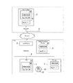
図1は、本実施形態に係るシステムの構成を示すブロック図である。
図1において、PC1、サーバー2は、図2Aで後述するようなハードウェアで構成される。PC1、サーバー2には、OS(Operating System)としてWindows、或いは同等のOSがインストールされている。PC1、サーバー2は、それぞれEthernet(登録商標)で構成されるネットワーク4、8に接続されている。マルチファンクションプリンター3は、カラープリンター、カラーファクシミリ、カラースキャナ等で構成される。なお、マルチファンクションプリンターの代わりに、プリンター、複写機、ファクシミリ、スキャナー、デジタルカメラ等であってもよい。マルチファンクションプリンター3は、以降、MFP3或いはプリンター3と記す場合がある。MFP3は、図2Bで後述するようなハードウェアで構成され、PC1とネットワーク4を介して接続されており、互いに双方向通信が可能である。印刷設定部80は、PC1、サーバー2、プリンター3等に配置される。PCにおける例として、実行形式のファイル(*.EXE)であるアプリケーション50、或いはライブラリ形式のファイル(*.DLL)であるプリンタードライバーソフトウェア50は、印刷設定部80を使用する。なお、図では、App./Drv SW50と記す。
<
[Block diagram showing system configuration]
FIG. 1 is a block diagram showing a configuration of a system according to the present embodiment.
In FIG. 1, the
ネットワーク4は、プリンター3を使用するユーザー(顧客)のオフィスに構築された企業ネットワークである。プリンター3は、このオフィス内でネットワーク4を介してPC1と接続され、共有使用されているMFPである。ネットワーク8は、ウェブサービス・センターに構築されたネットワークである。ネットワーク8に接続されているサーバー2は、Webサーバーの機能を備えるWebサーバー9を備えており、インターネットを介してWebサイトを提供している。PC1に挿入可能なCD−ROM10は、ソフトウェアや電子ファイルが格納されている。印刷設定部80及びアプリケーション或いはプリンタードライバーソフトウェア50は、Webサーバー9やCD−ROM10から配布される。Printer7は、プリンター3と異なるデバイスである。
The network 4 is a corporate network built in the office of a user (customer) who uses the
〔ハードウェア構成を示すブロック図〕
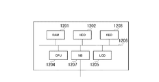
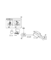
図2は、PC、プリンターのハードウェア構成の一例を示すブロック図である。
図2Aは、PCのハードウェア構成の一例を表すブロック図である。
PC1、サーバー2は、図2Aに示すようなハードウェアで構成されている。図2Aでは、PC1の例で説明する。図2Aに示す通り、PC1は、ランダムアクセスメモリ部(RAM1201)、記憶部であるハードディスクドライブ部(HDD1202)、入力部の一例であるキーボード部(KBD1203)、制御部のCPU1204を含む。更に、PC1は、表示部の一例である表示用ディスプレイ(LCD1205)、通信制御部の一例であるネットワークボード(NB1207)、以上のPC1の構成要素を互いに接続するバス1206を含む。なお、記憶部は、可搬性CD−ROM又は内部据付のROM等であってもよい。印刷設定部80等のアプリケーションや、各モジュール(ソフトウェア)のプログラムは、HDD1202に記憶され、必要に応じてRAM1201に読み出されてCPU1204により実行される。これにより、CPU1204が、印刷設定部80等のアプリケーションや、各モジュール(ソフトウェア)の機能を実現する。
[Block diagram showing hardware configuration]
FIG. 2 is a block diagram illustrating an example of a hardware configuration of a PC and a printer.
FIG. 2A is a block diagram illustrating an example of a hardware configuration of a PC.
The
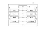
図2Bは、MFPのハードウェア構成の一例を示すブロック図である。
MFP3は、図2Bに示すようなハードウェア構成を持つ。CPU15は、MFP3の中央処理装置として、ROM16に記憶されているプログラムに従って、RAM17、通信部18、記録部19、操作部20、表示部21、読取り部22、ファクシミリ制御部23を制御する。ROM16にはCPU15の制御に従ってMFP3が記録(印刷)処理や、状態をPC1へ伝える処理を行うプログラムが記憶されている。RAM17は、主にPC1から送られて、それを基に記録部19によって印刷される印字データが一時的に記憶される。また、RAM17には、読取り部22で読取られた画像データ、PC1からの印刷ジョブの受信データ等も一時的に記憶される。通信部18にはネットワーク4用の接続ポートの接続ポート等が含まれており、Ethernetや印刷ジョブの通信を制御する。記録部19は、電子写真方式のレーザーユニット、ドラム、各カラートナー、記録紙搬送機構等から構成される記録ユニットと、ASIC等から構成される電気回路と、から構成される。印刷可能なアプリケーション上から印刷操作によって、印刷ジョブがPC1のHDD1202に一時的に格納される。制御用コマンドを含む印字データに変換された印刷ジョブは、ネットワーク4を介してMFP3に送られる。MFP3にて受信された印字データは、記録部19で、記録紙上に印刷される。操作部20は、電源ボタン、リセットボタン等の各種ボタンから構成され、MFP3を操作することができる。表示部21は、タッチパネルの液晶ディスプレイで構成され、MFP3の状態の表示や、各種設定や設定表示、入力等を行うことができる。読取り部22は、カラーイメージセンサや画像処理用のASIC等から構成される電気回路とから構成される。ファクシミリ制御部23は、ファクシミリ用のモデムや通信回路等から構成され、ファクシミリの通信プロトコルに従ってファクシミリの送信や受信を制御する。
CPU15が、ROM16等に記憶されているプログラムを必要に応じてRAM17に読み出し、実行することによって、MFP3の機能等が実現される。
FIG. 2B is a block diagram illustrating an example of a hardware configuration of the MFP.
The
The
〔ソフトウェア構成のブロック図〕
図3は、PCのソフトウェア構成の一例を示すブロック図である。
PC1を例として構成を説明する。アプリケーション或いはプリンタードライバーソフトウェア50は、プリンター3の利用や制御のためにロードされる。印刷ドキュメント70は、プリンター3の印刷に際しスプールされるファイルである。印刷ドキュメント70は、印刷の描画及び設定情報を含んでいる。
印刷設定部80は、印刷設定UI81、制御部85、ワークデータ88からなる。
制御部85は、印刷設定部80の実行を制御する。制御部85は、UI設定を表示する表示制御部86、印刷設定のデータを管理するデータ管理部87のモジュールを持っている。
印刷設定UI81は、ユーザーが印刷設定時に操作するUIである。印刷設定UI81は、制御部85の表示制御部86により実行を制御される。印刷設定UI81は、共通設定UI82、及び個別設定UI83を含んでいる。表示制御部86が共通設定UI82、個別設定UI83をどのように制御して印刷設定を表示するか、また印刷設定のデータとしての管理方法は後述する。
ここで、印刷設定UIは、印刷設定画面、又は設定画面の一例である。共通設定UIは、プリンター3の機種に依存しない共通設定を設定可能な共通設定画面、又はPC1又はサーバー2側の共通印刷設定画面の一例である。また、個別設定UIは、プリンター3の機種に依存する個別設定を設定可能な個別設定画面、又はプリンター3側の個別印刷設定画面の一例である。なお、プリンター3は、画像処理装置の一例である。また、PC1、サーバー2、プリンター3は、情報処理装置の例である。
[Software configuration block diagram]
FIG. 3 is a block diagram illustrating an example of the software configuration of the PC.
The configuration will be described using the
The
The
The
Here, the print setting UI is an example of a print setting screen or a setting screen. The common setting UI is an example of a common setting screen on which common settings independent of the model of the
ワークデータ88は、制御部85が実行時に作成し、参照するデータである。デフォルト共通設定UI(Def.UI#2)89がワークデータ88に紐付けられており、必要に応じて共通設定UI82へロードされ利用される。環境変数90は、ワークデータ88の作成に際して参照される変数である。環境変数90は、印刷設定部80に与えられる変数である。環境変数90は、Type 91、UI#2 92、UI#3 93を含む。Type 91は、実行環境のタイプが記載された変数である。UI#2 92とUI#3 93とは、利用する共通設定UI82、個別設定UI83を指し示したデータである。環境変数90、ワークデータ88がどのようなデータであるかは後述する。
なお、印刷設定部80は、HDD1202と同様にFD、CD−ROM、NB1207のネットワークを経由した媒体に保存されファイルとして追加や更新が可能となっている。これらはOSやそのモジュールを利用するモジュールによってRAM1201にロードされCPU1204に解釈されて実行されるプログラムのモジュールである。
また、環境変数90も、HDD1202と同様にFD、CD−ROM、NB1207のネットワークを経由した媒体に保存されファイルとして追加や更新が可能となっている。
以上、PC1のソフトウェア構成の一例を示すブロック図を説明した。続いて、本システムの代表動作例を示す図を説明する。
The
The
Similarly to the
The block diagram illustrating an example of the software configuration of the
〔本システムの代表動作例〕
図4を用いて、本システムの代表動作例を説明する。
ユーザー6が、PC1を操作し印刷設定して、プリンター3へ印刷するケースである。
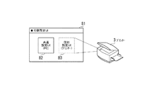
このとき、PC1に表示される印刷設定UI81は、PCの共通設定UI82と、プリンターの個別設定UI83と、を有する。そして、印刷設定UI81による印刷設定結果は、印刷ドキュメント70に設定される。印刷ドキュメント70はプリンター3に送信される。プリンター3は、印刷ドキュメント70の設定に従って印刷出力78を印刷する。
印刷設定においてPC1とプリンター3とが連携しつつ役割を分担する。
以降、この代表動作例を含む本システムの説明を行う。続けて、印刷設定UIがPC1及びプリンター3の設定画面より構成される概要の説明をする。
[Example of typical operation of this system]
A typical operation example of this system will be described with reference to FIG.
In this case, the
At this time, the
In the print setting, the
Hereinafter, the system including this representative operation example will be described. Subsequently, an outline of the print setting UI configured from the setting screens of the
〔印刷設定UIはPC及びプリンターの設定画面より構成される〕
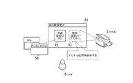
図5を用いて、印刷設定UIがPC1及びプリンター3の設定画面より構成される概要の説明をする。
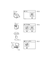
図5Aは、PC1及びプリンター3の設定画面を同時に表示する一例を示す図である。印刷設定UI81では、PCの共通設定UI82と、プリンターの個別設定UI83と、が同時に表示されている。共通設定UI82は、アプリケーション或いはプリンタードライバーソフトウェア50のUI表示のようにPC側で形成されるUIである。個別設定UI83は、PC1で表示されるプリンター3の持つ印刷設定UIである。ユーザー6は、PC側(情報処理装置側)とプリンター側のUIを合わせて操作して印刷設定を行う。
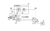
図5Bは、PC及びプリンターのUIの設定結果をドキュメントに設定する一例を示す図である。共通設定UI82は、PC側で形成され表示される(502)。個別設定UI83は、プリンターの持つ設定UIが表示される(503)。印刷設定部80は、これらのUIの設定結果504を印刷ドキュメント70に設定する(505)。プリンター3は、プリンター3のUIである個別設定UI83の設定結果を印刷ドキュメント70経由で受け取る。
以上、印刷設定UIがPC及びプリンターの設定画面より構成されて、設定結果をドキュメントに設定する例を説明した。続いて、本システムのUIの表示がユーザーの使用場所に応じて変化する例を説明する。
[The print settings UI consists of PC and printer settings screens]
With reference to FIG. 5, an outline of the print setting UI configured from the setting screens of the
FIG. 5A is a diagram illustrating an example of displaying the setting screens of the
FIG. 5B is a diagram illustrating an example of setting a UI setting result of a PC and a printer in a document. The
The example in which the print setting UI is configured from the setting screens of the PC and the printer and the setting result is set in the document has been described above. Next, an example will be described in which the UI display of this system changes according to the use location of the user.
〔印刷設定UIの表示がユーザーの使用場所に応じて変化する〕
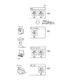
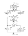
図6は、本システムの印刷設定UIの表示がユーザーの使用場所に応じて変化する一例を説明するための図である。PC1とプリンター3とのUIをユーザーの使用場所に適合するよう連携させる例である。
制御部85は、600の印刷設定UI81に、PCの共通設定UI82とプリンターの個別設定UI83とを合わせて表示する。
一方、制御部85は、WAN側のサーバー2で実行されたとき、共通設定UI82(PC)のみを表示する(601)。通常、サーバー2は、ファイアウォール5の背後にあるプリンター3が特定できないからである。したがって、制御部85は、個別設定UI83(プリンター)を、非表示とする。
また、制御部85は、LAN側のPC1で実行されたとき、前述の通り共通設定UI82(PC)と個別設定UI(プリンター)とを合わせて表示する(602)。通常はPC1からプリンター3が特定できるので、制御部85は、個別設定UI83(プリンター)も表示する。
また、制御部85は、LAN側のプリンター3で実行されたとき、個別設定UI(プリンター)のみを表示する(603)。通常はプリンター3からの、ユーザー6が操作するPC1へのアクセスが難しいからである。
以上、本システムのUIの表示がユーザーの使用場所に応じて変化する例を説明した。次は本システムにおけるPC1のUIとプリンター3のUIの設定項目の分担を説明する。
[Display of print setting UI changes according to user's location]
FIG. 6 is a diagram for explaining an example in which the display of the print setting UI of the present system changes according to the use location of the user. This is an example in which the UIs of the
The
On the other hand, the
In addition, when executed on the LAN-
Further, the
The example in which the UI display of this system changes according to the use location of the user has been described above. Next, sharing of setting items of the UI of the
〔更に印刷設定UIは共通設定、個別設定と対象項目を分担する〕
図7を用いて、本システムのPCのUIとプリンターのUIの設定項目の分担を説明する。
ここまで説明したPC1とプリンター3のUIの配置を維持しつつ、更に本システムは設定対象項目を、共通印刷設定と個別印刷設定に分担する。
図7Aは、本システムのPCのUIとプリンターのUIとの設定項目の分担の概要図で
ある。
印刷設定UI81は、共通設定UI82と個別設定UI83とで構成される。PC側のUIである共通設定UI82は、プリンターに個別でない、印刷に対する共通な設定項目を担当する。プリンター側のUIである個別設定UI83は、プリンターに対して個別の設定項目を担当する。
図7Bは、本システムのPCのUIとプリンターのUIとの設定項目の分担のより具体的な一例を示す図である。
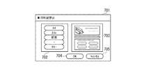
印刷設定UI701において、共通設定UI702と個別設定UI703とが表示されている。共通設定UI702は、PC側のUIであり、プリンターに共通な用紙サイズ、N−Up、両面、カラー等、一般的な設定項目が表示されている。個別設定UI703は、プリンター側のUIであり、プリンターに個別の設定項目が表示されている。この個別設定UI703の設定項目には、共通設定UI702の項目が含まれていてもよい。ユーザーが[OK]ボタン704を押すと、印刷設定が保存される。ユーザーが[キャンセル]ボタン705を押すと印刷設定は保存されない。
[Furthermore, the print setting UI shares common settings, individual settings, and target items]
The sharing of the setting items of the PC UI and printer UI of this system will be described with reference to FIG.
While maintaining the UI arrangement of the
FIG. 7A is a schematic diagram of sharing of setting items between the PC UI and the printer UI of the system.
The
FIG. 7B is a diagram illustrating a more specific example of sharing of setting items between the PC UI and the printer UI of the system.
In the
また、共通設定項目は、[用紙サイズ、用紙の向き、給紙方法、部数、部単位、解像度、カラーモード、N−up、拡大縮小、両面、ステイプル、とじ方向、製本、及び用紙タイプ、ジョブ名]を含む。ここで設定項目における共通設定UI702と個別設定UI703との関係についてステイプルの設定項目を例にとして説明する。共通設定UI702の[ステイプル]の項目は、例えば[ON/OFF]の設定値をとる。共通設定UI702の[ステイプル]が[ON]であれば、例えば印刷物の左上がステイプルされる。対して、あるプリンターの個別設定UI703の[ステイプル]の項目は、例えば[左上/左下/左/右上/右下/右/上/下]と[1ヶ所/2ヶ所]の設定値をとる。個別設定UI703の[ステイプル]は、プリンターに装着されたフィニッシャーの能力にあわせた詳細な設定が行える。このように共通設定UI702と個別設定UI703とが同じ設定項目を含む場合、その設定値は一般的に個別設定UI703の方がより詳細な値をとる。
以上、本システムのPCのUIは共通設定を、プリンターのUIは個別設定を分担する例を説明した。続いて、共通設定及び個別設定の印刷設定データの構成を説明する。
Common setting items are [paper size, paper orientation, paper feeding method, number of copies, copy unit, resolution, color mode, N-up, enlargement / reduction, duplex, staple, binding direction, bookbinding, paper type, job Name]. Here, the relationship between the
Heretofore, an example has been described in which the PC UI of this system shares common settings and the printer UI shares individual settings. Next, the configuration of common setting and individual setting print setting data will be described.
〔印刷設定データもPC及びプリンターに分けて管理される〕
図8を用いて、共通設定及び個別設定の印刷設定データの構成を説明する。UI画面と同様に印刷設定データは、共通設定と個別設定に区分される。
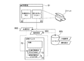
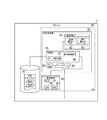
図8Aは、PC及びプリンターの印刷設定データの構成概要図である。印刷設定データは、印刷設定UIの分担と同様、共通設定802と個別設定803とから構成される。前述のとおり、印刷設定UI81は、共通設定UI82(PC)と、個別設定UI83(プリンター)とから構成される。この共通設定UI82は、印刷設定データとして共通設定802を出力する。また、個別設定UI83は、印刷設定データとして個別設定803を出力する。この共通設定802及び個別設定803は、レジストリー805へ保存される。
印刷ドキュメント70は、共通印刷設定72と個別印刷設定73とを含む構造をとる。前述の共通設定802は、共通印刷設定72としてPrintTicket形式で印刷ドキュメント70に設定される。前述の個別設定803は、個別印刷設定73として個別設定UI83(プリンター)からエクスポートされたデータとして印刷ドキュメント70に設定される。なお、PrintTicket(プリントチケット)とは一般的に印刷設定や属性を保存するデータでありXML書式で記述されることが多いが、より具体的な例については後述する。
[Print setting data is also managed separately for PC and printer]
The configuration of common setting and individual setting print setting data will be described with reference to FIG. Similar to the UI screen, the print setting data is divided into common settings and individual settings.
FIG. 8A is a schematic configuration diagram of print setting data of a PC and a printer. The print setting data includes a
The
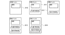
図8Bは、印刷ドキュメントへの共通印刷設定と個別印刷設定との設定パターンの一例を示す図である。共通印刷設定72及び個別印刷設定73は、必ず印刷ドキュメントに格納されるわけではない。また、共通印刷設定72は基本的に1つである。個別印刷設定73は、プリンター毎の設定であるから複数、印刷ドキュメントに格納されてよい。例えば、印刷設定なし(810)、共通印刷設定72だけ(811)、個別印刷設定73だけ(812)のパターンや、共通印刷設定72と個別印刷設定73とが各1つある(813)、或いは個別印刷設定73が複数ある(814)等のパターンがある。
以上、共通設定及び個別設定の印刷設定データの構成を説明した。続いて印刷設定データやワークデータのより具体的な例を説明する。
FIG. 8B is a diagram illustrating an example of a setting pattern for common print settings and individual print settings for a print document. The common print setting 72 and the individual print setting 73 are not necessarily stored in the print document. Further, there is basically one common print setting 72. Since the
The configuration of the print settings data for common settings and individual settings has been described above. Next, more specific examples of print setting data and work data will be described.
〔データ形式の具体例−印刷設定、ワークデータ〕
図9を用いて、印刷設定データやワークデータのより具体的な例を説明する。
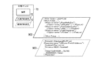
図9の説明の前に、XPS(XML Paper Specification)ドキュメントについて簡単に説明する。XPSドキュメントは、ページの内容をXML形式で記述しており、実際に表示又は印刷される内容を含んでいる。また、XPSドキュメントは、使用されるフォントや画像等のリソースも含んでいる。また、XPSドキュメントは、印刷設定をPrintTicket(PT)で持つことができる。PTは、XPSドキュメントを印刷する際の印刷設定をXML形式で記述したものである。続く図9Aにおいて印刷ドキュメント70は、XPSドキュメント、或いは同様フォーマットのドキュメントであるとして説明を行う。
図9Aは、共通印刷設定72及び個別印刷設定73のより具体的な例を示す図である。共通印刷設定72は、XMLファイル902の形で印刷ドキュメント70に格納される。XMLファイル902は、Job_PT.xmlの名称のXMLファイルである。前述の共通印刷設定項目の用紙サイズ、用紙の向き、解像度等が次のPrintTicket形式に記載されている。
<f:PrintTicket ... > ・・・ </f:PrintTicket>
個別印刷設定73は、ファイル903の形で印刷ドキュメント70に格納される。903は、%HardwareID%_PT.xmlのファイル名の名称のXMLファイルである。%HardwareID%は、プリンター3に固有であるハードウェアID文字列であり、これをファイル名に用いている。プリンターの設定UIの名称、更新日時等ファイル管理用の情報に続き、プリンターの印刷設定データは、次のようなBOLB形式で記載されている。
<Value>QwBhAG4A......(BLOB)......AAABAAAA</Value>
なお、プリンターの印刷設定データのエクスポート、ストア、インポートをXMLファイルで行う例としてBLOB形式で説明している。個別印刷設定73は、プリンター3がハンドリングするデータであるので、他の形式を選択してもよい。個別印刷設定73もPrintTicket形式にすることもできる。この際は、個別印刷設定73への固有namespaceの追加によって、個別印刷設定73と共通印刷設定72とを分けることができる。
[Specific examples of data format-print settings, work data]
More specific examples of the print setting data and work data will be described with reference to FIG.
Prior to the description of FIG. 9, an XPS (XML Paper Specification) document will be briefly described. The XPS document describes the contents of a page in the XML format, and includes contents that are actually displayed or printed. The XPS document also includes resources such as fonts and images used. In addition, an XPS document can have print settings in PrintTicket (PT). The PT describes the print settings for printing the XPS document in the XML format. In FIG. 9A, the
FIG. 9A is a diagram illustrating a more specific example of the common print setting 72 and the individual print setting 73. The common print setting 72 is stored in the
<F: PrintTicket. . . ></ F: PrintTicket>
The individual print setting 73 is stored in the
<Value> QwBhAG4A. . . . . . (BLOB). . . . . . AAABAAAA </ Value>
Note that the BLOB format is used as an example of exporting, storing, and importing print setting data of a printer as an XML file. Since the individual print setting 73 is data handled by the
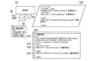
図9Bは、環境変数90とワークデータ88とのより具体的な一例を示す図である。制御部85は、環境変数90を参照し、ワークデータ88を作成する。環境変数90のより具体的な一例が930である。Type 931は、実行環境のタイプが記載された変数である。Type 931は、PC、Printerの値をとり、制御部85が、共通設定UI82(PC)と個別設定UI83(プリンター)との表示を制御する際に参照される。このType 931は、サービスのエンドポイントの指定としてもよい。この場合、制御部85は、サービスのエンドポイントならPrinterであると判断することもできる。UI#2 932とUI#3 933とは、利用する共通設定UI82、個別設定UI83を指し示したデータである。制御部85は、UI#2 932とUI#3 933とのURI表記からローカル、或いはリモートといったUIの位置が区別できる。またENV935は、実行環境のプラットフォームやCPU情報も変数となっている。このENV935は、Type 931が変数に設定されていないとき、実行環境の判定に使用される。Platform変数は、JAVA(登録商標)の変数でWin32等の値をとる。User−Agentヘッダは、HTTP変数であり、プリンター環境に固有の文字列を付与しておくと判定に利用することができる。ワークデータ88のより具体的な例が920である。920のデータ形式は、環境変数930とほぼ同等である。制御部85は、デフォルトのワークデータをロードし、環境変数930のType931、UI#2 932、UI#3 933等を参照しながらワークデータ920を構築する。
以上、印刷設定データやワークデータのより具体的な一例を説明した。続けて、印刷設定データのデータフローを説明する。
FIG. 9B is a diagram showing a more specific example of the
The specific examples of the print setting data and work data have been described above. Next, the data flow of print setting data will be described.
〔印刷設定データのデータフロー−環境を移動する印刷データ〕
図10を用い、印刷設定データのデータフローを説明する。
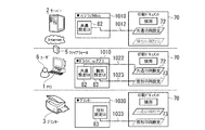
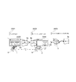
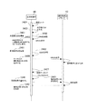
図10Aは、印刷ドキュメント70が環境間を移動しつつ、印刷設定が順次設定される一例を示す図である。まずサーバー2では、印刷設定UI1010には共通設定UI82が表示される。この共通設定UI82の操作結果は、1020のように印刷ドキュメント70の共通印刷設定72に反映される。次にPC1では、印刷設定UI1020には共通設定UI82と個別設定UI83とが表示される。共通設定UI82の操作結果は、1022のように印刷ドキュメント70の共通印刷設定72に反映される。個別設定UI83の操作結果は、1023のように印刷ドキュメント70の個別印刷設定73に反映される。最後にプリンター3では、印刷設定UI1030には個別設定UI83が表示される。個別設定UI83の操作結果は、1033のように印刷ドキュメント70の個別印刷設定73に反映される。印刷ドキュメント70は、サーバー2、PC1、プリンター3を移動する。共通印刷設定72、個別印刷設定73の印刷設定は、印刷ドキュメント70と共に移動する。そしてユーザーは、各環境に適切な印刷設定UI81上の共通設定UI82や個別設定UI83を操作し印刷設定を行うことができる。
[Data flow of print setting data-Print data moving through the environment]
The data flow of print setting data will be described with reference to FIG.
FIG. 10A is a diagram illustrating an example in which print settings are sequentially set while the
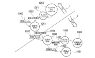
図10Bは、PC1からプリンター3への個別印刷設定73のデータフローを説明するための図である。個別設定UI83(プリンター)からエクスポートされた個別設定データは、印刷ドキュメント70に個別印刷設定73として格納されてプリンターに戻り、印刷設定データとしてインポートされる。この一連の印刷設定フローで、PC側で個別印刷設定73を解釈する処理をしていない。
1041側が、PC1上のデータのフローである。
処理1050では、PC1の制御部85は、個別設定UI83(プリンター)から印刷設定をエクスポートする。
処理1051では、PC1の制御部85は、その印刷設定をBLOBエンコードする。
データ1052の個別印刷設定73が出力される。
データ1060の印刷ドキュメント70が入力される。
すると、処理1061では、PC1の制御部85は、印刷ドキュメント70と個別印刷設定73とを入力として、設定の格納を行う。
データ1070の印刷ドキュメント70にデータ1071の個別印刷設定73が格納される。
印刷ドキュメント70に個別印刷設定73が格納され、プリンター3へ送信される。
1043側が、プリンター3上のデータのフローである。
処理1080では、プリンター3の制御部85は、個別印刷設定73が格納された印刷ドキュメント70を入力として、設定の取出を行う。
データ1081の個別印刷設定73が取り出される。
処理1082では、プリンター3の制御部85は、個別印刷設定73をBLOBデコードする。
処理1083では、プリンター3の制御部85は、その印刷設定を適用する。
データ1090の印刷ドキュメント70を入力として、処理1091では、プリンター3の制御部85は、印刷出力する。その印刷設定は処理1083で適用されている。
以上、印刷設定データのデータフローを説明した。続いて、本システムのフローを説明する。
FIG. 10B is a diagram for explaining the data flow of the individual print setting 73 from the
The 1041 side is a data flow on the
In
In
The individual print setting 73 of the
A
Then, in
The individual print setting 73 of the
The individual print setting 73 is stored in the
The 1043 side is the data flow on the
In
The individual print setting 73 of the
In
In
Using the
The data flow of the print setting data has been described above. Next, the flow of this system will be described.
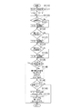
〔制御部のワークデータ形成のフローチャート〕
図11は、制御部85のワークデータ形成のフローチャートである。
ステップS1110から、制御部85は、ワークデータ作成のフローを開始する。
ステップS1111では、制御部85は、デフォルトワークデータをロードする。
ステップS1120では、制御部85は、Type環境変数が有ればステップS1121へ進み、無ければステップS1122へ進む。
ステップS1121では、制御部85は、ワークデータのType変数を更新する。
ステップS1122では、制御部85は、第二のUI(UI#2)環境変数が有れば(存在すれば)ステップS1123へ進み、無ければ(存在しなければ)ステップS1124へ進む。
ステップS1123では、制御部85は、ワークデータのUI#2変数を更新する。
ステップS1124では、制御部85は、第三のUI(UI#3)環境変数が有ればステップS1125に進み、無ければステップS1130へ進む。
ステップS1125では、制御部85は、ワークデータのUI#3変数を更新する。
ステップS1130では、制御部85は、ここまでの3変数が取得できたなら図11に示す処理を終了し、取得でき無ければステップS1140へ進む。
ステップS1140では、制御部85は、実行環境の変数(Platform、CPU、Lang、Use−Agent)を入手する。
ステップS1142では、制御部85は、プリンターの実行環境の変数パターンとマッチしていれば、ステップS1142へ進み、マッチしなければ図11に示す処理を終了する。
ステップS1143では、制御部85は、ワークデータのTypeをPrinterにする。
ステップS1144では、制御部85は、ワークデータの第2のUI(UI#2)をブランクにする。
図11のフローの補足説明をする。
ここでワークデータが作成されると、PCかPrinterかのタイプが決まる。以降のTypeに応じたフローチャートが有った場合、制御部85のワークデータ参照による処理として扱い、重複した説明は省略する。
このときに、デフォルトのTypeはPCとした。Type変数がなく、実行環境を判定して、Printerと判定されなければPCとなる(ステップS1124のNo)。この場合もPCタイプであるから少なくとも共通印刷設定は有効となる。
[Flow chart of work data formation of control unit]
FIG. 11 is a flowchart of work data formation by the
From step S1110, the
In step S1111, the
In step S1120, if there is a Type environment variable, the
In step S1121, the
In step S1122, the
In step S1123, the
In step S1124, if there is a third UI (UI # 3) environment variable, the
In step S1125, the
In step S1130, the
In step S1140, the
In step S1142, the
In step S1143, the
In step S1144, the
A supplementary explanation of the flow of FIG. 11 will be given.
When the work data is created here, the type of PC or Printer is determined. When there is a flowchart corresponding to the subsequent Type, it is handled as a process by referring to the work data of the
At this time, the default type was PC. If there is no Type variable, the execution environment is determined, and if it is not determined to be Printer, the PC is set (No in step S1124). Also in this case, since it is a PC type, at least the common print setting is valid.
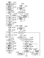
〔制御部の印刷設定UI生成のフローチャート〕
図12は、制御部の印刷設定UI生成のフローチャートである。
ステップS1211から、制御部85は、設定の読み出しを開始する。
ステップS1212では、制御部85は、共通設定を読み出す。
ステップS1213では、制御部85は、個別設定を読み出す。
ステップS1214では、制御部85は、前設定が無いならステップS1214へ進み、前設定が有るならステップS1220へ進む。
ステップS1215では、制御部85は、デフォルト設定をロードする。
ステップS1220から、制御部85は、UI表示を開始する。
ステップS1221では、制御部85は、表示をロックする。
ステップS1222では、制御部85は、バックグラウンドへ移行する。
ステップS1223では、制御部85は、印刷設定UI(第一)を表示する。
ステップS1224では、制御部85は、フロー番号(2、共通)をコールする。
ステップS1225では、制御部85は、フロー番号(3、個別)をコールする。
ステップS1226では、制御部85は、フォアグラウンドへ移行する。
ステップS1227では、制御部85は、表示をアンロックする。
ステップS1231では、制御部85は、OKボタンが押されたならステップS1240へ進み、押されて無いならステップS1230へ戻る。
ステップS1240から、制御部85は、設定の書き出しを開始する。
ステップS1241では、制御部85は、共通設定を書き出す。
ステップS1242では、制御部85は、個別設定を書き出す。
ステップS1243では、制御部85は、個別設定をBLOBエンコードする。
[Flowchart for generating print setting UI of control unit]
FIG. 12 is a flowchart of print setting UI generation by the control unit.
From step S1211, the
In step S1212, the
In step S1213, the
In step S1214, the
In step S1215, the
From step S1220, the
In step S1221, the
In step S1222, the
In step S1223, the
In step S1224, the
In step S1225, the
In step S1226, the
In step S1227, the
In step S1231, the
From step S1240,
In step S1241, the
In step S1242, the
In step S1243, the
ステップS1250から、フロー番号(2、共通)である。
ステップS1251から、制御部85は、共通設定UI82の構築を開始する。
ステップS1252では、制御部85は、ワークデータに第二のUI変数(UI#2)が有ればステップS1253へ進み、無ければステップS1254へ進む。
ステップS1253では、制御部85は、共通設定UI82を表示する。
ステップS1254では、制御部85は、共通設定UI82を非表示にする。
ステップS1250から、フロー番号(3、個別)である。
ステップS1261から、制御部85は、個別設定UI83を構築する
ステップS1262では、制御部85は、ワークデータに第三のUI変数(UI#3)が有ればステップS1263へ進み、無ければステップS1282へ進む。
ステップS1263では、制御部85は、第三のUI変数(UI#3)がローカルを指しているか確認し、ローカルならステップS1280へ進み、ローカルで無ければステップS1264へ進む。
ステップS1280では、制御部85は、ローカルの個別設定UI83(ローカル)を表示する。ここで、ローカルの個別設定UIとは、例えば、自装置の記憶部等に記憶されているローカルな個別設定UIのことをいう。
ステップS1264では、制御部85は、リクエストデータを作成する。
ステップS1265では、制御部85は、リクエストをプリンター3に送信する。
ステップS1266では、制御部85は、プリンター3と通信可(通信可能)か判定し、通信可ならステップS1267へ進み、通信不可(通信不可能)ならステップS1282へ進む。
ステップS1267では、制御部85は、レスポンスを受信する。
ステップS1268では、制御部85は、レスポンスを確認して可ならステップS1281へ進み、不可ならステップS1282へ進む。
ステップS1281では、制御部85は、リモートの個別設定UI83(リモート)を表示する。ここで、リモートの個別設定UIとは、例えば、ネットワークを介して接続されたプリンター3のUIそのものことをいう。
ステップS1282では、制御部85は、個別設定UI83を非表示にする。
ステップS1283では、制御部85は、通信できなかったワークデータのUI#3をブランクにする。
図12のフローチャートを補うため、続けて印刷設定UIのPC1とプリンター3とのシーケンス図を説明する。
From step S1250, it is a flow number (2, common).
From step S1251, the
In step S1252, if the work data includes the second UI variable (UI # 2), the
In step S1253, the
In step S1254, the
From step S1250, it is a flow number (3, individual).
From step S1261, the
In step S1263, the
In step S1280, the
In step S1264, the
In step S1265, the
In step S1266, the
In step S1267, the
In step S1268, the
In step S1281, the
In step S1282, the
In step S1283,
In order to supplement the flowchart of FIG. 12, a sequence diagram of the
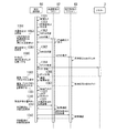
〔印刷設定UIのPCとプリンターのシーケンス図〕
図13は、印刷設定UIのPCとプリンターのシーケンス図である。
シーケンスの概要は、共通設定UI82(PC1)と個別設定UI83(プリンター3)とを表示して、UI設定が終われば、それぞれの設定結果の書き出す流れとなる。ここでPC1において個別設定UI83(プリンター)を表示するとき、制御部85は、プリンター3へUIを要求して、プリンター3から応答を得る。
ステップS1321では、制御部85の表示制御部86は、画面をロックする。
ステップS1323では、制御部85の表示制御部86は、印刷設定UI81を表示する。
ステップS1351から、制御部85の表示制御部86は、共通設定UI82の構築を開始する。
ステップS1352では、制御部85の表示制御部86は、ワークデータのUI#2を確認する。
ステップS1353では、制御部85の表示制御部86は、UI#2が有れば共通設定UI82を表示する。
ステップS1361から、制御部85の表示制御部86は、個別設定UI83の構築を開始する。
ステップS1362では、制御部85の表示制御部86は、ワークデータのUI#3を確認する。
[Print Settings UI PC and Printer Sequence Diagram]
FIG. 13 is a sequence diagram of the PC and printer of the print setting UI.
As an overview of the sequence, the common setting UI 82 (PC1) and the individual setting UI 83 (printer 3) are displayed, and when the UI setting is completed, the setting results are written. Here, when displaying the individual setting UI 83 (printer) on the
In step S1321, the
In step S1323, the
From step S1351, the
In step S1352, the
In step S1353, the
From step S 1361, the
In step S1362, the
UI#3がローカルを指している場合、ステップS1380では、制御部85の表示制御部86は、個別設定UI83(ローカル)を表示する。
UI#3がローカルを指していない(リモートを指している)場合、ステップS1364では、制御部85の表示制御部86は、リクエストデータを作成する。
ステップS1365では、制御部85の表示制御部86は、プリンター3へリクエストを送信する。
ステップS1367では、制御部85の表示制御部86は、プリンター3からレスポンスを受信する。
UI#3がリモートを指し、プリンター3に通信、アクセスできた場合、ステップS1381では、制御部85の表示制御部86は、個別設定UI83(リモート)を表示する。
なお、本実施形態の一例では、個別設定UI83を表示させるためプリンター3のリモートUI機能を利用する。リモートUI機能は、Webブラウザからネットワークを経由して、プリンター3にアクセスし、プリンター3の状況確認、操作、各種設定ができる機能である。そのため、プリンター3にはリモートUIを使用するためのWebサーバーが内蔵されている。このWebサーバーが制御部85の表示制御部86からの要求された個別設定UIのページを送信することで、制御部85の表示制御部86は個別設定UI83を表示させる。
プリンター3に通信、アクセスできなかった場合等、ステップS1382では、制御部85の表示制御部86は、個別設定UI83を非表示にする。
ステップS1327では、制御部85の表示制御部86は、表示をアンロックする。
ステップS1340から、制御部85の表示制御部86は、設定結果を書き出す。
ステップS1342では、制御部85の表示制御部86は、共通設定UI82の設定を要求する。
ステップS1343では、制御部85の表示制御部86は、個別設定UI83の設定を要求する。
印刷設定UIのPC1とプリンター3とのシーケンス図を説明した。続けて、PC1の印刷ドキュメントへの印刷設定データの格納のフローを説明する。
When
If
In step S1365, the
In step S <b> 1367, the
When
In the example of the present embodiment, the remote UI function of the
In step S1382, the
In step S1327, the
From step S1340, the
In step S1342, the
In step S 1343, the
The sequence diagram between the
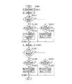
〔PCの印刷ドキュメントへの印刷設定データ格納フローチャート〕
図14は、PC1の印刷ドキュメント70への印刷設定データの格納のフローチャートである。
制御部85は、印刷ドキュメント70内の印刷設定に加え、UIの設定結果の有無から動作を変える。また制御部85は、個別設定に関して対象プリンターに応じた制御を行う。
更に、制御部85は、共通印刷設定72と個別印刷設定73との扱いが異なる。制御部85は、共通印刷設定72に関しては、各所で共有されるため設定をマージ更新するが、
個別印刷設定73に関しては、プリンター個別であるので設定を置き換える。
ステップS1401から、制御部85は、設定の格納を開始する。
ステップS1410から、制御部85は、共通印刷設定72の格納を開始する。
ステップS1411では、制御部85は、印刷ドキュメント70に共通印刷設定72が有ればステップS1412へ進み、無ければステップS1414へ進む。
ステップS1412では、制御部85は、共通設定UI82の設定結果が有ればステップS1413へ進み、無ければステップS1418へ進む。
ステップS1413では、制御部85は、印刷ドキュメント70の共通印刷設定72と共通設定UI82との設定結果をマージしてドキュメントの共通印刷設定72を更新する。
ステップS1414では、制御部85は、共通設定UI82の設定結果が有ればステップS1415に進み、無ければステップS1418へ進む。
ステップS1415では、制御部85は、共通設定UI82の設定結果を印刷ドキュメント70に共通印刷設定72として入れる。
[Flowchart for storing print setting data in PC print document]
FIG. 14 is a flowchart of storing print setting data in the
The
Further, the
The individual print setting 73 is replaced because it is individual printer.
From step S1401, the
From step S1410, the
In step S1411, the
In step S1412, the
In step S1413, the
In step S1414, if there is a setting result of the
In step S <b> 1415, the
ステップS1420から、制御部85は、個別印刷設定73の格納を開始する。
ステップS1421では、制御部85は、印刷ドキュメント70に同デバイスの個別印刷設定73が有ればステップS1422へ進み、無ければステップS1424へ進む。
ステップS1422では、制御部85は、個別設定UI83の設定結果が有ればステップS1423へ進み、無ければステップS1428へ進む。
ステップS1423では、制御部85は、印刷ドキュメント70の個別印刷設定73を個別設定UI83の設定結果で置き換える。
ステップS1424では、制御部85は、個別設定UI83の設定結果が有ればステップS1425へ進み、無ければステップS1425へ進む。
ステップS1425では、制御部85は、印刷ドキュメント70へ個別設定UI83の設定結果を個別印刷設定73として入れる。
なお、個別設定UI83の設定結果は、BLOBエンコード済みとしてチャートを記載した。以上、PC1の印刷ドキュメント70への印刷設定データの格納のフローチャートを説明した。
ここまでのフローチャートに係るプログラムは、PC1であればHDD1202に記憶されており、RAM1201に読み出され、CPU1204により実行される。ここまでのフローチャートに係るプログラムは、プリンター3であればROM16に記憶されており、RAM17に読み出され、CPU15によって実行される。また、NB1207や通信部18を介した外部と通信して受信したプログラムやデータはCPU1204やCPU15で実行される。
以上、本実施形態の処理を説明した。
From step S1420, the
In step S1421, the
In step S1422, if there is a setting result of the
In step S <b> 1423, the
In step S1424, the
In step S 1425, the
The setting result of the
The program according to the flowchart so far is stored in the
The processing of this embodiment has been described above.
〔本実施形態の効果の説明〕
上述したように、従来のWAN環境における印刷設定操作には問題があった。即ち、出力プリンターが不定となる場合があるが、そのプリンター不定環境下でもユーザーに一定の印刷設定操作を提供する必要があった。またユーザーは実際出力するプリンターのフル機能を利用したいと考えていた。
問題解決のため、本実施形態の印刷設定UIは、PC1とプリンター3とがネットワーク接続されており、印刷設定UIを有する印刷制御方法において、印刷設定UIは、共通設定UIと個別設定UIとから構成される。共通設定UIは、コンピュータ側の印刷設定UIである。個別設定UIは、プリンター側の印刷設定UIである。
また、本実施の形態の印刷設定UIは、ユーザーの使用場所に応じて表示が制御される。例えば、上述した図6に示したように、制御部85(又は表示制御部86)は、サーバー2で動作している場合は、共通設定UIを表示し、PC1で動作している場合は、共通設定UIと、個別設定UIと、を表示する。また、制御部85(又は表示制御部86)は、プリンター3で動作している場合は、個別設定UIを表示する。
以上、本実施形態によれば、印刷設定においてユーザーは、出力プリンターの不定・確定状態に関わらず、適正な印刷設定操作が行える。
また、ユーザーは、出力プリンターが不定な場合も、一定の操作性を得られる。
そして、ユーザーは、出力プリンターが確定すると、出力プリンターのフル機能を利用できる。
[Explanation of effects of this embodiment]
As described above, there is a problem in the print setting operation in the conventional WAN environment. That is, the output printer may be indefinite, but it is necessary to provide a user with a certain print setting operation even in the printer indefinite environment. The user also wanted to use the full function of the printer that actually outputs.
In order to solve the problem, the print setting UI of the present embodiment is such that the
Further, the display of the print setting UI according to the present embodiment is controlled according to the use location of the user. For example, as shown in FIG. 6 described above, the control unit 85 (or the display control unit 86) displays the common setting UI when operating on the
As described above, according to the present embodiment, in print settings, the user can perform an appropriate print setting operation regardless of the undefined / determined state of the output printer.
Further, the user can obtain a certain operability even when the output printer is indefinite.
When the user determines the output printer, the user can use the full function of the output printer.
本実施形態による操作性、適応性、即時性、設置性の向上効果を説明する。
共通設定UI82と共通印刷設定72とにより、プリンターに応じた設定が必須とならないため、ユーザーは均一な操作性が得られる。また、本システムにプリンターを接続すれば共通設定UI82で設定して印刷ができるようになる。
個別設定UI83や個別印刷設定73により、機種固有の設定ができるため、出力プリンターのフル機能を利用できる。
使用場所に応じた印刷設定UI81における共通設定UI82と個別設定UI83との表示制御により、プリンターが確定した状態で出力プリンター固有の設定がされるので、ユーザーは適切に設定付与でき再設定操作数も抑制される。
共通印刷設定72と個別印刷設定73とのデータが分かれており、印刷ドキュメント70と共に使用場所を移動して順次設定ができるので、複数のプリンター利用や出力プリンター変更への追従性も高くなっている。
プリンター3に固有な個別設定UI83や個別印刷設定73がアプリケーション或いはプリンタードライバーソフトウェア50と分けられているため、PC側のソフトウェアを再インストールしなくとも、ユーザーは将来のプリンターが利用できる。また、ベンダーはPC側のソフトウェアをプリンターのリリース毎に開発して頒布する必要がない。
以上、本実施形態の効果を説明した。続いて、本システム構成の配置を一部変更したときの動作例を説明する。
The improvement effect of the operativity, adaptability, immediacy, and installation property by this embodiment is demonstrated.
Since the
Since the settings specific to the model can be set by the
By the display control of the
Since the data of the common print setting 72 and the individual print setting 73 are separated and can be sequentially set by moving the use place together with the
Since the
The effects of the present embodiment have been described above. Next, an operation example when the arrangement of the system configuration is partially changed will be described.
〔システム構成の配置を変更した例〕
図15は、システム構成を一部変更した場合の動作例を説明するための図である。
図15を用いて、図6で示したシステム構成のプリンター3の位置を変更したときのシステム動作の変化の一例を説明する。
図15のシステム構成では、図6で説明したシステム構成から、プリンター3をサーバー2の側に変更する。サーバー2のLAN側にプリンター3を設置する。Webの印刷サービス・センターにプリンター3が設置されている例となる。
印刷設定UI81では、共通設定UI82(PC)と個別設定UI83(プリンター)とが合わせて表示される。プリンター3で印刷設定部80が実行されたとき、印刷設定UI81には、個別設定UI83(プリンター)のみが表示される(1613)。これは、実施形態1の表示と同様である。
サーバー2で印刷設定部80が実行されたとき、印刷設定UI81には、共通設定UI82(PC)と個別設定UI83(プリンター)とが合わせて表示される(1612)。サーバー2からプリンター3が特定できるからである。
PC1で印刷設定部80が実行されたとき、印刷設定UI81には、共通設定UI82(PC)が表示される。PC1からはファイアウォール5の背後にあるプリンター3が特定できないことが理由である。
図15では、プリンター3の位置変更によりサーバー2とPC1との印刷設定UIが変化する例を示した。本実施形態で示されるネットワーク構成の場合、ユーザー6は、サーバー2のWebサービスを使用するとき、個別印刷設定も行える。
以上の説明のようにプリンター3の位置変更により表示結果は変化する。しかし、処理は図6の場合と同じである。図6の場合においても、印刷設定部80等は、プリンター3との通信等から表示するUIを判別して画面を制御し、PC1とサーバー2といったPC環境間区分からは画面制御をしない。図15を用いて、PC環境間判別をしない意味を説明した。ここまで、PC1のPC環境を主体とした説明した。ここからは、プリンター3を主体とする説明をする。
[Example of changing the system configuration]
FIG. 15 is a diagram for explaining an operation example when the system configuration is partially changed.
An example of a change in system operation when the position of the
In the system configuration of FIG. 15, the
In the
When the
When the
FIG. 15 shows an example in which the print setting UI between the
As described above, the display result is changed by changing the position of the
[プリンターのソフトウェアのブロック図]
図16は、プリンターのソフトウェア構成の一例を示すブロック図である。
ソフトウェア50は、プリンター3の動作や制御のためにロードされる。印刷ドキュメント70は、プリンター3の印刷に際して受信しスプールされるファイルである。印刷ドキュメント70は、印刷の描画及び設定情報を含んでいる。
他は図3で説明したPC1のソフトウェア構成の一例を示すブロック図と同様である。
以上、プリンター3のソフトウェア構成の一例を示すブロック図を説明した。続いて、本システムのプリンター3の代表動作例を示す図を説明する。
[Block diagram of printer software]
FIG. 16 is a block diagram illustrating an example of a software configuration of the printer.
The
Others are the same as the block diagram showing an example of the software configuration of the
The block diagram showing an example of the software configuration of the
[プリンターの代表動作例]
図17は、本システムのプリンターの印刷設定動作例を示す図である。
初めに2201にて、ユーザー6は、PC1上で印刷設定する。
ユーザー6が、PC1に表示される印刷設定UI2205の個別設定UI83でプリンターのRUI(Remote UI)を使用して印刷設定する。印刷設定は、印刷ドキュメント70に格納されプリンター3へ送られる。
次に2202にて、ユーザー6は、プリンター3上で印刷設定する。
ユーザー6は、プリンター3に表示される印刷設定UI2206の個別設定UI83でプリンターのLUI(Local UI)を使用して印刷設定する。印刷設定UI2206は、PC1での設定が反映されて表示されている。ユーザー6は、印刷設定の一部を更新して印刷を指示する。
最後に2203で、プリンター3は印刷出力78を行う。この印刷出力78の印刷設定は、共通設定及び2201と2202とにおける設定結果が反映されている。
以上、本システムのプリンター3の代表動作例を説明した。続いて、プリンター3を中心として本システムの構成を説明する。
[Example of printer operation]
FIG. 17 is a diagram illustrating an example of the print setting operation of the printer of this system.
First, at 2201, the
The
Next, at 2202, the
The
Finally, in 2203, the
The representative operation example of the
[プリンターはPCとプリンターとに設定画面を表示する]
図18は、本システムでプリンターがPCとプリンターに設定画面を表示する一例を示す図である。
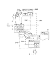
ユーザー6は、PC1上で印刷設定する。PC1に表示される印刷設定UI2300の個別印刷設定は、プリンター3のRUI(2301)である。RUIの印刷設定(2302)は、印刷ドキュメント70の個別印刷設定73に格納されてプリンター3へ送信される。
プリンター3は、印刷ドキュメント70を受信する。ユーザー6は、プリンター3上で印刷設定する。プリンター3に表示される印刷設定UI2310の個別印刷設定は、プリンター3のLUI(2311)である。プリンター3は、印刷ドキュメント70の個別印刷設定73を読み出しLUIを表示し、設定結果を個別印刷設定73へ書き戻す(2312)。
PC1上、プリンター3上での印刷設定結果が印刷出力78へ反映される。
前述の図4では、PC1上の印刷設定UIが、PC1とプリンター3とが連携と役割分担してUI表示する例を説明した。
この図18では、プリンター3が、2つの印刷設定UI(RUI、LUI)を連携させ、印刷設定の表示と編集とを行う例を説明した。
[Printer displays setting screen on PC and printer]
FIG. 18 is a diagram illustrating an example in which the printer displays a setting screen on the PC and the printer in this system.
The
The
The print setting results on the
In the above-described FIG. 4, the example has been described in which the print setting UI on the
FIG. 18 illustrates an example in which the
[プリンター上の印刷設定UIシーケンス]
図19は、プリンターの印刷設定UIのシーケンス図である。
シーケンスの概要は、プリンター3上では共通設定UI82(PC1)を表示せず、ローカルの個別設定UI83(プリンター3)を表示する流れになる。なお、前述した図13の印刷設定UIのPCとプリンターとのシーケンス図から、踏まれない手順を省略した図に相当する。
ステップS2421では、制御部85の表示制御部86は、画面をロックする。
ステップS2423では、制御部85の表示制御部86は、印刷設定UI81を表示する。
ステップS2451から、制御部85の表示制御部86は、共通設定UI82の構築を開始する。
ステップS2452では、制御部85の表示制御部86は、ワークデータのUI#2を確認する。
ステップS2453では、制御部85の表示制御部86は、UI#2が無いので共通設定UI82は非表示にする。
ステップS2461から、制御部85の表示制御部86は、個別設定UI83の構築を開始する。
ステップS2462では、制御部85の表示制御部86は、ワークデータのUI#3を確認する。
UI#3がローカルを指している場合、ステップS2480では、制御部85の表示制御部86は、個別設定UI83(ローカル)を表示する。
ステップS2427では、制御部85の表示制御部86は、表示をアンロックする。
ステップS2431では、印刷設定UI81のOKボタンが押される。
ステップS1240から、制御部85の表示制御部86は、設定結果を書き出す。
ステップS1242では、制御部85の表示制御部86は、個別設定UI83の設定を要求する。
プリンター3上の印刷設定UIの表示シーケンスを説明した。続けて、プリンター3が印刷設定UIにロードする印刷設定データの判別について説明する。
[Print Setting UI Sequence on Printer]
FIG. 19 is a sequence diagram of the print setting UI of the printer.
The outline of the sequence is to display the local individual setting UI 83 (printer 3) without displaying the common setting UI 82 (PC 1) on the
In step S2421, the
In step S2423, the
From step S2451, the
In step S2452, the
In step S2453, the
From step S2461, the
In step S2462, the
When
In step S2427, the
In step S2431, the OK button of the
From step S1240, the
In step S1242, the
The display sequence of the print setting UI on the
[プリンターは、読み出す個別印刷設定を判別する]
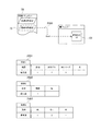
図20は、プリンターの印刷ドキュメントからの個別印刷設定データの読み出し動作例を説明するための図である。
プリンター3は、印刷ドキュメント70内の個別印刷設定73を読み出し(2500)、印刷設定UIの個別設定UI83に表示する。この読み出し(2500)の際に、プリンター3は、自機に適正な個別印刷設定を判別する。
判別条件1は、表2501である。プリンター3は、印刷設定した機器を[自機>自機と同モデル>自機と同シリーズ>その他]の優先度で判別する。
判別条件2は、表2502である。プリンター3は、印刷設定した日時を[最新>その他]の優先度で判別する。
判別条件3は、表2503である。プリンター3は、印刷設定の期限を[期限内>期限なし>期限外]の優先度で判別する。
プリンター3は、判別条件間の優先度は[条件1>条件2>条件3]として扱う。
プリンター3は、これらの条件と優先度とから、自機UIが行った最新の設定を最上位として選択して読み出す。
なお、時間判別が難しいときは、プリンター3は、設定格納順のシリアル値で代用することができる。
以上、プリンター3が個別印刷設定を読み出す際に行う個別印刷設定の判別について説明した。プリンター3の印刷設定の読み出し、及び判別処理のフローチャートは後述する。
次にプリンター3が個別印刷設定を格納する際に行う個別印刷設定への情報付加について説明する。
[The printer determines the individual print settings to read]
FIG. 20 is a diagram for explaining an operation example of reading individual print setting data from the print document of the printer.
The
The
The
The
The
Based on these conditions and priority, the
When time determination is difficult, the
In the foregoing, the individual print setting determination performed when the
Next, information addition to the individual print setting performed when the
[プリンターは、個別印刷設定の格納時に判別用の情報を付加する]
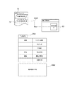
図21は、プリンターの印刷ドキュメントへの個別印刷設定データの格納動作例を説明するための図である。
プリンター3は、印刷設定UIの個別設定UI83の設定を、印刷ドキュメント70内に個別印刷設定73に格納する(2600)。この格納(2600)の際に、プリンター3は、個別印刷設定に情報を付加する。
付加情報は、表2601である。
機器の情報は、自機の[シリアル番号、モデル名、互換ID]である。
シリアル番号は、機体の固有番号である。モデル名は、機器名称かモデルのハードウェアID。互換IDは、モデル間で共用されるIDである。
日時の情報は、[設定日時]である。プリンター3は、印刷設定された日時の情報を付加する。なお、時間判別が難しいときは、プリンター3は、設定格納順のシリアル値で代用することができる。
期限の情報は[期限の有無、期限日時]である。
この期限は、主に印刷ドキュメントファイルが有効期限を持つときに、格納された印刷設定にも同等の有効期限を付与するため用いられる。プリンター3は、期限日時を過ぎた印刷設定を削除することができる。なお、プリンター3は、期限を、ファイルサイズの増加抑制等他の目的に用いることができる。
プリンター3は、印刷設定を行った機器、その日時情報を付加情報として記載し、個別印刷設定内容2602と合わせて印刷ドキュメント70に格納する。図20の説明の通り、プリンター3はこの付加情報を個別印刷設定の読み出し時に利用する。
以上、プリンター3の個別印刷設定への情報付加について説明した。プリンター3の印刷設定の格納及び情報付加処理のフローチャートは後述する。
次にプリンター3の印刷設定データの構築について説明する。
[Printer adds information for identification when storing individual print settings]
FIG. 21 is a diagram for explaining an example of the operation of storing the individual print setting data in the print document of the printer.
The
Additional information is shown in Table 2601.
The device information is [Serial number, model name, compatible ID] of the own device.
The serial number is a unique number of the aircraft. The model name is the device name or model hardware ID. The compatible ID is an ID shared between models.
The date / time information is [set date / time]. The
The deadline information is [existence of deadline, deadline date and time].
This time limit is mainly used to give an equivalent time limit to the stored print settings when the print document file has a time limit. The
The
The information addition to the individual print setting of the
Next, the construction of the print setting data of the
[プリンターの印刷時の設定データの構築について]
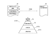
図22Aは、プリンターの印刷時における設定データの階層例を示した図である。
プリンター3は、印刷ドキュメント70、描画71と共通印刷設定72と個別印刷設定73とから印刷出力78を形成する(2700)。
2770では、印刷出力78の形成に関するプリンター3の設定データの階層構造の一例を示している。プリンター3の設定には、設定の工場出荷設定2771、現在の本体設定2772がある。工場出荷設定2771は、プリンター3の設定のデフォルト値にあたる。
本体設定2772は、プリンター3の動作に必要な印刷に限定されない設定や、印刷全体へ影響を与える設定である。例えば本体設定2772には、ネットワーク設定等が含まれる。
プリンター3の印刷時の設定は、これら工場出荷設定2771と本体設定2772とに、印刷ジョブに対する共通印刷設定72と個別印刷設定73とが適用される構造となる。共通印刷設定72は、個別印刷設定73に対して優先されてマージされ印刷ジョブに対する設定が形成される。
[About setting data for printer printing]
FIG. 22A is a diagram illustrating a hierarchy example of setting data at the time of printing by the printer.
The
The main body setting 2772 is a setting that is not limited to printing necessary for the operation of the
The setting at the time of printing of the
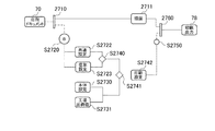
図22Bは、プリンター3の印刷時における設定データを構築するチャートである。
印刷ドキュメント70を入力とする。
制御部85は、描画と共通設定と個別設定とを印刷ドキュメント70から取り出す(2710)。
制御部85は、制御部85のデータ管理部87を印刷設定データ構築のためコールする。
ステップS2720から、データ管理部87は、フローB(Build)を開始する。
ステップS2722では、データ管理部87は、共通設定を選択する。
ステップS2723では、データ管理部87は、個別設定を選択する。
ステップS2730では、データ管理部87は、工場出荷値をロードする。
ステップS2731では、データ管理部87は、本体設定をロードする。
ステップS2740では、データ管理部87は、共通設定と個別設定とをマージする。
ステップS2741では、データ管理部87は、工場出荷値と本体設定と共通設定と個別設定とをマージする。
ステップS2742にて、データ管理部87は、構築した印刷設定を渡す。
ステップS2750にて、データ管理部87は、フローBを終了する。
制御部85は、データ管理部87から渡された印刷設定と描画を合わせて(2760)印刷を実行して、印刷出力78が出力される。
以上、プリンター3の印刷時の設定データの構築について説明した。
ここまでのプリンターの説明のまとめとして、次にプリンターの動作時の設定例を説明する。
FIG. 22B is a chart for constructing setting data during printing by the
The
The
The
From step S2720, the
In step S2722, the
In step S2723, the
In step S2730, the
In step S2731, the
In step S2740, the
In step S2741, the
In step S2742, the
In step S2750,
The
The construction of the setting data at the time of printing by the
As a summary of the description of the printer so far, an example of setting during operation of the printer will be described.
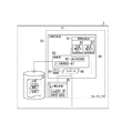
[プリンターのストレージ或いはプリント動作時の印刷設定例]
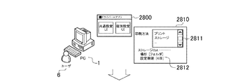
図23Aは、PCからプリンターへ、ストレージ或いはプリント動作を個別印刷設定する一例を示す図である。ユーザー6は、PC1上の印刷設定UI2800で印刷設定する。ダイアログ2810は、[印刷方法]の[プリント]と[ストレージ]との切り替え操作部(2811)を持つ。また、ユーザー6は、[ストレージオプション]で[フォルダ]や[設定期限](2812)の指定が行える。このダイアログ2810への設定も含む印刷ドキュメントがPC1からプリンター3へ送信される。
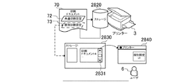
図23Bは、プリンターがストレージ動作時に個別印刷設定する一例を示す図である。
印刷ドキュメント70は、プリンター3のストレージ2820にある。プリンター3のストレージ画面2830には、ファイルリスト2831がある。ユーザー6は、印刷設定を参照・変更したいとき、印刷ドキュメントを選択して印刷設定UI2840を開く。印刷設定UI2840は、印刷ドキュメント70の個別印刷設定73を読み出して表示される。そして、ユーザー6が印刷設定UI2840に行った設定は、印刷ドキュメント70の個別印刷設定73に格納される。
図23Cは、プリンターがプリント動作時に個別印刷設定する一例を示す図である。
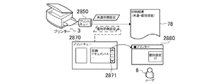
印刷ドキュメント70は、プリンター3のプリントキュー2850にある。プリンター3のプリントキュー画面2870には、ファイルリスト2871がある。ユーザー6は、印刷設定を参照・変更したいとき、印刷ドキュメントを選択して印刷設定UI2880を開く。印刷設定UI2880は、メモリに配置された個別印刷設定73を読み出して表示される。そして、ユーザー6が印刷設定UI2840に行った設定は、メモリの個別印刷設定73を更新し、印刷出力78へ印刷設定として反映される。
プリンター3のストレージ或いはプリント動作時の印刷設定処理のフローチャートは後述する。
図23Cでは、プリント動作時において、印刷ドキュメントから読み出され別記憶媒体上に置かれた個別印刷設定73を変更する方法を一例として説明した。つまり、プリンター3は、印刷ドキュメント70へ個別印刷設定73の再格納をしない方法でも印刷設定を変更することができる。印刷時に印刷キューへ印刷ドキュメント70を配置する方法であれば、前述のストレージ動作時と同処理となる。
[Print settings for printer storage or printing]
FIG. 23A is a diagram illustrating an example in which individual storage settings or print operations are set from a PC to a printer. The
FIG. 23B is a diagram illustrating an example in which the printer performs individual print settings during the storage operation.
The
FIG. 23C is a diagram illustrating an example in which the printer performs individual print settings during a print operation.
The
A flowchart of the print setting process during storage or printing operation of the
In FIG. 23C, the method of changing the individual print setting 73 read from the print document and placed on another storage medium during the print operation has been described as an example. That is, the
[プリンターの個別印刷設定データ読み出しのフローチャート]
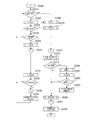
図24は、プリンター制御部の個別印刷設定読み出しのフローチャートである。
ステップS3000から、フローR1(Read1)が開始する。
ステップS3001から、制御部85は、印刷ドキュメント70からの設定読み出しを開始する。
ステップS3010から、制御部85は、共通設定の読み出しを開始する。
ステップS3011では、制御部85は、印刷ドキュメント70に共通設定が有ればステップS3012へ進み、共通設定が無ければステップS3013へ進む。
ステップS3012では、制御部85は、印刷ドキュメント70から共通設定をロードする。
ステップS3013では、制御部85は、プリンター3のデフォルト共通設定をロードする。
ステップS3014では、制御部85は、印刷ドキュメント70に個別印刷設定が有ればステップS3020へ進み、無ければステップS3045へ進む。
ステップS3020から、制御部85は、個別印刷設定の読み出しを開始する。
ステップS3021では、制御部85は、データ管理部87のフローR2をコールする。
ステップS3070では、制御部85は、データ管理部87が採用した個別設定が有るか確認し、採用の個別印刷設定が有ればステップS3080へ進み、無ければステップS3045へ進む。
ステップS3045では、制御部85は、現在のプリンター3の設定値をロードする。
ステップS3080では、制御部85は、印刷ドキュメント70の個別印刷設定をロードする。
ステップS3081では、制御部85は、個別印刷設定本体をBLOBデコードする。
ステップS3090にて、フローR1は終了する。
以上、プリンター3の個別印刷設定読み出しのフローチャートを説明した。
なお、図14と図24とは処理面で同等である。しかし、プリンター3の制御部85では、個別印刷設定データを参照するためのフローに特徴がある。続けて、その特徴であるプリンター3が適用個別印刷設定を判定するフローチャートを説明する。
[Flowchart for reading individual print setting data of printer]
FIG. 24 is a flowchart for reading the individual print settings of the printer control unit.
From step S3000, the flow R1 (Read1) starts.
From step S3001, the
From step S3010, the
In step S3011, the
In step S <b> 3012, the
In step S <b> 3013, the
In step S3014, the
From step S3020, the
In step S3021, the
In step S3070, the
In step S3045, the
In step S3080, the
In step S3081, the
In step S3090, flow R1 ends.
The flowchart for reading the individual print settings of the
14 and FIG. 24 are equivalent in terms of processing. However, the
[プリンターの個別印刷設定データ判別のフローチャート]
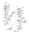
図25は、プリンターのデータ管理部87が個別印刷設定データを判別する時のフローチャートである。
プリンター3のデータ管理部87は、自機に適正な個別印刷設定を決定する。プリンター3のデータ管理部87は、機器条件や日時条件を判断し、自機が行った最新設定を最上位に選択する動作をする。
ステップS3100から、フローR2(Read2)が開始する。
ステップS3120から、データ管理部87は、個別印刷設定の確認を開始する。
ステップS3121から、データ管理部87は、付与情報の機器条件の確認を開始する。
ステップS3130から、データ管理部87は、機器条件で選別する。
ステップS3131では、データ管理部87は、自機のシリアルであるか確認し、自機のシリアルで有れば、ステップS3136へ進み、その個別設定を優先度1としてリストアップし、自機のシリアルで無ければステップS3132へ進む。
ステップS3132では、データ管理部87は、自機と同モデルであるか確認し、同モデルで有れば、ステップS3137へ進み、その個別設定を優先度2としてリストアップし、同モデルで無ければステップS3133へ進む。
ステップS3133では、データ管理部87は、自機と同シリーズであるが確認し、同シリーズで有れば、ステップS3138へ進み、その個別設定を優先度3としてリストアップし、同シリーズで無ければステップS3139へ進む。
ステップS3139では、データ管理部87は、印刷ドキュメント70内の個別印刷設定数のループを抜ける。
[Flowchart for individual printer setting data discrimination]
FIG. 25 is a flowchart when the
The
From step S3100, the flow R2 (Read2) starts.
From step S3120, the
From step S3121, the
From step S3130, the
In step S3131, the
In step S3132, the
In step S3133, the
In step S 3139, the
ステップS3140では、データ管理部87は、リストアップされた個別印刷設定が有るか確認し、リストアップされていればステップS3150へ進み、リストアップされていなければステップS3145へ進む。
ステップS3150から、データ管理部87は、優先度1〜3の順にリストアップした個別印刷設定の参照を開始する。
ステップS3151から、データ管理部87は、日時条件の確認を開始する。
ステップS3152では、データ管理部87は、設定日時が新しい順に個別印刷設定を参照する。
ステップS3160から、データ管理部87は、期限条件の確認を開始する。
ステップS3161では、データ管理部87は、期限が期限内であるか確認し、期限内で有ればステップS3162へ進み、期限内で無ければステップS3163へ進む。
ステップS3162では、データ管理部87は、採用する個別印刷設定を決定し、ステップS3165のループを抜ける。
ステップS3163では、データ管理部87は、期限が期限なしであるか確認し、期限なしで有ればステップS3162へ進み、期限なしで無ければステップS3164へ進む。
ステップS3164では、データ管理部87は、この個別印刷設定を削除する。
ステップS3165では、データ管理部87は、個別印刷設定のリストアップ数までのループを抜ける。
ステップS3170では、データ管理部87は、採用が決定した個別設定が有るか確認し、採用の個別印刷設定が有ればステップS3180へ進み、無ければステップS3145へ進む。
ステップS3145では、データ管理部87は、採用個別設定が無いとする。
ステップS3180では、データ管理部87は、採用した個別設定を示す。
ステップS3190にて、データ管理部87は、フローR2を終了する。
以上、プリンター3の個別印刷設定データ判別のフローチャートを説明した。続けてプリンター3の個別印刷設定格納のフローチャートを説明する。
In step S3140, the
From step S3150, the
From step S3151, the
In step S3152, the
From step S3160, the
In step S3161, the
In step S3162, the
In step S3163, the
In step S3164, the
In step S3165, the
In step S3170, the
In step S3145, it is assumed that the
In step S3180, the
In step S3190, the
The flowchart for determining the individual print setting data of the
[プリンターの個別印刷設定データ格納のフローチャート]
図26は、プリンター制御部の個別印刷設定格納のフローチャートである。
プリンター3の制御部85は、個別印刷設定の読み出し時に利用する条件を格納時に情報として付与する。プリンター3の制御部85は、印刷設定した機器、日時の情報を付与情報として記載し、個別印刷設定と合わせて格納する。
ステップS3200から、フローW(Write)が開始する。
ステップS3201から、制御部85は、印刷ドキュメント70への設定格納を開始
する。
ステップS3210では、制御部85は、個別印刷設定が実施されたか確認し、個別設定されたならステップS3220へ進み、個別設定されていないならステップS3250へ進む。
ステップS3220から、制御部85は、個別印刷設定の格納を開始する。
ステップS3230から、制御部85は、付加情報の形成を開始する。
ステップS3231では、制御部85は、本体シリアルとモデル名とHWIDと設定日時と有効期限とを付加する。
ステップS3240から、制御部85は、個別印刷設定本体の形成を開始する。
ステップS3241では、制御部85は、個別印刷設定UIから設定をエクスポートする。
ステップS3242では、制御部85は、個別印刷設定本体をBLOBエンコードする。
ステップS3243では、制御部85は、個別印刷設定を印刷ドキュメント70に格納する。
ステップS3250にて、フローWは終了する。
以上、プリンター3の個別印刷設定格納のフローチャートを説明した。次にプリンター3の印刷設定の動作の流れを説明する。
[Flow chart for storing individual print setting data of printer]
FIG. 26 is a flowchart for storing individual print settings in the printer control unit.
The
From step S3200, flow W (Write) starts.
From step S3201, the
In step S3210, the
From step S3220,
From step S3230,
In step S3231, the
From step S3240,
In step S3241, the
In step S3242, the
In step S3243, the
In step S3250, flow W ends.
The flowchart for storing the individual print settings of the
[プリンターのストレージ及びプリント動作時の印刷設定のフローチャート]
図27は、プリンター制御部のストレージ及びプリント動作時の印刷設定フローチャートである。
プリンター3の制御部85は、ここまで説明した個別印刷設定の読み出し、及び格納フローをコールする。プリンター3のストレージ時に印刷設定を更新すると、印刷設定が書き戻されて印刷ドキュメントは更新される。プリント動作時は、印刷設定を更新してもメモリ上の設定が更新され、印刷ドキュメントは更新されない。
ステップS3300から、フローP(Print)が開始する。
ステップS3310では、制御部85は、Storage(ストレージ)が指定されているか確認し、Storageが指定されていればステップS3320へ進み、Storageが指定されていなければS3360へ進む。
ステップS3320から、制御部85は、Storage処理を開始する。
ステップS3321では、制御部85は、Storageが無いか確認し、Storageが無いならステップS3360へ進み、StorageがあるならステップS3322へ進む。
ステップS3322では、制御部85は、Storage上での設定更新の指示を確認し、指示があればステップS3330へ進み、指示がなければステップS3310へ進む。
ステップS3330から、制御部85は、StorageにおけるUI設定を開始する。
ステップS3331では、制御部85は、フローR1をコールする。
ステップS3341では、制御部85は、印刷ドキュメント70から読みだした設定で設定UIを表示する。
ステップS3342では、制御部85は、設定UIのOKボタンが押されたか確認し、OKボタンが押されたならステップS3350へ進み、OKボタンが押されていないならステップS3310へ進む。
ステップS3350では、制御部85は、フローWをコールする。
ステップS3351では、制御部85は、印刷ドキュメント70を更新する。
[Flowchart of print settings during printer storage and printing]
FIG. 27 is a flowchart of print setting during storage and printing operation of the printer control unit.
The
From step S3300, the flow P (Print) starts.
In step S3310, the
From step S3320,
In step S3321, the
In step S3322, the
From step S3330, the
In step S3331, the
In step S3341, the
In step S3342, the
In step S3350,
In step S3351, the
ステップS3360から、制御部85は、Print処理を開始する。
ステップS3370から、制御部85は、印刷ドキュメント70を印刷キューへ送る。
ステップS3371では、制御部85は、フローR1をコールする。
ステップS3372では、制御部85は、共通印刷設定と個別印刷設定をメモリに配置する。
ステップS3373では、制御部85は、印刷キュー上での設定更新の指示を確認し、指示があればステップS3380へ進み、指示がなければ、ステップS3390へ進む。
ステップS3380から、制御部85は、PrintにおけるUI設定を開始する。
ステップS3381では、制御部85は、メモリ上の設定で印刷設定UIを表示する。
ステップS3382では、制御部85は、設定UIのOKボタンが押されたか確認し、OKボタンが押されたならステップS3383へ進み、OKボタンが押されていないならステップS3390へ進む。
ステップS3383では、制御部85は、メモリ上の設定を更新する。
ステップS3390から、制御部85は、印刷実行を開始する。
ステップS3391では、制御部85は、フローBをコールする。
ステップS3392では、制御部85は、印刷設定をジョブへ適用する。
以上、プリンター3の制御部85のストレージ及びプリント動作時の印刷設定フローチャートを説明した。
From step S3360,
From step S3370,
In step S3371, the
In step S3372, the
In step S3373, the
From step S3380,
In step S3381, the
In step S3382, the
In step S3383, the
From step S3390,
In step S3391, the
In step S3392, the
In the foregoing, the storage of the
[プリンターの実施形態の効果の説明]
本実施形態によれば、プリンター3は、印刷ドキュメント内から印刷設定を抽出し、2つのUI(RUI、LUI)に表示及び編集可能である。
また、本実施形態によれば、プリンター3は、各種装置上のUIで編集された印刷設定から、適用すべき印刷設定を判別する。
次のような印刷設定に関する操作性が向上する効果がある。
ユーザーは、PC1、プリンター3等各種装置上で印刷設定ができる。プリンター3は、適用する印刷設定を判別して、プリンター3のUIに表示する。ユーザーはプリンター3のUI表示を参照し必要箇所のみ設定変更して印刷実行できる。
[Description of effects of printer embodiment]
According to the present embodiment, the
Further, according to the present embodiment, the
There is an effect that the operability related to the following print setting is improved.
The user can make print settings on various devices such as the
〔本システムの特徴〕
図28Aは、本実施形態を適用しやすい製品構成を説明するための図である。
本実施形態の構成は、WAN環境における印刷であるためダイレクトプリントシステムへの適合性が高い。ダイレクトプリントとは、図28Aのように印刷ドキュメント70をプリンター3が受信して印刷出力78を行うシステムである。印刷ドキュメント70としては、XPSドキュメント、或いは同等仕様を有するドキュメントの適合性が高い。その理由は、XPSドキュメントが描画リソースと印刷設定とを内包していて、印刷外観が決まった(Fixedな)ドキュメントコンテンツであるからである。印刷設定によって描画本体を大きく変更する必要があるドキュメントコンテンツ及びプリンターシステムは、プリンターが特定できない環境下での動作が難しくなる。リモートのプリンターUIは、動作環境としてWebブラウザを利用するUI機構が適している。プリンター3の外部UIは、Webブラウザ上で実行されるスクリプトやプログラムであると特に適合性がよい。PC1上へ表示時にダウンロードされたUIが処理を行うことで、プリンター3の負荷を減らすことができる。
ソフトウェア(SW)としては、汎用型のプリンタードライバー、Webベースのアプリケーションの適合性が高い。これらのソフトウェアは、WAN環境で標準的な印刷設定を対象とした印刷処理する機会が多いからである。汎用型プリンタードライバーは、その汎用型のドライバーUIとプリンターUI(リモート)とを組み合わせることにより本実施と同等の構成となる。本システムにおいて、プリンター毎の差異(1701)は、個別設定UI83(プリンター)とプリンター3自身とが対応することになる。よってWebベースのアプリケーションは、共通印刷設定に対応すれば、多数デバイスをサポートできるようになる。
[Features of this system]
FIG. 28A is a diagram for explaining a product configuration to which the present embodiment can be easily applied.
Since the configuration of this embodiment is printing in a WAN environment, it is highly compatible with a direct print system. Direct printing is a system in which the
As software (SW), the compatibility of general-purpose printer drivers and Web-based applications is high. This is because these software have many opportunities to perform print processing for standard print settings in a WAN environment. The general-purpose printer driver has the same configuration as the present embodiment by combining the general-purpose driver UI and the printer UI (remote). In this system, the difference (1701) for each printer corresponds to the individual setting UI 83 (printer) and the
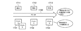
図28Bは、本システムのデバイス・サポート・ライフサイクルを説明するための図である。
前述のとおり、本システムのPC ソフトウェア(PC SW)は、共通設定を担当し、かつ、プリンター依存する個別設定の内容にアクセスしない。この分担によりソフトウェアは、プリンターのリリース毎の開発と頒布が必須ではなくなっている(1720)。
従来のシステムでは、現在1712に頒布するソフトウェアは過去1711のプリンターA、B(1731)と現在1712のプリンターC(1732)とに対応するが、未知の仕様である将来1713のプリンターD1733には対応できなかった。従来のシステムは、過去1711、現在1712、将来1713の3回で、別々ソフトウェアをリリースする或いはソフトウェアを更新していた。本システムなら、将来1713のプリンターD1733も、後に設置すれば利用可能となる。
デバイスを接続すると共通印刷設定の範囲では印刷ができる。また、ソフトウェアの再インストールは必須でなく、将来デバイスのフル機能が利用できる。WANのように広範囲にソフトウェアを設置して印刷サービスを構築するとき、この設置性や即時性は重要である。以上、効果を補足するため、本システムの特徴を説明した。
ここまで説明を行なってきた印刷設定部80は、ソフト構成やデータの一部をサーバーへ置く、他所へ配信する等、構成の配置や形式を変更してもよい。
FIG. 28B is a diagram for explaining the device support life cycle of this system.
As described above, the PC software (PC SW) of this system is responsible for common settings and does not access the contents of the individual settings depending on the printer. This sharing makes it unnecessary for software to be developed and distributed every time the printer is released (1720).
In the conventional system, the software currently distributed to 1712 corresponds to the printers A and B (1731) of the past 1711 and the printer C (1732) of the current 1712, but corresponds to the future printer D1733 of the unknown 1713. could not. The conventional system releases separate software or updates software in the past 1711, present 1712, and future 1713 three times. In the case of this system, the
When a device is connected, printing is possible within the range of common print settings. Moreover, it is not necessary to reinstall the software, and the full function of the device can be used in the future. This installability and immediacy are important when installing a software with a wide range of software installation like WAN. In the above, in order to supplement an effect, the feature of this system was explained.
The
<その他の実施形態>
また、本発明は、以下の処理を実行することによっても実現される。即ち、上述した実施形態の機能を実現するソフトウェア(プログラム)を、ネットワーク又は各種記憶媒体を介してシステム或いは装置に供給し、そのシステム或いは装置のコンピュータ(又はCPUやMPU等)がプログラムを読み出して実行する処理である。
<Other embodiments>
The present invention can also be realized by executing the following processing. That is, software (program) that realizes the functions of the above-described embodiments is supplied to a system or apparatus via a network or various storage media, and a computer (or CPU, MPU, etc.) of the system or apparatus reads the program. It is a process to be executed.
以上、上述した各実施形態によれば、プリンターが不定となる環境下においてもユーザーに一定の印刷設定操作を提供すると共に、出力するプリンターが確定すると、プリンターのフル機能を利用可能にすることができる。
また、上述した各実施形態によれば、非PC環境、ダイレクトプリント経路でも印刷設定ができる。
また、上述した各実施形態によれば、ドキュメントデータ内の印刷設定をデバイスのリモートUIで編集できる。
As described above, according to each of the above-described embodiments, it is possible to provide a user with a certain print setting operation even in an environment where the printer is indefinite, and to make the full function of the printer available when the output printer is determined. it can.
Further, according to each of the above-described embodiments, print settings can be made even in a non-PC environment and a direct print path.
Further, according to each of the above-described embodiments, the print setting in the document data can be edited with the remote UI of the device.
以上、本発明の好ましい実施形態について詳述したが、本発明は係る特定の実施形態に限定されるものではなく、特許請求の範囲に記載された本発明の要旨の範囲内において、種々の変形・変更が可能である。 The preferred embodiments of the present invention have been described in detail above, but the present invention is not limited to such specific embodiments, and various modifications can be made within the scope of the gist of the present invention described in the claims.・ Change is possible.
Claims (14)
環境変数にリモートの個別設定画面を指し示すデータが存在し、かつ、画像処理装置と通信可能である場合、印刷設定画面に前記画像処理装置の個別設定画面を表示するよう制御し、
環境変数にリモートの個別設定画面を指し示すデータが存在し、かつ、画像処理装置と通信不可能である場合、印刷設定画面に個別設定画面を表示しないよう制御し、
環境変数にローカルの個別設定画面を指し示すデータが存在する場合、印刷設定画面にローカルの個別設定画面を表示するよう制御する請求項3記載の情報処理装置。 The display control means includes
If there is data pointing to the remote individual setting screen in the environment variable and communication with the image processing apparatus is possible, control is performed to display the individual setting screen of the image processing apparatus on the print setting screen,
If there is data pointing to the remote individual setting screen in the environment variable and communication with the image processing device is not possible, control to not display the individual setting screen on the print setting screen,
4. The information processing apparatus according to claim 3, wherein when there is data indicating the local individual setting screen in the environment variable, the local individual setting screen is controlled to be displayed on the print setting screen.
印刷設定画面を表示するステップと、
前記印刷設定画面に画像処理装置の機種に依存しない共通設定を設定可能な共通設定画面を表示するステップと、
前記印刷設定画面に画像処理装置の機種に依存する個別設定を設定可能な個別設定画面を表示するステップと、
を含む情報処理方法。 An information processing method executed by an information processing apparatus,
Displaying the print settings screen;
Displaying a common setting screen in which common settings independent of the model of the image processing apparatus can be set on the print setting screen;
Displaying an individual setting screen on which the individual setting depending on the model of the image processing apparatus can be set on the print setting screen;
An information processing method including:
印刷設定画面を表示するステップと、
前記印刷設定画面に画像処理装置の機種に依存しない共通設定を設定可能な共通設定画面を表示するステップと、
前記印刷設定画面に画像処理装置の機種に依存する個別設定を設定可能な個別設定画面を表示するステップと、
を実行させるプログラム。 On the computer,
Displaying the print settings screen;
Displaying a common setting screen in which common settings independent of the model of the image processing apparatus can be set on the print setting screen;
Displaying an individual setting screen on which the individual setting depending on the model of the image processing apparatus can be set on the print setting screen;
A program that executes
前記情報処理装置の共通印刷設定画面と前記画像処理装置の個別印刷設定画面とを含む設定画面を表示する表示手段と、
前記表示手段に表示された共通印刷設定画面と個別印刷設定画面とを含む設定画面で設定された共通印刷設定と個別印刷設定とを印刷ドキュメントに設定する設定手段と、
前記設定手段で前記共通印刷設定と前記個別印刷設定とを設定された印刷ドキュメントを前記画像処理装置に送信する送信手段と、
を有する情報処理装置。 An information processing apparatus that transmits a print document to an image processing apparatus,
Display means for displaying a setting screen including a common print setting screen of the information processing apparatus and an individual print setting screen of the image processing apparatus;
Setting means for setting a common print setting and an individual print setting set in a setting screen including a common print setting screen and an individual print setting screen displayed on the display means in a print document;
A transmission unit configured to transmit the print document in which the common print setting and the individual print setting are set by the setting unit to the image processing apparatus;
An information processing apparatus.
前記情報処理装置の共通印刷設定画面と前記画像処理装置の個別印刷設定画面とを含む設定画面を表示する表示ステップと、
前記表示ステップに表示された共通印刷設定画面と個別印刷設定画面とを含む設定画面で設定された共通印刷設定と個別印刷設定とを印刷ドキュメントに設定する設定ステップと、
前記設定ステップで前記共通印刷設定と前記個別印刷設定とを設定された印刷ドキュメントを前記画像処理装置に送信する送信ステップと、
を含む情報処理方法。 An information processing method executed by an information processing apparatus that transmits a print document to an image processing apparatus,
A display step for displaying a setting screen including a common print setting screen of the information processing apparatus and an individual print setting screen of the image processing apparatus;
A setting step for setting a common print setting and an individual print setting set in a setting screen including a common print setting screen and an individual print setting screen displayed in the display step in a print document;
A transmission step of transmitting the print document in which the common print setting and the individual print setting are set in the setting step to the image processing apparatus;
An information processing method including:
前記コンピュータの共通印刷設定画面と前記画像処理装置の個別印刷設定画面とを含む設定画面を表示する表示手段と、
前記表示手段に表示された共通印刷設定画面と個別印刷設定画面とを含む設定画面で設定された共通印刷設定と個別印刷設定とを印刷ドキュメントに設定する設定手段と、
前記設定手段で前記共通印刷設定と前記個別印刷設定とを設定された印刷ドキュメントを前記画像処理装置に送信する送信手段と、
して機能させるためのプログラム。 A computer that sends a print document to an image processing device;
Display means for displaying a setting screen including a common print setting screen of the computer and an individual print setting screen of the image processing apparatus;
Setting means for setting a common print setting and an individual print setting set in a setting screen including a common print setting screen and an individual print setting screen displayed on the display means in a print document;
A transmission unit configured to transmit the print document in which the common print setting and the individual print setting are set by the setting unit to the image processing apparatus;
Program to make it function.
前記画像処理装置の個別印刷設定画面を含む設定画面で設定された個別印刷設定が設定された印刷ドキュメントを前記情報処理装置から受信する受信手段と、
前記受信手段で受信された前記印刷ドキュメントに設定された前記個別印刷設定を読み取り、前記個別印刷設定を反映させた設定画面を表示する表示手段と、
前記表示手段で表示された設定画面で設定された個別印刷設定を前記印刷ドキュメントに設定する設定手段と、
前記印刷ドキュメントに設定された前記個別印刷設定に基づいて前記印刷ドキュメントを印刷するよう制御する印刷制御手段と、
を有する画像処理装置。 An image processing apparatus for printing a print document transmitted from an information processing apparatus,
Receiving means for receiving, from the information processing apparatus, a print document in which individual print settings set on a setting screen including an individual print setting screen of the image processing apparatus are set;
Display means for reading the individual print settings set in the print document received by the receiving means and displaying a setting screen reflecting the individual print settings;
Setting means for setting individual print settings set in the setting screen displayed by the display means in the print document;
Print control means for controlling to print the print document based on the individual print settings set for the print document;
An image processing apparatus.
前記画像処理装置の個別印刷設定画面を含む設定画面で設定された個別印刷設定が設定された印刷ドキュメントを前記情報処理装置から受信する受信ステップと、
前記受信ステップで受信された前記印刷ドキュメントに設定された前記個別印刷設定を読み取り、前記個別印刷設定を反映させた設定画面を表示する表示ステップと、
前記表示ステップで表示された設定画面で設定された個別印刷設定を前記印刷ドキュメントに設定する設定ステップと、
前記印刷ドキュメントに設定された前記個別印刷設定に基づいて前記印刷ドキュメントを印刷するよう制御する印刷制御ステップと、
を含む画像処理方法。 An image processing method executed by an image processing apparatus that prints a print document transmitted from an information processing apparatus,
A receiving step of receiving, from the information processing apparatus, a print document in which individual print settings set on a setting screen including an individual print setting screen of the image processing apparatus are set;
A display step of reading the individual print settings set in the print document received in the reception step and displaying a setting screen reflecting the individual print settings;
A setting step of setting individual print settings set on the setting screen displayed in the display step in the print document;
A print control step for controlling to print the print document based on the individual print settings set for the print document;
An image processing method including:
前記コンピュータの個別印刷設定画面を含む設定画面で設定された個別印刷設定が設定された印刷ドキュメントを前記情報処理装置から受信する受信手段と、
前記受信手段で受信された前記印刷ドキュメントに設定された前記個別印刷設定を読み取り、前記個別印刷設定を反映させた設定画面を表示する表示手段と、
前記表示手段で表示された設定画面で設定された個別印刷設定を前記印刷ドキュメントに設定する設定手段と、
前記印刷ドキュメントに設定された前記個別印刷設定に基づいて前記印刷ドキュメントを印刷するよう制御する印刷制御手段と、
して機能させるためのプログラム。 A computer that prints a print document sent from an information processing device.
Receiving means for receiving, from the information processing apparatus, a print document in which individual print settings set on a setting screen including an individual print setting screen of the computer are set;
Display means for reading the individual print settings set in the print document received by the receiving means and displaying a setting screen reflecting the individual print settings;
Setting means for setting individual print settings set in the setting screen displayed by the display means in the print document;
Print control means for controlling to print the print document based on the individual print settings set for the print document;
Program to make it function.
前記情報処理装置は、
前記画像処理装置の個別印刷設定画面を含む設定画面を表示する表示手段と、
前記表示手段に表示された個別印刷設定画面を含む設定画面で設定された個別印刷設定を印刷ドキュメントに設定する設定手段と、
前記設定手段で前記個別印刷設定を設定された印刷ドキュメントを前記画像処理装置に送信する送信手段と、
を有し、
前記画像処理装置は、
前記情報処理装置の前記画像処理装置の個別印刷設定画面を含む設定画面で設定された個別印刷設定が設定された印刷ドキュメントを前記情報処理装置から受信する受信手段と、
前記受信手段で受信された前記印刷ドキュメントに設定された前記個別印刷設定を読み取り、前記個別印刷設定を反映させた設定画面を表示する表示手段と、
前記表示手段で表示された設定画面で設定された個別印刷設定を前記印刷ドキュメントに設定する設定手段と、
前記印刷ドキュメントに設定された前記個別印刷設定に基づいて前記印刷ドキュメントを印刷するよう制御する印刷制御手段と、
を有するシステム。 A system including an information processing device and an image processing device,
The information processing apparatus includes:
Display means for displaying a setting screen including an individual print setting screen of the image processing apparatus;
Setting means for setting an individual print setting set on a setting screen including an individual print setting screen displayed on the display means in a print document;
A transmission unit configured to transmit the print document in which the individual print setting is set by the setting unit to the image processing apparatus;
Have
The image processing apparatus includes:
Receiving means for receiving, from the information processing apparatus, a print document in which individual print settings set on a setting screen including an individual print setting screen of the image processing apparatus of the information processing apparatus are set;
Display means for reading the individual print settings set in the print document received by the receiving means and displaying a setting screen reflecting the individual print settings;
Setting means for setting individual print settings set in the setting screen displayed by the display means in the print document;
Print control means for controlling to print the print document based on the individual print settings set for the print document;
Having a system.
前記情報処理装置が、前記画像処理装置の個別印刷設定画面を含む設定画面を表示するステップと、
前記情報処理装置が、前記ステップに表示された個別印刷設定画面を含む設定画面で設定された個別印刷設定を印刷ドキュメントに設定するステップと、
前記情報処理装置が、前記ステップで前記個別印刷設定を設定された印刷ドキュメントを前記画像処理装置に送信するステップと、
前記画像処理装置が、前記情報処理装置の前記画像処理装置の個別印刷設定画面を含む設定画面で設定された個別印刷設定が設定された印刷ドキュメントを前記情報処理装置から受信するステップと、
前記画像処理装置が、前記ステップで受信された前記印刷ドキュメントに設定された前記個別印刷設定を読み取り、前記個別印刷設定を反映させた設定画面を表示するステップと、
前記画像処理装置が、前記ステップで表示された設定画面で設定された個別印刷設定を前記印刷ドキュメントに設定するステップと、
前記画像処理装置が、前記印刷ドキュメントに設定された前記個別印刷設定に基づいて前記印刷ドキュメントを印刷するよう制御するステップと、
を含む画像処理方法。 An image processing method in a system including an information processing device and an image processing device,
The information processing apparatus displaying a setting screen including an individual print setting screen of the image processing apparatus;
The information processing apparatus setting an individual print setting set in a setting screen including the individual print setting screen displayed in the step in a print document;
The information processing apparatus transmitting the print document in which the individual print setting is set in the step to the image processing apparatus;
The image processing apparatus receiving from the information processing apparatus a print document in which individual print settings set on a setting screen including an individual print setting screen of the image processing apparatus of the information processing apparatus are set;
The image processing apparatus reading the individual print settings set in the print document received in the step, and displaying a setting screen reflecting the individual print settings;
The image processing apparatus setting an individual print setting set in the setting screen displayed in the step in the print document;
Controlling the image processing apparatus to print the print document based on the individual print settings set for the print document;
An image processing method including:
Priority Applications (2)
| Application Number | Priority Date | Filing Date | Title |
|---|---|---|---|
| JP2011147414A JP5836667B2 (en) | 2010-11-17 | 2011-07-01 | Information processing apparatus, information processing method, program, system, and image processing method |
| US13/290,465 US9122428B2 (en) | 2010-11-17 | 2011-11-07 | Information processing apparatus allowing a user certain print setting operations in an environment where an image processing apparatus is undetermined |
Applications Claiming Priority (3)
| Application Number | Priority Date | Filing Date | Title |
|---|---|---|---|
| JP2010257213 | 2010-11-17 | ||
| JP2010257213 | 2010-11-17 | ||
| JP2011147414A JP5836667B2 (en) | 2010-11-17 | 2011-07-01 | Information processing apparatus, information processing method, program, system, and image processing method |
Publications (2)
| Publication Number | Publication Date |
|---|---|
| JP2012123778A true JP2012123778A (en) | 2012-06-28 |
| JP5836667B2 JP5836667B2 (en) | 2015-12-24 |
Family
ID=46047507
Family Applications (1)
| Application Number | Title | Priority Date | Filing Date |
|---|---|---|---|
| JP2011147414A Active JP5836667B2 (en) | 2010-11-17 | 2011-07-01 | Information processing apparatus, information processing method, program, system, and image processing method |
Country Status (2)
| Country | Link |
|---|---|
| US (1) | US9122428B2 (en) |
| JP (1) | JP5836667B2 (en) |
Cited By (5)
| Publication number | Priority date | Publication date | Assignee | Title |
|---|---|---|---|---|
| JP2015215825A (en) * | 2014-05-13 | 2015-12-03 | 株式会社リコー | Output system, terminal device, program, and output method |
| US9612787B2 (en) | 2014-04-18 | 2017-04-04 | Canon Kabushiki Kaisha | Information processing apparatus and control method thereof |
| JP2018014135A (en) * | 2017-10-12 | 2018-01-25 | 株式会社リコー | Output system, terminal device, program, and output method |
| JP2020154729A (en) * | 2019-03-20 | 2020-09-24 | 株式会社リコー | Information processing equipment, image forming equipment, information processing system, and programs |
| JP2021033526A (en) * | 2019-08-21 | 2021-03-01 | キヤノン株式会社 | Server system and application |
Families Citing this family (5)
| Publication number | Priority date | Publication date | Assignee | Title |
|---|---|---|---|---|
| JP6074179B2 (en) * | 2012-07-05 | 2017-02-01 | キヤノン株式会社 | Printing control apparatus, printing system, and printing method |
| US9665314B2 (en) | 2014-04-03 | 2017-05-30 | Canon Kabushiki Kaisha | Methods and systems for managing a print-setting user interface |
| JP6784163B2 (en) * | 2016-12-14 | 2020-11-11 | コニカミノルタ株式会社 | Electronic device setting device and program |
| JP2023089802A (en) * | 2021-12-16 | 2023-06-28 | キヤノン株式会社 | Information processing device, control method for information processing device, and program |
| JP7790236B2 (en) * | 2022-03-28 | 2025-12-23 | ブラザー工業株式会社 | Support Program |
Citations (3)
| Publication number | Priority date | Publication date | Assignee | Title |
|---|---|---|---|---|
| JP2007280269A (en) * | 2006-04-11 | 2007-10-25 | Konica Minolta Business Technologies Inc | Information processor, image formation condition setting method and image formation condition setting program |
| JP2010072679A (en) * | 2008-09-16 | 2010-04-02 | Fuji Xerox Co Ltd | Image forming system, image forming apparatus, terminal device, printing control method and program |
| JP2010250532A (en) * | 2009-04-15 | 2010-11-04 | Konica Minolta Business Technologies Inc | Apparatus and program for instructing output |
Family Cites Families (12)
| Publication number | Priority date | Publication date | Assignee | Title |
|---|---|---|---|---|
| JP3634784B2 (en) * | 2001-09-14 | 2005-03-30 | キヤノン株式会社 | Information processing method and print control apparatus |
| JP4458479B2 (en) * | 2005-01-26 | 2010-04-28 | 株式会社リコー | Information processing device |
| JP4863456B2 (en) | 2005-06-07 | 2012-01-25 | キヤノン株式会社 | Printer and printing method |
| US20060291005A1 (en) * | 2005-06-28 | 2006-12-28 | Konica Minolta Business Technologies, Inc. | Method of setting image reading conditions for an image reading apparatus and an image reading apparatus |
| JP4630751B2 (en) | 2005-07-28 | 2011-02-09 | キヤノン株式会社 | Printing system, printing apparatus, control method therefor, and program |
| JP2008083741A (en) * | 2006-09-25 | 2008-04-10 | Oki Data Corp | Image processing device |
| JP4914251B2 (en) * | 2007-03-07 | 2012-04-11 | 株式会社リコー | Information processing apparatus, information processing program, and recording medium |
| JP5283969B2 (en) * | 2007-05-31 | 2013-09-04 | キヤノン株式会社 | Information processing apparatus and information processing apparatus control method |
| JP4942198B2 (en) * | 2007-11-15 | 2012-05-30 | キヤノン株式会社 | Printing system, client terminal device and printing control method |
| JP4974909B2 (en) * | 2008-01-10 | 2012-07-11 | キヤノン株式会社 | Information processing apparatus, print setting method, storage medium, program |
| JP5078686B2 (en) * | 2008-03-18 | 2012-11-21 | キヤノン株式会社 | Print setting processing apparatus and print setting processing method |
| JP4831147B2 (en) * | 2008-09-04 | 2011-12-07 | ブラザー工業株式会社 | Device driver and recording medium |
-
2011
- 2011-07-01 JP JP2011147414A patent/JP5836667B2/en active Active
- 2011-11-07 US US13/290,465 patent/US9122428B2/en active Active
Patent Citations (3)
| Publication number | Priority date | Publication date | Assignee | Title |
|---|---|---|---|---|
| JP2007280269A (en) * | 2006-04-11 | 2007-10-25 | Konica Minolta Business Technologies Inc | Information processor, image formation condition setting method and image formation condition setting program |
| JP2010072679A (en) * | 2008-09-16 | 2010-04-02 | Fuji Xerox Co Ltd | Image forming system, image forming apparatus, terminal device, printing control method and program |
| JP2010250532A (en) * | 2009-04-15 | 2010-11-04 | Konica Minolta Business Technologies Inc | Apparatus and program for instructing output |
Cited By (7)
| Publication number | Priority date | Publication date | Assignee | Title |
|---|---|---|---|---|
| US9612787B2 (en) | 2014-04-18 | 2017-04-04 | Canon Kabushiki Kaisha | Information processing apparatus and control method thereof |
| JP2015215825A (en) * | 2014-05-13 | 2015-12-03 | 株式会社リコー | Output system, terminal device, program, and output method |
| JP2018014135A (en) * | 2017-10-12 | 2018-01-25 | 株式会社リコー | Output system, terminal device, program, and output method |
| JP2020154729A (en) * | 2019-03-20 | 2020-09-24 | 株式会社リコー | Information processing equipment, image forming equipment, information processing system, and programs |
| JP7287035B2 (en) | 2019-03-20 | 2023-06-06 | 株式会社リコー | Information processing device, information processing system, and program |
| JP2021033526A (en) * | 2019-08-21 | 2021-03-01 | キヤノン株式会社 | Server system and application |
| JP7321827B2 (en) | 2019-08-21 | 2023-08-07 | キヤノン株式会社 | Information processing device control method, print setting application, and information processing device |
Also Published As
| Publication number | Publication date |
|---|---|
| JP5836667B2 (en) | 2015-12-24 |
| US9122428B2 (en) | 2015-09-01 |
| US20120120443A1 (en) | 2012-05-17 |
Similar Documents
| Publication | Publication Date | Title |
|---|---|---|
| JP5836667B2 (en) | Information processing apparatus, information processing method, program, system, and image processing method | |
| US12229458B2 (en) | Print processing system and control method | |
| JP7691456B2 (en) | PROGRAM, METHOD FOR CONTROLLING INFORMATION PROCESSING APPARATUS AND INFORMATION PROCESSING APPARATUS | |
| US9442678B2 (en) | Information processing apparatus, information processing system and non-transitory computer-readable information recording medium | |
| JP5478937B2 (en) | Information processing apparatus, control method, and program | |
| US9830544B2 (en) | Image processing apparatus, control method, and storage medium for executing print processing using a password including selecting a personal identification code type that indicates a purpose for using the password | |
| EP2388685B1 (en) | Information processing apparatus and control method thereof, and storage medium | |
| US20230333794A1 (en) | Information processing apparatus, control method of information processing apparatus, and non-transitory computer-readable storage medium | |
| JP5527992B2 (en) | Print control method, print control apparatus, and computer program | |
| JP2024052771A (en) | Information processing device, control method, and program | |
| US11842089B2 (en) | Information processing apparatus, control method of information processing apparatus, and storage medium for setting a setting value of a print setting | |
| KR20210098343A (en) | Information processing apparatus, control method and program therefor, and server system capable of communicating with the information processing apparatus | |
| US8159701B2 (en) | Printer driver, apparatus and methods for conrolling a printer from a devmode data structure | |
| JP2017033052A (en) | Control device and program in image forming apparatus | |
| US8159702B2 (en) | Printer driver, apparatus and methods for controlling a printer from a devmode data structure | |
| JP2005301890A (en) | Extended control apparatus, image forming system, application activation switching method, image forming system control method, program, and recording medium | |
| US9081530B2 (en) | Control system for forming and outputting image, control apparatus for forming and outputting image, and recording medium storing a control program for forming and outputting image | |
| JP2006107301A (en) | Extended control unit | |
| JP5697393B2 (en) | Information processing apparatus, peripheral device control method, and program | |
| JP5726344B2 (en) | Information processing apparatus, control method, and program | |
| JP7171227B2 (en) | Information processing device, its control method and application | |
| CN110764720A (en) | Printing apparatus, control method of printing apparatus, and storage medium | |
| JP7562327B2 (en) | Information processing device, control method for information processing device, and program | |
| JP2006228128A (en) | Information processing apparatus, communication device control apparatus, and program | |
| JP7066518B2 (en) | Program and control method |
Legal Events
| Date | Code | Title | Description |
|---|---|---|---|
| A621 | Written request for application examination |
Free format text: JAPANESE INTERMEDIATE CODE: A621 Effective date: 20140627 |
|
| A977 | Report on retrieval |
Free format text: JAPANESE INTERMEDIATE CODE: A971007 Effective date: 20150424 |
|
| A131 | Notification of reasons for refusal |
Free format text: JAPANESE INTERMEDIATE CODE: A131 Effective date: 20150526 |
|
| A521 | Request for written amendment filed |
Free format text: JAPANESE INTERMEDIATE CODE: A523 Effective date: 20150616 |
|
| A131 | Notification of reasons for refusal |
Free format text: JAPANESE INTERMEDIATE CODE: A131 Effective date: 20150714 |
|
| A521 | Request for written amendment filed |
Free format text: JAPANESE INTERMEDIATE CODE: A523 Effective date: 20150803 |
|
| TRDD | Decision of grant or rejection written | ||
| A01 | Written decision to grant a patent or to grant a registration (utility model) |
Free format text: JAPANESE INTERMEDIATE CODE: A01 Effective date: 20151006 |
|
| A61 | First payment of annual fees (during grant procedure) |
Free format text: JAPANESE INTERMEDIATE CODE: A61 Effective date: 20151104 |
|
| R151 | Written notification of patent or utility model registration |
Ref document number: 5836667 Country of ref document: JP Free format text: JAPANESE INTERMEDIATE CODE: R151 |