JP2012123768A - Foot switch system - Google Patents
Foot switch system Download PDFInfo
- Publication number
- JP2012123768A JP2012123768A JP2010288690A JP2010288690A JP2012123768A JP 2012123768 A JP2012123768 A JP 2012123768A JP 2010288690 A JP2010288690 A JP 2010288690A JP 2010288690 A JP2010288690 A JP 2010288690A JP 2012123768 A JP2012123768 A JP 2012123768A
- Authority
- JP
- Japan
- Prior art keywords
- rfid
- footwear
- rfid tag
- rfid reader
- switch system
- Prior art date
- Legal status (The legal status is an assumption and is not a legal conclusion. Google has not performed a legal analysis and makes no representation as to the accuracy of the status listed.)
- Pending
Links
- 238000012544 monitoring process Methods 0.000 claims abstract description 22
- 230000033001 locomotion Effects 0.000 claims abstract description 12
- 238000013459 approach Methods 0.000 claims description 6
- 238000004891 communication Methods 0.000 claims description 5
- 230000008713 feedback mechanism Effects 0.000 claims description 2
- 230000001960 triggered effect Effects 0.000 claims description 2
- 230000037396 body weight Effects 0.000 abstract description 2
- 238000012806 monitoring device Methods 0.000 abstract 1
- 238000000034 method Methods 0.000 description 9
- 230000000694 effects Effects 0.000 description 7
- 238000012550 audit Methods 0.000 description 4
- 230000002411 adverse Effects 0.000 description 3
- 238000010586 diagram Methods 0.000 description 3
- 230000005540 biological transmission Effects 0.000 description 2
- 238000010411 cooking Methods 0.000 description 2
- 239000003814 drug Substances 0.000 description 2
- 229940079593 drug Drugs 0.000 description 2
- 238000002347 injection Methods 0.000 description 2
- 239000007924 injection Substances 0.000 description 2
- 238000011109 contamination Methods 0.000 description 1
- 238000005516 engineering process Methods 0.000 description 1
- 239000004744 fabric Substances 0.000 description 1
- 239000004973 liquid crystal related substance Substances 0.000 description 1
- 238000002360 preparation method Methods 0.000 description 1
- 238000005086 pumping Methods 0.000 description 1
- 230000002285 radioactive effect Effects 0.000 description 1
- 238000011160 research Methods 0.000 description 1
- 238000009958 sewing Methods 0.000 description 1
- 230000001429 stepping effect Effects 0.000 description 1
- 239000002344 surface layer Substances 0.000 description 1
Images


Classifications
-
- C—CHEMISTRY; METALLURGY
- C12—BIOCHEMISTRY; BEER; SPIRITS; WINE; VINEGAR; MICROBIOLOGY; ENZYMOLOGY; MUTATION OR GENETIC ENGINEERING
- C12M—APPARATUS FOR ENZYMOLOGY OR MICROBIOLOGY; APPARATUS FOR CULTURING MICROORGANISMS FOR PRODUCING BIOMASS, FOR GROWING CELLS OR FOR OBTAINING FERMENTATION OR METABOLIC PRODUCTS, i.e. BIOREACTORS OR FERMENTERS
- C12M37/00—Means for sterilizing, maintaining sterile conditions or avoiding chemical or biological contamination
-
- C—CHEMISTRY; METALLURGY
- C12—BIOCHEMISTRY; BEER; SPIRITS; WINE; VINEGAR; MICROBIOLOGY; ENZYMOLOGY; MUTATION OR GENETIC ENGINEERING
- C12M—APPARATUS FOR ENZYMOLOGY OR MICROBIOLOGY; APPARATUS FOR CULTURING MICROORGANISMS FOR PRODUCING BIOMASS, FOR GROWING CELLS OR FOR OBTAINING FERMENTATION OR METABOLIC PRODUCTS, i.e. BIOREACTORS OR FERMENTERS
- C12M41/00—Means for regulation, monitoring, measurement or control, e.g. flow regulation
- C12M41/48—Automatic or computerized control
Landscapes
- Chemical & Material Sciences (AREA)
- Health & Medical Sciences (AREA)
- Life Sciences & Earth Sciences (AREA)
- Engineering & Computer Science (AREA)
- Organic Chemistry (AREA)
- Bioinformatics & Cheminformatics (AREA)
- Zoology (AREA)
- Wood Science & Technology (AREA)
- Sustainable Development (AREA)
- Microbiology (AREA)
- Biotechnology (AREA)
- Biomedical Technology (AREA)
- Biochemistry (AREA)
- General Engineering & Computer Science (AREA)
- General Health & Medical Sciences (AREA)
- Genetics & Genomics (AREA)
- Analytical Chemistry (AREA)
- Molecular Biology (AREA)
- Computer Hardware Design (AREA)
Abstract
Description
本発明は、フットスイッチシステム、特に手作業への影響を最小限にするフットスイッチシステムに関する。The present invention relates to a foot switch system, and more particularly to a foot switch system that minimizes the effects on manual work.
手作業中におけるハンズフリーのためのスイッチとして床に設けたボタンやペダルなどのフットスイッチが既に実現されているが、フットスイッチの操作には足踏み方式が採用されており、足を持ち上げることにより体重移動が発生し、体のバランスが崩れ、手作業に悪影響があり、緻密な作業には使い勝手のよいものではなかった。Foot switches such as buttons and pedals provided on the floor have already been realized as switches for hands-free during manual work, but the foot switch operation is adopted, and weight by lifting the foot The movement occurred, the balance of the body was lost, the manual work was adversely affected, and the precise work was not easy to use.
本願発明者が係る薬局業務において、コンタミネーション防止や放射性のある薬物の被爆防止の観点から、薬剤の混注作業などの緻密な作業がクリーンベンチにおいて行われているが、クリーンベンチ上にはスイッチ類を持ち込むことが出来ず、監視や監査のためのカメラ、照明、ポンプなどの操作、あるいはヘルプを呼ぶ出しのために作業の手を離すことなしに操作できるスイッチが望まれていた。混注作業は特に緻密さが要求される作業であり、上記踏み込み方式のスイッチでは不十分であった。
そこで発明者たちの鋭意研究の末、RFIDやバーコードをフットスイッチに利用する方式を発明するにいたった。In the pharmacy business that the inventor of the present application is concerned, in order to prevent contamination and exposure to radioactive drugs, precise work such as mixed injection of drugs is performed on the clean bench, but there are switches on the clean bench. Therefore, there has been a demand for a switch that can be operated without releasing a hand to operate a camera, a light, a pump, etc. for monitoring and auditing or to call for help. The mixed pouring work is a work that requires particularly high precision, and the above-described stepping-type switch is insufficient.
Therefore, after the inventors' diligent research, they came to invent a system that uses RFID and bar codes for foot switches.
キッチンにコンピュータテクノロジーを導入するとの観点から、未来型キッチンのためRFIDを組み込んだマルチファンクションなフットスイッチで複数の操作ができる調理支援システムが提案されている。
ここでは、RFIDタグを作業者や作業者の足(右足、左足)などを識別するための機能として利用しているが、肝心のスイッチ操作そのものは従来型の踏み込みによる操作であり、スイッチ操作による手作業への影響を最小限にしようとするものではない。
Here, the RFID tag is used as a function for identifying a worker or a worker's foot (right foot, left foot), etc., but the essential switch operation itself is a conventional stepping-in operation, It does not attempt to minimize the impact on manual work.
RFID方式は、タグおよびリーダーを接近させることにより、通信読取が発生するため、この読取の発生をスイッチとして利用することができる。従来のボタン式やペダル式におけるような体重移動を伴う足の上下動を排したスムーズな操作性を実現するフットスイッチシステムを実現することが本発明の課題である。In the RFID method, communication reading occurs when a tag and a reader are brought close to each other. Therefore, the occurrence of reading can be used as a switch. It is an object of the present invention to realize a foot switch system that realizes smooth operability that eliminates the vertical movement of the foot accompanied by weight shift as in a conventional button type or pedal type.
また、薬局におけるクリーンベンチに係る作業で発生する様々な操作に要求されるマルチファンクションを実現することも課題となる。
さらには、作業者や作業を特定して監視もしくは監査を実現するための各種IDを認識して記録し、高いトレーサビリティを実現することも課題となる。It is also an issue to realize multi-functions required for various operations that occur in work related to a clean bench in a pharmacy.
Furthermore, it is also a problem to realize high traceability by identifying and recording various IDs for identifying a worker or work and realizing monitoring or auditing.
請求項1記載の発明は、フットスイッチシステムにおいて、
フットウエアに付加されるRFIDタグと、
作業台の下部床面に固定される筺体に収納されるRFIDリーダーとから構成され、
前記筺体は開口部を有し、該開口部の内壁面に前記RFIDリーダーを固定し、前記フットウエアを履いた作業者が足を前記開口部に突っ込むことにより、前記RFIDタグとRFIDリーダーを接近させることによる読取をトリガーとして予め設定した動作を起動させることを特徴とする。RFIDタグとリーダーの近接がスイッチのオン又はオフに相当するものである。The invention according to claim 1 is a foot switch system,
RFID tag attached to footwear,
It consists of an RFID reader housed in a housing fixed to the lower floor of the workbench,
The housing has an opening, the RFID reader is fixed to an inner wall surface of the opening, and an operator wearing the footwear approaches the RFID tag and the RFID reader by pushing a foot into the opening. It is characterized in that a preset operation is started by using a reading as a trigger. The proximity of the RFID tag and the reader corresponds to turning on or off the switch.
請求項2記載の発明は、請求項1記載のシステムにおいて、前記RFIDリーダーは、ネットワーク接続していることを特徴とする。According to a second aspect of the present invention, in the system according to the first aspect, the RFID reader is connected to a network.
請求項3記載の発明は、請求項1又は2に記載のシステムにおいて、
前記開口部の底面は床面であって、該開口部の横壁が床面上に固定され、前記RFIDリーダーは該開口部の天井面もしくは奥壁面に固定され、前記RFIDタグは前記フットウエア上面もしくは前面に付加されたものであって、前記作業者による足の突っ込みを床面に沿ってのすり足動作とすることにより、所定の位置で前記RFIDリーダーとRFIDタグが近接する構造となっていることを特徴とする。ここで、フットウエア上面にRFIDタグを付加した場合、天井面にRFIDリーダーを固定することで対応付け、フットウエア前面のタグの場合、奥壁面にリーダーを固定して対応付けることによりタグとリーダーの近接させるものである。The invention according to claim 3 is the system according to claim 1 or 2,
The bottom surface of the opening is a floor surface, the lateral wall of the opening is fixed on the floor surface, the RFID reader is fixed to the ceiling surface or the back wall surface of the opening, and the RFID tag is the upper surface of the footwear. Alternatively, it is added to the front surface, and the RFID reader and the RFID tag are close to each other at a predetermined position by making the foot thrust by the worker a slidable motion along the floor surface. It is characterized by that. Here, when an RFID tag is added to the upper surface of the footwear, the RFID reader is fixed on the ceiling surface, and in the case of the tag on the front surface of the footwear, the tag is attached to the reader by fixing the reader on the back wall surface. It is something that comes close.
請求項4記載の発明は、請求項1乃至3のいずれかに記載のシステムにおいて、
前記開口部の内壁は、前記RFIDリーダーの読取位置に向かって上下もしくは左右にテーパー状になっており、前記突っ込みによる足を前記RFIDリーダーの読取位置の方向へガイドする構造となっていることを特徴とする。The invention according to claim 4 is the system according to any one of claims 1 to 3,
The inner wall of the opening is tapered up and down or left and right toward the reading position of the RFID reader, and has a structure that guides the foot by the protrusion toward the reading position of the RFID reader. Features.
請求項5記載の発明は、請求項1乃至4のいずれかに記載のシステムにおいて、
前記RFIDタグの読取が生じた場合に、予め設定した音声発生装置の動作による音声もしくは表示装置による表示により、該読取の発生を通知するフィードバック機構を備えることを特徴とする。The invention according to claim 5 is the system according to any one of claims 1 to 4,
When the RFID tag is read, a feedback mechanism is provided for notifying the occurrence of the reading by a sound generated by the operation of the sound generating device set in advance or by a display by a display device.
請求項6記載の発明は、請求項1乃至5のいずれかに記載のシステムにおいて、
前記RFIDリーダーは、前記ネットワークを介しての通信機能を有し、前記読取が生じた場合に予め設定した通信先に読取情報を含む送信をすることを特徴とする。The invention according to claim 6 is the system according to any one of claims 1 to 5,
The RFID reader has a communication function via the network, and transmits the read information to a preset communication destination when the reading occurs.
請求項7記載の発明は、請求項1乃至6のいずれかに記載のシステムにおいて、
前記フットウエアに付加するRFIDタグは複数であって、該フットウエアの左右側面のいずれかを選んで前記横壁に沿って前記突っ込み動作をすることにより、所望のRFIDタグが前記RFIDリーダーと近接する位置関係に前記複数RFIDタグとRFIDリーダーが固定されることを特徴とする。The invention according to claim 7 is the system according to any one of claims 1 to 6,
There are a plurality of RFID tags to be added to the footwear, and a desired RFID tag comes close to the RFID reader by selecting one of the left and right side surfaces of the footwear and performing the pushing operation along the lateral wall. The plurality of RFID tags and the RFID reader are fixed in a positional relationship.
請求項8記載の発明は、請求項7に記載のシステムにおいて、
前記複数のRFIDタグは、フットウエアの同一面に左右に一つずつ所定の間隔で並べたものであって、前記開口部内部は箱型形状に形成され、前記RFIDリーダーの位置は該箱型形状の横幅を二等分する中心線上に設定するものであって、前記RFIDタグをフットウエア側面より「フットウエアの横幅」から「箱型形状の横幅の半分」を差し引いた距離だけ離れた横位置に付加することにより、前記フットウエア左側面を前記左壁面に沿って突っ込み動作をしたときに右RFIDタグがRFIDリーダーに接近し、前記フットウエア右側面を前記右横壁に沿って突っ込み動作をしたときに前記左RFIDタグがRFIDリーダーに接近する位置関係に設定してあることを特徴とする。The invention according to claim 8 is the system according to claim 7,
The plurality of RFID tags are arranged on the same surface of the footwear one by one on the left and right sides at a predetermined interval, the inside of the opening is formed in a box shape, and the position of the RFID reader is the box shape The RFID tag is set on a center line that bisects the width of the shape, and the RFID tag is separated from the side of the footwear by a distance obtained by subtracting "half the width of the box-shaped shape" from "the width of the footwear". By adding the position, the right RFID tag approaches the RFID reader when the footwear left side is pushed along the left wall, and the footwear right side is pushed along the right side wall. In this case, the left RFID tag is set in a positional relationship to approach the RFID reader.
請求項9記載の発明は、請求項1乃至8のいずれかに記載のシステムにおいて、
前記RFIDタグは、予め設定したID情報を書き込んであることを特徴とする。The invention according to claim 9 is the system according to any one of claims 1 to 8,
The RFID tag is written with preset ID information.
請求項10記載の発明は、請求項9記載のシステムにおいて、
前記ID情報は、作業者ID、作業者の足の区別、フットウエア上の取付位置、作業IDから選ばれる少なくとも1つを含むものであることを特徴とする。
ここで作業者の足の区別とは、作業者が両足にRFIDタグ付きのフットウエアを履いた場合の左足または右足の区別である。異なる足に異なる操作対象や動作を割り当てることにより、マルチファンクションなスイッチシステムを構成するためにRFIDタグにそれらを認識するための各種IDを読み込ませるものである。
フットウエア上の取付位置とは、一つのフットウエアに複数のRFIDタグを付加した時のRFIDタグの区別であり、位置の異なるRFIDタグに操作対象や動作をマルチファンクションなスイッチシステムを実現する効果がある。The invention according to claim 10 is the system according to claim 9,
The ID information includes at least one selected from a worker ID, a distinction of a worker's foot, a mounting position on footwear, and a work ID.
Here, the distinction between the operator's feet is the distinction between the left foot and the right foot when the worker wears footwear with an RFID tag on both feet. By assigning different operation objects and actions to different feet, various IDs for recognizing them are read by the RFID tag in order to configure a multifunction switch system.
The mounting position on the footwear is the distinction between the RFID tags when a plurality of RFID tags are added to one footwear, and the effect of realizing a multi-function switch system for operating objects and operations on RFID tags with different positions. There is.
請求項11記載の発明は、請求項1乃至10のいずれかに記載のシステムにおいて、
前記RFIDタグの読取をトリガーとする動作は、撮影・記録手段による画像監視の開始と終了に関する動作であることを特徴とする。
ここで、前記作業者IDや作業IDにより作業者や作業を特定して、撮影・記録することにより、監視もしくは監査をリモートで実現できるので人的資源の節約につながり、かつ、各種IDを認識して記録することによる高いトレーサビリティを実現する効果もある。The invention according to claim 11 is the system according to any one of claims 1 to 10,
The operation triggered by reading of the RFID tag is an operation related to the start and end of image monitoring by the photographing / recording means.
Here, by identifying the worker and work by the worker ID and work ID, and photographing and recording, monitoring or auditing can be realized remotely, leading to saving of human resources and recognizing various IDs. In addition, there is also an effect of realizing high traceability by recording.
請求項12記載の発明は、請求項1乃至11のいずれかに記載のシステムにおいて、
前記RFIDタグをバーコードに置き換え、前記RFIDリーダーをバーコードリーダーに置き換えたことを特徴とする。The invention according to claim 12 is the system according to any one of claims 1 to 11,
The RFID tag is replaced with a barcode, and the RFID reader is replaced with a barcode reader.
本発明により、照明、ポンプ、ヘルプの呼び出し、監視カメラの動作などのオン・オフなどの制御を作業台上の手作業に悪影響を与えることなく、体重移動を伴う足の上下動を排したスムーズな操作ができるマルチファンクションなフットスイッチシステムを実現できる。 With the present invention, on / off control of lighting, pumping, help calling, surveillance camera operation, etc. is smooth and eliminates the vertical movement of the foot accompanying weight movement without adversely affecting manual work on the workbench Multi-function foot switch system that can be operated easily.
以下、本発明の具体例につき図面を用いた実施例において説明する。Hereinafter, specific examples of the present invention will be described with reference to the drawings.
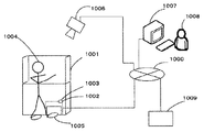
図1は、本発明の実施例のシステムの概略構成図である。
ネットワーク1000、クリーンベンチ1001、RFIDタグを付加したフットウエア1002、RFIDリーダーを収納する筺体1003、表示ランプ1004、作業者1005、監視カメラ1006、監査用モニター装置1007、監査人1008、ホストコンピュータ1009という構成である。
ここでRFIDタグとRFIDリーダーを利用した構成を採用しているが、本発明のスイッチとして、フットウエアに付加したバーコードと上記筺体に収納したバーコードリーダーを採用することも可能である。FIG. 1 is a schematic configuration diagram of a system according to an embodiment of the present invention.
Network 1000,
Here, a configuration using an RFID tag and an RFID reader is employed. However, as a switch of the present invention, a barcode attached to footwear and a barcode reader housed in the housing can be employed.
(クリーンベンチ)
1001は、薬局での混注作業等の緻密な手作業を行うクリーンベンチであり、作業者1005は立ち作業を行うものである。作業の性質上、作業台上にスイッチ類を設けることが出来ない。
そこで、ハンズフリーで操作するフットスイッチを設けるものである。(Clean bench)
Therefore, a foot switch that is operated hands-free is provided.
(RFIDタグ)
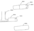
1002は、上記フットスイッチを構成するフットウエアとして採用したスリッパである。図2は、スリッパの構成、仕様態様および外観を示したものである。
2001は平面図であって、スリッパ前部の上面に左右並行して左RFIDタグ2002と右RFIDタグ2003が付加されている。付加の方法は、接着による方法、スリッパ表層に収納袋を設けて格納する方法、スリッパ表布に縫い込む方法など適宜採用可能である。左右RFIDタグの位置は、後述するRFIDリーダーとの位置関係で、スリッパサイズを考慮して適当に定めるものであり、後の段落で説明する。
ここでは、スリッパを採用したが、作業の性質や作業者の嗜好等に応じて、サンダル、靴など適当なフットウエアを採用可能である。RFIDタグを2つ付加する方式を採用しているが、一つまたは3つ以上とすることも可能である。(RFID tag)
2001 is a plan view in which a
Here, slippers are employed, but appropriate footwear such as sandals and shoes can be employed depending on the nature of the work, the operator's preference, and the like. A method of adding two RFID tags is adopted, but one or three or more can be used.
(RFIDリーダーと筺体)
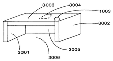
図3は、上記2つのRFIDタグを付加する方式に応じたRFIDリーダーを収納する筺体1002の構成を示したものである。左横壁2001、右横壁2002、天井2003、天井内面に固定したRFIDリーダー2004、奥壁2005、そして開口部2006という構造であり、クリーンベンチの下部領域の適当な床面に固定される。
底面部は、床面そのものであり、作業者1004は床面に沿ってすり足で開口部2006にフットウエアを装着した足を突っ込める構造となっている。
RFIDリーダー2004は、ネットワーク1000に接続し、単独で通信する機能を有するものであって、RFIDタグの読取情報をホストコンピュータ1009に送信するように構成されている。この固定位置は、筺体の左右を分割する中心線に位置付けるものとし、フットウエアの左側面を左横壁2001に沿って突っ込み動作をすると右RFIDタグと近接し、フットウエアの右側面を右横壁2002に沿って突っ込み動作をすると左RFIDタグと近接するように筺体の横幅を設定する。
表示部1004は、筺体上の作業者から視認性のよいところに設けられたLEDランプであり、RFIDリーダーの読取を検知すると所定の点灯動作をすることにより読取を通知する通知手段である。本発明の通知手段は、LEDランプに限られるものではなく液晶による読取情報の表示、スピーカーによる音声通知やブザーなど適宜採用可能である。(RFID reader and enclosure)
FIG. 3 shows a configuration of a
The bottom surface portion is the floor surface itself, and the
The
The
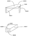
図4は、フットウエアの前面に一つのRFIDタグを付加した場合に採用する筺体1003を示した正面図と背面図である。左横壁3001、右横壁3002、天井壁3003、奥壁3004、奥壁内面に固定したRFIDリーダー3005、そして開口部3006という構造であり、クリーンベンチの下部領域の適当な床面に固定される。
左右の横壁および天井壁は、奥壁3004に向かってテーパー状に狭まるように構成されているため、作業者1005のフットウエアの突っ込み動作をガイドして、フットウエア前面のRFIDタグと奥壁内面に固定したRFIDリーダー3005と近接させる効果がある。
図3や図4に示した横壁のガイド効果により、作業者1005はRFIDリーダーの位置を意識することなく、すり足動作で横壁面にそって突っ込んでいくだけで自然にRFIDタグの読取を行わせることが出来るので、スイッチ操作に意識を煩わされることなく、手作業に集中しながら所望の機器等の制御を命令することができる。
ここでは、2つのRFIDタグを付加したフットウエアと図3に示す筺体の実施構成を採用するものとして、以下の説明を続ける。FIGS. 4A and 4B are a front view and a rear view showing a
Since the left and right lateral walls and the ceiling wall are configured to taper toward the
The guide effect of the horizontal wall shown in FIG. 3 and FIG. 4 allows the
Here, the following description is continued on the assumption that the footwear to which two RFID tags are added and the implementation configuration of the housing shown in FIG. 3 are adopted.
(監視カメラ)
監視カメラ1006は、ネットワーク1000に接続したWEBカメラである。RFIDリーダーからの読取情報を受信し、その分析・解析結果に応じてコマンドを送信するホストコンピュータ1009に制御されるものである。(Surveillance camera)
The
webカメラは、ホストコンピュータ1009の管理の下、上記クリーンベンチ上の作業領域を撮影するように撮影パラメータが調整されており、撮影した画像はネットワーク1000経由で特に図示しないデータベースに記録されるように構成されている。In the web camera, the shooting parameters are adjusted so that the work area on the clean bench is shot under the control of the
(監査)
監査用モニター1007は、ネットワークを介して上記WEBカメラの画像を映し出すように構成されている。監査人1008は、作業者1005のフットスイッチ操作に応じての通知に応じて、画像によるリモート監査をおこなう。
ここで監査人への通知は、ホストコンピュータ1009から監査人への通知メールの送信による。メールは、予め決められたフォーマットの文面で、予め登録した監査人アドレスへ、RFIDリーダーからの読取情報の分析・解析による認識に応じて、自動送信されるものである。
ここで通知の方法は上記メールに限られるものではなく、監査人の待機室に設けたスピーカー等をホストコンピュータが制御して所定の通知メッセージを発声するものであってもよい。
このようにして、作業のために常に作業者と監査人と2人を作業場に配置することによる人員的負担を、リモート監視に置き換えて、軽減させる効果がある。(audit)
The audit monitor 1007 is configured to display an image of the WEB camera via a network. The
Here, the notification to the auditor is made by sending a notification mail from the
Here, the notification method is not limited to the above e-mail, and the host computer may utter a predetermined notification message by controlling a speaker or the like provided in the auditor's waiting room.
In this way, there is an effect of reducing the burden of personnel by always placing the worker, the auditor, and two people in the work place for the work by replacing with remote monitoring.
(全体の動作の流れ)
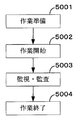
図5は、実施例に係るスイッチシステムで動作する監視および監査を示したフローチャートである。
5001は、作業準備ステップである。ここでは、左RFIDタグを作業開始、右を作業終了として設定する。
RFIDタグに対して、特に図示しないRFIDライターによって所定のID情報を書き込むものであるが、図6はその書き込みデータの一例である。書き込み年月日6001、書き込み時刻6002、作業ID6003、作業者ID6004、足区別6005、そして取付位置6006というデータ構造を採用する。
ここで、足区別6005は作業者の右足と左足の区別であり、取付位置6006は、フットウエアの右への付加か左への付加かの区別である。足区別と取付位置の組み合わせ毎に動作コマンドを割り付けてあり、その割り付けはホストコンピュータが参照可能な特に図示しない参照テーブルに格納されている。
以下の説明では、右足のフットウエア左に付加されたRFIDタグは、監視動作開始コマンドに、右足のフットウエア右に付加されたRFIDタグは監視動作終了コマンドに割り付けたものとしている。(Overall operation flow)
FIG. 5 is a flowchart illustrating monitoring and auditing that operate in the switch system according to the embodiment.
In the RFID tag, predetermined ID information is written by an RFID writer (not shown). FIG. 6 shows an example of the write data. A data structure of writing date 6001, writing
Here, the
In the following description, the RFID tag added to the left footwear of the right foot is assigned to the monitoring operation start command, and the RFID tag added to the right footwear of the right foot is assigned to the monitoring operation end command.
5002は、作業開始ステップである。作業者は、筺体の右横壁に沿って、右足を床面に沿ってすり足で筺体開口部に突っ込む。この突っ込み動作により右横壁にガイドされて、スムーズに左RFIDタグとRFIDリーダーとを接近させて、近距離無線によるフットスイッチを作動させることができる。
ここでの作動は、RFIDタグに格納されたID情報のホストコンピュータの送信であり、ホストコンピュータは予め用意しておいた足区別6005および取付位置6006と動作コマンドとの対応を示す上記参照テーブルを参照し、作業者が意図する指示を認識することができる。
The operation here is the transmission of the ID information stored in the RFID tag by the host computer. The host computer uses the above-mentioned reference table showing the correspondence between the
5003は、監視・監査ステップである。
上記右足のフットウエア左に付加されたRFIDタグのID情報の送信を受けたホストコンピュータは、監視開始コマンドを動作対象のWEBカメラへ送信すると同時に、監査人の登録アドレスへ、作業開始を通知するメールを送信する。
作業の開始を監査人に通知することができるので、作業に際して、その現場に2名を配置する必要がなくなるので、リモート監査が実現され、人的資源の節約にも貢献する。
The host computer that has received the ID information of the RFID tag attached to the left footwear of the right foot transmits a monitoring start command to the WEB camera to be operated, and simultaneously notifies the registered address of the auditor of the start of work. send mail.
Since it is possible to notify the auditor of the start of the work, it is not necessary to place two people at the site for the work, so remote auditing is realized, which contributes to saving of human resources.
5004は、作業終了ステップである。作業を終えた作業者は、終了を通知するため、左横壁にそって右足を筺体開口部に突っ込む。左横壁にガイドされて、フットウエア右に付加されたRFIDタグとRFIDリーダーとが接近し、右RFIDリーダーに格納されたID情報がホストコンピュータに送信される。ホストコンピュータは上述の参照テーブル参照し、作業者の作業終了意図を認識し、WEBカメラに対して撮影終了コマンドを送出する。
この時のWEBカメラによる撮影画像は、ホストコンピュータの動作により、作業ID、作業者ID、そして撮影の開始時刻又は終了時刻など撮影に係る時刻と関連付けた監視データとして、前述の特に図示しないデータベースに格納される。
図7は監視データのデータ構造を示したものである。監視データは、作業終了後のトレーサビリティの必要に応じて、データ項目として記録された作業IDや作業者IDあるいは撮影に係る時刻をキーに検索することが出来るので、高度なトレーサビリティを実現する効果がある。
The image taken by the WEB camera at this time is stored in the above-described database (not shown) as monitoring data associated with the shooting time such as the work ID, the worker ID, and the shooting start time or end time by the operation of the host computer. Stored.
FIG. 7 shows the data structure of the monitoring data. The monitoring data can be searched using the work ID recorded as a data item, the worker ID, or the time related to photographing as a key, as required for traceability after the work is completed. is there.
ここでは右足のフットウエアの左に付加したRFIDタグに作業開始を、右足のフットウエアに右RFIDタグに作業終了を対応づけるものとしたが、本発明はこれに限られるものではなく、左足のフットウエアの左右に付加したRFIDタグに作業開始と作業終了を対応づけるなど、左右の足のそれぞれの位置のRFIDに適宜割り当て可能である。
また、ここでは、4つのRFIDタグがあるので、作業開始と終了の通知だけでなく、照明装置のオンとオフ、調剤に使うポンプのオン・オフ、あるいは補助作業員等を呼ぶ場合のヘルプコールの送信などに割り当てて、クリーンベンチにおける手作業を中断することなく所望の動作を命令出来るマルチファンクションなスイッチシステムの構成を実現することが可能である。Here, the start of work is associated with the RFID tag attached to the left of the footwear on the right foot, and the end of work is associated with the right RFID tag on the footwear on the right foot, but the present invention is not limited to this. The start and end of work can be associated with the RFID tags added to the left and right of the footwear, for example, and can be appropriately assigned to the RFIDs at the respective positions of the left and right feet.
Since there are four RFID tags here, not only the notification of work start and end, but also a help call for calling on or off the lighting device, turning on or off the pump used for dispensing, or calling an auxiliary worker, etc. It is possible to realize a configuration of a multifunction switch system that can be assigned to the transmission of the user and can instruct a desired operation without interrupting the manual work on the clean bench.
(すり足動作)
ここですり足動作による突っ込み動作の原理について、説明する。
クリーンベンチのような作業台における作業の基本は立ち作業であるが、立ち作業中のハンズフリーのため従来型フットスイッチは、踏み込み動作を必要とするものであって、足を持ち上げるため大きな体重移動があって、手作業に悪影響を与え、フットスイッチであっても微妙な作業に際しては作業中断する必要があった。
この点、本発明の方式では、一方の足を床面に接したまま開口部へ滑り込ませればよいため、体重の上下動が極めて少なく、手作業への影響が非常に少ない。そのため、微妙な作業中においても、操作が可能なスイッチシステムとなっている。
このように手作業のバランスを失する影響が少なく、使い勝手を向上させたスイッチシステムを実現できる効果がある。(Riding foot motion)
Here, the principle of the plunging operation by the foot motion will be described.
The basis of work on a workbench such as a clean bench is standing work, but because it is hands-free during standing work, the conventional foot switch requires a stepping action and moves a lot of weight to lift the foot This adversely affects manual work, and even a foot switch needs to be interrupted for delicate work.
In this respect, in the method of the present invention, since one foot only needs to be slid into the opening while being in contact with the floor surface, there is very little up and down movement of the body weight, and there is very little influence on manual work. Therefore, the switch system can be operated even during delicate work.
In this way, there is little effect of losing the balance of manual work, and there is an effect that a switch system with improved usability can be realized.
(横壁のガイド動作)
手作業中にフットスイッチを視認することは、作業の効率を低下させるため、フットウエアを履いた足の動作を適正な位置にガイドさせることが必要である。本発明では横壁をテーパー状にすること(一つのRFIDタグの場合)、スイッチを構成する筺体の開口部の幅とフットウエアおよびRFIDタグの左右間隔(2つのRFIDタグの場合)を調整することなどで実現される。(Horizontal wall guide operation)
Viewing the foot switch during manual work reduces the work efficiency, so it is necessary to guide the movement of the foot wearing the footwear to an appropriate position. In the present invention, the lateral wall is tapered (in the case of one RFID tag), and the width of the opening of the housing constituting the switch and the left-right distance between the footwear and the RFID tag (in the case of two RFID tags) are adjusted. Etc.
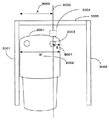
ここで2つのRFIDタグを一つのフットウエアに付加し、RFIDリーダーの位置を開口部の中心線に設定した場合の開口部の幅(図8の2A)、スリッパの幅(図8のW)、フットウエア側面とRFIDタグ付加位置の距離(図8のE)の関係について、図8を用いて説明する。
実施例に係るスリッパ2001を図3に示す筺体の左横壁3001に沿わせて突っ込み動作をした時の右RFIDタグ2003の付加位置は、筺体の左右2等分線8001と重なるように開口部の横幅(2A)およびスリッパ側面からの距離(E)を調整する。このようにすることで筺体の中心線の天井面に固定したRFIDリーダー3004とRFIDタグ2003とが近接するからである。
このようにするためには、8001で示す距離Eは「8002で示すスリッパ幅Wから開口部横幅の半分を差し引いた8003に示す長さA」に等しくなる必要がある。
すなわち、以下の等式を満たす。
E=W−A ・・・・等式1Here, when two RFID tags are added to one footwear and the position of the RFID reader is set to the center line of the opening, the width of the opening (2A in FIG. 8) and the width of the slipper (W in FIG. 8) The relationship between the distance between the footwear side surface and the RFID tag addition position (E in FIG. 8) will be described with reference to FIG.
When the
In order to do this, the distance E indicated by 8001 needs to be equal to “the length A indicated by 8003 obtained by subtracting half the width of the opening from the slipper width W indicated by 8002”.
That is, the following equation is satisfied.
E = W−A Equation 1
本発明のフットスイッチシステムは、注意深い手作業が要求される作業台において、手作業の妨げとならないフットスイッチを提供し、さらにその作業を記録し、事故や過誤が発生した場合でも、その事故や過誤に関連する画像を迅速に検索し、作業を確認できる監視データの生成、記録することができ、高度なトレーサビリティにも対応できるものである。
特に緻密な手作業が要求される作業現場に医療関係に限らず、精密機械等の組み立てなどの現場に広く利用される可能性がある。The foot switch system of the present invention provides a foot switch that does not hinder manual work on a work table that requires careful manual work, and further records the work, even if an accident or error occurs, It is possible to quickly search for images related to errors, generate and record monitoring data that can confirm the work, and cope with high traceability.
There is a possibility that it is widely used not only in the medical field but also in the field of assembling precision machines, etc., especially in the field where precise manual work is required.
1000 ネットワーク
1001 クリーンベンチ
1002 フットウエア
1003 RFIDリーダーを収納する筺体
1004 表示ランプ
1005 作業者
1006 監視カメラ
1007 監査用モニター装置
1008 監査人
1009 ホストコンピュータ1000
Claims (12)
作業台の下部床面の固定される筺体に収納されるRFIDリーダーとから構成され、
前記筺体は開口部を有し、該開口部の内壁面に前記RFIDリーダーを固定し、前記フットウエアを履いた作業者が足を前記開口部に突っ込むことにより、前記RFIDタグとRFIDリーダーを接近させることによる読取をトリガーとして予め設定した動作を起動させることを特徴とするスイッチシステム。RFID tag attached to footwear,
It consists of an RFID reader housed in a housing fixed to the lower floor surface of the workbench,
The housing has an opening, the RFID reader is fixed to an inner wall surface of the opening, and an operator wearing the footwear approaches the RFID tag and the RFID reader by pushing a foot into the opening. A switch system, wherein a preset operation is started by using a reading as a trigger.
Priority Applications (1)
| Application Number | Priority Date | Filing Date | Title |
|---|---|---|---|
| JP2010288690A JP2012123768A (en) | 2010-12-08 | 2010-12-08 | Foot switch system |
Applications Claiming Priority (1)
| Application Number | Priority Date | Filing Date | Title |
|---|---|---|---|
| JP2010288690A JP2012123768A (en) | 2010-12-08 | 2010-12-08 | Foot switch system |
Publications (1)
| Publication Number | Publication Date |
|---|---|
| JP2012123768A true JP2012123768A (en) | 2012-06-28 |
Family
ID=46505113
Family Applications (1)
| Application Number | Title | Priority Date | Filing Date |
|---|---|---|---|
| JP2010288690A Pending JP2012123768A (en) | 2010-12-08 | 2010-12-08 | Foot switch system |
Country Status (1)
| Country | Link |
|---|---|
| JP (1) | JP2012123768A (en) |
Cited By (3)
| Publication number | Priority date | Publication date | Assignee | Title |
|---|---|---|---|---|
| JP2015100318A (en) * | 2013-11-26 | 2015-06-04 | 澁谷工業株式会社 | Aseptic work system |
| JP2022027558A (en) * | 2020-07-31 | 2022-02-10 | Idec株式会社 | Control system and control program |
| JP2022172669A (en) * | 2021-05-06 | 2022-11-17 | Sbs東芝ロジスティクス株式会社 | Inspection table |
-
2010
- 2010-12-08 JP JP2010288690A patent/JP2012123768A/en active Pending
Cited By (10)
| Publication number | Priority date | Publication date | Assignee | Title |
|---|---|---|---|---|
| JP2015100318A (en) * | 2013-11-26 | 2015-06-04 | 澁谷工業株式会社 | Aseptic work system |
| WO2015079930A1 (en) * | 2013-11-26 | 2015-06-04 | 澁谷工業株式会社 | Sterile work system |
| CN105765053A (en) * | 2013-11-26 | 2016-07-13 | 涩谷工业株式会社 | Sterile work system |
| EP3075838A4 (en) * | 2013-11-26 | 2017-07-26 | Shibuya Corporation | Sterile work system |
| CN105765053B (en) * | 2013-11-26 | 2018-04-17 | 涩谷工业株式会社 | Sterile procedures system |
| US10400206B2 (en) | 2013-11-26 | 2019-09-03 | Shibuya Corporation | Sterile work system |
| JP2022027558A (en) * | 2020-07-31 | 2022-02-10 | Idec株式会社 | Control system and control program |
| JP7674942B2 (en) | 2020-07-31 | 2025-05-12 | Idec株式会社 | Control system and control program |
| JP2022172669A (en) * | 2021-05-06 | 2022-11-17 | Sbs東芝ロジスティクス株式会社 | Inspection table |
| JP7636262B2 (en) | 2021-05-06 | 2025-02-26 | Sbs東芝ロジスティクス株式会社 | Inspection table |
Similar Documents
| Publication | Publication Date | Title |
|---|---|---|
| US11654549B2 (en) | Display control device, display control method, computer program product, and communication system | |
| US9848578B2 (en) | Toy and app for remotely viewing and playing with a pet | |
| JP5776458B2 (en) | Image processing system, server, display method, and program | |
| JP2012123768A (en) | Foot switch system | |
| JP6439806B2 (en) | Robot apparatus and program | |
| KR20210099670A (en) | control room of the robot system | |
| JP2016087031A (en) | Desk system | |
| JP2008222386A (en) | Work support device | |
| JPWO2012101772A1 (en) | Elevator destination floor registration device | |
| US12525141B2 (en) | Training system for hygiene equipment | |
| CN109388471A (en) | A kind of air navigation aid and device | |
| JP2006318231A (en) | Switch system | |
| ES2832550T3 (en) | Bedding Machine Wireless Control System | |
| JP2016071676A (en) | Information processing device, portable terminal device, and information processing system | |
| JP6721023B2 (en) | Information processing device and program | |
| CN115460962A (en) | Cleaning system and method for operating the cleaning system | |
| CN110648461A (en) | Toothbrush management machine and toothbrush management method | |
| JP7366547B2 (en) | Information processing device and information processing program | |
| JP7853504B1 (en) | Product placement location display system and server for the product placement location display system | |
| JP7768184B2 (en) | Operation device and mobile robot | |
| JP2016061955A (en) | Content output device, content output method and program | |
| JP5527514B2 (en) | Dental equipment maintenance information and material ordering information notification device | |
| JP7787854B2 (en) | Vacuum cleaner management program and vacuum cleaner management system | |
| JP6721024B2 (en) | Information processing device and program | |
| US20260096031A1 (en) | Bracket for electronic device placed on vertical surface |