JP2012123734A - Switcher and method for power management of switcher - Google Patents
Switcher and method for power management of switcher Download PDFInfo
- Publication number
- JP2012123734A JP2012123734A JP2010275962A JP2010275962A JP2012123734A JP 2012123734 A JP2012123734 A JP 2012123734A JP 2010275962 A JP2010275962 A JP 2010275962A JP 2010275962 A JP2010275962 A JP 2010275962A JP 2012123734 A JP2012123734 A JP 2012123734A
- Authority
- JP
- Japan
- Prior art keywords
- power supply
- switcher
- video processing
- priority
- devices
- Prior art date
- Legal status (The legal status is an assumption and is not a legal conclusion. Google has not performed a legal analysis and makes no representation as to the accuracy of the status listed.)
- Pending
Links
- 238000000034 method Methods 0.000 title abstract description 8
- 238000007726 management method Methods 0.000 claims description 10
- 238000012544 monitoring process Methods 0.000 description 16
- 238000010586 diagram Methods 0.000 description 7
- 238000004891 communication Methods 0.000 description 4
- 230000002159 abnormal effect Effects 0.000 description 3
- 230000005856 abnormality Effects 0.000 description 3
- 230000010365 information processing Effects 0.000 description 3
- 230000007257 malfunction Effects 0.000 description 2
- 230000000694 effects Effects 0.000 description 1
- 239000011159 matrix material Substances 0.000 description 1
- 230000005236 sound signal Effects 0.000 description 1
- 230000002194 synthesizing effect Effects 0.000 description 1
Images
Landscapes
- Power Sources (AREA)
Abstract
Description
本発明は、複数の電源を有するスイッチャおよびスイッチャの電源管理方法に関する。 The present invention relates to a switcher having a plurality of power supplies and a power management method for the switchers.
業務用放送機器のスイッチャは複数のユニットおよび複数の電源で構成されている。電源は、一般的にN+1冗長構成で構成されるが、何台かの電源の不調やACケーブルの未接続などで、有効な電源の台数が減り、電源容量が不足することがある。電源容量が不足したときに、全ユニットを起動させた状態にしておくと、各ユニットに供給される電源が不安定となり、各ユニットが正常に動作できなくなる。そのため、スイッチャが完全に出力断してしまったり、外部インタフェースで電源の異常状態を伝えることができなくなったりする。 The switcher for commercial broadcasting equipment is composed of a plurality of units and a plurality of power supplies. The power supply is generally configured in an N + 1 redundant configuration, but the number of effective power supplies may be reduced and power supply capacity may be insufficient due to malfunction of some power supplies or disconnection of an AC cable. If all units are activated when the power capacity is insufficient, the power supplied to each unit becomes unstable and each unit cannot operate normally. For this reason, the switcher completely cuts off the output, or the external interface cannot communicate the abnormal state of the power supply.
電源の制御方法として、複数の情報処理装置に対して、優先順位を割り当て、停電時に優先順位の高い情報処理装置から順番に無停電電源からAC給電を行なう方法がある(例えば、特許文献1参照。)。また、複数個の処理装置を備えた装置において、それぞれの処理装置に優先順位を割り当てて、蓄電池から供給される電源の電圧が一定の値以下になったときに、優先順位の低い処理装置から電力供給を停止する方法がある(例えば、特許文献2参照。)。 As a power supply control method, there is a method in which priority is assigned to a plurality of information processing apparatuses, and AC power is supplied from an uninterruptible power supply in order from an information processing apparatus having a higher priority in the event of a power failure (see, for example, Patent Document 1). .) In addition, in an apparatus including a plurality of processing devices, when a priority is assigned to each processing device, and the voltage of the power source supplied from the storage battery falls below a certain value, the processing device with a lower priority There is a method of stopping power supply (see, for example, Patent Document 2).
特許文献1に記載された方法では、無停電電源の電源容量が不足している場合でも優先順位の低い情報処理装置への電力供給が行なわれている。また、特許文献2に記載された方法では、蓄電池の電源電圧の低下のみを検知しているので、蓄電池の異常が発生したか否かなどの電源の異常をユーザに通知することができない。
In the method described in
そこで、本発明は、電源が不調になり電源容量が不足した場合に、最小限の構成で動作を継続することができ、また、電源のステータス情報を通知することができるスイッチャおよびスイッチャの電源管理方法を提供することを目的とする。 Therefore, the present invention provides a switcher capable of continuing the operation with a minimum configuration when the power supply is malfunctioned and the power capacity is insufficient, and capable of notifying the power supply status information, and the power management of the switcher It aims to provide a method.
本発明によるスイッチャは、複数の電源装置から電力供給を受ける複数の映像処理装置を制御するスイッチャであって、映像処理装置の優先順位を管理する制御装置を備え、制御装置は、スイッチャの起動時に、最初に起動して電源装置から電源装置のステータス情報を取得し、ステータス情報から有効な電源装置の台数を判断し、優先順位と有効な電源装置の台数とに基づいて起動可能な映像処理装置を選択し、起動可能な映像処理装置だけを起動する制御装置とを備えたことを特徴とする。 The switcher according to the present invention is a switcher that controls a plurality of video processing devices that are supplied with power from a plurality of power supply devices, and includes a control device that manages the priority order of the video processing devices. A video processing apparatus that is activated first, acquires status information of the power supply from the power supply, determines the number of valid power supplies from the status information, and can be activated based on the priority order and the number of valid power supplies And a control device that activates only the image processing device that can be activated.
本発明によるスイッチャの電源管理方法は、複数の電源装置から電力供給を受ける複数の映像処理装置を制御するスイッチャの電源管理方法であって、映像処理装置の優先順位を管理し、スイッチャの起動時に、最初に起動して電源装置から電源装置のステータス情報を取得し、ステータス情報から有効な電源装置の台数を判断し、優先順位と有効な電源装置の台数とに基づいて起動可能な映像処理装置を選択し、起動可能な映像処理装置だけを起動させることを特徴とする。 A power management method for a switcher according to the present invention is a power management method for a switcher that controls a plurality of video processing devices that receive power supply from a plurality of power supply devices, manages the priority order of the video processing devices, and activates the switcher. A video processing apparatus that is activated first, acquires status information of the power supply from the power supply, determines the number of valid power supplies from the status information, and can be activated based on the priority order and the number of valid power supplies And only the startable video processing apparatus is started.
本発明によるスイッチャの電源管理方法は、複数の電源装置から電力供給を受ける複数の映像処理装置を制御するスイッチャの電源管理方法であって、映像処理装置の優先順位を管理し、スイッチャの起動後、電源装置から供給される電源電圧が予め設定された閾値を下回ったときに、スイッチャの最終出力に使用されていない映像処理装置に最も低い優先度を設定し、スイッチャの最終出力に使用されている映像処理装置に優先順位に基づいた優先度を設定し、優先度の低い映像処理装置から順に回路を停止させることを特徴とする。 A power management method for a switcher according to the present invention is a power management method for a switcher that controls a plurality of video processing devices that are supplied with power from a plurality of power supply devices, manages the priority of the video processing devices, and activates the switcher When the power supply voltage supplied from the power supply device falls below a preset threshold, the lowest priority is set for the video processing device that is not used for the final output of the switcher and is used for the final output of the switcher. A priority based on the priority order is set in the video processing apparatus, and the circuit is stopped in order from the video processing apparatus having the lowest priority.
本発明によれば、電源が不調になり電源容量が不足した場合に、最小限の構成で動作することができる。また、最小限の構成で動作可能であるので、電源のアラーム情報を通知したり、スイッチャを完全に出力断させないようにしたりできる。 According to the present invention, when the power supply is malfunctioning and the power supply capacity is insufficient, it is possible to operate with a minimum configuration. Further, since it can operate with a minimum configuration, it is possible to notify power supply alarm information and prevent the switcher from completely shutting off the output.
実施形態1.
以下、本発明の第1の実施形態を図面を参照して説明する。
A first embodiment of the present invention will be described below with reference to the drawings.
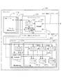
図1は、本発明が適用されるスイッチャの第1の実施形態の構成例を示すブロック図である。スイッチャ100は、電源ユニット111〜113と、コントロールユニット120と、ユニット200とを備える。なお、図1には、3つの電源ユニット111〜113が例示されているが、電源ユニットはいくつあってもよい。また、ユニット200は複数あってもよい。
FIG. 1 is a block diagram showing a configuration example of a first embodiment of a switcher to which the present invention is applied. The
電源ユニット111〜113は、AC電流をDC電流に変換し、ユニット200にDC電流を供給する電源である。電源ユニット111〜113は、N+1冗長構成で構成される。N+1冗長構成は、複数台の電源ユニットのうち、例えば、1台を予備系とし、残りを運用系とする構成である。なお、電源ユニット111〜113は、N+1冗長構成以外で構成されていてもよい。
The
電源ユニット111〜113は、通信インタフェース161でコントロールユニット120と接続されている。
The
電源ユニット111〜113は、通信インタフェース161を介して、コントロールユニット120に電源ユニットのステータス情報を通知する。電源ユニットのステータス情報は、電源ユニット111〜113のそれぞれのアラーム情報、電源ON/OFF情報などを含む。
The
コントロールユニット120は、制御回路121と、有効電源台数チェック回路122DC―DCコンバータ123を含む。また、コントロールユニット120は、イーサネット(登録商標)などの外部インタフェース153で、スイッチャ100の外部に設置された端末(以下、操作端末という。)と接続可能である。また、コントロールユニット120は、制御インタフェース162でユニット200と接続されている。
The
有効電源台数チェック回路122は、通信インタフェース161を介して電源ユニット111〜113と通信し、電源ユニット111〜113がスイッチャ100に接続されているか否かを確認し、接続されている電源ユニットからステータス情報を取得する。有効電源台数チェック回路122は、電源ユニットの接続状態および取得したステータス情報から、有効な電源台数を判断する。また、有効電源台数チェック回路122は、電源ユニットのステータス情報を制御回路121に出力する。
The valid power supply
制御回路121は、有効電源台数チェック回路122から入力されたステータス情報を外部インタフェース163を介して、操作端末に出力する。また、操作端末から入力されたユニット200の優先順位を保持する。優先順位は、ユニット200が複数ある場合に、電源ユニットが不調になり電源容量が不足したときに、どのユニットから動作を停止させるかを判断するための情報である。
The
制御用回路121は、制御インタフェース162を介して、ユニット200と通信し、ユニット200を制御する。
The
ユニット200は、電源制御回路210と、メイン回路220とを含む。ユニット200は、コントロールユニット120によって制御されるユニットであって、MTX(Matrix Switcher)やMK(Mixer and Keyer)やDVE(Digital Video Effect)などのユニットである。
電源制御回路210は、制御/DC電源監視回路211とDC―DCコンバータ212とを含む。
The power
制御/DC電源監視回路211は、制御インタフェース162を介して、コントロールユニット120と通信を行う。また、制御/DC電源監視回路211は、メイン回路220のDC―DCコンバータ222a〜222cを制御する。
The control / DC power
DC―DCコンバータ212は、DC電源から供給されるDC電圧を適当な電圧値に変換して制御/DC電源監視回路211に供給する回路である。
The DC-
メイン回路220は、サブ回路221a〜221cとDC―DCコンバータ222a〜222cとを含む。
The
サブ回路221a〜221cは、メイン回路220を構成する回路であって、ユニット200の種類に応じた機能を供える。また、図2では、3つのサブ回路221a〜221cが例示されているが、サブ回路は3つに限定されない。
The
DC―DCコンバータ222a〜222cは、DC電源から供給されるDC電圧を適当な電圧値に変換してサブ回路221a〜221cに供給する回路である。DC―DCコンバータ222a〜222cは、制御/DC電源監視回路211の指示に基づいて、サブ回路への電力供給のON/OFFを切り替える。
The DC-
制御/DC電源監視回路211は、コントロールユニット120から入力された優先度を保持する。また、制御/DC電源監視回路211は、電源ユニット111〜113から入力されるDC電源の電源電圧を監視し、DC電源の電源電圧が予め設定された閾値を下回った場合は、電源ユニットに異常があったと判断する。また、電源ユニットが異常と判断した場合に優先度が低いときは、ユニットの動作状態に応じて、DC−DC回路222a〜222cのON/OFFを制御する。
The control / DC power
次に、本実施形態の動作について説明する。 Next, the operation of this embodiment will be described.
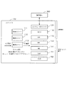
図2は、スイッチャ100の構成の一例を示すブロック図である。
FIG. 2 is a block diagram illustrating an example of the configuration of the
スイッチャ100は、電源ユニット111〜113とコントロールユニット120とを備える。また、電源ユニット111〜113は、2+1冗長構成で構成されている。また、コントロールユニット120は、操作端末300と接続されている。
The
スイッチャ100は、MTX130、MK141〜143およびDVE151〜152のユニットを備える。図2では、3つのMK141〜143が例示されているが、MKはいくつあってもよい。また、図2では、2つのDVE151〜152が例示されているが、DVEはいくつあってもよい。また、各ユニットは、ユニット200の構成を有する。
The
MTX130は、入出力信号の切り替え処理を行なうユニットである。MTX130は、SDI信号を入力し、SDI信号に含まれる映像信号や音声信号をMK141〜143、DVE151〜152の各々に出力する。また、MK141〜143、DVE151〜152の出力信号を入力信号として入力する。また、MTX130は、入力信号をMK141〜143、DVE151〜152のどれに出力するかを自在に切り替えることができる。入出力信号の切り替えは、操作端末からコントロールユニット120を介してMTX130に設定することができる。
The
MK141〜143は、映像または音声の合成や文字スーパの合成を行なうユニットである。
DVE151〜152は、映像の拡大縮小、並行移動、回転移動、変形などを行なうユニットである。
The
次に、MK143の出力を最終出力とした場合のスイッチャ100の起動時の動作について説明する。
Next, an operation at the time of starting the
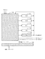
図3は、MK143の出力を最終出力とした場合の信号の流れを示す説明図である。
FIG. 3 is an explanatory diagram showing the signal flow when the output of the
図3に示すようにMK143の出力を最終出力とした場合は、コントロールユニット120と、MTX130およびMK143は、最終出力を出力させるために必ず必要となる。この場合、MTX130およびMK143は、常に起動させる必要があるユニットであるので、ユニット200で示される構成を有していないMTXおよびMKであってもよい。ここでは、MTX143およびMK143がユニット200で示される構成を有していない場合について説明する。
As shown in FIG. 3, when the output of the
スイッチャ100に電源が投入され、電源ユニット111〜113が起動してDC電源が安定すると、コントロールユニット120、MTX130およびMK143が起動する。また、MK141〜142、およびDVE151〜152の電源制御回路210が起動する。
When the
次に、コントロールユニット120の有効電源台数チェック回路122は、電源ユニット111〜113のそれぞれがスイッチャ100に接続されているか否かを確認する。有効電源台数チェック回路122は、接続されている電源ユニットからステータス情報を取得し、有効な電源ユニットの台数(以下、有効電源台数という。)を判断する。有効電源台数チェック回路122は、ステータス情報と有効電源台数の情報とを制御回路121に出力する。制御回路121は、入力されたステータス情報を外部インタフェース163に出力する。
Next, the effective power supply
制御回路121は、有効電源台数およびMK141〜142、およびDVE151〜152の各ユニットの優先順位に基づいて起動可能なユニットを判断し、起動可能なユニットの電源制御回路210に対して、メイン回路220のDC−DC回路222a〜222cをONするように指示を出す。
The
次に、MK143の出力を最終出力とした場合のスイッチャ100の起動後の動作について説明する。
Next, an operation after starting the
コントロールユニット120の制御回路121は、各ユニットの出力が最終出力で使用されているか否か、つまり、MK141〜142、DVE151〜152の出力がMK143の入力に選択されているか否かの情報(以下、出力設定情報という。)を、制御インタフェース162を介してMTX130から取得する。
The
制御回路121は、出力設定情報に基づいて出力が最終出力で使用されていないユニットを判断し、出力が最終出力で使用されていないと判断したユニットの制御/DC電源監視回路211に対して、低い優先度を設定する。
The
出力が最終出力で使用されていないユニットの制御/DC電源監視回路211は、DC電源の電源電圧が予め設定された閾値を下回っていて、且つ、コントロールユニット120によって設定された優先度が低い場合は、電源ユニットの電源負荷を下げるために、サブ回路221a〜221cのDC−DC回路222a〜222cをオフにしてユニットの動作を停止させる。このとき、制御/DC電源監視回路211は、電源異常によりユニットの動作を停止させたことをコントロールユニット120を介して、操作端末300に通知する。また、コントロールユニット120は、以降、停止させたユニットへの操作を操作端末300から受け付けないようにする。
The control / DC power
制御回路121は、出力が最終出力で使用されていないユニットの動作を停止させてもDC電源の電圧が回復しない場合は、ユニットの優先順位に基づいて、出力が最終出力で使用されているユニットのうち、最も優先順位が低いユニットの制御/DC電源監視回路211に対して、低い優先度を設定する。
In the case where the voltage of the DC power source does not recover even when the operation of the unit whose output is not used for the final output is stopped, the
出力が最終出力で使用されているユニットの制御/DC電源監視回路211は、DC電源の電源電圧が予め設定された閾値を下回っていて、且つ、コントロールユニット120によって設定された優先度が低い場合は、電源ユニットの電源負荷を下げるために、サブ回路221a〜221cのDC−DC回路222a〜222cをオフにしてユニットの動作を停止させる。このとき、出力が最終出力で使用されているユニットは、主要な処理(映像の合成処理や出力処理など。)を継続して動作させることが望ましい。そのため、制御/DC電源監視回路211は、優先度の低いサブ回路のDC−DC回路をオフにして動作を停止させる。
The control / DC power
例えば、サブ回路221aがユニットの主要な処理を行なう回路であって、サブ回路221b、221cがステータス通知やプレビュー処理などの主要な処理以外の処理を行う回路であった場合は、サブ回路221b、221cの優先度は低い。そのため、制御/DC電源監視回路211は、サブ回路221b、221cを先に停止させ、サブ回路221aの動作を継続させる。サブ回路221b、221cの動作を停止させてもDC電源の電圧が回復しないときは、サブ回路221aの動作を停止させる。このとき、サブ回路221aの動作を停止させずに、継続させてもよい。
For example, when the
制御/DC電源監視回路211は、電源異常によりメイン回路220のサブ回路の動作を停止させたことをコントロールユニット120を介して、操作端末300に通知する。また、コントロールユニット120は、以降、停止させたユニットのサブ回路への操作を操作端末300から受け付けないようにする。
The control / DC power
出力が最終出力で使用されているユニットのうち、最も優先順位が低いユニットの動作を停止させてもDC電源の電圧が回復しない場合は、次に優先順位の低いユニットに対して、同様の処理を繰り返す。 If the DC power supply voltage does not recover even when the operation of the unit with the lowest priority among the units whose output is used as the final output is stopped, the same processing is performed for the unit with the next lowest priority. repeat.
以上に説明したように、スイッチャ100の起動時または起動中に複数ある電源ユニットのうちの何台かの電源ユニットが不調になり電源容量が不足した場合に、完全に出力断とならずに、最小限の構成で動作を継続させることができる。また、コントロールユニット120は常に起動しているので、操作端末300に電源ユニットのステータス情報を通知することができる。
As described above, when some or all of the power supply units out of order when the
また、優先順位は操作端末300から任意に設定できるので、スイッチャ100の電源投入時に、必要最小限のユニットを起動させたり、DVE151〜152以外を起動させたりすることができる。
Further, since the priority order can be arbitrarily set from the
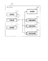
図4は、本発明によるスイッチャの主要部を示すブロック図である。図4に示すように、複数の電源装置111〜11n(実施形態では、電源ユニット111〜113で実現される。)から電力供給を受ける複数の映像処理装置131〜13n(実施形態では、ユニット200で実現される。)を制御するスイッチャ10(実施形態では、スイッチャ100で実現される。)であって、映像処理装置131〜13nの優先順位を管理する制御装置12(実施形態では、コントロールユニット120で実現される。)を備え、制御装置は、スイッチャの起動時に、最初に起動して電源装置111〜11nから電源装置111〜11nのステータス情報を取得し、ステータス情報から有効な電源装置の台数を判断し、優先順位と有効な電源装置の台数とに基づいて起動可能な映像処理装置を選択し、起動可能な映像処理装置だけを起動する制御装置とを備えたことを特徴とする。
FIG. 4 is a block diagram showing the main part of the switcher according to the present invention. As shown in FIG. 4, a plurality of
上記の実施形態には、以下のようなスイッチャも開示されている。 In the above embodiment, the following switcher is also disclosed.
(1)制御装置12は、スイッチャ10の起動後、電源装置111〜11nから供給される電源電圧が予め設定された閾値を下回ったときに、スイッチャ10の最終出力に使用されていない映像処理装置に最も低い優先度を設定し、スイッチャの最終出力に使用されている映像処理装置は優先順位に基づいて優先度を設定し、優先度の低い映像処理装置から順に回路を停止させるスイッチャ。
(1) After the
(2)映像処理装置131〜13nは、複数の回路(実施形態では、サブ回路221a〜221cで実現される。)を備え、電源装置111〜11nから供給される電源電圧が予め設定された閾値を下回ったときに、制御装置12から設定された優先度が低い場合は、動作状態に応じて回路に優先度を設定し、優先度の低い回路の電力供給を停止させるスイッチャ。
(2)
(3)制御装置12は、電源装置111〜11nから電源装置111〜11nのステータス情報を取得すると、外部インタフェース(実施形態では、外部インタフェース163で実現される。)を介して操作端末(実施形態では、操作端末300で実現される。)に電源装置111〜11nのステータス情報を送信する。
(3)
10、100 スイッチャ
111〜11n 電源装置
12 制御装置
131〜13n 映像処理装置
111、112、113 電源ユニット
120 コントロールユニット
121 制御回路
122 有効電源台数チェック回路
123、212、222a、222b、222c DC―DCコンバータ
130 MTX
141、142、143 MK
151、152 DVE
161 通信インタフェース
162 制御インタフェース
163 外部インタフェース
200 ユニット
210 電源制御回路
211 制御/DC電源監視回路
220 メイン回路
221a、221b、221c サブ回路
300 操作端末
10, 100
141, 142, 143 MK
151, 152 DVE
161 communication interface 162 control interface 163
Claims (6)
前記映像処理装置の優先順位を管理する制御装置を備え、
前記制御装置は、前記スイッチャの起動時に、最初に起動して前記電源装置から前記電源装置のステータス情報を取得し、前記ステータス情報から有効な電源装置の台数を判断し、前記優先順位と前記有効な電源装置の台数とに基づいて起動可能な映像処理装置を選択し、前記起動可能な映像処理装置だけを起動する制御装置とを備えた
ことを特徴とするスイッチャ。 A switcher for controlling a plurality of video processing devices receiving power supply from a plurality of power supply devices,
A control device for managing the priority of the video processing device;
When the switcher is activated, the control device is activated first, acquires the status information of the power supply device from the power supply device, determines the number of valid power supply devices from the status information, and determines the priority and the effective A switcher comprising: a control device that selects a startable video processing device based on the number of power supply devices and starts only the startable video processing device.
請求項1に記載のスイッチャ。 When the power supply voltage supplied from the power supply device falls below a preset threshold after the switcher is activated, the control device sets the lowest priority to the video processing device that is not used for the final output of the switcher. 2. The switcher according to claim 1, wherein a priority is set for the video processing device used for the final output of the switcher based on the priority order, and the circuit is stopped in order from the video processing device with the lowest priority.
請求項1または請求項2に記載のスイッチャ。 The video processing device includes a plurality of circuits, and when the power supply voltage supplied from the power supply device falls below a preset threshold value and the priority set by the control device is low, the video processing device The switcher according to claim 1, wherein priority is set for the circuit, and power supply to the circuit with low priority is stopped.
請求項1から請求項3のいずれか1項に記載のスイッチャ。 The switcher according to any one of claims 1 to 3, wherein when the control device acquires the status information of the power supply device from the power supply device, the control device transmits the status information of the power supply device to the operation terminal via an external interface. .
映像処理装置の優先順位を管理し、スイッチャの起動時に、最初に起動して電源装置から電源装置のステータス情報を取得し、ステータス情報から有効な電源装置の台数を判断し、前記優先順位と前記有効な電源装置の台数とに基づいて起動可能な映像処理装置を選択し、前記起動可能な映像処理装置だけを起動させる
ことを特徴とするスイッチャの電源管理方法。 A power management method for a switcher for controlling a plurality of video processing devices receiving power supply from a plurality of power devices,
The priority order of the video processing devices is managed, and when the switcher is started, the power supply device is first activated to obtain the status information of the power supply device, and the number of valid power supply devices is determined from the status information. A switcher power management method comprising: selecting a video processing device that can be activated based on the number of effective power supply devices and starting only the video processing device that can be activated.
映像処理装置の優先順位を管理し、スイッチャの起動後、電源装置から供給される電源電圧が予め設定された閾値を下回ったときに、スイッチャの最終出力に使用されていない映像処理装置に最も低い優先度を設定し、スイッチャの最終出力に使用されている映像処理装置に前記優先順位に基づいた優先度を設定し、優先度の低い映像処理装置から順に回路を停止させる
ことを特徴とするスイッチャの電源管理方法。 A power management method for a switcher for controlling a plurality of video processing devices receiving power supply from a plurality of power devices,
Manages the priority of video processing devices, and is the lowest for video processing devices that are not used for the final output of the switcher when the power supply voltage supplied from the power supply device falls below a preset threshold after the switcher is started A priority is set, a priority based on the priority is set for a video processing device used for the final output of the switcher, and the circuit is stopped in order from the video processing device with the lowest priority. Power management method.
Priority Applications (1)
| Application Number | Priority Date | Filing Date | Title |
|---|---|---|---|
| JP2010275962A JP2012123734A (en) | 2010-12-10 | 2010-12-10 | Switcher and method for power management of switcher |
Applications Claiming Priority (1)
| Application Number | Priority Date | Filing Date | Title |
|---|---|---|---|
| JP2010275962A JP2012123734A (en) | 2010-12-10 | 2010-12-10 | Switcher and method for power management of switcher |
Publications (1)
| Publication Number | Publication Date |
|---|---|
| JP2012123734A true JP2012123734A (en) | 2012-06-28 |
Family
ID=46505082
Family Applications (1)
| Application Number | Title | Priority Date | Filing Date |
|---|---|---|---|
| JP2010275962A Pending JP2012123734A (en) | 2010-12-10 | 2010-12-10 | Switcher and method for power management of switcher |
Country Status (1)
| Country | Link |
|---|---|
| JP (1) | JP2012123734A (en) |
Cited By (3)
| Publication number | Priority date | Publication date | Assignee | Title |
|---|---|---|---|---|
| CN108319357A (en) * | 2017-01-18 | 2018-07-24 | 广达电脑股份有限公司 | Method for turning off power of multiple active elements of system and server system |
| JP2018139099A (en) * | 2017-01-05 | 2018-09-06 | 新唐科技股▲ふん▼有限公司 | Apparatus for adjusting power drawn out from external power source by electronic apparatus, system, method and computer program product |
| JP2018169731A (en) * | 2017-03-29 | 2018-11-01 | 東芝メモリ株式会社 | Semiconductor device and control method thereof |
-
2010
- 2010-12-10 JP JP2010275962A patent/JP2012123734A/en active Pending
Cited By (4)
| Publication number | Priority date | Publication date | Assignee | Title |
|---|---|---|---|---|
| JP2018139099A (en) * | 2017-01-05 | 2018-09-06 | 新唐科技股▲ふん▼有限公司 | Apparatus for adjusting power drawn out from external power source by electronic apparatus, system, method and computer program product |
| CN108319357A (en) * | 2017-01-18 | 2018-07-24 | 广达电脑股份有限公司 | Method for turning off power of multiple active elements of system and server system |
| JP2018116680A (en) * | 2017-01-18 | 2018-07-26 | 廣達電腦股▲ふん▼有限公司 | Power supply unit (PSU) management |
| JP2018169731A (en) * | 2017-03-29 | 2018-11-01 | 東芝メモリ株式会社 | Semiconductor device and control method thereof |
Similar Documents
| Publication | Publication Date | Title |
|---|---|---|
| US8782449B2 (en) | Power supply system with a plurality of power supply units capable of powering a plurality of load units depending on the type and operation state of each load unit | |
| EP3318004B1 (en) | Power providing device and method, power receiving device | |
| US9223394B2 (en) | Rack and power control method thereof | |
| JP6348662B2 (en) | Uninterruptible power system | |
| US8484491B2 (en) | Power supply apparatus and power supply control method | |
| US7723866B2 (en) | Power backup system | |
| JP6649239B2 (en) | Uninterruptible power supply system | |
| TW201407919A (en) | Power system with combination of active current sharing and droop current sharing and power system assembly using the same | |
| JP2012123734A (en) | Switcher and method for power management of switcher | |
| JP5088049B2 (en) | Power system | |
| JP2008278666A (en) | Uninterruptible power supply device | |
| JP2012089048A (en) | Information processing apparatus, control method and control device | |
| JP2010206919A (en) | Backup power supply device, backup power supply system, and power supply switching method | |
| JP7255249B2 (en) | Power supply circuit and electronic device | |
| JP4775717B2 (en) | Power supply system, internal circuit driving method, and program thereof | |
| JP6175815B2 (en) | Multiple power supply apparatus, control method for multiple power supply apparatus, and program | |
| JP5012741B2 (en) | Power supply device, power supply method, power supply control program, and power supply system | |
| JP2017041919A (en) | Power conversion system | |
| JP2011060189A (en) | System and method for coping with power discontinuity | |
| JP4266978B2 (en) | Telephone exchange device and power consumption suppression method thereof | |
| JP2017021686A (en) | Peripheral device, peripheral device system, and control method of peripheral device | |
| JP2015126591A (en) | Uninterruptible power system | |
| JP2010509902A (en) | UPS automatic monitoring system and automatic recovery method using the same | |
| JP2007124783A (en) | Uninterruptible power supply and battery unit | |
| JP2000102164A (en) | Power supply |