JP2012123293A - Stationary inductance electrical appliance and low frequency sound absorbing wall - Google Patents
Stationary inductance electrical appliance and low frequency sound absorbing wall Download PDFInfo
- Publication number
- JP2012123293A JP2012123293A JP2010275517A JP2010275517A JP2012123293A JP 2012123293 A JP2012123293 A JP 2012123293A JP 2010275517 A JP2010275517 A JP 2010275517A JP 2010275517 A JP2010275517 A JP 2010275517A JP 2012123293 A JP2012123293 A JP 2012123293A
- Authority
- JP
- Japan
- Prior art keywords
- sound absorbing
- sound
- opening
- frequency
- noise
- Prior art date
- Legal status (The legal status is an assumption and is not a legal conclusion. Google has not performed a legal analysis and makes no representation as to the accuracy of the status listed.)
- Granted
Links
Images


Abstract
Description
本発明の実施形態は、変圧器やリアクトルに代表される静止誘導電器と、静止誘導電器を覆ってその静止誘導電器から発生する低周波騒音を低減する低周波吸音壁に関する。 Embodiments of the present invention relate to a static induction electric device represented by a transformer and a reactor, and a low frequency sound absorbing wall that covers the static induction electric appliance and reduces low frequency noise generated from the static induction electric appliance.
変圧器やリアクトルなどの静止誘導電器においては、静止誘導電器本体から電源周波数に基づく騒音が発生することが知られており、特に100〜200Hzの低周波数領域の騒音が問題となることが多い。低周波数領域の騒音を低減する手段としては、一般に鋼板を用いて構成された防音タンク等の防音構造物を、静止誘導電器本体を包囲するように設置することが多い。 In static induction appliances such as transformers and reactors, it is known that noise based on the power supply frequency is generated from the main body of the static induction appliance, and in particular, noise in a low frequency region of 100 to 200 Hz is often a problem. As a means for reducing the noise in the low frequency region, a soundproof structure such as a soundproof tank generally made of a steel plate is often installed so as to surround the stationary induction main body.
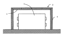
図11は、一般的な低騒音化構造を有する静止誘導電器の概略構成を示す立断面図であり、図11を参照して、静止誘導電器の一般的な騒音低減手段について説明する。 FIG. 11 is a vertical sectional view showing a schematic configuration of a static induction electric device having a general noise reduction structure, and a general noise reduction means of the static induction electric device will be described with reference to FIG.
防音構造物2は、静止誘導電器本体1の周囲を囲むように設けられた防音構造物であって、鋼板等の金属製のパネルからなる遮音壁4で静止誘導電器本体1を覆うように組み合わせて構成されている。 The soundproof structure 2 is a soundproof structure provided so as to surround the periphery of the stationary induction electric body 1 and is combined so as to cover the stationary induction electric body 1 with a sound insulating wall 4 made of a metal panel such as a steel plate. It is configured.
また、多孔質吸音材3は、防音構造物2の内部において、ビルドアップによる騒音レベルの増加を防ぐため、遮音壁4の内面に設置されている。 The porous sound absorbing material 3 is installed on the inner surface of the sound insulating wall 4 in order to prevent an increase in noise level due to build-up inside the soundproof structure 2.
このように構成することにより、静止誘導電器本体1から発生した騒音は、防音構造物2を構成する遮音壁4の透過損失および多孔質吸音材3による吸音効果により低減されるので、静止誘導電器の騒音を低減させることができる。 With this configuration, noise generated from the static induction electric body 1 is reduced by the transmission loss of the sound insulating wall 4 constituting the soundproof structure 2 and the sound absorption effect by the porous sound absorbing material 3. Noise can be reduced.
上記のように、防音構造物2の内部において、ビルドアップによる騒音レベルの増加を防ぐために用いられる多孔質吸音材3およびその構成方法に対して、性能向上を目的とした様々な提案が行われている。 As described above, various proposals for improving the performance of the porous sound absorbing material 3 used for preventing an increase in the noise level due to build-up and the method for constructing the same are made in the soundproof structure 2. ing.
例えば、静止誘導電器から発生する代表的な騒音の特徴周波数域である100Hz〜200Hzの低周波数領域の騒音に対する吸音材の吸音特性を向上させるために、皮膜とグラスウール等の多孔質層を組み合わせた低周波吸音部材が用いられることが多い。 For example, a film and a porous layer such as glass wool are combined in order to improve the sound absorption characteristics of the sound absorbing material with respect to noise in a low frequency range of 100 Hz to 200 Hz, which is a characteristic frequency range of typical noise generated from a static induction appliance. Low frequency sound absorbing members are often used.
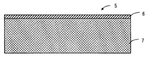
上記の構成について、図12を参照して説明する。図12は、低周波吸音部材の構成を示す縦断面図であり、図において、低周波吸音部材5は、厚さが50μm程度で面密度が0.68〜0.78kg/m2、または、1.75〜1.85kg/m2のシリコン系の樹脂からなる皮膜6と、皮膜6の背面側に積層されるグラスウール(密度32kg/m3)からなる多孔質体層7とを備え、低周波数領域の騒音に対して効果が得られるよう構成されている。
The above configuration will be described with reference to FIG. FIG. 12 is a longitudinal sectional view showing the configuration of the low frequency sound absorbing member. In the figure, the low frequency
このように構成された低周波吸音部材5を、静止誘導電器本体1を収納する鋼板等の金属製の遮音壁4の内面、または静止誘導電器本体1が設置された床面に配置する。
The low-frequency sound-absorbing
このような構成の静止誘導電器の防音構造においては、皮膜6の面密度を上記のようにすることにより、低周波吸音部材5の吸音率のピーク周波数を低周波数領域側にシフトすることができるとともに、200Hz付近の低周波数領域における吸音率も向上させることができる。
In the soundproof structure of the static induction appliance having such a configuration, the peak frequency of the sound absorption coefficient of the low frequency
また、400Hz以下、特に120Hz以下の低周波数領域の騒音に対する吸音効果を向上させるため、多孔質吸音板および繊維状吸音材等を組み合わせた低周波吸音部材が用いられることもある。 Moreover, in order to improve the sound absorption effect with respect to noise in a low frequency range of 400 Hz or less, particularly 120 Hz or less, a low frequency sound absorbing member in which a porous sound absorbing plate and a fibrous sound absorbing material are combined may be used.
この場合に用いられている低周波吸音部材の構成について、図13を参照して説明する。 The configuration of the low-frequency sound absorbing member used in this case will be described with reference to FIG.
発生音源側(図の上側)から厚さ3mm〜12mmの金属多孔質吸音板8、厚さ30mm〜100mmの繊維状吸音材9、厚さ30mm〜100mmの空気層10および厚さ30mm〜100mmの繊維状吸音材9が順に配置されている。また、繊維状吸音材9の背面側には図示しない遮音板が更に配置されることもある。
A porous metal
以上のような構成の吸音構造においては、金属多孔質吸音板8と繊維状吸音材9とを組み合わせることにより、それぞれ単体で用いる場合よりも、高い吸音率を得ることができるとともに、静止誘導電器本体1から発生する騒音の特徴周波数である120Hz以下の低周波数領域での高い吸音率を得ることが可能となる。
In the sound absorbing structure having the above-described configuration, by combining the metal porous
また、消音器の原理を応用した防音壁を用いた静止誘導電器の例として、例えば、連続気泡硬質発泡材からなる棒状の吸音板をその軸方向の中心部にその長手方向に沿う凸部曲面を有する形状に形成し、この吸音板の幅方向の両端部に遮音板の両端部に合わせて防音筒を構成し、この防音筒の吸音板側を騒音発生源側に向けると共に、この防音筒を互いに密接あるいは所定の間隔をおいて配列した防音壁を用いた静止誘導電器がある。 In addition, as an example of a static induction appliance using a soundproof wall that applies the principle of a silencer, for example, a rod-shaped sound absorbing plate made of open-celled hard foam material has a convex curved surface along its longitudinal direction at its axial center. The sound absorbing plate is formed at both ends of the sound absorbing plate in the width direction according to the both ends of the sound insulating plate, the sound absorbing plate side of the sound insulating tube is directed to the noise generating source side, and the sound insulating tube There is a static induction electric device using soundproof walls arranged in close proximity to each other or at a predetermined interval.
ここで用いられている防音壁の構成について、図14および図15を参照して説明する。 The configuration of the sound barrier used here will be described with reference to FIGS. 14 and 15.
図において、11は防音壁、12は防音筒、13aは防音筒を構成するアルミニウム発泡材からなる吸音板、13bはアルミニウム平板からなる遮音板である。 In the figure, 11 is a soundproof wall, 12 is a soundproof tube, 13a is a sound absorbing plate made of an aluminum foam material constituting the soundproof tube, and 13b is a sound insulating plate made of an aluminum flat plate.
防音壁11を構成する防音筒12は、幅方向の中心部にその長手方向に沿う凸曲面部を有する形状に形成され、かつ連続気泡硬質発泡材からなる吸音板13aの両端部と遮音板13bを結合して吸音板13aと遮音板13bとで空洞部14を形成した筒状構成になっている。
The
この吸音板13aにおける音波の入射位置によって防音筒12の空洞部14の空気層の厚さに対応する周波数の音波を高吸音率で吸音することができる。
The sound wave having a frequency corresponding to the thickness of the air layer of the
このような防音筒は広範囲の周波数を有する音波に対して高吸音性能を有することになる。また、上記したように吸音板13aは凸曲面部を有する形状に形成されているので、この吸音板に対して任意の角度をなして入射する音波を高吸音率で吸音することが可能である。
Such a soundproof cylinder has high sound absorption performance for sound waves having a wide range of frequencies. Further, as described above, since the
以上は、いずれも、静止誘導電器の騒音で問題となる低周波数領域の吸音効果を高めることを目的としている。 All of the above aims to enhance the sound absorption effect in the low frequency region, which is a problem due to the noise of static induction appliances.
ここで、吸音材のみの組合せで低周波領域の騒音低減を行おうとした場合、例えばグラスウールを用いた場合は、その吸音特性の問題から、空気層を大きくとる必要があるなど、どうしても全体的な厚みが大きくなってしまい、現実的な機器に適用する場合に支障となる場合が多い。 Here, when trying to reduce the noise in the low frequency region by combining only the sound absorbing material, for example, when using glass wool, it is necessary to take a large air layer due to the problem of the sound absorbing characteristics, and the whole In many cases, the thickness becomes large, which is a problem when applied to realistic equipment.
ここで、特定の周波数に対して効果を発揮する代表的な消音装置のひとつとして、共鳴型消音装置について説明する。 Here, a resonance type silencer will be described as one of typical silencers that exert an effect on a specific frequency.
共鳴型消音装置のひとつであるヘルムホルツ型消音器の共鳴周波数fは、(1)式で求められる(但し開口部の形状が丸穴の場合)。 The resonance frequency f of the Helmholtz type silencer, which is one of the resonance type silencers, is obtained by the equation (1) (provided that the shape of the opening is a round hole).
f={c/(2π)}√[S/{V(L+0.8d)}] … (1)
ここで、cは媒質の音速、Sは消音器の開口面積、Vは消音器の容積、Lは開口部の長さ(首長さ)、dは開口部の直径である。
f = {c / (2π)} √ [S / {V (L + 0.8d)}] (1)
Here, c is the sound velocity of the medium, S is the opening area of the silencer, V is the volume of the silencer, L is the length of the opening (neck length), and d is the diameter of the opening.
例えば、静止誘導電器の代表的な機器として、変圧器を例に挙げると、発生する音の主要周波数は電源周波数の2倍の周波数およびその倍調波成分であることから、発生する騒音の特徴周波数は既知の値となる。したがって、消音器の共鳴周波数を予め発生騒音の特徴周波数に一致させるように構成することにより、消音器による騒音の低減が可能となる。 For example, when a transformer is taken as an example of a typical static induction device, the main frequency of the generated sound is twice the power supply frequency and its harmonic component, so the characteristics of the generated noise The frequency is a known value. Therefore, it is possible to reduce noise by the silencer by configuring the silencer so that the resonance frequency of the silencer matches the characteristic frequency of the generated noise in advance.
本発明の実施形態においては、上述したように、変圧器やリアクトル等に代表される静止誘導電器の発生騒音における特徴周波数に着目し、特に低周波数領域の騒音を効果的に低減できるようにすることを目的とする。 In the embodiment of the present invention, as described above, attention is paid to the characteristic frequency in the noise generated by a static induction electric device represented by a transformer, a reactor, etc., and particularly noise in a low frequency region can be effectively reduced. For the purpose.
上記の課題を解決するため、本発明の実施形態に係る静止誘導電器においては、特定の特徴周波数を有する騒音を発生する静止誘導電器本体と、前記特徴周波数の騒音と共鳴するように開口径および開口長が形成された開口部を備えて前記静止誘導電器本体を覆う穴開き部材と、前記穴開き部材を覆い、多孔質材または連続気泡体のいずれかで構成された連続気泡発泡材と、前記穴開き部材を覆う繊維状吸音材と、前記連続気泡発泡材および繊維状吸音材を覆う遮音板と、を有することを特徴とする。 In order to solve the above problems, in a static induction electric machine according to an embodiment of the present invention, a static induction electric body that generates noise having a specific characteristic frequency, an opening diameter and a resonance frequency so as to resonate with the noise of the characteristic frequency A perforated member that includes an opening having an opening length and covers the stationary induction electric body, an open-cell foam material that covers the perforated member and is configured of either a porous material or an open-cell body; It has a fibrous sound absorbing material that covers the perforated member, and a sound insulating plate that covers the open cell foam material and the fibrous sound absorbing material.
このような構成にすることにより、異なる吸音特性を有する吸音材の組み合わせによる低周波数領域における騒音低減性能の向上とともに、穴開き部材と連続気泡硬質発泡材と、繊維状吸音材とで構成された低周波吸音部材による共鳴効果により、低周波数領域の騒音をより効果的に低減することができる。 With such a configuration, the noise reduction performance in the low frequency region is improved by a combination of sound absorbing materials having different sound absorbing characteristics, and a perforated member, an open cell rigid foam material, and a fibrous sound absorbing material are used. Due to the resonance effect of the low frequency sound absorbing member, noise in the low frequency region can be more effectively reduced.
また、本発明の実施形態に係る静止誘導電器においては、前記した低周波吸音部材として、異なる周波数に対して共鳴効果が得られるように、複数の異なる開口径が形成された開口部を備えた穴開き部材を用いて低周波吸音部材を形成したことを特徴としている。 In addition, in the static induction device according to the embodiment of the present invention, the low-frequency sound absorbing member includes an opening having a plurality of different opening diameters so as to obtain a resonance effect with respect to different frequencies. A low frequency sound absorbing member is formed using a perforated member.
このような構成にすることにより、異なる周波数成分を有する騒音に対しても、特徴周波数に共鳴するように穴開き部材の開口径を設定することで、騒音低減効果を向上させることができる。 With such a configuration, the noise reduction effect can be improved by setting the aperture diameter of the perforated member so as to resonate with the characteristic frequency even for noise having different frequency components.
また、本発明の実施形態に係る静止誘導電器においては、前記した低周波吸音部材として、多孔質材または連続気泡体のいずれかで構成された連続気泡硬質発泡材として、アルミニウムや鉄等の金属材料を用いたことを特徴としている。 Moreover, in the static induction device according to the embodiment of the present invention, as the above-described low-frequency sound absorbing member, as an open-celled hard foam material composed of either a porous material or an open-cell body, a metal such as aluminum or iron It is characterized by using materials.
このような構成にすることにより、例えば油中で用いられる場合においても耐環境性に優れた低周波吸音構造を実現することができる。 By adopting such a configuration, it is possible to realize a low-frequency sound absorbing structure with excellent environmental resistance even when used in oil, for example.
また、本発明の実施形態に係る静止誘導電器においては、前記した低周波吸音部材として、内径および長さが調整された円筒状部材を、基板を貫通させて配置しても良い。 Moreover, in the static induction appliance which concerns on embodiment of this invention, you may arrange | position the cylindrical member by which the internal diameter and length were adjusted as a low frequency sound absorption member mentioned above so that a board | substrate might be penetrated.
なお、円筒状部材は、複数の長さの異なる寸法のものを配置することで、穴開き部材の板厚を薄くすることができるとともに、複数の周波数成分に対して、共鳴効果を発揮することができるので、より軽量で吸音効果の大きな低周波吸音構造を実現することができる。 In addition, the cylindrical member can reduce the plate thickness of the perforated member by arranging ones having a plurality of different dimensions, and exhibit a resonance effect for a plurality of frequency components. Therefore, it is possible to realize a low-frequency sound absorption structure that is lighter and has a large sound absorption effect.
また、本発明の実施形態に係る静止誘導電器においては、前記した低周波吸音部材において、低周波吸音部材を、箱状の筐体に収納して、パネル状の構成としたことを特徴としている。 Further, the static induction device according to the embodiment of the present invention is characterized in that, in the above-described low frequency sound absorbing member, the low frequency sound absorbing member is housed in a box-shaped housing to form a panel shape. .
このような構成にすることにより、騒音低減の対象となる特定部分への設置が容易になり、防音対策工事等の作業性を向上することができる。 By adopting such a configuration, it is easy to install in a specific portion that is a target of noise reduction, and it is possible to improve workability such as soundproofing work.
また、本発明の実施形態に係る静止誘導電器においては、前記の低周波吸音部材において、箱状の筐体に収納してパネル状に構成したパネル状吸音部材の開口部に対して複数の共鳴箱を形成するように箱状の筐体部に仕切りを設けたことを特徴としている。 Further, in the static induction device according to the embodiment of the present invention, in the low-frequency sound absorbing member, a plurality of resonances with respect to the opening of the panel-shaped sound absorbing member that is housed in a box-shaped housing and configured in a panel shape. It is characterized in that a partition is provided in the box-shaped casing so as to form a box.
このような構成にすることにより、開口径、開口長さおよび筐体背後体積により決定される共鳴周波数の自由度が増えるので、より理想的な設計が可能となり、より吸音効果の大きな低周波吸音構造を実現することができる。 With such a configuration, the degree of freedom of the resonance frequency determined by the opening diameter, opening length, and volume behind the housing increases, so that a more ideal design is possible and low frequency sound absorption with a greater sound absorption effect is possible. A structure can be realized.
さらに、本発明の実施形態に係る低周波吸音壁においては、特定の特徴周波数を有する騒音を発生する静止誘導電器本体を覆う低周波吸音壁であって、前記特徴周波数の騒音と共鳴するように開口径および開口長が形成された開口部を備えて前記静止誘導電器本体を覆う穴開き部材と、前記穴開き部材を覆い、多孔質材または連続気泡体のいずれかで構成された連続気泡発泡材と、前記穴開き部材を覆う繊維状吸音材と、前記連続気泡発泡材および繊維状吸音材を覆う遮音板と、を有することを特徴とする。 Further, in the low frequency sound absorbing wall according to the embodiment of the present invention, the low frequency sound absorbing wall covers the stationary induction electric body that generates noise having a specific characteristic frequency, and so as to resonate with the noise of the characteristic frequency. An opening member having an opening having an opening diameter and an opening length and covering the stationary induction body, and an open cell foam covering the opening member and made of either a porous material or an open cell body And a sound absorbing plate that covers the open-cell foamed material and the fibrous sound absorbing material.
このような構成にすることにより、異なる吸音特性を有する吸音材の組み合わせによる低周波数領域における騒音低減性能の向上とともに、穴開き部材と連続気泡硬質発泡材と、繊維状吸音材とで構成された低周波吸音部材による共鳴効果により、低周波数領域の騒音をより効果的に低減することができる。 With such a configuration, the noise reduction performance in the low frequency region is improved by a combination of sound absorbing materials having different sound absorbing characteristics, and a perforated member, an open cell rigid foam material, and a fibrous sound absorbing material are used. Due to the resonance effect of the low frequency sound absorbing member, noise in the low frequency region can be more effectively reduced.
以下、本発明に係る静止誘導電器の実施形態について、変圧器を例に挙げ、図面を参照して説明する。 Hereinafter, an embodiment of a static induction electric machine according to the present invention will be described with reference to the drawings, taking a transformer as an example.
[第1の実施形態]
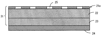
本発明の第1の実施形態について、図1および図3を参照して説明する。図1は、本実施形態の変圧器における低周波吸音構造を形成する低周波吸音部材の構成を示す縦断面図であり、図3は、図1における穴開き部材を音源側から見た正面図である。
[First Embodiment]
A first embodiment of the present invention will be described with reference to FIGS. 1 and 3. FIG. 1 is a longitudinal sectional view showing a configuration of a low-frequency sound absorbing member that forms a low-frequency sound absorbing structure in the transformer of the present embodiment, and FIG. 3 is a front view of the perforated member in FIG. 1 viewed from the sound source side. It is.
以下、図を参照して、本実施形態における低周波吸音部材の構成について説明する。 Hereinafter, the configuration of the low-frequency sound absorbing member in the present embodiment will be described with reference to the drawings.
音源側(図の上側)から順に所定の開口径d1を有する開口部25が所定の間隔pで設けられた穴開き部材である穴開き板21a、グラスウール、ロックウール、アルミニウム繊維材料などの多孔質材またはウレタン、ポリエチレン、アルミニウム発泡材等の連続気泡硬質発泡材からなる吸音材22、および、吸音材22とは吸音特性の異なる繊維状吸音材23が重ね合わせて形成された低周波吸音部材31が、遮音板24の内面に取り付けられている。
Porous material such as
音源側から伝播した音波は、まず、穴開き板21aと穴開き板21a背後の吸音材22、23で形成されたヘルムホルツ型消音器の共鳴効果により、穴開き部材21の開口部25の開口径d1、板厚、背後層および作用範囲で決定される共鳴周波数成分の騒音が低減される。
The sound wave propagated from the sound source side first has an opening diameter of the
さらに、多孔質材または連続気泡硬質発泡材からなる吸音材22と、吸音材22とは吸音特性の異なる繊維状吸音材23とで二重構造とした吸音材自身の吸音効果の組合せ効果により、単体の吸音材で得られる吸音効果と比較して、より広帯域かつ効果的に吸音特性を向上させることができる。
Furthermore, due to the combined effect of the sound absorbing effect of the sound absorbing material itself having a double structure with the
ここで、多孔質材または連続気泡硬質発泡材からなる吸音材22としては、アルミニウム等の金属材料を用いると、吸湿等による性能低下の影響が比較的小さく、環境の変化に対して安定的な効果を得ることができ、また、リサイクルも比較的容易である。
Here, as the
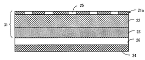
次に、第1の実施形態の変形例について、図2を参照して説明する。図2は、本変形例で用いられる低周波吸音部材の縦断面図である。 Next, a modification of the first embodiment will be described with reference to FIG. FIG. 2 is a longitudinal sectional view of a low-frequency sound absorbing member used in this modification.
図2においては、低周波吸音部材31と遮音板24との間には空気層26が設けられている。本変形例においては、このような構成にすることにより、さらに低周波数領域の吸音特性に優れた吸音構造を実現することができる。
In FIG. 2, an
なお、穴開き板21aの開口部25の数や配置については、図3に示したものに限定されるものではない。また、吸音構造を構成する多孔質材または連続気泡硬質発泡材および繊維状吸音材の厚さについては、穴開き板21aの板厚と開口部25の開口径d1、開口部25の作用範囲および低減の対象となる周波数で決定される寸法の範囲内で、適宜決定すれば良い。
In addition, about the number and arrangement | positioning of the
次に、第1の実施形態のさらに別の変形例について、図4を参照して説明する。 図4は、図3に示した穴開き板21aの変形例を示すものである。本変形例の低周波吸音部材31においては、穴開き板21aは、複数の異なる周波数に対して共鳴するように調整された、複数の異なる開口径d1,d2を有する開口部25を備えたことを特徴としている(図4は、2種類の開口径を有する穴開き部材の場合を示している)。
Next, still another modification of the first embodiment will be described with reference to FIG. FIG. 4 shows a modification of the
このような構成とすることにより、単一の共鳴周波数付近でのみ効果を発揮するヘルムホルツ型の共鳴構造を、異なる複数の周波数に対して効果が発揮できる構成とすることができるので、より広帯域にわたり吸音特性を向上させることが可能となる。 By adopting such a configuration, the Helmholtz-type resonance structure that exhibits an effect only in the vicinity of a single resonance frequency can be configured to exhibit an effect for a plurality of different frequencies. Sound absorption characteristics can be improved.
なお、穴開き板21aの開口部25の配置や個数については、図示したものに限定されるものではない。また、異なる開口径の種類についても、図4では二種類しか示していないが、三種類またはそれ以上の複数の開口径を有する開口部の組合せとしても構わない。
The arrangement and number of the
[第2の実施形態]
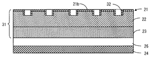
本発明に係る静止誘導電器の第2の実施形態について、第1の実施形態と同様に変圧器を例に挙げ、図5を参照して説明する。図5は、本実施形態に係る変圧器に適用される低周波吸音部材の構成を示す縦断面図であり、図を参照して、本実施形態の低周波吸音部材の構成について説明する。なお、前述した実施形態で参照した図面と同一または類似の部分については、同一の符号を付して説明は省略する。
[Second Embodiment]
A second embodiment of a static induction electric machine according to the present invention will be described with reference to FIG. 5, taking a transformer as an example, as in the first embodiment. FIG. 5 is a longitudinal sectional view showing a configuration of a low-frequency sound absorbing member applied to the transformer according to the present embodiment, and the configuration of the low-frequency sound absorbing member of the present embodiment will be described with reference to the drawings. In addition, the same code | symbol is attached | subjected about the part which is the same as or similar to drawing referred in embodiment mentioned above, and description is abbreviate | omitted.
図において、音源側(図の上側)から順に穴開き部材21、多孔質または連続気泡硬質発泡体の吸音材22、および繊維状吸音材23が重ね合わせて遮音板24に取り付けられている。穴開き部材21は、基板21bに両端開放のパイプ状の開口筒32を貫通させて形成されている。この開口筒32の開口径および長さは、騒音低減の対象となる音波の共鳴周波数によって適宜決定される。
In the figure, a
音源側から伝播した音波は、まず穴開き部材21と穴開き部材21背後の吸音材22、23で構成された部分で形成されたヘルムホルツ型消音器の共鳴効果により、穴開き部材21の開口筒32の開口径、長さ、背後層および作用範囲で決定される共鳴周波数の騒音が低減される。
The sound wave propagated from the sound source side is firstly opened by the resonance effect of the Helmholtz-type silencer formed by the portion constituted by the perforated
さらに、多孔質または連続気泡硬質発泡体からなる吸音材22と繊維状吸音材23とで二重構成とした吸音材自身の吸音効果の組合せ効果により、単体の吸音材で得られる吸音効果と比較して、より広帯域かつ効果的に吸音特性を向上させることができる。
Furthermore, the sound absorption effect of a single sound absorbing material is compared with the combined effect of the sound absorbing effect of the sound absorbing material itself composed of a porous or open-celled rigid foam and the
また、穴開き部材21は基板21bに開口筒32を貫通させて開口部を形成したことで、共鳴に必要な開口部長さに対して、穴開き部材21の基板21bの板厚を薄くすることができるので、吸音性能を確保しつつ、より軽量な吸音構造を実現することができる。
Further, since the opening
また、本構成の変形例として、図6に示すように、吸音材23と遮音板24との間に空気層26を設けてもよい。
As a modification of this configuration, an
以上のような構成により、より低周波数領域の吸音特性に優れ、かつ軽量な吸音構造を実現することができる。 With the configuration as described above, it is possible to achieve a light-absorbing structure that is excellent in sound-absorbing characteristics in a lower frequency region and that is lightweight.
なお、開口筒32の個数や配置については、必ずしも図示したものと一致している必要はなく、対象となる周波数や吸音部材の大きさに合わせて適宜決定すればよい。
Note that the number and arrangement of the opening
次に、第2の実施形態の変形例について、図7を参照して説明する。図7は本変形例の低周波吸音部材の構成を示す縦断面図であり、図において、異なる周波数に共鳴するように調整された、複数の異なる径の開口を有する開口筒32a、32bを基板21bに貫通させて穴開き部材21を形成して、図5に示した例と同様に吸音材22、23と重ね合わせて遮音板24に取り付けたことを特徴としている。
Next, a modification of the second embodiment will be described with reference to FIG. FIG. 7 is a longitudinal sectional view showing the configuration of the low-frequency sound absorbing member of this modification. In the figure, the opening
このような構成とすることにより、単一の共鳴周波数付近でのみ効果を発揮するヘルムホルツ型の共鳴構成を、異なる複数の周波数に対して効果を発揮できる構成とすることができるので、より広帯域の音波に対して吸音特性を向上させることが可能となる。 By adopting such a configuration, the Helmholtz-type resonance configuration that exhibits an effect only in the vicinity of a single resonance frequency can be configured to be effective for a plurality of different frequencies. It is possible to improve sound absorption characteristics with respect to sound waves.
なお、開口筒の配置や個数については、図示したものに限定されるものではない。 Note that the arrangement and number of the opening cylinders are not limited to those illustrated.
また、異なる開口径の開口筒の種類については、図7では大小二種類しか示していないが、三種類またはそれ以上の複数の組合せとしても構わない。 Further, as for the types of the opening cylinders having different opening diameters, only two types of large and small are shown in FIG. 7, but a combination of three or more types may be used.
また、図示していないが、吸音材23と遮音板24の間に図6に示したような空気層を設けても構わない。
Although not shown, an air layer as shown in FIG. 6 may be provided between the
次に、第2の実施形態のさらに別の変形例について、図8を参照して説明する。図8は、本変形例の低周波吸音部材の構成を示す縦断面図であり、異なる周波数に共鳴するように調整された、複数の異なる開口長さが形成された開口筒33a、33bを基板21bに貫通させて穴開き部材21を形成し、吸音材22,23と重ね合わせて低周波吸音部材を形成して遮音板24に取り付けたことを特徴としている。
Next, still another modification of the second embodiment will be described with reference to FIG. FIG. 8 is a longitudinal cross-sectional view showing the configuration of the low-frequency sound absorbing member of the present modification, in which a plurality of opening
このような構成とすることにより、単一の共鳴周波数付近でのみ効果を発揮するヘルムホルツ型の共鳴構成を、異なる複数の周波数において効果を発揮できる構成とすることができるので、より広帯域の音波に対して吸音特性を向上させることが可能となる。 By adopting such a configuration, the Helmholtz-type resonance configuration that exhibits an effect only in the vicinity of a single resonance frequency can be configured to exhibit an effect at a plurality of different frequencies. On the other hand, the sound absorption characteristics can be improved.
なお、開口筒の配置や個数については、図示したものに限定されるものではない。また、異なる開口長さの開口筒の種類についても、図8では長短二種類しか示していないが、三種類またはそれ以上の複数の組合せとしても構わない。 Note that the arrangement and number of the opening cylinders are not limited to those illustrated. Also, regarding the types of opening cylinders having different opening lengths, only two types of long and short are shown in FIG. 8, but a combination of three or more types may be used.
また、開口筒の開口径についても、図8では1種類のみ示されているが、複数の異なる開口径の開口筒の組合せとしても良い。 Further, although only one type of opening diameter of the opening cylinder is shown in FIG. 8, a combination of opening cylinders having a plurality of different opening diameters may be used.
また、図示していないが、吸音材23と遮音板24の間に図6に示す空気層と同様の空気層を設けても構わない。
Although not shown, an air layer similar to the air layer shown in FIG. 6 may be provided between the
[第3の実施形態]
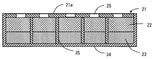
本発明の静止誘導電器の第3の実施形態について、前述した実施形態と同様に、変圧器を例に挙げ、図9を参照して説明する。図9は、本実施形態に係る変圧器における低周波吸音部材の構成を示す縦断面図であり、図を参照して、本実施形態の低周波吸音部材の構成を説明する。なお、前述した実施形態で参照した図面と同一または類似の部分については、同一の符号を付して説明は省略する。
[Third Embodiment]
A third embodiment of the static induction electric machine of the present invention will be described with reference to FIG. 9, taking a transformer as an example, as in the above-described embodiment. FIG. 9 is a longitudinal sectional view showing the configuration of the low-frequency sound absorbing member in the transformer according to this embodiment, and the configuration of the low-frequency sound absorbing member of this embodiment will be described with reference to the drawings. In addition, the same code | symbol is attached | subjected about the part which is the same as or similar to drawing referred in embodiment mentioned above, and description is abbreviate | omitted.
図9において、音源側(図の上側)から順に穴開き板21a、多孔質または連続気泡硬質発泡体からなる吸音材22、および繊維状吸音材23が重ねて設置され、さらに、吸音材22と繊維状吸音材23を覆うように箱状の筐体34が設けられ、パネル状の低周波吸音部材を形成している。また、穴開き板21aには開口部25が形成されている。この開口部25の開口径および開口部25の長さは、対象とする音波の共鳴周波数によって適宜決定されるものである。このパネル状の低周波吸音部材は、同様の構成のもの複数枚を面方向に並べて静止誘導電機の低周波吸音部材とする。
In FIG. 9, a
低周波吸音部材を複数枚のパネル状としたことにより、取扱いが容易になるとともに、可搬性、保管性にも優れた吸音構造とすることが可能となる。 By making the low-frequency sound absorbing member into the shape of a plurality of panels, it becomes easy to handle, and it is possible to provide a sound absorbing structure with excellent portability and storage.
なお、穴開き板21aの開口径、開口長さおよび個数については、必ずしも図示したものに限らない。また、上記実施形態においては、予め吸音対象となる音の周波数と共鳴するように調整された板厚を有する基板に(1)式を満足するよう開口径を有する開口部を形成した穴開き部材を用いたが、基板の板厚を薄くして、(1)式を満足するように内径および長さが調整された円筒状部材を、前記基板を貫通させて形成した穴開き部材に配置するようにしても良い。
The opening diameter, opening length, and number of the
また、図示していないが、吸音材23と筐体34の間に空気層を設けても良い。
Although not shown, an air layer may be provided between the
次に、第3の実施形態の変形例について、図10を参照して説明する。図10は、本変形例の低周波吸音部材の構成を示す縦断面図であり、図において、筐体34内部には開口部25の配置に合わせて仕切り板35が設けられている。
Next, a modification of the third embodiment will be described with reference to FIG. FIG. 10 is a longitudinal sectional view showing the configuration of the low-frequency sound absorbing member of this modification. In the figure, a
このような構成とした場合、仕切り板35の位置を適宜変更することで、穴開き板21aの背後層に相当する容積を容易に変化させることができる。背後層の容積は、前述した式(1)から明らかなように、ヘルムホルツ型消音器の共鳴周波数に対応して形成されている。
In such a configuration, by appropriately changing the position of the
したがって、共鳴周波数を決定する際の構成要因が一つ増えることになり、吸音したい音波の周波数に合わせることが容易になり、より効果的な吸音構造を実現することができる。 Therefore, the constituent factor for determining the resonance frequency increases by one, and it becomes easy to match the frequency of the sound wave to be absorbed, and a more effective sound absorbing structure can be realized.
なお、穴開き板21aの開口部25の開口径、開口部長さおよび個数については、必ずしも図示したものに限らない。また、開口部25については単純な開口の代わりに開口筒としても良い。
The opening diameter, the opening length, and the number of the
また、図示していないが、吸音材23と筐体34の間に空気層を設けても良い。
Although not shown, an air layer may be provided between the
なお、本実施例では、穴開き部材として第1の実施形態に示した開口部が設けられた穴開き板を用いたが、第2の実施形態に示したような基板に開口筒を貫通させて開口部を形成した穴開き部材を用いても良い。 In this example, the perforated plate provided with the opening shown in the first embodiment was used as the perforated member. However, the opening cylinder was passed through the substrate as shown in the second embodiment. Alternatively, a perforated member in which an opening is formed may be used.
[他の実施形態]
以上説明した実施形態は単なる例示であって、本発明はこれらに限定されるものではない。たとえば、異なる種類の実施形態の特徴を種々に組み合わせることもできる。
[Other Embodiments]
The embodiments described above are merely examples, and the present invention is not limited to these. For example, the features of different types of embodiments can be combined in various ways.
1 … 静止誘導電器本体
2 … 防音構造物
3 … 多孔質吸音材
4 … 遮音壁
5 … 低周波吸音部材
6 … 皮膜
7 … 多孔質体層
8 … 金属多孔質吸音板(連続気泡発泡材)
9 … 繊維状吸音材
10 … 空気層
11 … 防音壁
12 … 防音筒
13a… 吸音板
13b… 遮音板
14 … 空洞部
21 … 穴開き部材
21a… 穴開き板
21b… 基板
22 … 多孔質吸音材
23 … 繊維状吸音材
24 … 遮音板
25 … 開口部
26 … 空気層
30 … 共鳴作用範囲
31 … 低周波吸音部材
32、32a、32b、33a、33b … 開口筒
34 … 筐体
35 … 仕切り板
DESCRIPTION OF SYMBOLS 1 ... Static induction electric machine body 2 ... Soundproof structure 3 ... Porous sound absorption material 4 ...
DESCRIPTION OF
Claims (9)
前記特徴周波数の騒音と共鳴するように開口径および開口長が形成された開口部を備えて前記静止誘導電器本体を覆う穴開き部材と、
前記穴開き部材を覆い、多孔質材または連続気泡体のいずれかで構成された連続気泡発泡材と、
前記穴開き部材を覆う繊維状吸音材と、
前記連続気泡発泡材および繊維状吸音材を覆う遮音板と、
を有することを特徴とする、静止誘導電器。 A static induction body that generates noise having a specific characteristic frequency; and
A perforated member that includes an opening having an opening diameter and an opening length so as to resonate with the noise of the characteristic frequency and covers the stationary induction body;
An open-cell foam covering the perforated member and composed of either a porous material or an open-cell body;
A fibrous sound absorbing material covering the perforated member;
A sound insulating plate covering the open cell foam material and the fibrous sound absorbing material;
A static induction machine characterized by comprising:
前記特徴周波数の騒音と共鳴するように開口径および開口長が形成された開口部を備えて前記静止誘導電器本体を覆う穴開き部材と、
前記穴開き部材を覆い、多孔質材または連続気泡体のいずれかで構成された連続気泡発泡材と、
前記穴開き部材を覆う繊維状吸音材と、
前記連続気泡発泡材および繊維状吸音材を覆う遮音板と、
を有することを特徴とする、低周波吸音壁。 A low-frequency sound-absorbing wall covering a stationary induction body that generates noise having a specific characteristic frequency,
A perforated member that includes an opening having an opening diameter and an opening length so as to resonate with the noise of the characteristic frequency and covers the stationary induction body;
An open-cell foam covering the perforated member and composed of either a porous material or an open-cell body;
A fibrous sound absorbing material covering the perforated member;
A sound insulating plate covering the open cell foam material and the fibrous sound absorbing material;
A low-frequency sound-absorbing wall characterized by comprising:
Priority Applications (1)
| Application Number | Priority Date | Filing Date | Title |
|---|---|---|---|
| JP2010275517A JP5872155B2 (en) | 2010-12-10 | 2010-12-10 | Static induction machine and low frequency sound absorbing wall |
Applications Claiming Priority (1)
| Application Number | Priority Date | Filing Date | Title |
|---|---|---|---|
| JP2010275517A JP5872155B2 (en) | 2010-12-10 | 2010-12-10 | Static induction machine and low frequency sound absorbing wall |
Publications (2)
| Publication Number | Publication Date |
|---|---|
| JP2012123293A true JP2012123293A (en) | 2012-06-28 |
| JP5872155B2 JP5872155B2 (en) | 2016-03-01 |
Family
ID=46504775
Family Applications (1)
| Application Number | Title | Priority Date | Filing Date |
|---|---|---|---|
| JP2010275517A Active JP5872155B2 (en) | 2010-12-10 | 2010-12-10 | Static induction machine and low frequency sound absorbing wall |
Country Status (1)
| Country | Link |
|---|---|
| JP (1) | JP5872155B2 (en) |
Cited By (13)
| Publication number | Priority date | Publication date | Assignee | Title |
|---|---|---|---|---|
| CN103779053A (en) * | 2012-10-18 | 2014-05-07 | 株式会社东芝 | Static electric inductor |
| CN105637602A (en) * | 2013-05-21 | 2016-06-01 | 传奇有限公司 | Integrated sound shield for air core reactor |
| CN106504738A (en) * | 2016-10-18 | 2017-03-15 | 国家电网公司 | Ultra-high voltage converter station noise sound absorption device |
| KR101732119B1 (en) * | 2017-01-13 | 2017-05-02 | 주식회사 동인 | Transformer cost |
| KR101753082B1 (en) * | 2017-01-13 | 2017-07-04 | 주식회사 동인 | Transformer noise reduction device |
| CN106968357A (en) * | 2017-04-06 | 2017-07-21 | 上海声望声学科技股份有限公司 | Spatial extent efficient plane sound absorber |
| WO2020251178A1 (en) * | 2019-06-13 | 2020-12-17 | 현대일렉트릭앤에너지시스템(주) | Low-noise transformer |
| WO2021117901A1 (en) * | 2019-12-12 | 2021-06-17 | 旭化成株式会社 | Multilayered sound absorbing material |
| KR20220051572A (en) * | 2020-10-19 | 2022-04-26 | 현대일렉트릭앤에너지시스템(주) | Transformer |
| WO2022186448A1 (en) * | 2021-03-03 | 2022-09-09 | 효성중공업 주식회사 | Noise/vibration reduction device for transformers |
| JP7351429B1 (en) | 2022-12-12 | 2023-09-27 | 株式会社レゾナック | Sound absorbing materials and vehicle parts |
| WO2023189959A1 (en) * | 2022-03-28 | 2023-10-05 | 株式会社レゾナック | Sound-absorbing material and vehicle member |
| CN117211427A (en) * | 2023-11-09 | 2023-12-12 | 迈默智塔(无锡)科技有限公司 | Broad-width silencing device for building and noise reduction plate |
Citations (4)
| Publication number | Priority date | Publication date | Assignee | Title |
|---|---|---|---|---|
| JPH10319970A (en) * | 1997-05-23 | 1998-12-04 | Daiken Trade & Ind Co Ltd | Sound-absorbing and shielding planar material |
| JP2003316364A (en) * | 2002-02-20 | 2003-11-07 | Showa Electric Wire & Cable Co Ltd | Foam and acoustic material using the same, and method for manufacturing the same |
| JP2005338223A (en) * | 2004-05-25 | 2005-12-08 | Showa Electric Wire & Cable Co Ltd | Waterproof sound absorbing material |
| JP2010212350A (en) * | 2009-03-09 | 2010-09-24 | Toshiba Corp | Stationary induction apparatus assembly |
-
2010
- 2010-12-10 JP JP2010275517A patent/JP5872155B2/en active Active
Patent Citations (4)
| Publication number | Priority date | Publication date | Assignee | Title |
|---|---|---|---|---|
| JPH10319970A (en) * | 1997-05-23 | 1998-12-04 | Daiken Trade & Ind Co Ltd | Sound-absorbing and shielding planar material |
| JP2003316364A (en) * | 2002-02-20 | 2003-11-07 | Showa Electric Wire & Cable Co Ltd | Foam and acoustic material using the same, and method for manufacturing the same |
| JP2005338223A (en) * | 2004-05-25 | 2005-12-08 | Showa Electric Wire & Cable Co Ltd | Waterproof sound absorbing material |
| JP2010212350A (en) * | 2009-03-09 | 2010-09-24 | Toshiba Corp | Stationary induction apparatus assembly |
Cited By (18)
| Publication number | Priority date | Publication date | Assignee | Title |
|---|---|---|---|---|
| CN103779053A (en) * | 2012-10-18 | 2014-05-07 | 株式会社东芝 | Static electric inductor |
| CN105637602A (en) * | 2013-05-21 | 2016-06-01 | 传奇有限公司 | Integrated sound shield for air core reactor |
| CN105637602B (en) * | 2013-05-21 | 2018-05-15 | 西门子公司 | Integral type acoustic barrier for air reactor |
| CN106504738A (en) * | 2016-10-18 | 2017-03-15 | 国家电网公司 | Ultra-high voltage converter station noise sound absorption device |
| KR101732119B1 (en) * | 2017-01-13 | 2017-05-02 | 주식회사 동인 | Transformer cost |
| KR101753082B1 (en) * | 2017-01-13 | 2017-07-04 | 주식회사 동인 | Transformer noise reduction device |
| CN106968357A (en) * | 2017-04-06 | 2017-07-21 | 上海声望声学科技股份有限公司 | Spatial extent efficient plane sound absorber |
| KR20200143556A (en) * | 2019-06-13 | 2020-12-24 | 현대일렉트릭앤에너지시스템(주) | Soundproofing Transformer |
| WO2020251178A1 (en) * | 2019-06-13 | 2020-12-17 | 현대일렉트릭앤에너지시스템(주) | Low-noise transformer |
| KR102210362B1 (en) * | 2019-06-13 | 2021-02-03 | 현대일렉트릭앤에너지시스템(주) | Soundproofing Transformer |
| EP3985693A4 (en) * | 2019-06-13 | 2022-11-30 | Hyundai Electric & Energy Systems Co., Ltd. | Low-noise transformer |
| WO2021117901A1 (en) * | 2019-12-12 | 2021-06-17 | 旭化成株式会社 | Multilayered sound absorbing material |
| KR20220051572A (en) * | 2020-10-19 | 2022-04-26 | 현대일렉트릭앤에너지시스템(주) | Transformer |
| KR102449095B1 (en) | 2020-10-19 | 2022-09-29 | 현대일렉트릭앤에너지시스템(주) | Transformer |
| WO2022186448A1 (en) * | 2021-03-03 | 2022-09-09 | 효성중공업 주식회사 | Noise/vibration reduction device for transformers |
| WO2023189959A1 (en) * | 2022-03-28 | 2023-10-05 | 株式会社レゾナック | Sound-absorbing material and vehicle member |
| JP7351429B1 (en) | 2022-12-12 | 2023-09-27 | 株式会社レゾナック | Sound absorbing materials and vehicle parts |
| CN117211427A (en) * | 2023-11-09 | 2023-12-12 | 迈默智塔(无锡)科技有限公司 | Broad-width silencing device for building and noise reduction plate |
Also Published As
| Publication number | Publication date |
|---|---|
| JP5872155B2 (en) | 2016-03-01 |
Similar Documents
| Publication | Publication Date | Title |
|---|---|---|
| JP5872155B2 (en) | Static induction machine and low frequency sound absorbing wall | |
| JP2013021035A (en) | Noise reduction structure for transformer | |
| RU2480561C1 (en) | Acoustic structure of workshop | |
| CN101826323B (en) | Acoustic structure | |
| KR101750957B1 (en) | Acoustic panel and soundproof wall equipment | |
| RU2295089C1 (en) | Sound-proofing guard | |
| JP2008009014A (en) | Porous soundproof structure | |
| CN104700827B (en) | Wideband sound absorbent perforated structure | |
| JPWO2009144818A1 (en) | Speaker system | |
| CN206972377U (en) | The vibration and noise reducing structure and its movable square compartment of generator case | |
| JP2010212350A (en) | Stationary induction apparatus assembly | |
| JP2006276209A (en) | Noise absorption apparatus | |
| JP2019056516A (en) | Noise suppression system | |
| RU2540991C1 (en) | Single-piece sound absorber for acoustic structure of production facility | |
| JP3580810B1 (en) | Sound absorbing device for very low frequency sound | |
| JP2013200426A (en) | Sound absorption structure and electrical equipment with sound absorption structure | |
| CN104246868A (en) | Thin panel for absorbing sound waves emitted by a turbofan of an aircraft nacelle, and nacelle provided with such a panel | |
| JP2013254881A (en) | Electrical apparatus | |
| JP4223438B2 (en) | Porous soundproof structure | |
| CN102737627B (en) | Low-frequency noise-reduction compound template with reverse quadratic residue diffusion structure | |
| CN105575379A (en) | Muffler chamber and muffler used therefor | |
| JP2020057728A (en) | Stationary induction | |
| JPH09306745A (en) | Stationary induction apparatus | |
| RU2665721C1 (en) | Soundproofing enclosure | |
| US20240039364A1 (en) | Covering for a component of an electrical drive system |
Legal Events
| Date | Code | Title | Description |
|---|---|---|---|
| A621 | Written request for application examination |
Free format text: JAPANESE INTERMEDIATE CODE: A621 Effective date: 20131025 |
|
| RD01 | Notification of change of attorney |
Free format text: JAPANESE INTERMEDIATE CODE: A7421 Effective date: 20140110 |
|
| A977 | Report on retrieval |
Free format text: JAPANESE INTERMEDIATE CODE: A971007 Effective date: 20140905 |
|
| A131 | Notification of reasons for refusal |
Free format text: JAPANESE INTERMEDIATE CODE: A131 Effective date: 20140930 |
|
| A02 | Decision of refusal |
Free format text: JAPANESE INTERMEDIATE CODE: A02 Effective date: 20150512 |
|
| A521 | Written amendment |
Free format text: JAPANESE INTERMEDIATE CODE: A523 Effective date: 20150807 |
|
| A911 | Transfer of reconsideration by examiner before appeal (zenchi) |
Free format text: JAPANESE INTERMEDIATE CODE: A911 Effective date: 20150814 |
|
| TRDD | Decision of grant or rejection written | ||
| A01 | Written decision to grant a patent or to grant a registration (utility model) |
Free format text: JAPANESE INTERMEDIATE CODE: A01 Effective date: 20151215 |
|
| A61 | First payment of annual fees (during grant procedure) |
Free format text: JAPANESE INTERMEDIATE CODE: A61 Effective date: 20160113 |
|
| R151 | Written notification of patent or utility model registration |
Ref document number: 5872155 Country of ref document: JP Free format text: JAPANESE INTERMEDIATE CODE: R151 |