JP2012123220A - Lens fixation structure - Google Patents
Lens fixation structure Download PDFInfo
- Publication number
- JP2012123220A JP2012123220A JP2010274247A JP2010274247A JP2012123220A JP 2012123220 A JP2012123220 A JP 2012123220A JP 2010274247 A JP2010274247 A JP 2010274247A JP 2010274247 A JP2010274247 A JP 2010274247A JP 2012123220 A JP2012123220 A JP 2012123220A
- Authority
- JP
- Japan
- Prior art keywords
- lens
- diameter portion
- reference surface
- fixing structure
- frame
- Prior art date
- Legal status (The legal status is an assumption and is not a legal conclusion. Google has not performed a legal analysis and makes no representation as to the accuracy of the status listed.)
- Ceased
Links
Images

Abstract
Description
本発明は、2組(2枚)のレンズを両レンズの間に間隔調整用の間座(スペーサ)を挟んだ状態でレンズ枠に固定するレンズ固定構造に関する。 The present invention relates to a lens fixing structure in which two sets (two) of lenses are fixed to a lens frame in a state where a spacer (spacer) for adjusting a distance is sandwiched between both lenses.
従来、隣接した2組のレンズを、間隔を調整した後、レンズ枠に固定する固定構造として、2枚のレンズの間に間座(シート部材)を挟む構造が知られている(特許文献1)。この特許文献1では、一方のレンズ(第1レンズ)をレンズ枠に挿入してその後面をレンズ枠内の段部に当て付け、次に、間座を挟んで他方のレンズ(第2レンズ)をレンズ枠に挿入し、該レンズ枠の前端雌ねじ部に、第2レンズの前面コバ部に当接する押え環をねじ込んで、間に間座を挟んだ第1、第2レンズを固定していた。この特許文献1では、押え環をねじ部にねじ込む作業があるため作業性が悪い。
Conventionally, a structure in which a spacer (sheet member) is sandwiched between two lenses is known as a fixing structure for fixing two adjacent lenses to a lens frame after adjusting the distance (Patent Document 1). ). In
一方、レンズをレンズ枠に簡単、確実に短時間で固定する方法として、かしめ固定(例えば熱かしめ)する方法がある。特許文献1においても、レンズ枠にねじ込み固定する押え環に代えて、このかしめ固定方法を採用することが可能である。しかし、特許文献1では、第1レンズ、間座及び第2レンズを光軸方向に積層する構造であるので、レンズ間隔を間座の厚さにより調整すると、間座の厚さの違いによってかしめ位置が変化してしまう。このかしめ位置の変化を無視してかしめ固定を行うと、確実なかしめ固定ができない。確実にかしめ固定するためには、間座の厚さが変わるごとにかしめ装置によるかしめ位置を調整しなければならず、かえって時間がかかるという問題があった。
On the other hand, there is a method of caulking and fixing (for example, heat caulking) as a method of easily and surely fixing the lens to the lens frame in a short time. Also in
本発明は、以上の問題意識に基づいてなされたもので、2組のレンズを両レンズの間に間隔調整用の間座(スペーサ)を挟んだ状態でかしめによりレンズ枠に固定するレンズ固定構造において、かしめ位置を変化させることなく、レンズをレンズ枠に固定できるレンズ固定構造を得ることを目的とする。 The present invention has been made on the basis of the above problem awareness, and a lens fixing structure for fixing two sets of lenses to a lens frame by caulking in a state in which a spacer (spacer) for adjusting a distance is sandwiched between both lenses. The purpose of the present invention is to obtain a lens fixing structure capable of fixing the lens to the lens frame without changing the caulking position.
本発明は、筒状のレンズ枠に、間座を挟んだ2組のレンズをレンズ枠の中心軸方向に並ぶように挿入し、該レンズ枠をかしめて固定するレンズ固定構造であって、上記筒状のレンズ枠は、該レンズ枠の中心軸方向の一端部にかしめ部を有し、その内周部分に上記2組のレンズの一方と当接してレンズ枠に対する中心軸方向のレンズ位置を決めるレンズ位置基準面を有すること、上記2組のレンズの一方は、他方のレンズに対向する対向端面と上記レンズ位置基準面に当接する固定基準面を有すること、該一方のレンズは、上記固定基準面をレンズ枠の上記レンズ位置基準面に当接させた状態で、レンズ枠の上記かしめ部をかしめることにより該レンズ枠に固定されていること、及び上記2組のレンズの他方は、上記一方のレンズとの対向端面との間に介在させた間座を介して該一方のレンズに当接して位置決めされ、上記レンズ枠に固定されていること、を特徴としている。 The present invention is a lens fixing structure in which two sets of lenses sandwiching a spacer are inserted in a cylindrical lens frame so as to be aligned in the central axis direction of the lens frame, and the lens frame is caulked and fixed. The cylindrical lens frame has a caulking portion at one end portion in the central axis direction of the lens frame, and abuts one of the two sets of lenses on the inner peripheral portion thereof to position the lens position in the central axis direction with respect to the lens frame. A lens position reference surface to be determined; one of the two sets of lenses has an opposing end surface facing the other lens and a fixed reference surface in contact with the lens position reference surface; the one lens is fixed In the state where the reference surface is in contact with the lens position reference surface of the lens frame, the lens frame is fixed to the lens frame by caulking, and the other of the two sets of lenses is: Opposite end face with one lens It is via a spacer which is interposed between the positioning in contact with one of the lens said, is characterized by, that are fixed to the lens frame.
レンズ枠のレンズ位置基準面は、光軸に直交する同一平面上に形成することが好ましい。 The lens position reference surface of the lens frame is preferably formed on the same plane orthogonal to the optical axis.
レンズ枠には、上記一方のレンズを保持する大径部と中径部を設け、該大径部と中径部の間の段差部に上記レンズ位置基準面を形成するのが実際的である。 It is practical to provide the lens frame with a large-diameter portion and a medium-diameter portion that hold the one lens, and to form the lens position reference surface at a step portion between the large-diameter portion and the medium-diameter portion. .
レンズ枠には、上記他方のレンズを保持する、上記中径部に連続する該中径部よりも小径の小径部を設け、該他方のレンズを、該小径部に挿入して、上記一方のレンズに間座を介して押圧保持するのが好ましい。 The lens frame is provided with a small-diameter portion that is smaller than the medium-diameter portion that is continuous with the medium-diameter portion and holds the other lens, and the other lens is inserted into the small-diameter portion, It is preferable to press and hold the lens via a spacer.
上記間座は、例えば、上記中径部の内径よりも小径で上記小径部の内径よりも大径の中空円板形状のシート部材とし、上記大径部から中径部内に挿入することができる。 The spacer is, for example, a hollow disk-shaped sheet member having a diameter smaller than the inner diameter of the medium diameter portion and larger than the inner diameter of the small diameter portion, and can be inserted into the medium diameter portion from the large diameter portion. .
本発明のレンズ固定構造にあっては、上記2組のレンズの一方の固定基準面と対向端面とは、同一平面上の異なる領域に形成することもできる。 In the lens fixing structure of the present invention, one fixed reference surface and the opposing end surface of the two sets of lenses can be formed in different regions on the same plane.
レンズ枠には、上記一方のレンズを保持する大径部と上記他方のレンズを保持する小径部を設け、該大径部と小径部の間の段差部に上記レンズ位置基準面を形成することが好ましい。 The lens frame is provided with a large-diameter portion that holds the one lens and a small-diameter portion that holds the other lens, and the lens position reference surface is formed at a step portion between the large-diameter portion and the small-diameter portion. Is preferred.
上記小径部は、上記他方のレンズの光軸直交方向の位置調整を可能とする内径を有することが好ましい。 The small-diameter portion preferably has an inner diameter that enables the position adjustment of the other lens in the direction perpendicular to the optical axis.
本発明によれば、筒状のレンズ枠に間座を挟んだ2組のレンズを挿入し、該レンズ枠をかしめて固定するレンズ固定構造において、一方のレンズは、筒状のレンズ枠のレンズ位置基準面とかしめ部との間に挟着保持されるので、間座の厚さを変えてもかしめ位置が変化することがない。そして他方のレンズは、上記かしめ固定したレンズに間座を介して位置決めされるので、容易に、正確に位置決めして固定することができる。 According to the present invention, in a lens fixing structure in which two sets of lenses with a spacer interposed between cylindrical lens frames are inserted and the lens frames are caulked and fixed, one lens is a lens of a cylindrical lens frame. Since it is held between the position reference surface and the caulking portion, the caulking position does not change even if the thickness of the spacer is changed. The other lens is positioned via the spacer on the caulking and fixing lens, so that it can be easily positioned and fixed easily.
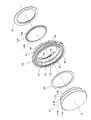
図1、図2は、本発明によるレンズ固定構造の一実施形態を示している。このレンズ固定構造は、撮影レンズの最前(被写体側)の第1レンズ群Lを1群レンズ枠10に保持する実施形態である。1群レンズ枠10は、レンズ鏡筒への搭載時には、他のレンズ枠に結合される。
1 and 2 show an embodiment of a lens fixing structure according to the present invention. This lens fixing structure is an embodiment in which the first lens group L in the forefront (subject side) of the photographing lens is held in the first
第1レンズ群Lは、被写体側から順に位置する第1レンズL1と第2レンズL2の2枚(2組)のレンズからなり、第1レンズL1と第2レンズL2の間に間座(シート部材)20が配置される。前方の第1レンズL1は、後方の第2レンズL2より大径である。 The first lens group L is composed of two (two sets) lenses, a first lens L1 and a second lens L2, which are positioned in order from the subject side, and a spacer (sheet) between the first lens L1 and the second lens L2. Member) 20 is arranged. The front first lens L1 has a larger diameter than the rear second lens L2.
合成樹脂製の1群レンズ枠10は、円筒形の筒状部11を有し、この筒状部11は被写体側の先端部(中心軸方向の先端部、前)から後方に順に、同心の大径部12、中径部13、及び小径部14を備えており、大径部12と中径部13との間の段差部に、中心軸(光軸O)と直交する平面からなるレンズ位置基準面15が形成されている。このレンズ位置基準面15が、第1レンズL1の光軸方向基準位置となる。小径部14は、図1に示すように、周方向に不連続である。大径部12の先端部には、全周に亘って先端部が尖った薄肉のかしめ部(熱かしめ部)16が形成されている。図2には、熱かしめ前のかしめ部16の形状を鎖線で描いた。
The first
第1レンズL1のコバ面(周面)には、前(被写体)側から順に、大径の第1コバ面L1aと小径の第2コバ面L1bが形成されている。第1コバ面L1aと第2コバ面L1bはそれぞれ、大径部12と中径部13に挿入可能な直径に設定された円柱状の外周面形状を呈し、第1コバ面L1aと第2コバ面L1bの間の段差部に、光軸Oと直交する平面形状からなる固定基準面L1cが形成されている。この固定基準面L1cが第1レンズL1の光軸方向基準位置となる。さらに第1レンズL1の後面の有効光学面領域外(コバ部に沿った環状領域)に光軸Oと直交する平面押え面L1dが形成されている。押え面L1dは、第2レンズL2との対向端面である。
A large-diameter first edge surface L1a and a small-diameter second edge surface L1b are formed in order from the front (subject) side on the edge surface (circumferential surface) of the first lens L1. The first edge surface L1a and the second edge surface L1b each have a cylindrical outer peripheral surface shape set to a diameter that can be inserted into the
大径部12は、第1レンズL1の固定基準面L1cをレンズ位置基準面15に当て付けた状態で、かしめ部16のかしめ加工により第1レンズL1をレンズ位置基準面15とで挟圧固定できる長さに形成されている。中径部13の光軸方向の長さは、固定基準面L1cをレンズ位置基準面15に当て付けたときに、押え面L1dと、中径部13と小径部14の間の段差部(光軸直交面)17との間に、間座20を十分な光軸方向の遊びをもって配置できる隙間ができるように形成されている。
The large-
第2レンズL2は、円柱状の外周面形状のコバ面L2aを有し、その前後には、有効光学面領域外に光軸と直交する平面からなる基準面L2bと押え面L2cとが形成されている。基準面L2bは、第1レンズL1との対向端面である。1群レンズ枠10の小径部14の内径は、コバ面L2aの外径よりやや大きく形成され、小径部14の光軸方向の長さは、第2レンズL2のコバ部の厚さ(コバ面L2aの光軸方向の長さ)よりも薄く形成されている。
The second lens L2 has a cylindrical outer peripheral surface L2a, and a reference surface L2b and a pressing surface L2c, which are planes orthogonal to the optical axis, are formed outside the effective optical surface area. ing. The reference surface L2b is an end surface facing the first lens L1. The inner diameter of the
以上の第1レンズL1及び第2レンズL2は、以下のように1群レンズ枠10(筒状部11)に組み付けられる。第1レンズL1と第2レンズL2の間に介在させる間座20の厚さは、例えばロット毎に予め決定されているものとする。まず、1群レンズ枠10の中径部13に、前方から選択した厚さの間座20を挿入する。次に、第1レンズL1を、大径部12に被写体側(前方)から挿入し、固定基準面L1cがレンズ位置基準面15に当て付けられた状態で、筒状部11の先端部のかしめ部16をかしめ加工(熱かしめ)する。このかしめ加工により、かしめ部16は、第1レンズL1の前側のかしめ領域(面取り部)L1e全周に亘って接触し、第1レンズL1をレンズ位置基準面15に押圧する。図2の実線は、熱かしめ後の形状である。
The first lens L1 and the second lens L2 described above are assembled to the first group lens frame 10 (cylindrical portion 11) as follows. It is assumed that the thickness of the
次に筒状部11の後方から小径部14内に、第2レンズL2を第1レンズL1と中心軸(光軸O)方向に並ぶように挿入して間座20を介して第2レンズL2の基準面L2bを第1レンズL1の押え面L1dに当て付ける。この状態で、レンズ押え板21を第2レンズL2に当て付けて筒状部11の後端に取付け、第2レンズL2を間座20を介して第1レンズL1に押圧保持する。この保持状態において、第2レンズL2を、間座20との間及びレンズ押え板21との間の摩擦抵抗等に抗して光軸Oと直交する方向に移動させ、光軸と直交する方向の位置調整を行う。調整終了後に、第2レンズL2とレンズ押え板21の隙間または第2レンズL2と小径部14の隙間に接着剤を注入して、第2レンズL2を筒状部11に固定する。接着剤としては、光硬化型または熱硬化型などが使用できる。
Next, the second lens L2 is inserted into the
以上の実施形態では、レンズ位置基準面15を、内径の異なる大径部12と中径部13の段差部を利用して形成したが、レンズ位置基準面15は、筒状部の内周から内側に突出するフランジ部、突起、凸部等によって形成することも可能である。
In the above embodiment, the lens
また、以上の実施形態では、第1レンズL1には径の異なる第1コバ面L1aと第2コバ面L1bとを形成し、第1コバ面L1aと第2コバ面L1bとの間の段差を利用して光軸Oと直交する固定基準面L1cを形成したが、固定基準面L1cは、第2レンズとの対向端面において間座20と接触しない領域に形成してもよく、その場所は問わない。
In the above embodiment, the first lens L1 has the first edge surface L1a and the second edge surface L1b having different diameters, and the step between the first edge surface L1a and the second edge surface L1b is formed. Although the fixed reference plane L1c orthogonal to the optical axis O is formed by using the fixed reference plane L1c, the fixed reference plane L1c may be formed in a region that does not contact the
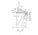
図3は、本発明の第2の実施形態を示すもので、第1レンズL11の固定基準面L11cと対向端面(押え面)L11dを同一平面上の異なる領域に設定している。すなわち、この第2実施形態の第1レンズL11は、そのコバ面(周面)が大径部112に挿入可能な段差のないコバ面(円柱面)L11aとして形成されており、その後面の有効光学面領域外の光軸直交面は、その外側が固定基準面L11cを構成し、内側が押え面L11dを構成している。固定基準面L11cが第1レンズL11の光軸方向基準位置となり、押え面L11dが第2レンズL22との対向端面となる。
FIG. 3 shows a second embodiment of the present invention, in which the fixed reference surface L11c and the opposed end surface (pressing surface) L11d of the first lens L11 are set in different regions on the same plane. That is, in the first lens L11 of the second embodiment, the edge surface (circumferential surface) is formed as an edge surface (cylindrical surface) L11a having no step that can be inserted into the large-
1群レンズ枠110は、円筒形の筒状部111を有し、この筒状部111は同心の大径部112及び小径部114を備えており、大径部112と小径部114との間の段差部に、中心軸(光軸O)と直交する平面からなるレンズ位置基準面115が形成されている。大径部112の先端部には、全周に亘って鎖線で示す先端部が尖った薄肉のかしめ部(熱かしめ部)116が形成されている。
The first
大径部112とかしめ部116は、第1レンズL11の固定基準面L11cをレンズ位置基準面15に当て付けた状態で、かしめ部116のかしめ加工により第1レンズL11をレンズ位置基準面115との間に固定できる長さに形成されている。
The large-
第2レンズL2は、図1、図2に示した第2レンズL2と同一形状であり、円柱状の外周面形状のコバ面L2aを有し、その前後には、有効光学面領域外に光軸と直交する平面からなる基準面L2bと押え面L2cとが形成されている。基準面L2bは、第1レンズL11との対向端面である。 The second lens L2 has the same shape as the second lens L2 shown in FIGS. 1 and 2, and has a cylindrical outer surface L2a. Before and after the second lens L2, light is emitted outside the effective optical surface area. A reference surface L2b and a pressing surface L2c, which are planes orthogonal to the axis, are formed. The reference surface L2b is an end surface facing the first lens L11.
以上の第1レンズL11及び第2レンズL2は、以下のように1群レンズ枠110(筒状部111)に組み付けられる。第1レンズL11と第2レンズL2の間に介在させる間座20の厚さは、例えばロット毎に予め決定されているものとする。第1レンズL11を、大径部112にかしめ部116側(被写体側、前方)から挿入し、固定基準面L11cがレンズ位置基準面115に当て付けられた状態で、かしめ部16をかしめ加工(熱かしめ)する。このかしめ加工により、かしめ部116は、第1レンズL11の前側のかしめ領域((面取り部))L11e全周に亘って接触し、第1レンズL11をレンズ位置基準面115との間に固定する。
The first lens L11 and the second lens L2 described above are assembled to the first group lens frame 110 (cylindrical portion 111) as follows. It is assumed that the thickness of the
次に、1群レンズ枠110の小径部14に、後方から、選択した厚さの間座20を挿入し、その後第2レンズL2を挿入して間座20を介して第2レンズL2の基準面L2bを第1レンズL11の押え面L11dに当て付ける。この状態で、レンズ押え板21を第2レンズL2に当て付けて筒状部111の後端に取付け、第2レンズL2を間座20を介して第1レンズL11に押圧保持する。この状態において、図1、2に示した第1実施形態同様の位置調整を行い、調整終了後に接着剤によって第2レンズL2を筒状部111に固定する。
Next, a
以上の実施形態では2枚(2組)のレンズは、いずれも単レンズであるが、2組のレンズの一方または双方を貼合せレンズとしてもよい。 In the above embodiment, the two lenses (two sets) are both single lenses, but one or both of the two sets of lenses may be a bonded lens.
10 1群レンズ枠(レンズ枠)
11 筒状部
12 大径部
13 中径部
14 小径部
15 レンズ位置基準面
16 かしめ部
17 光軸直交面
20 間座
21 レンズ押え板
111 筒状部
112 大径部
114 小径部
115レンズ位置基準面
116 かしめ部
L 第1レンズ群
L1 第1レンズ
L1a 第1コバ面
L1b 第2コバ面
L1c 固定基準面
L1d 押え面(対向端面)
L1e かしめ領域
L11 第1レンズ
L11a コバ面
L11c 固定基準面
L11d 押え面(対向端面)
L11e かしめ領域
L2 第2レンズ
L2a コバ面
L2b 基準面
L2c 押え面(対向端面)
O 光軸(中心軸)
10 1 group lens frame (lens frame)
DESCRIPTION OF
L1e Caulking region L11 First lens L11a Edge surface L11c Fixed reference surface L11d Pressing surface (opposing end surface)
L11e Caulking region L2 Second lens L2a Edge surface L2b Reference surface L2c Pressing surface (opposing end surface)
O Optical axis (center axis)
Claims (8)
上記筒状のレンズ枠は、該レンズ枠の中心軸方向の一端部にかしめ部を有し、その内周部分に上記2組のレンズの一方と当接してレンズ枠に対する中心軸方向のレンズ位置を決めるレンズ位置基準面を有すること、
上記2組のレンズの一方は、他方のレンズに対向する対向端面と、上記レンズ位置基準面に当接する固定基準面を有すること、
該一方のレンズは、上記固定基準面をレンズ枠の上記レンズ位置基準面に当接させた状態で、レンズ枠の上記かしめ部をかしめることにより該レンズ枠に固定されていること、及び
上記2組のレンズの他方は、上記一方のレンズとの対向端面との間に介在させた間座を介して該一方のレンズに当接して位置決めされ、上記レンズ枠に固定されていること、
を特徴とするレンズ固定構造。 A lens fixing structure in which two sets of lenses sandwiching a spacer are inserted in a cylindrical lens frame so as to be aligned in the central axis direction of the lens frame, and the lens frame is caulked and fixed.
The cylindrical lens frame has a caulking portion at one end in the central axis direction of the lens frame, and a lens position in the central axis direction with respect to the lens frame by contacting one of the two sets of lenses on the inner peripheral portion thereof Having a lens position reference plane to determine
One of the two sets of lenses has a facing end surface that faces the other lens and a fixed reference surface that contacts the lens position reference surface;
The one lens is fixed to the lens frame by caulking the caulking portion of the lens frame in a state where the fixed reference surface is in contact with the lens position reference surface of the lens frame; and The other of the two sets of lenses is positioned in contact with the one lens through a spacer interposed between the lens and the opposite end surface, and is fixed to the lens frame.
Lens fixing structure characterized by
Priority Applications (1)
| Application Number | Priority Date | Filing Date | Title |
|---|---|---|---|
| JP2010274247A JP2012123220A (en) | 2010-12-09 | 2010-12-09 | Lens fixation structure |
Applications Claiming Priority (1)
| Application Number | Priority Date | Filing Date | Title |
|---|---|---|---|
| JP2010274247A JP2012123220A (en) | 2010-12-09 | 2010-12-09 | Lens fixation structure |
Publications (1)
| Publication Number | Publication Date |
|---|---|
| JP2012123220A true JP2012123220A (en) | 2012-06-28 |
Family
ID=46504719
Family Applications (1)
| Application Number | Title | Priority Date | Filing Date |
|---|---|---|---|
| JP2010274247A Ceased JP2012123220A (en) | 2010-12-09 | 2010-12-09 | Lens fixation structure |
Country Status (1)
| Country | Link |
|---|---|
| JP (1) | JP2012123220A (en) |
Cited By (3)
| Publication number | Priority date | Publication date | Assignee | Title |
|---|---|---|---|---|
| US9864159B2 (en) | 2013-07-03 | 2018-01-09 | Denso Corporation | Imaging device having structure using anchor mechanism |
| WO2018049848A1 (en) * | 2016-09-18 | 2018-03-22 | 深圳市光峰光电技术有限公司 | Lens fixing structure, projection equipment and light path system |
| EP4293404A1 (en) | 2022-06-17 | 2023-12-20 | Canon Kabushiki Kaisha | Lens barrel |
Citations (5)
| Publication number | Priority date | Publication date | Assignee | Title |
|---|---|---|---|---|
| JPH0650013U (en) * | 1992-12-15 | 1994-07-08 | 旭光学工業株式会社 | Lens support structure |
| JP2001290063A (en) * | 2000-04-04 | 2001-10-19 | Canon Inc | Lens adhering method and lens holding method |
| JP2008233631A (en) * | 2007-03-22 | 2008-10-02 | Canon Inc | Lens barrel and optical equipment |
| US20090073582A1 (en) * | 2007-09-14 | 2009-03-19 | Hon Hai Precision Industry Co., Ltd. | Lens module |
| JP2010197759A (en) * | 2009-02-26 | 2010-09-09 | Olympus Imaging Corp | Lens assembly |
-
2010
- 2010-12-09 JP JP2010274247A patent/JP2012123220A/en not_active Ceased
Patent Citations (5)
| Publication number | Priority date | Publication date | Assignee | Title |
|---|---|---|---|---|
| JPH0650013U (en) * | 1992-12-15 | 1994-07-08 | 旭光学工業株式会社 | Lens support structure |
| JP2001290063A (en) * | 2000-04-04 | 2001-10-19 | Canon Inc | Lens adhering method and lens holding method |
| JP2008233631A (en) * | 2007-03-22 | 2008-10-02 | Canon Inc | Lens barrel and optical equipment |
| US20090073582A1 (en) * | 2007-09-14 | 2009-03-19 | Hon Hai Precision Industry Co., Ltd. | Lens module |
| JP2010197759A (en) * | 2009-02-26 | 2010-09-09 | Olympus Imaging Corp | Lens assembly |
Cited By (3)
| Publication number | Priority date | Publication date | Assignee | Title |
|---|---|---|---|---|
| US9864159B2 (en) | 2013-07-03 | 2018-01-09 | Denso Corporation | Imaging device having structure using anchor mechanism |
| WO2018049848A1 (en) * | 2016-09-18 | 2018-03-22 | 深圳市光峰光电技术有限公司 | Lens fixing structure, projection equipment and light path system |
| EP4293404A1 (en) | 2022-06-17 | 2023-12-20 | Canon Kabushiki Kaisha | Lens barrel |
Similar Documents
| Publication | Publication Date | Title |
|---|---|---|
| JP6523172B2 (en) | Lens unit and imaging device | |
| JP6393046B2 (en) | Wide-angle lens unit | |
| US8356395B2 (en) | Assembling device for assembling actuator and lens module | |
| JP2012123220A (en) | Lens fixation structure | |
| JP6768678B2 (en) | Camera and how to assemble | |
| WO2009048100A1 (en) | Optical unit and projection display device | |
| JP2011095617A (en) | Lens device | |
| US20110075277A1 (en) | Camera module | |
| JP4790588B2 (en) | Lens barrel and method of adjusting eccentricity of lens barrel | |
| JP2008180762A (en) | Optical axis adjustment device | |
| US8254043B2 (en) | Barrel and lens module with same | |
| WO2019214278A1 (en) | Fixing structure for optical element, lens assembly and illuminance detection device | |
| US8638508B2 (en) | Lens barrel and manufacturing method of the same | |
| JP2019082546A (en) | Image capturing device | |
| KR101032656B1 (en) | Imaging device with variable focus liquid crystal lens | |
| JP2008158260A5 (en) | ||
| US20080273256A1 (en) | Microscope objective and adjusting method therefor | |
| JP2007127445A (en) | Etalon device and method of manufacturing same | |
| JP2012047834A (en) | Lens driving apparatus and camera module | |
| JP2004013103A (en) | Optical parts holder and method for holding optical parts | |
| EP1998198A3 (en) | Optical coupling element and optical coupling unit | |
| JP5317890B2 (en) | Lens barrel | |
| JP2012014113A (en) | LENS FRAME CAPABLE OF fB ADJUSTMENT AND SHIFT ADJUSTMENT, AND ADJUSTER | |
| JPS63136010A (en) | Optical fiber lens assembly | |
| WO2018181887A1 (en) | Imaging device |
Legal Events
| Date | Code | Title | Description |
|---|---|---|---|
| A621 | Written request for application examination |
Free format text: JAPANESE INTERMEDIATE CODE: A621 Effective date: 20131120 |
|
| A977 | Report on retrieval |
Free format text: JAPANESE INTERMEDIATE CODE: A971007 Effective date: 20140820 |
|
| A131 | Notification of reasons for refusal |
Free format text: JAPANESE INTERMEDIATE CODE: A131 Effective date: 20140902 |
|
| AA92 | Notification of invalidation |
Free format text: JAPANESE INTERMEDIATE CODE: A971092 Effective date: 20140916 |