JP2012122603A - Connector device - Google Patents
Connector device Download PDFInfo
- Publication number
- JP2012122603A JP2012122603A JP2011001157A JP2011001157A JP2012122603A JP 2012122603 A JP2012122603 A JP 2012122603A JP 2011001157 A JP2011001157 A JP 2011001157A JP 2011001157 A JP2011001157 A JP 2011001157A JP 2012122603 A JP2012122603 A JP 2012122603A
- Authority
- JP
- Japan
- Prior art keywords
- female
- connector
- male
- pedestal
- casing
- Prior art date
- Legal status (The legal status is an assumption and is not a legal conclusion. Google has not performed a legal analysis and makes no representation as to the accuracy of the status listed.)
- Pending
Links
Images


Classifications
-
- F—MECHANICAL ENGINEERING; LIGHTING; HEATING; WEAPONS; BLASTING
- F16—ENGINEERING ELEMENTS AND UNITS; GENERAL MEASURES FOR PRODUCING AND MAINTAINING EFFECTIVE FUNCTIONING OF MACHINES OR INSTALLATIONS; THERMAL INSULATION IN GENERAL
- F16L—PIPES; JOINTS OR FITTINGS FOR PIPES; SUPPORTS FOR PIPES, CABLES OR PROTECTIVE TUBING; MEANS FOR THERMAL INSULATION IN GENERAL
- F16L37/00—Couplings of the quick-acting type
- F16L37/56—Couplings of the quick-acting type for double-walled or multi-channel pipes or pipe assemblies
-
- F—MECHANICAL ENGINEERING; LIGHTING; HEATING; WEAPONS; BLASTING
- F16—ENGINEERING ELEMENTS AND UNITS; GENERAL MEASURES FOR PRODUCING AND MAINTAINING EFFECTIVE FUNCTIONING OF MACHINES OR INSTALLATIONS; THERMAL INSULATION IN GENERAL
- F16L—PIPES; JOINTS OR FITTINGS FOR PIPES; SUPPORTS FOR PIPES, CABLES OR PROTECTIVE TUBING; MEANS FOR THERMAL INSULATION IN GENERAL
- F16L37/00—Couplings of the quick-acting type
- F16L37/28—Couplings of the quick-acting type with fluid cut-off means
- F16L37/30—Couplings of the quick-acting type with fluid cut-off means with fluid cut-off means in each of two pipe-end fittings
- F16L37/32—Couplings of the quick-acting type with fluid cut-off means with fluid cut-off means in each of two pipe-end fittings at least one of two lift valves being opened automatically when the coupling is applied
- F16L37/34—Couplings of the quick-acting type with fluid cut-off means with fluid cut-off means in each of two pipe-end fittings at least one of two lift valves being opened automatically when the coupling is applied at least one of the lift valves being of the sleeve type, i.e. a sleeve is telescoped over an inner cylindrical wall
Abstract
Description
本発明はコネクタ装置に係り、詳しくは互いに接続可能な雄コネクタおよび雌コネクタが接続対象となる第1装置および第2装置に支持されたコネクタ装置に関する。 The present invention relates to a connector device, and more particularly, to a connector device supported by a first device and a second device to which a male connector and a female connector that can be connected to each other are connected.
液体や気体を導通する管路同士を互いに接続するコネクタ装置として、雌側弁によって開閉される雌側通路を内部に備えた雌コネクタと、雄側弁によって開閉される雄側通路を内部に備えるとともに、前記雌コネクタに出没自在に挿入可能な雄コネクタと有し、前記雌コネクタに前記雄コネクタが挿入されることによって、前記雌側通路および前記雄側通路が接続されるとともに前記雌側弁および前記雄側弁が開かれるようにしたもがある(例えば、特許文献1)。 As a connector device for connecting pipes that conduct liquid or gas to each other, a female connector provided with a female side passage opened and closed by a female side valve and a male side passage opened and closed by a male side valve are provided. And a male connector that can be removably inserted into the female connector, and the female side passage and the male side passage are connected and the female side valve is inserted by inserting the male connector into the female connector. In addition, there is a configuration in which the male valve is opened (for example, Patent Document 1).
互いに連結される第1装置および第2装置に特許文献1のようなコネクタ装置を適用し、各装置の管路同士を接続する場合において、管路同士の接続操作を簡単にするべく、雌コネクタおよび雄コネクタを各装置に支持させ、第1装置および第2装置を連結する際に同時に雌コネクタおよび雄コネクタを接続したいという要求がある。しかしながら、特許文献1のようなコネクタ装置は、雄コネクタおよび雌コネクタを接続するには両者を互いに同軸に配置する必要があるため、第1装置および第2装置への雌コネクタおよび雄コネクタの取り付け位置に誤差がある場合や、第1装置および第2装置の接続位置に誤差が生じた場合に、雌コネクタと雄コネクタとの接続が不能になるという問題がある。
In the case where the connector device as in
本発明は、上記の問題を鑑みてなされたものであって、接続対象となる第1装置および第2装置に支持されるべき雄コネクタおよび雌コネクタを備えたコネクタ装置において、雄コネクタおよび雌コネクタの相対位置にずれが生じる場合にも、両コネクタの接続を可能にすることを課題とする。 The present invention has been made in view of the above problems, and in a connector device including a male connector and a female connector to be supported by a first device and a second device to be connected, a male connector and a female connector It is an object of the present invention to enable the connection of both connectors even when the relative positions of the two are displaced.
上記課題を解決するために、本発明は、雌側弁(25)によって開閉される雌側通路(50)を内部に備えた雌コネクタ(20)と、雄側弁(95)によって開閉される雄側通路(97)を内部に備えるとともに、前記雌コネクタに出没自在に挿入可能な雄コネクタ(90)と有し、前記雌コネクタに前記雄コネクタが挿入されることによって、前記雌側通路および前記雄側通路が接続されるとともに前記雌側弁および前記雄側弁が開かれるコネクタ装置(1)であって、前記雌コネクタを支持するとともに、接続対象の一方となる第1装置(202)に固着されるべき雌側台座(11)と、前記雄コネクタを支持するとともに、接続対象の他方となる第2装置(206)に固着されるべき雄側台座(81)とを有し、前記雌コネクタが前記雌側台座に対して、前記雄コネクタの前記雌コネクタの挿入方向に直交する直交平面に沿って変位可能に支持されている、または前記雄コネクタが前記雄側台座に対して前記直交平面に沿って変位可能に支持されていることを特徴とする。 In order to solve the above problems, the present invention is opened and closed by a female connector (20) having a female passage (50) opened and closed by a female valve (25) and a male valve (95). A male side passage (97) is provided inside and a male connector (90) that can be inserted into and retracted into the female connector, and the male connector is inserted into the female connector, whereby the female side passage and A connector device (1) in which the male side passage is connected and the female side valve and the male side valve are opened, the first device (202) supporting the female connector and being one of the connection targets A female side pedestal (11) to be fixed to the male connector and a male side pedestal (81) to support the male connector and to be fixed to the second device (206) to be connected. Female connector The male connector is supported so as to be displaceable along an orthogonal plane perpendicular to the insertion direction of the female connector of the male connector, or the male connector is along the orthogonal plane with respect to the male side pedestal. It is supported so that it can be displaced.
この構成によれば、雌コネクタおよび雄コネクタの軸線にずれが生じた場合にも、雌コネクタおよび雄コネクタは互いに接続可能な位置へと直交平面に沿って相対変位することができる。また、雌コネクタおよび雄コネクタが各台座に対して複数個設けられる場合に、各コネクタは接続可能な位置に個別に相対変位することができ、他のコネクタの接続による影響を避けることができる。 According to this configuration, even when the female connector and the male connector are displaced from each other, the female connector and the male connector can be relatively displaced along the orthogonal plane to a position where they can be connected to each other. Further, when a plurality of female connectors and male connectors are provided for each pedestal, each connector can be individually displaced relative to a connectable position, thereby avoiding the influence of the connection of other connectors.
本発明のある側面は、前記雌コネクタおよび前記雄コネクタは、少なくとも2対設けられ、前記雌側台座には、前記雄コネクタの前記雌コネクタの挿入方向に直交する直交平面に沿って変位可能に中間台座(501)が支持され、前記中間台座には、前記雌コネクタのそれぞれが、独前記雄コネクタの前記雌コネクタの挿入方向に直交する直交平面に沿って独立して変位可能に支持されていることを特徴とする。なお、雄コネクタが雄側台座に対して変位可能となっている場合には、中間台座を雄側台座に対して変位可能に設け、複数の雄コネクタを中間台座に対して変位可能に設けてもよい。 In one aspect of the present invention, at least two pairs of the female connector and the male connector are provided, and the female pedestal is displaceable along an orthogonal plane orthogonal to the insertion direction of the female connector of the male connector. An intermediate pedestal (501) is supported, and each of the female connectors is supported on the intermediate pedestal so as to be independently displaceable along an orthogonal plane perpendicular to the insertion direction of the female connector of the male connector. It is characterized by being. If the male connector is displaceable with respect to the male pedestal, the intermediate pedestal is provided to be displaceable with respect to the male pedestal, and a plurality of male connectors are provided to be displaceable with respect to the intermediate pedestal. Also good.
この構成によれば、中間台座が複数の雌コネクタ間の相対位置変化を所定の範囲に規制する一方、中間台座が雌側台座に対して変位することによって各雌コネクタを雌側台座に対して大きく変位させることができる。中間台座を雄側台座に設けた場合も同様の効果が得られる。 According to this configuration, the intermediate pedestal regulates the relative position change between the plurality of female connectors within a predetermined range, while the intermediate pedestal is displaced with respect to the female pedestal so that each female connector is relative to the female pedestal. It can be displaced greatly. The same effect can be obtained when the intermediate pedestal is provided on the male pedestal.
本発明のある側面は、前記雄コネクタを前記雌コネクタ内へとガイドするべく、前記雄コネクタを受容する前記雌コネクタの開口端内面(42)がテーパ状に広がっている、または前記雌コネクタに受容される雄コネクタの先端外面がテーパ状に細くなっていることを特徴とする。 In one aspect of the present invention, an inner surface (42) of the open end of the female connector that receives the male connector extends in a tapered shape to guide the male connector into the female connector. The outer surface of the front end of the male connector to be received is tapered.
この構成によれば、雌コネクタと雄コネクタとが挿入方向に対して直交する方向にずれていても、雌コネクタと雄コネクタとのテーパ状部分を介した接触によって、雌コネクタと雄コネクタとが互いに同軸になるように変位する。 According to this configuration, even if the female connector and the male connector are displaced in the direction orthogonal to the insertion direction, the female connector and the male connector are brought into contact with each other through the tapered portion of the female connector and the male connector. Displace to be coaxial with each other.
本発明のある側面は、前記雌コネクタには、前記雌コネクタと前記雄コネクタとの接続部を隠蔽すべく、前記雌側通路と同軸に蛇腹筒状のブーツ(64)が設けられ、前記ブーツの前記雌コネクタ側における端部の内面には、前記雄コネクタを前記雌コネクタ内へとガイドするべく、円錐面状のガイド面(302)が形成されていることを特徴とする。 In one aspect of the present invention, the female connector is provided with a bellows-cylindrical boot (64) coaxially with the female-side passage so as to conceal a connection portion between the female connector and the male connector. A conical guide surface (302) is formed on the inner surface of the end portion on the female connector side in order to guide the male connector into the female connector.
この構成によれば、雌コネクタと雄コネクタとが挿入方向に対して直交する方向にずれていても、ブーツ内面のガイド面が雄コネクタを雄コネクタと同軸となる位置に導く。 According to this configuration, even if the female connector and the male connector are displaced in a direction orthogonal to the insertion direction, the guide surface on the inner surface of the boot guides the male connector to a position coaxial with the male connector.
本発明のある側面は、前記雌側台座および前記雄側台座の一方にはピン受容孔(72)が形成され、前記雌側台座および前記雄側台座の他方には前記ピン受容孔に遊嵌する位置決めピン(126)が突設され、前記雄コネクタと前記雌コネクタとを接続する際において、前記雄コネクタが前記雌コネクタ内に突入するよりも前に前記位置決めピンが前記ピン受容孔内に突入することを特徴とする。 In one aspect of the present invention, a pin receiving hole (72) is formed in one of the female pedestal and the male pedestal, and the other of the female pedestal and the male pedestal is loosely fitted in the pin receiving hole. When the male connector and the female connector are connected, the positioning pin is inserted into the pin receiving hole before the male connector projects into the female connector. It is characterized by rushing.
この構成によれば、位置決めピンがピン受容孔に遊嵌することによって、雌コネクタと雄コネクタとが概ね適切な接続位置、すなわち雌コネクタと雄コネクタとが互いに概ね同軸となる位置に導かれる。 According to this configuration, when the positioning pin is loosely fitted into the pin receiving hole, the female connector and the male connector are guided to a generally appropriate connection position, that is, the position where the female connector and the male connector are substantially coaxial with each other.
本発明のある側面は、前記雄コネクタの前記雌コネクタに突入する側の端部は、円錐面状の凸面(408)に形成され、前記雌コネクタの前記雄コネクタが突入する側の端部は、前記凸面が当接可能な円錐面状の凹面(409)に形成されていることを特徴とする。 In one aspect of the present invention, an end portion of the male connector that protrudes into the female connector is formed as a conical convex surface (408), and an end portion of the female connector into which the male connector enters is The convex surface is formed as a conical concave surface (409) with which the convex surface can abut.
この構成によれば、雄コネクタの円錐状凸面の端部と雌コネクタの円状凹面の端部とが係合することによって、雌コネクタと雄コネクタとが概ね適切な接続位置、すなわち雌コネクタと雄コネクタとが互いに概ね同軸となる位置に導かれる。 According to this configuration, the end of the conical convex surface of the male connector and the end of the circular concave surface of the female connector are engaged with each other, so that the female connector and the male connector are generally in an appropriate connection position, that is, the female connector. The male connector is guided to a position that is substantially coaxial with each other.
以上の構成によれば、接続対象となる第1装置および第2装置に支持されるべき雄コネクタおよび雌コネクタを備えたコネクタ装置において、第1装置および第2装置の相対位置にずれが生じていても、雄コネクタおよび雌コネクタの接続が可能になる。 According to the above configuration, in the connector device including the male connector and the female connector to be supported by the first device and the second device to be connected, the relative positions of the first device and the second device are shifted. However, the male connector and the female connector can be connected.
以下、図面を参照して、本発明を自動車の車体と車載バッテリとを連結する際に、車体に設けられた冷却水循環装置と車載バッテリに形成されたウォータジャケットと連結するコネクタ装置に適用した一実施形態を詳細に説明する。 Hereinafter, with reference to the drawings, the present invention is applied to a connector device that connects a cooling water circulation device provided in a vehicle body and a water jacket formed in the vehicle battery when the vehicle body and the vehicle battery are connected. The embodiment will be described in detail.
(第1実施形態)
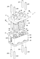
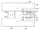
図1および2に示すように、第1実施形態に係るコネクタ装置1は、取り付け対象となる一方の部材に取り付けられる雌側組立体3と、取り付け対象の他方の部材に取り付けられる雄側組立体5とを備えている。雌側組立体3および雄側組立体5は、互いに接離自在となっている。
(First embodiment)
As shown in FIGS. 1 and 2, the
図1〜3および図8に示すように、雌側組立体3は、取り付け対象となる車体202に固着される板状の雌側台座11を備えている。雌側台座11には、上面14から下面15へと貫通する2つの支持孔16が形成されている。支持孔16は、下面15に開口する円孔状の支持孔下部17と、支持孔下部17よりも小径に形成された円孔であり、支持孔下部に連続するとともに上面14に開口する支持孔上部18とを有する段付き孔である。
As shown in FIGS. 1 to 3 and FIG. 8, the female-
各支持孔16には、それぞれ雌コネクタ20が挿通されている。雌コネクタ20は、雌側ケーシング21をなす雌側第1ケーシング22、雌側第2ケーシング23、雌側第3ケーシング24と、雌側ケーシング21内に受容された雌側弁体25と、雌側弁体25と雌側ケーシング21との間に設けられた雌側圧縮コイルばね26とを備えている。
A
雌側第1ケーシング22は、一端に底部31を有する円筒状の基部32を備えている。底部31の中央部には円形状の貫通孔33が形成され、貫通孔33の周縁には基部32から突出する方向にボス部34が形成されている。基部32は、その外径(直径)が支持孔下部17の直径よりも小さく、かつ支持孔上部18の直径よりも大きく形成されているとともに、軸線方向において支持孔下部17の長さよりも短く形成されている。ボス部34の外径(直径)は、支持孔上部18の直径よりも小さく形成されており、ボス部34の外径と支持孔上部18の直径との差は、基部32の外径と支持孔下部17の直径との差よりも大きく設定されている。ボス部34の先端部外周面には、ホースの端部と係合可能なように、周方向に延びる突条状のホース係合部35が形成されている。
The female
雌側第2ケーシング23は、両端が開口した円筒状の大径部36および小径部37が同軸に連続した段付き円筒形状を呈する。大径部36および小径部37の内周面の境界には、段部38が形成されている。大径部36の開口端には外向きのフランジ39が形成されている。フランジ39の外周面は、円周面に形成されており、その円周面には周方向に延在するOリング溝40が形成され、Oリング溝40にはOリング41が嵌め込まれている。フランジ39が基部32内に圧入されることによって、雌側第1ケーシング22と雌側第2ケーシング23とは互いに結合されている。Oリング41は、フランジ39の外周面と基部32の内周面との間を液密にシールする。なお、雌側第1ケーシング22と雌側第2ケーシング23との結合は接着によって行ってもよく、その場合にはOリング41を省略してもよい。
The female
小径部37の開口端内面42は、端部側に向かうほど内径が徐々に大きくなるように円錐面(テーパ面)に形成されている。
The opening end
雌側第3ケーシング24は、円板部46と、円板部46の一方の面の中心部に突設された柱部47とを備えている。円板部46の周縁部は、雌側第2ケーシング23の大径部36の開口端に凹設された溝部43に嵌合し、雌側第2ケーシング23が雌側第1ケーシング22に結合されることによって、雌側第1ケーシング22と雌側第2ケーシング23との間に挟持される。すなわち、雌側第3ケーシング24は、円板部46の周縁部において、雌側第1ケーシング22と雌側第2ケーシング23とに挟持され、雌側第1ケーシング22および雌側第2ケーシング23に結合されている。円板部46が雌側第1ケーシング22および雌側第2ケーシング23に挟持された状態で、柱部47は第2ケーシング内に、大径部36および小径部37と同軸に配置されている。
The female
図3および図4に示すように、柱部47の基端部48および先端部49は、円柱状に形成され、柱部47の他の部分に比べて拡径されている(太くなっている)。柱部47の基端部48には、円板部46の柱部47が設けられた面と相反する面まで貫通する貫通孔51が複数形成されている。この貫通孔51を介して雌側第1ケーシング22のボス部34の内部と雌側第2ケーシング23の大径部36の内部とが連通している。
As shown in FIGS. 3 and 4, the
円板部46が雌側第1ケーシング22および雌側第2ケーシング23に挟持された状態で、柱部47の先端部49は、小径部37の内部に配置されており、小径部37の軸線方向において開口端内面42までは到達していない。先端部49の外周面と小径部37の内周面との間には、環状の空隙が形成されている。先端部49の外周面には周方向に延在するOリング溝52が凹設されており、Oリング溝52にはOリング53が嵌め付けられている。なお、Oリング53は、小径部37の内周面に接触するものではない。先端部49の先端面は、柱部47の軸線に対して直交する平面をなし、その中央部に有底孔である連結孔54が形成されている。以上の雌側第1ケーシング22、雌側第2ケーシング23、雌側第3ケーシング24によって画成される通路を雌側通路50という。
In a state where the
雌側弁体25は、両端が開口した円筒形状をなし、その外径が雌側第2ケーシング23の小径部37の内周面に摺接可能な大きさに形成され、小径部37の内部に受容されている。雌側弁体25の一端には、外向きのフランジ55が突設されており、フランジ55が雌側第2ケーシング23の段部38に引っ掛かることによって、雌側弁体25は小径部37の開口端から抜け出すことがない。雌側弁体25の内周面は、小径部37の開口端側に対応する側に柱部47の先端部49の外周面に摺接可能な小径内壁56と、フランジ55が設けられた側に小径内壁56よりも大径の大径内壁57と、小径内壁56と大径内壁57との境界に段部58を有している。
The
図5Aおよび図5Bに示すように、段部58には、雌側弁体25の軸線方向に延在する溝部59が周方向に所定の間隔をおいて複数形成されている。各溝部59は、雌側弁体25の軸線方向に沿って大径内壁57側に向かうほど深さが徐々に深くなっており、大径内壁57と小径内壁56とを滑らかに連結している。溝部59は、流体が雌側弁体25内を大径内壁57側から小径内壁56側へと流れる際に段部58の障害となる面積を低減するとともに、流体が雌側弁体25内を小径内壁56側から大径内壁57側へと流れる際に段部58において流路が急激に拡大され乱流が生じることを防ぐために設けられている。このように、段部58は、雌側圧縮コイルばね26の受座としての機能を確保しつつ、複数の溝部59によって流体の流れの障害となる面積を低減している。
As shown in FIGS. 5A and 5B, a plurality of
雌側弁体25の外周面には、円周方向に延在するOリング溝61が凹設されており、Oリング溝61にはOリング62が嵌め付けられている。Oリング62は、雌側第2ケーシング23の小径部37の内面と摺接し、雌側弁体25の外面と雌側第2ケーシング23の小径部37の内面との間を液密にシールする。
An O-
雌側弁体25と雌側第3ケーシング24との間には雌側圧縮コイルばね26が介装されている。雌側圧縮コイルばね26は、内部に雌側第3ケーシング24の柱部47を受容し、その一端が雌側第3ケーシング24の円板部46に当接し、他端が雌側弁体25の大径内壁57の内部に突入し、段部58に当接している。雌側弁体25は、雌側圧縮コイルばね26によって雌側第2ケーシング23の小径部37の開口端側へと付勢され、通常時においてはフランジ55が雌側第2ケーシング23の段部38に当接した状態となっている。
A female
通常時、すなわち雌側弁体25のフランジ55が雌側第2ケーシング23の段部38に当接した状態では、雌側弁体25によって雌側第2ケーシング23の小径部37の内周面と雌側第3ケーシング24の先端部49の外周面との間の隙間が閉塞され(雌側通路50が閉塞された雌コネクタ20の閉状態)、雌側弁体25が圧縮コイルばねの付勢力に抗して雌側第2ケーシング23の大径部36側に押し込まれた状態では、雌側第2ケーシング23の小径部37の内周面と雌側第3ケーシング24の先端部49の外周面との間の隙間が開かれる(雌側通路50が開かれた雌コネクタ20の開状態)。
In the normal state, that is, in a state where the
雌側第2ケーシング23の小径部37の外周部には、小径部37の開口端を保護するためのブーツ64が設けられている。また、ブーツ64は、雌コネクタ20と雄コネクタ90とが接続された際に、両コネクタ20、90の接続部を覆い、接続部への異物の侵入を防止する(図7参照)。ブーツ64は、両端が開口した円筒状をなし、一端において小径部37の開口端を受容するとともに、小径部37の外面に形成された凸部に引っ掛けられることによって、小径部37に取り付けられている。ブーツ64の他端は、変形しやすいように蛇腹状に形成され、小径部37の開口端外方へと突出している。
A
雌コネクタ20は、雌側第1ケーシング22のボス部34が支持孔上部18を挿通し、かつ基部32が支持孔下部17内に受容された状態に雌側台座11に配置され、雌側台座11に雌側蓋板67がねじ止めされることによって、雌側台座11に支持される。雌側蓋板67は、雌側第2ケーシング23の大径部36の外径よりも大きく、かつ雌側第1ケーシング22の基部32の外径よりも小さい直径を有する貫通孔68を備えている。貫通孔68の直径と雌側第2ケーシング23の大径部36の外径との差は、基部32の外径と支持孔下部17の直径との差よりも大きく設定されている。雌コネクタ20は、雌側台座11に支持された状態で、ボス部34と支持孔上部18との間、基部32と支持孔下部17との間、雌側第2ケーシング23の大径部36と雌側蓋板67の貫通孔68との間に隙間を有することから、雌コネクタ20は雌側蓋板67に対して、雌コネクタ20の軸線方向と直交する方向、雌コネクタ20の軸線方向と直交する平面に沿って変位可能に支持されている。
The
また、雌側台座11には、下面15に開口する雌ねじ孔71が2つ形成されており、雌ねじ孔71には有底筒体72の底部外面に突設された雄ねじが螺合し、有底筒体72が雌側台座11の下面15に突設されている。有底筒体72は、後述する位置決めピン126を受容する。
The
図1〜図3および図8に示すように、雄側組立体5は、取り付け対象となる車載バッテリ206に固着される板状の雄側台座81を備えている。雄側台座81には、上面84から下面85へと貫通する2つの嵌合孔86が形成されている。嵌合孔86は、上面84に開口する円孔状の嵌合孔上部87と、嵌合孔上部87よりも小径に形成された円孔であり、嵌合孔上部87に連続するとともに下面85に開口する嵌合孔下部88とを有する段付き孔である。
As shown in FIGS. 1 to 3 and 8, the
各嵌合孔86には、それぞれ雄コネクタ90が挿通されている。雄コネクタ90は、雄側ケーシング91をなす雄側第1ケーシング92および雄側第2ケーシング93と、雄側ケーシング91内に受容された雄側弁体95と、雄側弁体95と雄側ケーシング91との間に設けられた雄側圧縮コイルばね96とを備えている。
A
雄側第1ケーシング92は、一端に底部101を有する円筒状の基部102を備えている。底部101の中央部には円形状の貫通孔103が形成され、貫通孔103の周縁には基部102と相反する方向にボス部104が突設されている。基部102の外径(直径)は、嵌合孔上部87にがた付きなく嵌合する大きさに形成されている。ボス部104の外径は嵌合孔下部88を通過可能な大きさに形成されている。ボス部104の先端部外周には、ホースの端部と係合可能なように、周方向に延びる突条状のホース係合部105が形成されている。
The male
雄側第2ケーシング93は、両端が開口した円筒状の筒部106を有している。筒部106の外径は、雌側第2ケーシング23の小径部37の内周面に摺接可能なように設定されており、また雄側第1ケーシング92の基部102の内径よりも小さくなっている。筒部106は、基端面から所定距離離間した位置に周方向に延設された規制壁107を有している。雄側第2ケーシング93は、筒部106の基端が雄側第1ケーシング92の基部102内に挿入され、規制壁107が基部102の端面に当接した状態に雄側第1ケーシング92に組み合わされる。規制壁107の突出端は円周面に形成されており、嵌合孔上部87にがた付きなく嵌合可能となっている。また、筒部106の外周面と基部102の内周面との間にはOリングが介装され、液密にシールされている。なお、雄側第1ケーシング92と雄側第2ケーシング93との結合は接着によって行ってもよく、その場合にはOリングを省略してもよい。以上の雄側第1ケーシング92および雄側第2ケーシング93によって雄側通路97が画成されている。
The male
雄側台座81の上面84には、各嵌合孔86に対応する位置に貫通孔110を有する雄側蓋板109がねじ止めされている。貫通孔110の直径は、雄側第2ケーシング93の筒部106の外径よりも大きく、かつ規制壁107の外径よりも小さく形成されており、雄側蓋板109によって、雄側第1ケーシング92および雄側第2ケーシング93は雄側台座81に支持されている。
On the
雄側第2ケーシング93の筒部106の先端部内周は、他の部分よりも径が狭められた小径内壁111となっており、小径内壁111と他の部分との境界は、円錐面状(テーパ状)の段部112となっている。筒部106の他端側の外周面には、周方向に延在するOリング溝113が形成され、Oリング溝113にはOリング114が嵌め込まれている。
The inner periphery of the distal end of the
筒部106の内部には、雄側弁体95が筒部106の軸線方向に摺動可能に支持されている。雄側弁体95は、大筒部115と、小筒部116と、大筒部115および小筒部116を同軸に連結する4つの連結片117とを有する。隣り合う連結片117の間は開口となっている。大筒部115は、両端が開口した筒状をなし、雄側第2ケーシング93の筒部106の内周面に摺接可能な大きさに形成されている。小筒部116は、一端が雌側第3ケーシング24の連結孔54に嵌合可能な凸部118によって閉塞され、他端が開口している。小筒部116は、雄側第2ケーシング93の筒部106の小径内壁111に摺接可能に形成されている。また、小筒部116の外周面には、周方向に延在するOリング溝119が形成され、Oリング溝119にはOリング120が嵌め込まれている。Oリング120は、小筒部116の外周面と、雄側第2ケーシング93の小径内壁111との間を液密にシールする。
A
連結片117は、大筒部115および小筒部116の軸線回りに90°間隔で配置されており、大筒部115と小筒部116の互いに対応する端面同士を連結している。各連結片117は、雄側第2ケーシング93の段部112に当接する規制面122を外面に有している。雄側弁体95は、小筒部116側が雄側第2ケーシング93の先端側を向くように筒部106内に受容され、各連結片117の規制面122が雄側第2ケーシング93の筒部106の段部112に当接することによって雄側第2ケーシング93の先端部からの抜け止めがなされている。
The connecting
雄側弁体95の大筒部115と雄側第1ケーシング92の底部101との間には、雄側圧縮コイルばね96が介装され、雄側弁体95は雄側圧縮コイルばね96によって雄側第2ケーシング93の先端側へと付勢されている。通常時においては、雄側弁体95は雄側圧縮コイルばね96に付勢され、規制面122が筒部106の段部112に当接するとともに、小筒部116の外周部が筒部106の小径内壁111と対向し、筒部106の開口端が閉塞される(雄側通路97が閉塞された雄コネクタ90の閉状態)。一方、雄側圧縮コイルばね96の付勢力に抗して雄側弁体95が雄側第2ケーシング93の基端側に押し込まれると、小筒部116が小径内壁111から離間し、流体の流通が許容される(雄側通路97が開かれた雄コネクタ90の開状態)。
A male
雄側台座81の上面84の、雌側台座11の2つの雌ねじ孔71に対応する位置には、それぞれ雌ねじ孔125が形成されており、雌ねじ孔125には、位置決めピン126の基端に形成された雄ねじが螺合し、雄側台座81の上面84に2つの位置決めピン126が突設されている。位置決めピン126は、その外径が有底筒体72の内径よりも小さく形成されており、有底筒体72に遊嵌する。位置決めピン126の先端は先細に形成され、有底筒体72の開口端は、その内壁が開口端に向かうほど径が大きくなるようにテーパ状に形成されている。
Female screw holes 125 are formed at positions corresponding to the two female screw holes 71 of the
図1および図2に示すように、雄側台座81の上面84の周縁部には、2つの雄コネクタ90および2つの位置決めピン126を囲むように、周壁89が延設されている。
As shown in FIGS. 1 and 2, a
次に、上述したコネクタ装置1の使用方法および作用、効果について説明する。図1および図8に示すように、雌側組立体3は、雌側台座11がスペーサ201を介して車体202にボルト締結される。車体202は、熱交換器およびポンプを含む冷却水循環装置203を備えており、冷却水循環装置203に接続されたホース204が雌側組立体3のボス部34に接続される。ホース204は、公知のホースバンド等によってボス部34に締結されてよい。
Next, the usage method, operation, and effect of the
雄側組立体5は、雄側台座81がスペーサ205を介して車載バッテリ206にボルト締結される。車載バッテリ206は、ウォータジャケット207を備えており、ウォータジャケット207に接続されたホース208が雄側組立体5のボス部104に接続される。なお、他の実施形態では、ホース208を省略し、ウォータジャケット207または車載バッテリ206に形成された冷却水通路にボス部104が直接に連結されるようにしてもよい。
In the
車体202と車載バッテリ206とは、連結装置209、210を介して互いに連結される。コネクタ装置1は、車体202と車載バッテリ206とが連結装置209、210を介して連結されるに伴って、雌側組立体3と雄側組立体5とにおいて結合し、車体202の冷却水循環装置203と車載バッテリ206のウォータジャケット207と接続し、冷却水の授受を可能にする。
The
車体202と車載バッテリ206とが連結される過程において、車体202と車載バッテリ206とが接近すると、コネクタ装置1は、雌コネクタ20および雄コネクタ90がそれぞれ軸線方向に移動し、最初に雄側組立体5の位置決めピン126の先端が雌側組立体3の有底筒体72の内部に突入する。位置決めピン126の外径が有底筒体72の内径よりも小さく形成されているため、コネクタ装置1の製造誤差や、車体202または車載バッテリ206への取り付け誤差が生じていても、多少の誤差は許容されるようになっている。
In the process in which the
次に、車体202と車載バッテリ206とがより接近すると、雄コネクタ90の雄側第2ケーシング93の先端が雌コネクタ20の雌側第2ケーシング23の開口端に突入する。このとき、雄コネクタ90および雌コネクタ20の軸線が互いにずれでいる場合には、雄側第2ケーシング93の先端周縁部が雌側第2ケーシング23の開口端内面42を押圧する。開口端内面42は円錐面に形成されているため、雄コネクタ90が雌コネクタ20に対して軸線方向に移動すると、雌コネクタ20は径方向に移動し、雄コネクタ90と雌コネクタ20との軸線が一致する。すなわち、開口端内面42はガイド面(カム面)として機能し、雌コネクタ20と雄コネクタ90の調芯を行う。
Next, when the
雄コネクタ90と雌コネクタ20との軸線が一致した後は、雄側第2ケーシング93が雌側第2ケーシング23の小径部37内を進み、雄側第2ケーシング93の先端面が雌側弁体25の端面に当接するとともに、雄側弁体95の凸部118が雌側第3ケーシング24の連結孔54に嵌合する。また、この状態では、雄側第2ケーシング93の外面が雌側第2ケーシング23の小径部37の内面に摺接するとともに、Oリング114が雄側第2ケーシング93の外面と雌側第2ケーシング23の小径部37の内面との間を液密にシールし、雌コネクタ20と雄コネクタ90とが接続された状態となる。
After the axial lines of the
そして、更に雄側第2ケーシング93が雌側第2ケーシング23の小径部37内を進むと、雄側第2ケーシング93が雌側圧縮コイルばね26の付勢力に抗して雌側弁体25を大径部36側に押し込み、雌コネクタ20を開状態へと変化させるとともに、雌側第3ケーシング24が雄側圧縮コイルばね96の付勢力に抗して雄側弁体95を雄側第2ケーシング93の基端側に押し込み、雄コネクタ90を開状態へと変化させ、雌コネクタ20および雄コネクタ90間の流体の流通が可能になる。
When the male
本実施形態に係るコネクタ装置1は、車体202と車載バッテリ206とを連結する際に、雌コネクタ20および雄コネクタ90の軸線が互いにずれていても雌コネクタ20が雌側台座11に対して変位し、雌コネクタ20と雄コネクタ90との軸線を互いに一致させることができる。そのため、雌側組立体3および雄側組立体5の車体202または車載バッテリ206への取り付け誤差が生じていても、雌コネクタ20および雄コネクタ90を確実に接続することができる。すなわち、雌側組立体3および雄側組立体5の車体202または車載バッテリ206への取り付けは高精度であることを必要とせず、取り付け作業性を向上させることができる。また、雌側台座11に対して雌コネクタ20が複数設けられている場合において、ある雌コネクタ20と対応する雄コネクタ90との接続が他の雌コネクタ20と対応する雄コネクタ90との接続を阻害することがない。
In the
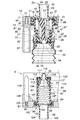
(第2実施形態)
第2実施形態に係るコネクタ装置300は、第1実施形態に係るコネクタ装置1と比較して、雌側第2ケーシング23と、ブーツ64との形状のみが異なる。コネクタ装置300の他の構成は、コネクタ装置1と同様の構成であるため、コネクタ装置1と同様の符号を付して説明を省略する。
(Second Embodiment)
The
図9に示すように、コネクタ装置300の雌側第2ケーシング23は、小径部37の開口端内面42が円錐面に形成されておらず、直管状となっている。
As shown in FIG. 9, the female-side
コネクタ装置300のブーツ64は、両端が開口した円筒状をなし、基端において小径部37の開口端を受容するとともに、小径部37の外面に形成された凸部に引っ掛けられることによって、小径部37に取り付けられている。ブーツ64は、小径部37の開口端に対応する部分において縮径され、その内面は小径部37の開口端面上へと張り出した張出部301を形成している。張出部301のブーツ64の先端側には、先端側に進むにつれて徐々に拡径する円錐面状のガイド面302を内面に備えたガイド部303が形成されている。ガイド部303のブーツ64の先端側には、ブーツ64の軸線方向に伸縮可能な蛇腹部304となっている。ガイド部303は、蛇腹部304に比べて肉厚が厚く形成されており、変形し難くなっている。
The
第2実施形態では、第1実施形態での小径部37の開口端内面42に代わり、ブーツ64のガイド面302が雌コネクタ20と雄コネクタ90の調芯を行う。すなわち、雄コネクタ90と雌コネクタ20と接続する際には、雄側第2ケーシング93の先端周縁部がブーツ64のガイド面302上を摺動し、雌コネクタ20を径方向に移動させ、両コネクタ20、90の軸線を同軸にする。
In the second embodiment, the
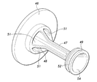
(第3実施形態)
第3実施形態に係るコネクタ装置400は、第1実施形態に係るコネクタ装置1と比較して、雌側弁体25、雌側第3ケーシング24、雄側第2ケーシング93および雄側弁体95の形状が異なり、ブーツ61、有底筒体72および位置決めピン126が省略されている。コネクタ装置400の他の構成は、コネクタ装置1と同様の構成であるため、コネクタ装置1と同様の符号を付して説明を省略する。
(Third embodiment)
Compared with the
図10に示すように、コネクタ装置400における雌側第3ケーシング24の先端部49の先端面には、柱部47の軸線を中心とした円錐面状の凹部である連結孔401が形成されている。雌側弁体25の小径部37の開口端側に対応する側は、雌側第3ケーシング24の先端部49よりも小径部37の開口端側に突出する延長部402を備えている。延長部402には、連結孔401と協働して1つの連続した凹状の円錐面を形成するようにテーパ面403が形成されている。
As shown in FIG. 10, a connecting
コネクタ装置400における雄側弁体95の小筒部116は、一端が雌側第3ケーシング24の連結孔401に嵌合可能な円錐状の凸部405によって閉塞されている。凸部405は、雄側第2ケーシング93の筒部106の先端部から突出しており、筒部106の先端部は凸部405と協働して1つの連続した凸状の円錐面を形成するようにテーパ面406が形成されている。凸部405とテーパ面406とによって形成される連続した円錐状の凸部408は、連結孔401とテーパ面403とによって形成される連続した円錐状の凹部409に嵌合可能となっている。
One end of the
このように、コネクタ装置400では、雄コネクタ90の先端に、凸部405とテーパ面406とから形成される比較的大きな円錐状の凸部408を設けたため、雄コネクタ90自身が位置決めピンとして機能し、凸部405で雌側第2ケーシング23の開口端内面42と摺接して、雌コネクタ20と雄コネクタ90との調芯を行うことができる。この構成により、位置決めピン126および有底筒体72は省略可能となる。
As described above, in the
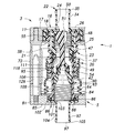
(第4実施形態)
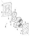
第4実施形態に係るコネクタ装置500は、第1実施形態に係るコネクタ装置1と比較して、雌側台座11に対する雌コネクタ20の支持構造が異なり、雌コネクタ20は中間台座501を介して雌側台座11に支持されている。コネクタ装置500の他の構成は、コネクタ装置1と同様の構成であるため、コネクタ装置1と同様の符号を付して説明を省略する。
(Fourth embodiment)
The
図11および図12に示すように、中間台座501は、2つの雌コネクタ20を独立して変位可能に支持するものである。中間台座501の下面には、雌コネクタ20の雌側第1ケーシング22の基部32が遊嵌可能な有底の中間台座孔502が2つ形成されている。中間台座孔502は、基部32の直径よりも大きく形成されており、基部32は中間台座孔502内で雌コネクタ20の軸線に直交する方向に変位可能となっている。また、各中間台座孔502の底部には、中間台座501の上面側へと貫通し、雌側第1ケーシング22のボス部34が挿通される貫通孔503が形成されている。貫通孔503の直径は、雌コネクタ20が中間台座孔502内で変位しても雌側第1ケーシング22のボス部34が貫通孔503に当接しないように、雌側第1ケーシング22のボス部34の外径よりも十分に大きく形成されている。
As shown in FIGS. 11 and 12, the
雌側台座11の下面には、中間台座501が遊嵌可能な有底の中間台座支持孔505が形成されている。中間台座支持孔505の底部であって、受容された中間台座501の2つの貫通孔503に対応する部分には、雌側台座11の上面側へと貫通し、中間台座501に支持された雌コネクタ20の雌側第1ケーシング22のボス部34が挿通される、2つの貫通孔506が形成されている。雌側台座11の貫通孔506は、中間台座501内で雌コネクタ20が変位し、かつ中間台座501が中間台座支持孔505内で変位してもボス部34が貫通孔506に当接しないように、直径が十分に大きく設定されている。
A bottomed intermediate
2つの雌コネクタ20が中間台座501の2つの中間台座孔502に変位可能に受容され、中間台座501が雌側台座11の中間台座支持孔505に変位可能に受容された状態で、雌側台座11の下面には雌側蓋板67がねじにより締結される。雌側蓋板67には、雌側第2ケーシング23の大径部36の外径よりも大きく、かつ雌側第1ケーシング22の基部32の外径よりも小さい直径を有する貫通孔68が形成されている。この雌側蓋板67によって、2つの雌コネクタ20が中間台座501の2つの中間台座孔502に変位可能に受容され、中間台座501が雌側台座11の中間台座支持孔505に変位可能に受容された状態が維持される。
The two
コネクタ装置500では、中間台座501を介して各雌コネクタ20を雌側台座11に支持するようにしたため、各雌コネクタ20間の相対変位を所定の範囲に規制しつつ、中間台座501を雌側台座11に対して変位させることによって、両雌コネクタ20を同時に大きな範囲で変位させることが可能になる。すなわち、コネクタ装置500は、両雌コネクタ20を雌側台座11に対して大きな範囲で変位可能としたいが、両雌コネクタ20間の相対変位は小さな範囲で行いたいという場合に有効である。
In the
以上の第4実施形態に係るコネクタ装置500は、中間台座501に雌コネクタ20を2つ支持させる構成としたが、中間台座501に雌コネクタ20を3つ以上支持させることも可能である。また、雄コネクタ90側に適用し、複数の雄コネクタ90を中間台座を介して雄側台座81に支持させるようにしてもよい。
Although the
以上で具体的実施形態の説明を終えるが、本発明は上記実施形態に限定されることなく幅広く変形実施することができる。例えば、本実施形態では雌コネクタ20を雌側台座11に対して変位可能に支持したが、雄コネクタ90を雄側台座81に対して変位可能に支持してもよい。この場合には、嵌合孔上部87の直径を雄側第1ケーシング92の基部102の外径および規制壁107の外径よりも大きくすればよい。また、実施形態では、雌側第2ケーシング23の開口端内面42を円錐面に形成したが、この構成に代えて、或いはこの構成に加えて、雄側第2ケーシング93の筒部106の先端部外周面を先細となる円錐面に形成してもよい。また、位置決めピン126および有底筒体72は、他の実施形態においては省略してもよい。実施形態では、雌側台座11および雄側台座81を、車体202または車載バッテリ206の表面に筒状のスペーサ201、205を介してボルト締結したが、他の実施形態では、雌側台座11および雄側台座81を車体202または車載バッテリ206の表面に溶接や接着剤等によって直接に固着してもよいし、車体202または車載バッテリ206に一体に形成してもよい。また、実施形態では、車体202および車載バッテリ206の冷却水通路を接続する例を示したが、取り付け対象となる装置には種々の装置を適用することができる。
Although the description of the specific embodiment is finished as described above, the present invention is not limited to the above embodiment and can be widely modified. For example, in this embodiment, the
1、300、400、500…コネクタ装置、3…雌側組立体、5…雄側組立体、11…雌側台座、16…支持孔、20…雌コネクタ、21…雌側ケーシング、25…雌側弁体、42…開口端内面、50…雌側通路、64…ブーツ、72…有底筒体、81…雄側台座、90…雄コネクタ、91…雄側ケーシング、95…雄側弁体、97…雄側通路、126…位置決めピン、202…車体、206…車載バッテリ、302…ガイド面、408…凸部、409…凹部、501…中間台座、502…中間台座孔、505…中間台座支持孔
DESCRIPTION OF SYMBOLS 1,300,400,500 ... Connector apparatus, 3 ... Female side assembly, 5 ... Male side assembly, 11 ... Female side base, 16 ... Support hole, 20 ... Female connector, 21 ... Female side casing, 25 ... Female Side valve body, 42 ... Open end inner surface, 50 ... Female side passage, 64 ... Boot, 72 ... Bottomed cylindrical body, 81 ... Male side pedestal, 90 ... Male connector, 91 ... Male side casing, 95 ... Male
本発明のある側面は、前記雌コネクタおよび前記雄コネクタは、少なくとも2対設けられ、前記雌側台座には、前記雄コネクタの前記雌コネクタの挿入方向に直交する直交平面に沿って変位可能に中間台座(501)が支持され、前記中間台座には、前記雌コネクタのそれぞれが、前記雄コネクタの前記雌コネクタの挿入方向に直交する直交平面に沿って独立して変位可能に支持されていることを特徴とする。なお、雄コネクタが雄側台座に対して変位可能となっている場合には、中間台座を雄側台座に対して変位可能に設け、複数の雄コネクタを中間台座に対して変位可能に設けてもよい。
In one aspect of the present invention, at least two pairs of the female connector and the male connector are provided, and the female pedestal is displaceable along an orthogonal plane orthogonal to the insertion direction of the female connector of the male connector. intermediate base (501) is supported, wherein the intermediate base, wherein each of the female connector, is independently displaceably supported along the orthogonal plane orthogonal to the insertion direction of the female connector before Kieu connector It is characterized by being. If the male connector is displaceable with respect to the male pedestal, the intermediate pedestal is provided to be displaceable with respect to the male pedestal, and a plurality of male connectors are provided to be displaceable with respect to the intermediate pedestal. Also good.
Claims (7)
前記雌コネクタを支持するとともに、接続対象の一方となる第1装置に固着されるべき雌側台座と、
前記雄コネクタを支持するとともに、接続対象の他方となる第2装置に固着されるべき雄側台座とを有し、
前記雌コネクタが前記雌側台座に対して、前記雄コネクタの前記雌コネクタの挿入方向に直交する直交平面に沿って変位可能に支持されている、または前記雄コネクタが前記雄側台座に対して前記直交平面に沿って変位可能に支持されていることを特徴とするコネクタ装置。 A female connector having a female-side passage opened and closed by a female-side valve; a male connector having a male-side passage opened and closed by a male-side valve; A connector device in which the female side passage and the male side passage are connected and the female side valve and the male side valve are opened by inserting the male connector into the female connector,
A female pedestal that supports the female connector and is to be fixed to the first device to be connected;
A male pedestal to support the male connector and to be fixed to the second device to be connected;
The female connector is supported so as to be displaceable along an orthogonal plane perpendicular to the insertion direction of the female connector of the male connector with respect to the female side pedestal, or the male connector is supported with respect to the male side pedestal The connector device is supported so as to be displaceable along the orthogonal plane.
前記雌側台座には、前記雄コネクタの前記雌コネクタの挿入方向に直交する直交平面に沿って変位可能に中間台座が支持され、
前記中間台座には、前記雌コネクタのそれぞれが、独前記雄コネクタの前記雌コネクタの挿入方向に直交する直交平面に沿って独立して変位可能に支持されていることを特徴とする請求項1に記載のコネクタ装置。 The female connector and the male connector are provided in at least two pairs,
An intermediate pedestal is supported on the female pedestal so that it can be displaced along an orthogonal plane perpendicular to the insertion direction of the female connector of the male connector,
2. Each of the female connectors is supported on the intermediate base so as to be independently displaceable along an orthogonal plane orthogonal to the insertion direction of the female connector of the male connector. The connector device according to 1.
前記雄側台座には、前記雄コネクタの前記雌コネクタの挿入方向に直交する直交平面に沿って変位可能に中間台座が支持され、
前記中間台座には、前記雄コネクタのそれぞれが、独前記雄コネクタの前記雌コネクタの挿入方向に直交する直交平面に沿って独立して変位可能に支持されていることを特徴とする請求項1に記載のコネクタ装置。 The female connector and the male connector are provided in at least two pairs,
An intermediate pedestal is supported on the male pedestal so as to be displaceable along an orthogonal plane orthogonal to the insertion direction of the female connector of the male connector,
2. The intermediate pedestal, wherein each of the male connectors is supported so as to be independently displaceable along an orthogonal plane orthogonal to the insertion direction of the female connector of the male connector. The connector device according to 1.
前記ブーツの前記雌コネクタ側における端部の内面には、前記雄コネクタを前記雌コネクタ内へとガイドするべく、円錐面状のガイド面が形成されていることを特徴とする請求項1〜請求項3のいずれか1つの項に記載のコネクタ装置。 The female connector is provided with a bellows cylindrical boot coaxially with the female side passage so as to conceal the connection between the female connector and the male connector,
A conical guide surface is formed on an inner surface of an end of the boot on the female connector side so as to guide the male connector into the female connector. Item 4. The connector device according to any one of Items 3.
前記雌側台座および前記雄側台座の他方には前記ピン受容孔に遊嵌する位置決めピンが突設され、
前記雄コネクタと前記雌コネクタとを接続する際において、前記雄コネクタが前記雌コネクタ内に突入するよりも前に前記位置決めピンが前記ピン受容孔内に突入することを特徴とする請求項1〜請求項5のいずれか1つの項に記載のコネクタ装置。 A pin receiving hole is formed in one of the female side pedestal and the male side pedestal,
On the other side of the female side pedestal and the male side pedestal, a positioning pin loosely fitted in the pin receiving hole is projected,
2. When the male connector and the female connector are connected, the positioning pin enters the pin receiving hole before the male connector enters the female connector. The connector apparatus as described in any one of Claim 5.
前記雌コネクタの前記雄コネクタが突入する側の端部は、前記凸面が当接可能な円錐面状の凹面に形成されていることを特徴とする請求項1〜請求項3のいずれか1つの項に記載のコネクタ装置。 The end of the male connector on the side that enters the female connector is formed as a conical convex surface,
The end of the female connector on the side into which the male connector enters is formed as a conical concave surface with which the convex surface can abut. The connector device according to item.
Priority Applications (2)
| Application Number | Priority Date | Filing Date | Title |
|---|---|---|---|
| JP2011001157A JP2012122603A (en) | 2010-11-15 | 2011-01-06 | Connector device |
| PCT/JP2011/005839 WO2012066728A1 (en) | 2010-11-15 | 2011-10-19 | Connector device |
Applications Claiming Priority (3)
| Application Number | Priority Date | Filing Date | Title |
|---|---|---|---|
| JP2010254395 | 2010-11-15 | ||
| JP2010254395 | 2010-11-15 | ||
| JP2011001157A JP2012122603A (en) | 2010-11-15 | 2011-01-06 | Connector device |
Publications (1)
| Publication Number | Publication Date |
|---|---|
| JP2012122603A true JP2012122603A (en) | 2012-06-28 |
Family
ID=46083681
Family Applications (1)
| Application Number | Title | Priority Date | Filing Date |
|---|---|---|---|
| JP2011001157A Pending JP2012122603A (en) | 2010-11-15 | 2011-01-06 | Connector device |
Country Status (2)
| Country | Link |
|---|---|
| JP (1) | JP2012122603A (en) |
| WO (1) | WO2012066728A1 (en) |
Cited By (4)
| Publication number | Priority date | Publication date | Assignee | Title |
|---|---|---|---|---|
| JP2014025555A (en) * | 2012-07-27 | 2014-02-06 | Nifco Inc | Pipe joint component and pipe joint |
| JP2014025556A (en) * | 2012-07-27 | 2014-02-06 | Nifco Inc | Pipe joint composing member |
| WO2015046207A1 (en) | 2013-09-24 | 2015-04-02 | Meiji Seikaファルマ株式会社 | Production method for diazabicyclooctane derivative and intermediary body thereof |
| WO2015053297A1 (en) | 2013-10-08 | 2015-04-16 | Meiji Seikaファルマ株式会社 | Crystals of diazabicyclooctane derivative and production method for crystals of diazabicyclooctane derivative |
Families Citing this family (2)
| Publication number | Priority date | Publication date | Assignee | Title |
|---|---|---|---|---|
| DE102017128022A1 (en) | 2017-11-27 | 2019-05-29 | Airbus Operations Gmbh | Coupling system for providing a plurality of fluid connections |
| EP3792535A1 (en) * | 2019-09-12 | 2021-03-17 | A. Raymond et Cie | Flow control valve and system for cleaning a vehicle surface |
Family Cites Families (4)
| Publication number | Priority date | Publication date | Assignee | Title |
|---|---|---|---|---|
| JPS5111218A (en) * | 1974-07-18 | 1976-01-29 | Yokohama Aeroquip | OOTOKATSU PURINGUSOCHI |
| JPS59151687A (en) * | 1983-02-15 | 1984-08-30 | 三菱重工業株式会社 | Automatic detachable device for piping |
| JPH0317116Y2 (en) * | 1988-03-30 | 1991-04-11 | ||
| ITMI20051643A1 (en) * | 2005-09-07 | 2007-03-08 | Faster Spa | QUICK COUPLING WITH COMPENSATION OF THE COUPLING TOLERANCES |
-
2011
- 2011-01-06 JP JP2011001157A patent/JP2012122603A/en active Pending
- 2011-10-19 WO PCT/JP2011/005839 patent/WO2012066728A1/en active Application Filing
Cited By (11)
| Publication number | Priority date | Publication date | Assignee | Title |
|---|---|---|---|---|
| JP2014025555A (en) * | 2012-07-27 | 2014-02-06 | Nifco Inc | Pipe joint component and pipe joint |
| JP2014025556A (en) * | 2012-07-27 | 2014-02-06 | Nifco Inc | Pipe joint composing member |
| WO2015046207A1 (en) | 2013-09-24 | 2015-04-02 | Meiji Seikaファルマ株式会社 | Production method for diazabicyclooctane derivative and intermediary body thereof |
| KR20160058851A (en) | 2013-09-24 | 2016-05-25 | 메이지 세이카 파루마 가부시키가이샤 | Production method for diazabicyclooctane derivative and intermediary body thereof |
| WO2015053297A1 (en) | 2013-10-08 | 2015-04-16 | Meiji Seikaファルマ株式会社 | Crystals of diazabicyclooctane derivative and production method for crystals of diazabicyclooctane derivative |
| KR20160065871A (en) | 2013-10-08 | 2016-06-09 | 메이지 세이카 파루마 가부시키가이샤 | Crystals of diazabicyclooctane derivative and production method for crystals of diazabicyclooctane derivative |
| EP3299370A1 (en) | 2013-10-08 | 2018-03-28 | Meiji Seika Pharma Co., Ltd. | Crystalline forms of diazabicyclooctane derivative and production process thereof |
| RU2695219C2 (en) * | 2013-10-08 | 2019-07-22 | Мейдзи Сейка Фарма Ко., Лтд. | Crystalline forms of diazabicyclooctane derivative and method for production thereof |
| EP3613740A1 (en) | 2013-10-08 | 2020-02-26 | Meiji Seika Pharma Co., Ltd. | Preparation of a diazabicyclooctane derivative |
| EP3613741A1 (en) | 2013-10-08 | 2020-02-26 | Meiji Seika Pharma Co., Ltd. | Preparation of a diazabicyclooctane derivative |
| KR20220054694A (en) | 2013-10-08 | 2022-05-03 | 메이지 세이카 파루마 가부시키가이샤 | Crystals of diazabicyclooctane derivative and production method for crystals of diazabicyclooctane derivative |
Also Published As
| Publication number | Publication date |
|---|---|
| WO2012066728A1 (en) | 2012-05-24 |
Similar Documents
| Publication | Publication Date | Title |
|---|---|---|
| WO2012066728A1 (en) | Connector device | |
| JP6388764B2 (en) | Quick connector joint | |
| US7731245B2 (en) | Quick connector coupling | |
| JP6506500B2 (en) | Quick coupler | |
| US7677608B2 (en) | Quick connector | |
| JP4986520B2 (en) | Coupling device for fluid transfer | |
| TW201137266A (en) | Fluid coupling | |
| RU2718840C2 (en) | Plug connector for connection of pipelines for liquid or gaseous media | |
| US11598463B2 (en) | Quick connector with verification | |
| JP4653688B2 (en) | Pipe fitting | |
| KR101878041B1 (en) | Pipe connecting apparatus capable of removing residual pressure and air conditioner | |
| EP4008946B1 (en) | A connector having a guided pilot | |
| EP3140583B1 (en) | Compression fitting with coupled ferrule | |
| US20220299142A1 (en) | Coupling and method for assembling the same | |
| EP3862609A1 (en) | Fluid coupling system | |
| JP2017082863A (en) | Female joint member and pipe joint including female joint member | |
| CN111247365A (en) | Pipeline connects device soon | |
| JP3185066U (en) | Branch joint | |
| JP5951395B2 (en) | Pipe fitting components | |
| CN219345621U (en) | Main valve device and switching valve with same | |
| EP3677819B1 (en) | Check valve assembly | |
| CN111742171B (en) | Connector for loop element | |
| WO2023166148A1 (en) | System and method for centralizing a quick connect nipple | |
| WO2021165715A1 (en) | Quick connector | |
| JP2013024278A (en) | Coupler for heat pipe |