JP2012120812A - Dental support system using video camera for dental treatment - Google Patents
Dental support system using video camera for dental treatment Download PDFInfo
- Publication number
- JP2012120812A JP2012120812A JP2010285109A JP2010285109A JP2012120812A JP 2012120812 A JP2012120812 A JP 2012120812A JP 2010285109 A JP2010285109 A JP 2010285109A JP 2010285109 A JP2010285109 A JP 2010285109A JP 2012120812 A JP2012120812 A JP 2012120812A
- Authority
- JP
- Japan
- Prior art keywords
- affected area
- image
- optical axis
- video camera
- video
- Prior art date
- Legal status (The legal status is an assumption and is not a legal conclusion. Google has not performed a legal analysis and makes no representation as to the accuracy of the status listed.)
- Pending
Links
Images


Abstract
Description
本発明は、歯科治療における治療対象患部の映像をビデオカメラで撮影し、モニターディスプレイ上に表示する手術等の医療支援カメラシステムおよび表示方法に関する。 The present invention relates to a medical support camera system and a display method for surgery or the like in which an image of an affected area to be treated in dental treatment is taken with a video camera and displayed on a monitor display.
医療治療の現場においては治療対象患部をビデオカメラで撮像し、その映像をモニターのディスプレイ上に表示、視覚認識することで医療治療を支援する装置を用いている。ビデオカメラによる患部の視覚認識は該患部をズームアウト(縮小)したり、ズームイン(拡大)したりして該患部映像をモニターディスプレイ上に表示し、医療処置や患部状態把握などに利用されている。また該患部映像認識には陰影の少ない照明が必要であり、手術には無影灯が用いられている。 In the field of medical treatment, an apparatus for supporting medical treatment is used by imaging a diseased part to be treated with a video camera, displaying the image on a monitor display, and visually recognizing the image. Visual recognition of an affected area by a video camera is used for medical treatment or grasping the condition of the affected area by zooming out (reducing) or zooming in (enlarging) the affected area and displaying the affected area image on a monitor display. . The affected part image recognition requires illumination with little shadow, and a surgical light is used for surgery.
多くのビデオカメラを利用した医療支援装置はビデオカメラによる該患部をズームアウト(縮小)、ズームイン(拡大)する撮像機能を用いているが、要求される基本機能は治療対象患部への視野の確保と該患部への陰影の少ない照明である。このためビデオカメラを利用した一般的な医療手術用ビデオカメラ支援装置には無影灯が併用されている。また、腹腔内手術においては照明機能が付随するファイバービデオカメラが用いられている。 Medical support devices using many video cameras use an imaging function that zooms out (zooms out) and zooms in (enlarges) the affected area by the video camera, but the required basic function is to secure a visual field for the affected area to be treated. And illumination with little shadow on the affected area. For this reason, a surgical light is used together with a general medical operation video camera support device using a video camera. In intraperitoneal surgery, a fiber video camera with an illumination function is used.
歯科医療分野においてもビデオカメラによる医療支援装置が用いられているが治療対象患部が口腔内であり、限られた視野と患部位置確認が困難であることが多い。治療対象患部が口腔内であることは視野が狭いこと、患部の位置確認が困難に起因して治療者である手術者の覗き込み動作、手や指の動きまたは手術用器具等による影を生じ、ビデオカメラの撮像障害となる。これは陰影の少ない照明にも要求され狭い治療場所への視野障害、照明障害を除去することが、特に歯科治療には必要となる。 Even in the field of dentistry, a medical support device using a video camera is used, but the affected area to be treated is in the oral cavity, and it is often difficult to confirm the limited visual field and affected area. When the affected area to be treated is in the oral cavity, the visual field is narrow, and it is difficult to confirm the position of the affected area, causing the surgeon who is the therapist to look into, the movement of hands or fingers, or shadows due to surgical instruments, etc. It becomes an imaging obstacle of a video camera. This is also required for illumination with less shadow, and it is necessary to remove visual field obstruction and illumination obstruction to a narrow treatment place, particularly for dental treatment.
従来、歯科治療における口内および口外をビデオカメラ装置で治療支援する装置が提案されている(特許文献1、特許文献2,特許文献3)。 2. Description of the Related Art Conventionally, devices that support treatment with a video camera device in and out of the mouth in dental treatment have been proposed (Patent Literature 1, Patent Literature 2, and Patent Literature 3).
特許文献1はビデオカメラ撮像、手術用顕微鏡、X線撮像の組み合わせであり、特許文献2では複数のビデオカメラを用い、画像認識によって医療支援装置を移動させる提案である。また、用途として異なるが手術用顕微鏡の立体視認識する提案が特許文献3に提案されている。いずれにしても歯科治療における口腔内の狭い治療場所への視野障害、照明障害を除去することへの提案ではない。 Patent Document 1 is a combination of video camera imaging, a surgical microscope, and X-ray imaging, and Patent Document 2 is a proposal for moving a medical support apparatus by image recognition using a plurality of video cameras. In addition, Patent Document 3 proposes a method for recognizing stereoscopic vision of a surgical microscope, although the use is different. In any case, it is not a proposal for removing visual field obstruction and illumination obstruction in a narrow treatment place in the oral cavity in dental treatment.
以上述べたような従来の装置及び方法の特許提案では、口腔内への治療、手術等の医療処置を行うにあたり、治療者である手術者の覗き込み動作、手や指の動きまたは手術用器具等によるビデオカメラの視野障害、照明障害を除去し治療支援をする装置を提供することが課題である。 According to the above-mentioned patent proposals for the conventional apparatus and method, in performing medical treatment such as treatment in the oral cavity and surgery, a peeping operation of a surgeon who is a therapist, movement of hands and fingers, or a surgical instrument It is a problem to provide a device that supports the treatment by removing the visual field obstruction and illumination obstruction of the video camera due to the above.
本発明は、上記のような必要性や状況に鑑みてなされたものであり、ビデオカメラを複数用い、口腔内の治療対象患部に対し多視点を確保すると同時に、ビデオカメラによる該患部をズームアウト(縮小)したり、ズームイン(拡大)したりして患部の全体映像、拡大映像をモニターのディスプレイ上に表示し視覚認識を容易にすることを特徴としている。 The present invention has been made in view of the necessity and situation as described above, and uses a plurality of video cameras to secure a multi-viewpoint with respect to an affected area to be treated in the oral cavity, and at the same time, zoom out the affected area with a video camera. It is characterized by facilitating visual recognition by displaying (zoom-in) or zooming-in (enlarging) the entire image and enlarged image of the affected area on the monitor display.
また、本発明では、歯科の手術や治療処置にあたっては治療対象患部位置を特定する手段、ビデオカメラでズームアウト(縮小)、ズームイン(拡大)機能によって、見失いがちな実際の大きさをモニターディスプレイ上にスケール表示する手段、また患部への無影灯による照明手段をも併せ持つことにより、手術者の覗き込み動作、手や指の動きまたは手術用器具等によるビデオカメラの視野障害、照明障害を除去している。 Further, in the present invention, the actual size, which is apt to be lost, is displayed on a monitor display by means of means for specifying the position of a diseased part to be treated in a dental operation or treatment, and a zoom-out (zoom-out) or zoom-in (magnification) function with a video camera. In addition, it has a means to display the scale on the screen and an illumination means with a surgical light to the affected area, so that the surgeon's peeping movement, the movement of hands and fingers, or the visual field obstruction of the video camera due to surgical instruments, etc., and the illumination obstruction are eliminated. is doing.
また、本発明では、医療処置中で手が離せない場合などにおいても、フットスイッチ等により簡便にビデオカメラの撮像制御、表示画面を切り替えなどが行いうるビデオカメラシステムによる歯科治療支援装置の提供をする。 In addition, the present invention provides a dental treatment support apparatus using a video camera system that can easily perform imaging control of a video camera, switching of a display screen, etc. by a foot switch or the like even when a hand cannot be released during a medical procedure. To do.
本発明は上記目的を達成するため歯科医療に際し患部を撮影するビデオカメラ装置と該カメラ装置により撮影された出力映像を表示するモニター装置とからなり、該カメラ装置は複数の電子カメラによる多視点映像を出力する機能を持ち、かつビデオカメラに搭載されたズームレンズによるズームアウト(縮小)、ズームイン(拡大)された映像を前記モニター装置であるディスプレイ上で表示し、視点の異なる映像と、全体映像と拡大詳細映像と同時に視覚認識可能とすることを特徴としている。 In order to achieve the above object, the present invention comprises a video camera device for photographing an affected part in dentistry and a monitor device for displaying an output image photographed by the camera device, and the camera device is a multi-viewpoint image by a plurality of electronic cameras. The video that is zoomed out (reduced) and zoomed in (enlarged) by the zoom lens installed in the video camera is displayed on the display, which is the monitor device, and the video with different viewpoints and the whole video It is characterized by being capable of visual recognition at the same time as the enlarged detailed video.
請求項1において、視点の異なる映像や全体映像と拡大詳細映像と同時に表示するモニターディスプレイは別々な表示装置でもかまわないが治療中に大きく視点を動かさないためには一つのディスプレイ上に全体映像と詳細映像を並列表示した方が良い。手術に際し、覗き込みによる映像障害は全体映像表示画面にて覗き込み等の影による撮像障害を予見できるため、覗き込み動作、手や指の動き、手術器具の状況を容易に知ることが出来る。また影による映像障害が生じる前に異なる視点のビデオカメラ映像を切り換えることが出来るなど効率的な視覚認識をも可能としている。 In claim 1, the monitor display that displays the video with different viewpoints or the whole video and the enlarged detailed video at the same time may be different display devices, but in order not to move the viewpoint greatly during the treatment, the whole video is displayed on one display. It is better to display detailed images side by side. In the case of an operation, since an image failure due to a peep can be predicted on the entire image display screen due to a shadow such as a peep, it is possible to easily know the peeping operation, the movement of hands and fingers, and the status of the surgical instrument. It also enables efficient visual recognition, such as switching video cameras from different viewpoints before a video failure due to shadows occurs.
請求項2に記載の発明は、請求項1に記載のビデオカメラ近傍に前記ビデオカメラの光軸に平行な照射光軸を持つレーザーポインタを配置し、レーザーポインタによるポイント輝点で治療対象患部を特定するものである。ビデオカメラに搭載されたズームレンズでズームアウト(縮小)、ズームイン(拡大)することにより、モニターディスプレイ上のレーザーポインタ照射輝点の位置が移動するのを抑えるには単にレーザーポインタ光軸をビデオカメラ光軸と平行に配置することよりもハーフミラーを用いレーザーポインタ光軸とビデオカメラの光軸を一致させることが望ましい。 According to a second aspect of the present invention, a laser pointer having an irradiation optical axis parallel to the optical axis of the video camera is disposed in the vicinity of the video camera according to the first aspect, and the affected area to be treated is indicated by a point bright spot by the laser pointer. It is something to identify. To zoom out (zoom out) and zoom in (zoom in) with the zoom lens mounted on the video camera, simply suppress the laser pointer light axis on the monitor display by moving the laser pointer optical axis. It is desirable that the laser pointer optical axis and the optical axis of the video camera coincide with each other by using a half mirror rather than arranging them parallel to the optical axis.
以上、請求項2に基づく本発明によれば、レーザーポインタによる照射輝点と位置と治療対象患部位置の関連付けが容易となる。また請求項1に記載のビデオカメラが複数であることは治療対象患部の大きさを画像認識により把握できる。 As described above, according to the present invention based on claim 2, it becomes easy to associate the irradiation bright spot and position with the laser pointer with the position of the affected part to be treated. Further, the fact that there are a plurality of video cameras according to claim 1 makes it possible to grasp the size of the affected area to be treated by image recognition.
請求項3に記載の発明は、複数のレーザーポインタ光軸を請求項1に記載のビデオカメラ光軸に平行して配置するものでレーザーポインタの照射ポイント輝点のモニターディスプレイ上の位置と前記レーザーポインタの配置間距離から治療対象患部の大きさが把握できる。この時、複数ビデオカメラの一台がレーザーポインタの複数の照射ポイント輝点と治療対象患部が撮像されていれば良く、他のビデオカメラが詳細部を撮像するズームイン状態で撮像された状態でもかまわない。請求項2では請求項1の複数ビデオカメラによる撮影映像がレーザーポインタの照射輝点と治療対象患部がモニターディスプレイに表示されていないと大きさが把握出来ないこととは異なる利点を持っている。 According to a third aspect of the present invention, a plurality of laser pointer optical axes are arranged in parallel with the video camera optical axis according to the first aspect. The size of the affected area to be treated can be grasped from the distance between the positions of the pointers. At this time, it suffices that one video camera captures a plurality of irradiating points of the laser pointer and the affected area to be treated, and it may be in a zoomed-in state where the other video camera captures the details. Absent. The second aspect of the present invention has an advantage that the image captured by the plurality of video cameras of the first aspect cannot be grasped unless the irradiation bright spot of the laser pointer and the affected area to be treated are displayed on the monitor display.
請求項4に基づく本発明は複数のレーザーポインタ光軸を互いに交差させ、治療対象患部が所定の距離であるとき、それぞれのレーザーポインタの照射輝点が一致する構成をとる。例として2本のレーザーポインタを交差させ治療対象患部に照射し該患部が所定の距離にある時、照射輝点が1点になり、所定距離とは異なるときには照射輝点が2点になることで治療対患部との所定距離を得ることが出来る。この時、少なくとも一つのレーザーポインタ光軸はビデオカメラの光軸と一致するか平行であることが望ましい。 The present invention according to claim 4 has a configuration in which a plurality of laser pointer optical axes are crossed with each other, and when the affected area to be treated is a predetermined distance, the irradiation bright spots of the laser pointers coincide with each other. As an example, when two laser pointers are crossed to irradiate the affected area to be treated and the affected area is at a predetermined distance, there will be one irradiation bright spot, and when it is different from the predetermined distance, there will be two irradiation bright spots. Can obtain a predetermined distance from the treatment-affected area. At this time, it is desirable that at least one laser pointer optical axis is coincident with or parallel to the optical axis of the video camera.
請求項4での発明は、ポインタ輝点が所定の距離で一つになることにより距離情報を得るものであるが、前記輝点が同色であると所定の距離の前後情報を得ることが困難である。請求項5の発明は例として2本の異色のレーザーポインタを用い所定距離の前後情報を得るものである。輝点色が異なるレーザーポインタを用い所定距離の前後で2つの色の輝点位置が変化することにより、治療対象患部が所定距離より近いか、または遠いかを判断し所定の距離に合わせることが可能となる。例えば光軸に一致するレーザーポインタを緑色、交差する輝点色を赤色に設定した場合に該患部が所定の距離より近ければ赤輝点は緑輝点の右側に位置し赤輝点が緑輝点の左側に位置するときは患部が所定の距離より遠いことを示している。所定の距離は交差するレーザーポインタの角度と互いの配置距離によって決まる。 The invention according to claim 4 obtains distance information when the pointer luminescent spots become one at a predetermined distance, but it is difficult to obtain information before and after a predetermined distance when the luminescent spots are the same color. It is. The invention of claim 5 obtains information before and after a predetermined distance by using two laser pointers of different colors as an example. By using laser pointers with different bright spot colors, the bright spot positions of the two colors change before and after the predetermined distance, so that it can be determined whether the affected area to be treated is closer or farther than the predetermined distance and adjusted to the predetermined distance. It becomes possible. For example, if the laser pointer that matches the optical axis is set to green, and the intersecting bright spot color is set to red, if the affected area is closer than a predetermined distance, the red bright spot is located to the right of the green bright spot and the red bright spot is green. When located on the left side of the point, this indicates that the affected part is farther than a predetermined distance. The predetermined distance is determined by the angle of the intersecting laser pointers and the distance between them.
請求項4および請求項5の発明は該患部への距離情報を得られるものであるが、この機能に加え請求項6の発明によって該患部の大きさ情報を得ることができる。複数の交差するレーザーポインタの照射軸が成す平面の近傍に別なレーザーポインタ照射軸を該カメラの光軸に平行に配置し、その輝点を該患部に照射する。該カメラ光軸に一致する照射光軸を持つレーザーポインタ輝点と前記の別のレーザーポインタ輝点とのモニター上のピクセル座標と該カメラ光軸と前記の別のレーザーポインタの離間距離より該患部の大きさ情報を得ることができる。 In the inventions of claims 4 and 5, distance information to the affected area can be obtained. In addition to this function, size information of the affected area can be obtained by the invention of claim 6. Another laser pointer irradiation axis is arranged in parallel with the optical axis of the camera in the vicinity of the plane formed by the irradiation axes of a plurality of intersecting laser pointers, and the affected area is irradiated with the bright spot. The affected area is determined by pixel coordinates on a monitor between a laser pointer bright spot having an irradiation optical axis coinciding with the camera optical axis and the another laser pointer bright spot, and a distance between the camera optical axis and the other laser pointer. Size information can be obtained.
請求項3の発明は複数のレーザーポインタ光軸がビデオカメラ光軸と一致または平行していることにより該患部の大きさを知ることができるものであるが、この機能に加え請求項7の発明により該患部への距離情報を得ることができる。該複数レーザーポインタが成す平面に交差する別のレーザーポインタを該ビデオカメラ近傍に配設し、その輝点を該患部に照射する。該カメラ光軸に一致または平行な照射光軸を持つレーザーポインタ輝点と前記の別のレーザーポインタ輝点とのモニター上のピクセル座標と該カメラ光軸と前記の別のレーザーポインタの公差角度と互いのレーザーポインタ離間距離より該患部への距離情報を得る発明である。 The invention of claim 3 can know the size of the affected part by the fact that the plurality of laser pointer optical axes are coincident with or parallel to the optical axis of the video camera. In addition to this function, the invention of claim 7 Thus, distance information to the affected area can be obtained. Another laser pointer that intersects the plane formed by the plurality of laser pointers is disposed in the vicinity of the video camera, and the affected area is irradiated with the bright spot. Pixel coordinates on the monitor of a laser pointer bright spot having an irradiation optical axis that coincides with or parallel to the camera optical axis and the other laser pointer bright spot, and a tolerance angle of the camera optical axis and the other laser pointer This is an invention for obtaining distance information to the affected area from the distance between the laser pointers.
請求項8に記載の発明は、請求項2〜7の発明によって得られた該患部までの距離、該患部の大きさ情報を該患部映像に加え表示する機能である。大きさ及び距離情報を患部の映像と一緒に表示し視覚認識できるため、映像をビデオカメラでズームインやズームアウトしても的確に該患部への治療、手術が行えることが可能となる。 The invention described in claim 8 has a function of displaying the distance to the affected area and the size information of the affected area obtained by the inventions of claims 2 to 7 in addition to the image of the affected area. Since the size and distance information is displayed together with the image of the affected area and can be visually recognized, even if the image is zoomed in or out with a video camera, the affected area can be treated and operated accurately.
請求項9に記載の発明は複数のビデオカメラ光軸を交差させ、交差する点を所定距離に設定すると同時に少なくとも一つビデオカメラの光軸に一致する光軸を持つレーザーポインタでレーザー輝点を照射する機能を設ける。所定距離にある該患部に照射された輝点映像は複数のビデオカメラの映像中心となるため、もし複数のビデオカメラの映像中心である輝点がピクセル座標ずれがあるときは所定の距離とは異なることがわかる。 According to the ninth aspect of the present invention, a plurality of video camera optical axes are crossed, the crossing points are set to a predetermined distance, and at the same time, a laser bright spot is detected by a laser pointer having an optical axis that matches at least one of the video camera optical axes. Provide a function to irradiate. Since the bright spot image irradiated to the affected area at a predetermined distance is the video center of a plurality of video cameras, if the bright spot that is the video center of a plurality of video cameras has a pixel coordinate shift, the predetermined distance is I can see that they are different.
請求項10は複数カメラによる多視点映像取得手段を持つビデオカメラシステムを無影灯に組み込んだものである。複数のビデオカメラによる視点位置の異なるビデオカメラ多視点映像は手術者の影等による映像障害を除去し、途切れることの無い視覚情報を提供しているが、撮像に際しては照明も途切れることがないことが要求される。請求項10の発明は照明に関する障害を除去するものである。手術行為にまつわる映像障害を多視点映像取得手段と無影照明機能によって除去している。 A tenth aspect of the present invention incorporates a video camera system having multi-viewpoint image acquisition means using a plurality of cameras into a surgical light. Video camera multi-viewpoint images with different viewpoint positions by multiple video cameras eliminates visual obstacles due to the shadows of the surgeon and provides uninterrupted visual information, but lighting is not interrupted during imaging Is required. The invention of claim 10 eliminates obstacles related to lighting. Video obstacles related to surgical action are removed by means of multi-view video acquisition and shadowless lighting function.
本システムは歯科治療に関わる視覚認識支援機能を提供するものであるが円滑な機能を実現するには機器の性能を最大限に引き出す必要がある。請求項11に記載の発明はフットスイッチによる機器の制御を行うものである。請求項1〜10の機能を満たす為にはビデオカメラ映像の切り換え、ズーミング制御、フォーカス調整、無影灯照明コントロール、レーザーポインタ照射の可否、モニターディスプレイ表示制御が大きな機能となる。手術に際しては機器の制御を手で行うことは出来るだけ避けたい、よって手を煩わせることなく種々の機器制御を行えることが円滑な治療を実現する重要な手段となる。 This system provides a visual recognition support function related to dental treatment, but it is necessary to maximize the performance of the device in order to realize a smooth function. The invention according to claim 11 controls the device by the foot switch. In order to satisfy the functions of claims 1 to 10, switching of the video camera image, zooming control, focus adjustment, shadowless lamp illumination control, availability of laser pointer irradiation, and monitor display display control are major functions. During surgery, it is desirable to avoid controlling the device by hand as much as possible. Therefore, performing various device controls without bothering the hand is an important means for realizing a smooth treatment.
以上の構成要素の任意の組み合わせ、歯科手術以外での応用など発明の趣旨の範囲で他の態様としても有効である。例えばビデオカメラ前面にハーフミラーを配し、ビデオカメラ光軸とレーザーポインタ光軸を一致させる方法はハーフミラーの機能をビデオカメラレンズ後方に配置することも可能であり、またハーフミラーの機能をプリズムによる光路分割機能に置き換える事も可能である。 Any combination of the above components and applications other than dental surgery are also effective as other embodiments within the scope of the invention. For example, a half mirror is placed on the front of the video camera and the video camera optical axis and the laser pointer optical axis coincide with each other, the half mirror function can be placed behind the video camera lens, and the half mirror function is prismatic. It is also possible to replace with the optical path splitting function.
このような構成により、歯科治療に関わる視覚認識支援機能を提供するものであり、
・複数のビデオカメラにより多視点映像を得ることが出来、手術者の医療行為による治療映像の視覚認識の障害を除去する。
・患部全体の映像と患部拡大の詳細映像を同時に認識できる。
・治療対象患部を特定する。
・治療対象患部の大きさ、距離情報を得ることができる。
・無影灯との連携により手術者の医療行為による治療映像の照明障害を除去する。
・フットスイッチによる機器の制御が可能で、機器制御に手を煩わせることなく治療に専念出来る。With such a configuration, it provides visual recognition support functions related to dental treatment,
・ Multi-viewpoint images can be obtained with multiple video cameras, eliminating the obstacles to visual recognition of treatment images due to the surgeon's medical practice.
・ It is possible to recognize the entire affected area and the detailed image of the affected area at the same time.
・ Identify the affected area to be treated.
-The size and distance information of the affected area to be treated can be obtained.
-Eliminate lighting obstructions of treatment images due to the surgeon's medical practice in cooperation with the surgical light.
・ The device can be controlled with a foot switch, so you can concentrate on treatment without bothering the device.
このように、本発明のビデオカメラシステム及び表示方法を用いれば歯科医療の治療支援を効率的かつ的確に行うことが可能となる効果を有する。 As described above, the use of the video camera system and the display method of the present invention has an effect of enabling efficient and accurate support for dental treatment.
本発明を具体化した実施形態を図に基づいて説明する。図は説明の都合上模式的に描いてある。図1は本発明に係るビデオカメラシステム100とその動作の一例を示す説明図で、歯科治療処置などを行うために患部対象物の全体像、詳細拡大像を本発明によるビデオカメラシステムで撮像するシステム構成を示している。 An embodiment embodying the present invention will be described with reference to the drawings. The drawing is schematically drawn for convenience of explanation. FIG. 1 is an explanatory diagram showing an example of a
図1は2台のビデオカメラと1本のレーザーポインタを用いた本発明の実施例を示す。ビデオカメラ101、ビデオカメラ102は離間距離110で配置され、それぞれの光軸103、104を平行に配置して撮像対象である患部109を撮像する。レーザーポインタ105はハーフミラー106を介して光軸107でポイント輝点108を患部109に照射する。ハーフミラーによってレーザーポインタ光軸107はビデオカメラ101の光軸103と一致する構成にする。この方法によりポイント輝点108は撮像対象患部109の位置を特定する輝点108となる。輝点108は撮像対象患部を特定すると同時にカメラ101の視点映像光軸であることから撮像される映像は輝点108がモニターディスプレイの表示中心となる。 FIG. 1 shows an embodiment of the present invention using two video cameras and one laser pointer. The
図2はビデオカメラ101,102で撮像された患部のディスプレイ上の映像を示す。説明上、ビデオカメラ101と102は同じサイズの撮像素子を用い、同じ焦点距離を持つレンズで撮像されたと仮定する。ビデオカメラ101で撮像された映像を201にビデオカメラ102で撮像された映像を202として示す。映像201は撮像対処患部203の位置を特定するポインタ105の輝点204を表示画面中心として表示される。説明上中心線205を仮想表示した。ビデオカメラ102で撮像された映像を202は撮像対処患部203の位置を特定するポインタの輝点204は表示画面中心線205から表示画面上の座標距離207離れた位置に表示される。映像202にも説明上中心線205を仮想表示してある。ここで映像201の患部203と位置特定ポイント204の映像を仮想的に映像202内にそれぞれ209,208として表示した。表示画面上の座標距離207は図1におけるビデオカメラ間距離110に比例することから治療対象患部の水平方向の大きさ206が決まり、併せて垂直方向の大きさ207が求まる。図2は別々のモニターディスプレイを用いて表示し治療対象患部の大きさを得る例であるが実際表示する必要はなく、画像処理にて大きさ情報を得ることが可能である。 FIG. 2 shows an image on the display of the affected area captured by the
図3は図2の方法により得られた大きさ情報に基づき、拡大された患部の詳細映像と患部の全体映像を1つのディスプレイ上に表示した例であり、これを300として示す。左側に拡大された患部の詳細映像部301、右側に患部の状況を把握出来る全体映像画面304を表示した。患部302の詳細把握には拡大した映像を1つのディスプレイ上の大部分に表示した例であり、映像を全体状況の把握する全体映像は右側に配置し効率的な配置を実現し、詳細と全体を同時に視覚認識可能とし、かつ大きく視線を動かすことが無く円滑な治療動作が行える。 FIG. 3 shows an example in which the enlarged detailed image of the affected area and the entire image of the affected area are displayed on one display based on the size information obtained by the method of FIG. A
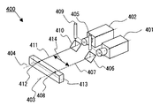
図4は2台のビデオカメラと2本のレーザーポインタを用いた本発明の実施例を示す。ビデオカメラ401、ビデオカメラ402は離間距離414で配置され、それぞれの光軸403、404を平行に配置して撮像対象である患部413を撮像する。レーザーポインタ405はハーフミラー406を介して光軸407でポイント輝点408を患部413に照射する。ハーフミラーによってレーザーポインタ光軸407はビデオカメラ401の光軸403と一致する構成にする。別のレーザーポインタ409はハーフミラー410を介して光軸411でポイント輝点412を患部413に照射する。ハーフミラーによってレーザーポインタ光軸411はビデオカメラ402の光軸404と一致する構成にする。この方法によりポイント輝点408は撮像対象患部413の位置を特定する輝点となる。輝点408は撮像対象患部を特定すると同時にポインタ光軸407がカメラ401の視点映像光軸であることから撮像される映像は輝点408がモニターディスプレイの表示中心となる。同じくポイント輝点412は撮像対象患部413の位置を特定する輝点となる。ポインタ光軸411がカメラ402の視点映像光軸であることから撮像される映像は輝点412がモニターディスプレイの表示中心となる。 FIG. 4 shows an embodiment of the present invention using two video cameras and two laser pointers. The
図5は、ビデオカメラ401,402で撮像された患部のディスプレイ上の映像を示す。説明上、ビデオカメラ401と402は同じサイズの撮像素子を用い、同じ焦点距離を持つレンズで撮像されたと仮定する。ビデオカメラ401で撮像された映像を501にビデオカメラ402で撮像された映像を502として示す。映像501は撮像対処患部503の位置を特定するポインタ輝点504を表示画面中心として表示される。説明上中心線509を仮想表示した。ビデオカメラ402で撮像された映像502は撮像対処患部503の位置を特定するポインタ輝点504は表示画面中心線509から表示画面上の座標距離は離れた位置に表示される。ここで映像501の患部503と位置特定ポイント504と輝点505の座標間距離507と図4におけるカメラ401とカメラ402実際の離間距離414の関係から患部503の水平方向の大きさ506が決まり、併せて垂直方向の大きさ508が求まる。図1による実施例では、図1においてカメラ101とカメラ102の映像情報が必要であるが、図4の実施方法例でカメラ401の映像情報のみで治療対象患部503の大きさが決定される。便宜上に映像502を表示したものだけに過ぎない。このことは、図1の実施例と同じ機能がカメラ401のみで得ることができることを示している。 FIG. 5 shows an image on the display of the affected area captured by the
図6は図4に示される実施方法例で得られた図5の映像情報化から、拡大された患部の詳細映像と患部の全体映像を1つのディスプレイ上に表示した例であり、これを600として示す。左側に拡大された患部の詳細映像部601、右側に患部の状況を把握出来る全体映像画面605を表示した。患部602の詳細把握には拡大した映像を1つのディスプレイ上の大部分に表示した例であり、全体状況の把握する全体映像は右側に配置し効率的な配置を実現し、詳細と全体を同時に視覚認識可能とし、かつ大きく視線を動かすことが無く円滑な治療動作が行える。図1の実施例と同じ機能がカメラ401のみで得ることが可能であることも示している。 FIG. 6 is an example in which an enlarged detailed image of the affected area and an entire image of the affected area are displayed on one display from the video informationization of FIG. 5 obtained in the implementation method example shown in FIG. As shown. A
図7は2台のビデオカメラと2本のレーザーポインタを用いた本発明の実施例を示す。ビデオカメラ701、ビデオカメラ702は離間距離714で配置され、それぞれの光軸703、704を平行に配置して撮像対象である患部713を撮像する。レーザーポインタ705はハーフミラー706を介して光軸707でポイント輝点708を患部713に照射する。ハーフミラー706によってレーザーポインタ光軸707はビデオカメラ701の光軸703と一致する構成にする。別のレーザーポインタ709はハーフミラー710を介して光軸711でポイント輝点712を患部713に照射する。レーザーポインタ光軸711はカメラ701の光軸が治療対象患部の所定距離716の位置で輝点708と輝点712が一点になるように交差させる。図7の例は治療対象患部の距離が所定距離716より短い状態を示しており輝点708と輝点712が一点に重ならず2つの輝点が表示される。矢印715は所定距離への移動方向を示している。実際にはビデオカメラシステムを患部より離す方向での移動調節となるが説明上の矢印715の表示となっている。矢印715の方向に患部との距離を調節し輝点708と輝点712が一点に重なる所定の距離位置に移動することが可能となる。この実施例により距離情報を得ることが可能となる。 FIG. 7 shows an embodiment of the present invention using two video cameras and two laser pointers. The
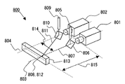
図8は2台のビデオカメラと2本のレーザーポインタを用いた本発明の実施例を示す。ビデオカメラ801、ビデオカメラ802は離間距離814で配置され、それぞれの光軸803、804を平行に配置して撮像対象である患部813を撮像する。レーザーポインタ805はハーフミラー806を介して光軸807でポイント輝点808を患部813に照射する。ハーフミラーによってレーザーポインタ光軸807はビデオカメラ801の光軸803と一致する構成にする。別のレーザーポインタ809はハーフミラー810を介して光軸811でポイント輝点812を患部813に照射する。レーザーポインタ光軸811はカメラ801の光軸が治療対象患部の所定距離815の位置で輝点808と輝点812が一点になるように交差させる。図8の例は治療対象患部の距離が図7における所定距離716に一致した状態を示している。レーザーポインタ805,809の照射光軸が所定距離815で一点に交差して、それぞれの輝点が1点(808,812)になる状態を示す。 FIG. 8 shows an embodiment of the present invention using two video cameras and two laser pointers. The
図9は図7及び図8の状態の患部のカメラ801映像を示す。図7の状態の患部映像を901に、図8の状態の患部映像を902に示す。映像901では患部903上の輝点904,905が2点となっており、所定距離と距離が異なっていることがわかる。映像902では患部への距離が所定距離にあり輝点904と905が1点に重なっている。 FIG. 9 shows a
図10は2台のビデオカメラと2本のレーザーポインタを用いた本発明の実施例を示す。ビデオカメラ1001、ビデオカメラ1002は離間距離1013で配置され、それぞれの光軸1003、1004を平行に配置して撮像対象である患部1012を撮像する。レーザーポインタ1005はハーフミラー1006を介して光軸1007でポイント輝点1008を患部1013に照射する。ハーフミラーによってレーザーポインタ光軸1007はビデオカメラ1001の光軸1003と一致する構成にする。別のレーザーポインタ1009は照射光軸1010でポイント輝点1011を患部1012に照射する。この時カメラ光軸1003、1004及びレーザーポインタの光軸1010は一つの平面を構成する。レーザーポインタ光軸1010はカメラ1001の光軸1003が治療対象患部の所定距離1015の位置で輝点1008と輝点1012が一点になるように交差させる。図10の例は治療対象患部の距離が所定距離1015より短い状態を示しており輝点1008と輝点1001が一点に重ならず2つの輝点を表示している。矢印1014は所定距離への移動方向を示している。矢印1014の方向に患部との距離を調節し輝点1008と輝点1011が一点に重なる所定の距離位置に移動することが可能となる。この実施例により距離情報を得ることが可能となる。矢印1014は所定距離への移動方向を示している。 FIG. 10 shows an embodiment of the present invention using two video cameras and two laser pointers. The
図11は図10の本発明実施例でカメラ1001の患部撮影映像を示す。図10の状態の患部映像1101は治療対象患部の距離が所定距離1015より短い状態を示している。映像1101では患部1103上の輝点11104,1105が2つの輝点として表示されており、所定距離と距離が異なっていることがわかる。図10の矢印1014方向に所定距離に調節を行うことで患部への距離が所定距離となり輝点1104と1105を1点に重ね所定の距離になる。矢印1014は所定距離への移動方向を示している。この実施例により距離情報を得ることが可能となる。映像中心線1106は説明上表示した。 FIG. 11 shows an image of an affected area photographed by the
図12の実施例は、2台のビデオカメラと3本のレーザーポインタを用いた本発明の実施例を示す。ビデオカメラ1201、ビデオカメラ1202は離間距離1213で配置され、それぞれの光軸1203、1204を平行に配置して撮像対象である患部1212を撮像する。レーザーポインタ1205はハーフミラー1206を介して照射光軸1207でポイント輝点1208を患部1213に照射する。ハーフミラー1206によってレーザーポインタ光軸1207はビデオカメラ1201の光軸1203と一致する構成にする。2本目のレーザーポインタ1209は照射光軸1210でポイント輝点1211を患部1212に照射する。この時カメラ光軸1203、1204及びレーザーポインタの光軸1210は一つの平面を構成する。レーザーポインタ光軸1210はカメラ1201の光軸1203が治療対象患部の所定距離1219の位置で輝点1208と輝点1212が一点になるように交差させる。この前記2本とは別のレーザーポインタを前記カメラ光軸1203、1204及びレーザーポインタの光軸1210が構成する平面に対し距離1216を離間して配置し照射光軸1217でポイント輝点1218を患部1212に照射する。この時、照射光軸1217は前記構成平面に平行となる様に構成する。図12の例では所定距離より小さい設定の距離1219を想定してある。この場合の輝点1208と輝点1211は2つの輝点として表示され、レーザーポインタ1215で照射される輝点1218は、これら輝点1208,1211と距離1216離れた位置に表示される。矢印1214は前記所定距離への移動方向を示している。矢印1214の方向に患部との距離を調節し輝点1208と輝点1212が一点に重なる所定の距離位置に移動し、距離情報を得ることが可能となる。矢印1214は所定距離への移動調整方向を示している。 The embodiment of FIG. 12 shows an embodiment of the present invention using two video cameras and three laser pointers. The
図13は図12の例のカメラ1201で撮像した映像を示す。映像1300は患部1301上にポインタ輝点1302,1303,1304が表示される。輝点1302は図12におけるポインタ1205による照射輝点、輝点1303は同じくポインタ1209による照射輝点、輝点1305はポインタ1215による照射輝点である。1300として表示された映像において輝点1303(1302)と輝点1304の垂直方向の座標1306は図12の距離1216に準拠しており、垂直方向の患部大きさ1307及び水平方向の患部の大きさ1308が決定されるポインタ輝点1302と輝点1303は2つ輝点として表示されているがこれは図12における距離1219が所定の距離よりも小さいことに起因する。このポインタ輝点1302、1303の輝点間距離座標1305が最小になるように、患部との距離を調整することで所定の距離に患部を配置することが可能となる。よって、この実施例で患部の大きさ及び距離の情報を得ることが可能となる。 FIG. 13 shows an image captured by the
図14の実施例は、2台のビデオカメラと3本のレーザーポインタを用いた本発明の実施例を示す。ビデオカメラ1401、ビデオカメラ1402は離間距離1414で配置され、それぞれの光軸1403、1404を平行に配置して撮像対象である患部1415を撮像する。レーザーポインタ1405は照射光軸1406でポイント輝点1407を患部1415に照射する。別のレーザーポインタ1408は照射光軸1409でポイント輝点1410を患部1415に照射する。この時カメラ光軸1403、1404及びレーザーポインタの光軸1406、1409は一つの平面を構成する。前記2本のレーザーポインタとは別のレーザーポインタ1411による照射輝点1413がポインタ1405による照射輝点1407と所定距離で1点に重なる様に前記平面と斜めに交差させる。例として照射光軸1412と照射光軸1406は前記平面に直交する平面を形成する。図14での患部とビデオカメラシステムとの距離1417は所定の距離より小さい時の設定例であり、輝点1407,輝点1413は2つの輝点と表示される。矢印1416方向に距離を調節し所定距離になると輝点1407,輝点1413は1つの輝点とが重なり表示される。この実施例により距離情報を得ることが可能となる。 The embodiment of FIG. 14 shows an embodiment of the present invention using two video cameras and three laser pointers. The
図15は図14の実施例の映像表示を1500として示した。表示1500の左側に患部1503の拡大映像、右側に患部1503の全体映像を同一ディスプレイ上に表示した。患部1503に照射された輝点1504,1505,1506の水平方向の座標1507から患部の大きさ1509,1510を得る。また輝点1504(1505)と輝点1506の座標位置から患部との距離も得ることができる。 FIG. 15 shows the video display of the embodiment of FIG. The enlarged image of the affected
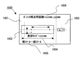
図16は請求項2〜7の手段によって得られた患部の大きさまたは距離情報を患部映像画面に加えて表示する実施例を示した。図16の表示例は図14の構成を例としている。 FIG. 16 shows an embodiment in which the size or distance information of the affected area obtained by the means of claims 2 to 7 is displayed in addition to the affected area video screen. The display example of FIG. 16 uses the configuration of FIG. 14 as an example.
図17の実施例は、2台のビデオカメラと1本のレーザーポインタを用いた本発明の実施例を示す。ビデオカメラ1701、ビデオカメラ1702は互いの光軸1703,1704が一つの平面を成し、所定の距離1711で交差する構成を採る。レーザーポインタ1705はカメラ1701の前面に配したハーフミラーを介在しカメラ光軸1703と一致する照射光軸1707で照射ポイント輝点1708を患部1709に照射する。カメラ光軸1703,1704は患部との所定距離1710で交差する形態を採る。レーザーポインタ1705はハーフミラー1706を介して照射光軸1707でポイント輝点1708を患部1709に照射する。照射光軸は1707はこの形態によりカメラ光軸1703と一致する構造を採る。 The embodiment of FIG. 17 shows an embodiment of the present invention using two video cameras and one laser pointer. The
図17の構成による実施例でのカメラ1701、1702での撮像映像を図18に示す。患部1709が所定の距離1710より近い位置にあるときのカメラ1701,1702による撮像映像をそれぞれ1801、1802に示し、患部1709が所定の距離1710の位置にあるときのカメラ1701,1702による撮像映像をそれぞれ1803、1804として示した。映像1802において輝点1806と映像中心線1807との表示座標のズレ1808が生ずる。患部1709が所定の距離1711の位置にあるときのカメラ1702による撮像映像の1804では前記のズレは無くなる。尚、映像中心線1807は画像認識上の仮想線である。 Images captured by the
図19は本発明実施例として無影灯照明とカメラシステムを組み合わせた無影灯ビデオカメラ装置1900である。複数の照明灯1901,1902,1903,1904,1905を配し歯科治療における手術者覗き込み動作の影、手または指の影、手術器具等による照明障害を少なくする例である。図19の例はビデオカメラ1906,1907,1908の3台、レーザーポインタ2台とハーフミラーを前記ビデオカメラの前面に配置した例である。 FIG. 19 shows a surgical light
100 本発明装置例
101 ビデオカメラ
102 ビデオカメラ
103 ビデオカメラ光軸
104 ビデオカメラ光軸
105 レーザーポインタ
106 ハーフミラー
107 レーザーポインタ光軸
108 レーザーポインタ輝点
109 治療対象患部
110 ビデオカメラ間距離
201 ビデオカメラ映像
202 ビデオカメラ映像
203 治療対象患部
204 レーザーポインタ輝点
205 ビデオカメラ映像中心線
206 治療対象患部寸法
207 治療対象患部寸法
208 レーザーポインタ輝点間距離
209 仮想の治療対象患部
210 仮想のレーザーポインタ輝点
300 治療対象患部映像表示例
301 治療対象患部詳細拡大映像表示部
302 治療対象患部
303 レーザーポインタ輝点
304 治療対象患部全体映像表示部
400 本発明装置例
401 ビデオカメラ
402 ビデオカメラ
403 ビデオカメラ光軸
404 ビデオカメラ光軸
405 レーザーポインタ
406 ハーフミラー
407 レーザーポインタ光軸
408 レーザーポインタ輝点
409 レーザーポインタ
410 ハーフミラー
411 レーザーポインタ光軸
412 レーザーポインタ輝点
413 治療対象患部
414 ビデオカメラ間距離
501 ビデオカメラ映像
502 ビデオカメラ映像
503 治療対象患部
504 レーザーポインタ輝点
505 レーザーポインタ輝点
506 レーザーポインタ輝点間距離
507 治療対象患部寸法
508 治療対象患部寸法
509 ビデオカメラ映像中心線
510 ビデオカメラ映像中心線
600 治療対象患部映像表示例
601 治療対象患部詳細拡大映像表示部
602 治療対象患部
603 レーザーポインタ輝点
604 レーザーポインタ輝点
605 治療対象患部全体映像表示部
700 本発明装置例
701 ビデオカメラ
702 ビデオカメラ
703 ビデオカメラ光軸
704 ビデオカメラ光軸
705 レーザーポインタ
706 ハーフミラー
707 レーザーポインタ光軸
708 レーザーポインタ輝点
709 レーザーポインタ
710 ハーフミラー
711 レーザーポインタ光軸
712 レーザーポインタ輝点
713 治療対象患部
714 ビデオカメラ間距離
715 距離移動調節
716 治療対象患部との所定距離
800 本発明装置例
801 ビデオカメラ
802 ビデオカメラ
803 ビデオカメラ光軸
804 ビデオカメラ光軸
805 レーザーポインタ
806 ハーフミラー
807 レーザーポインタ光軸
808 レーザーポインタ輝点
809 レーザーポインタ
810 ハーフミラー
811 レーザーポインタ光軸
812 レーザーポインタ輝点
813 治療対象患部
814 ビデオカメラ間距離
815 治療対象患部との所定距離
901 ビデオカメラ映像
902 ビデオカメラ映像
903 治療対象患部
904 レーザーポインタ輝点
905 レーザーポインタ輝点
1000 本発明装置例
1001 ビデオカメラ
1002 ビデオカメラ
1003 ビデオカメラ光軸
1004 ビデオカメラ光軸
1005 レーザーポインタ光軸
1006 ハーフミラー
1007 レーザーポインタ
1008 レーザーポインタ輝点
1009 レーザーポインタ
1010 レーザーポインタ光軸
1011 レーザーポインタ輝点
1012 治療対象患部
1013 ビデオカメラ間距離
1014 距離移動調節
1015 治療対象患部との所定距離
1101 治療対象患部映像表示部
1102 治療対象患部映像表示部
1103 治療対象患部
1104 レーザーポインタ輝点
1105 レーザーポインタ輝点
1106 仮想の映像中心線
1200 本発明装置例
1201 ビデオカメラ
1202 ビデオカメラ
1203 ビデオカメラ光軸
1204 ビデオカメラ光軸
1205 レーザーポインタ
1206 ハーフミラー
1207 レーザーポインタ光軸
1208 レーザーポインタ輝点
1209 レーザーポインタ
1210 レーザーポインタ光軸
1211 レーザーポインタ輝点
1212 治療対象患部
1213 ビデオカメラ間距離
1214 距離移動調節
1215 レーザーポインタ
1216 カメラ光軸との離間距離
1217 レーザーポインタ光軸
1218 レーザーポインタ輝点
1219 治療対象患部との所定距離
1300 治療対象患部映像表示
1301 治療対象患部
1302 レーザーポインタ輝点
1303 レーザーポインタ輝点
1304 レーザーポインタ輝点
1305 レーザーポインタ輝点距離
1306 レーザーポインタ輝点距離
1307 治療対象患部寸法
1308 治療対象患部寸法
1400 本発明装置例
1401 ビデオカメラ
1402 ビデオカメラ
1403 ビデオカメラ光軸
1404 ビデオカメラ光軸
1405 レーザーポインタ
1406 レーザーポインタ光軸
1407 レーザーポインタ輝点
1408 レーザーポインタ
1409 レーザーポインタ光軸
1410 レーザーポインタ輝点
1411 レーザーポインタ
1412 レーザーポインタ光軸
1413 レーザーポインタ輝点
1414 ビデオカメラ間距離
1415 治療対象患部
1416 距離移動調節
1417 治療対象患部との距離
1500 治療対象患部映像表示例
1501 治療対象患部詳細拡大映像表示部
1502 治療対象患部全体映像表示部
1503 治療対象患部
1504 レーザーポインタ輝点
1505 レーザーポインタ輝点
1506 レーザーポインタ輝点
1507 レーザーポインタ輝点間距離
1508 レーザーポインタ輝点間距離
1509 治療対象患部寸法
1510 治療対象患部寸法
1600 本発明表示例
1601 治療対象患部詳細拡大映像表示部
1602 治療対象患部
1603 治療対象患部全体映像表示部
1604 治療対象患部寸法表示例
1605 治療対象患部寸法表示例
1606 治療対象患部寸法表示例
1700 本発明装置例
1701 ビデオカメラ
1702 ビデオカメラ
1703 ビデオカメラ光軸
1704 ビデオカメラ光軸
1705 レーザーポインタ
1706 ハーフミラー
1707 レーザーポインタ光軸
1708 レーザーポインタ輝点
1709 治療対象患部
1710 治療対象患部との所定距離
1801 治療対象患部映像表示部
1802 治療対象患部映像表示部
1803 治療対象患部映像表示部
1804 治療対象患部映像表示部
1805 治療対象患部
1806 レーザーポインタ輝点
1807 ビデオカメラ映像中心線
1808 レーザーポインタ輝点距離
1900 本発明装置例
1901 照明灯
1902 照明灯
1903 照明灯
1904 照明灯
1905 照明灯
1906 ビデオカメラ
1907 ビデオカメラ
1908 ビデオカメラ
1909 治療対象患部DESCRIPTION OF SYMBOLS 100 Example of this invention 101 Video camera 102 Video camera 103 Video camera optical axis 104 Video camera optical axis 105 Laser pointer 106 Half mirror 107 Laser pointer optical axis 108 Laser pointer bright spot 109 Treatment target affected part 110 Distance between video cameras 201 Video camera image 202 Video camera image 203 Treatment target affected area 204 Laser pointer bright spot 205 Video camera image center line 206 Treatment target affected area dimension 207 Treatment target affected area dimension 208 Laser pointer bright spot distance 209 Virtual treatment target affected area 210 Virtual laser pointer bright spot 300 Treatment target affected part image display example 301 Treatment target affected part detail enlarged image display part 302 Treatment target affected part 303 Laser pointer bright spot 304 Treatment target affected part whole picture display part 400 Example apparatus 401 of the present invention O Camera 402 Video camera 403 Video camera optical axis 404 Video camera optical axis 405 Laser pointer 406 Half mirror 407 Laser pointer optical axis 408 Laser pointer bright spot 409 Laser pointer 410 Half mirror 411 Laser pointer optical axis 412 Laser pointer bright spot 413 Treatment target affected area 414 Video camera distance 501 Video camera image 502 Video camera image 503 Treatment target affected area 504 Laser pointer bright spot 505 Laser pointer bright spot 506 Laser pointer bright spot distance 507 Treatment target affected dimension 508 Treatment target affected dimension 509 Video camera video center line 510 Video Camera Video Center Line 600 Treatment Target Affected Part Video Display Example 601 Treatment Target Affected Part Detailed Enlarged Video Display Part 602 Treatment Target Affected Part 603 Laser Pointer Brightness 604 Laser pointer bright spot 605 Treatment target whole body image display part 700 Example apparatus 701 of the present invention Video camera 702 Video camera 703 Video camera optical axis 704 Video camera optical axis 705 Laser pointer 706 Half mirror 707 Laser pointer optical axis 708 Laser pointer bright spot 709 Laser pointer 710 Half mirror 711 Laser pointer optical axis 712 Laser pointer bright spot 713 Treatment target affected area 714 Distance between video cameras 715 Distance movement adjustment 716 Predetermined distance 800 from treatment target affected area 800 Example apparatus 801 Video camera 802 Video camera 803 Video Camera optical axis 804 Video camera optical axis 805 Laser pointer 806 Half mirror 807 Laser pointer optical axis 808 Laser pointer bright spot 809 Laser pointer 81 0 Half mirror 811 Laser pointer optical axis 812 Laser pointer bright spot 813 Treatment target affected area 814 Distance between video cameras 815 Predetermined distance from treatment target affected area 901 Video camera video 902 Video camera video 903 Treatment target affected area 904 Laser pointer bright spot 905 Laser pointer Bright spot 1000 Example apparatus 1001 of the present invention Video camera 1002 Video camera 1003 Video camera optical axis 1004 Video camera optical axis 1005 Laser pointer optical axis 1006 Half mirror 1007 Laser pointer 1008 Laser pointer bright spot 1009 Laser pointer 1010 Laser pointer optical axis 1011 Laser pointer Bright spot 1012 Treatment target affected area 1013 Distance between video cameras 1014 Distance movement adjustment 1015 Predetermined distance 1101 with treatment target affected area Treatment target affected part image display unit 1102 Treatment target affected part image display part 1103 Treatment target affected part 1104 Laser pointer bright spot 1105 Laser pointer bright spot 1106 Virtual image center line 1200 Example apparatus 1201 Video camera 1202 Video camera 1203 Video camera optical axis 1204 Video camera optical axis 1205 Laser pointer 1206 Half mirror 1207 Laser pointer optical axis 1208 Laser pointer bright spot 1209 Laser pointer 1210 Laser pointer optical axis 1211 Laser pointer bright spot 1212 Treatment target affected area 1213 Distance between video cameras 1214 Distance adjustment 1215 Laser pointer 1216 Distance 1217 from camera optical axis Laser pointer optical axis 1218 Laser pointer bright spot 1219 Predetermined distance 13 from the affected area to be treated 00 Treatment target affected part image display 1301 Treatment target affected part 1302 Laser pointer bright spot 1303 Laser pointer bright spot 1304 Laser pointer bright spot 1305 Laser pointer bright spot distance 1306 Laser pointer bright spot distance 1307 Treatment target affected part dimension 1308 Treatment target affected part dimension 1400 The present invention Example apparatus 1401 Video camera 1402 Video camera 1403 Video camera optical axis 1404 Video camera optical axis 1405 Laser pointer 1406 Laser pointer optical axis 1407 Laser pointer bright spot 1408 Laser pointer 1409 Laser pointer optical axis 1410 Laser pointer bright spot 1411 Laser pointer 1412 Laser pointer 1412 Laser pointer Optical axis 1413 Laser pointer bright spot 1414 Distance 1415 between video cameras Treatment target affected area 1416 Distance shift Adjustment 1417 Distance to treatment target disease 1500 Treatment target disease image display example 1501 Treatment target disease detail enlarged image display unit 1502 Treatment target whole image display unit 1503 Treatment target disease part 1504 Laser pointer bright spot 1505 Laser pointer bright spot 1506 Laser pointer bright spot Point 1507 Distance between laser pointer luminescent spots 1508 Distance between laser pointer luminescent spots 1509 Treatment target affected part dimension 1510 Treatment target affected part dimension 1600 Display example 1601 Treatment target affected part detail enlarged image display part 1602 Treatment target affected part 1603 Treatment target affected part whole picture display Unit 1604 Treatment target affected part dimension display example 1605 Treatment target affected part dimension display example 1606 Treatment target affected part dimension display example 1700 Invention apparatus example 1701 Video camera 1702 Video camera 1703 Video camera optical axis 1704 B Deo camera optical axis 1705 Laser pointer 1706 Half mirror 1707 Laser pointer optical axis 1708 Laser pointer bright spot 1709 Treatment target affected part 1710 Predetermined distance 1801 treatment target affected part video display part 1802 Treatment target affected part video display part 1803 Treatment target affected part video Display unit 1804 Treatment target affected part image display unit 1805 Treatment target affected part 1806 Laser pointer bright spot 1807 Video camera video center line 1808 Laser pointer bright spot distance 1900 Example apparatus 1901 Illumination lamp 1902 Illumination lamp 1903 Illumination lamp 1904 Illumination lamp 1905 Illumination lamp 1906 Video camera 1907 Video camera 1908 Video camera 1909
Claims (11)
Priority Applications (1)
| Application Number | Priority Date | Filing Date | Title |
|---|---|---|---|
| JP2010285109A JP2012120812A (en) | 2010-12-06 | 2010-12-06 | Dental support system using video camera for dental treatment |
Applications Claiming Priority (1)
| Application Number | Priority Date | Filing Date | Title |
|---|---|---|---|
| JP2010285109A JP2012120812A (en) | 2010-12-06 | 2010-12-06 | Dental support system using video camera for dental treatment |
Publications (1)
| Publication Number | Publication Date |
|---|---|
| JP2012120812A true JP2012120812A (en) | 2012-06-28 |
Family
ID=46502908
Family Applications (1)
| Application Number | Title | Priority Date | Filing Date |
|---|---|---|---|
| JP2010285109A Pending JP2012120812A (en) | 2010-12-06 | 2010-12-06 | Dental support system using video camera for dental treatment |
Country Status (1)
| Country | Link |
|---|---|
| JP (1) | JP2012120812A (en) |
Cited By (4)
| Publication number | Priority date | Publication date | Assignee | Title |
|---|---|---|---|---|
| KR20170096810A (en) | 2016-02-17 | 2017-08-25 | 삼성전자주식회사 | Remote image transmission system, display apparatus and guide displaying method of thereof |
| JP2018175722A (en) * | 2017-04-20 | 2018-11-15 | 株式会社モリタ東京製作所 | Oral cavity imaging system |
| WO2019044124A1 (en) | 2017-09-04 | 2019-03-07 | 大樹 梶田 | Multiple-viewpoint video image viewing system and camera system |
| WO2020130364A1 (en) * | 2018-12-18 | 2020-06-25 | 주식회사 제노레이 | Device and method for managing medical image data and treatment data |
-
2010
- 2010-12-06 JP JP2010285109A patent/JP2012120812A/en active Pending
Cited By (7)
| Publication number | Priority date | Publication date | Assignee | Title |
|---|---|---|---|---|
| KR20170096810A (en) | 2016-02-17 | 2017-08-25 | 삼성전자주식회사 | Remote image transmission system, display apparatus and guide displaying method of thereof |
| KR102508831B1 (en) * | 2016-02-17 | 2023-03-10 | 삼성전자주식회사 | Remote image transmission system, display apparatus and guide displaying method of thereof |
| JP2018175722A (en) * | 2017-04-20 | 2018-11-15 | 株式会社モリタ東京製作所 | Oral cavity imaging system |
| WO2019044124A1 (en) | 2017-09-04 | 2019-03-07 | 大樹 梶田 | Multiple-viewpoint video image viewing system and camera system |
| US20200268471A1 (en) * | 2017-09-04 | 2020-08-27 | Hiroki Kajita | Multiple-viewpoint video image viewing system and camera system |
| US11678950B2 (en) * | 2017-09-04 | 2023-06-20 | Hiroki Kajita | Multiple-viewpoint video image viewing system and camera system |
| WO2020130364A1 (en) * | 2018-12-18 | 2020-06-25 | 주식회사 제노레이 | Device and method for managing medical image data and treatment data |
Similar Documents
| Publication | Publication Date | Title |
|---|---|---|
| EP2903551B1 (en) | Digital system for surgical video capturing and display | |
| US20240080433A1 (en) | Systems and methods for mediated-reality surgical visualization | |
| JP6254186B2 (en) | Endoscope with multi-camera system for minimally invasive surgery | |
| JP4398352B2 (en) | Medical stereoscopic imaging device | |
| US10838189B2 (en) | Operating microscope having an image sensor and a display, and method for operating an operating microscope | |
| JP6654006B2 (en) | Medical observation device | |
| JP2006158452A5 (en) | ||
| JP7095693B2 (en) | Medical observation system | |
| CN112654280A (en) | Medical observation system, medical observation apparatus, and medical observation method | |
| US20210019921A1 (en) | Image processing device, image processing method, and program | |
| JP2012120812A (en) | Dental support system using video camera for dental treatment | |
| JPWO2018179681A1 (en) | Medical observation device and observation visual field correction method | |
| US20200045293A1 (en) | Medical observation apparatus | |
| JPH11318936A (en) | Microscopic device for operation | |
| JP2014228851A (en) | Endoscope device, image acquisition method, and image acquisition program | |
| JP6935389B2 (en) | Medical stereoscopic observation device, medical stereoscopic observation method, and program | |
| US11102424B2 (en) | Medical observation apparatus and medical observation system | |
| JP7143099B2 (en) | medical observation system | |
| WO2018168578A1 (en) | Imaging device, video signal processing device, and video signal processing method | |
| WO2017145606A1 (en) | Image processing device, image processing method, and endoscope system | |
| KR20080027187A (en) | Endoscope for providing 3d image data | |
| JP7160042B2 (en) | Image processing device, image processing method and image processing program | |
| US20200306003A1 (en) | Medical control apparatus and medical observation system | |
| JP2017037238A (en) | Medical observation device, control unit, and method and program for operating control unit | |
| WO2018043205A1 (en) | Medical image processing device, medical image processing method, and program |