JP2012117563A - Mechanism for restricting movement in one direction - Google Patents

Mechanism for restricting movement in one direction Download PDF

Info

Publication number
JP2012117563A
JP2012117563A JP2010265656A JP2010265656A JP2012117563A JP 2012117563 A JP2012117563 A JP 2012117563A JP 2010265656 A JP2010265656 A JP 2010265656A JP 2010265656 A JP2010265656 A JP 2010265656A JP 2012117563 A JP2012117563 A JP 2012117563A
Authority
JP
Japan
Prior art keywords
roller member
relative
relative movement
protrusion
pressing means
Prior art date
Legal status (The legal status is an assumption and is not a legal conclusion. Google has not performed a legal analysis and makes no representation as to the accuracy of the status listed.)
Withdrawn
Application number
JP2010265656A
Other languages
Japanese (ja)
Inventor
Wataru Honda
渉 本田
Current Assignee (The listed assignees may be inaccurate. Google has not performed a legal analysis and makes no representation or warranty as to the accuracy of the list.)
TOK Bearing Co Ltd
Original Assignee
TOK Bearing Co Ltd
Priority date (The priority date is an assumption and is not a legal conclusion. Google has not performed a legal analysis and makes no representation as to the accuracy of the date listed.)
Filing date
Publication date
Application filed by TOK Bearing Co Ltd filed Critical TOK Bearing Co Ltd
Priority to JP2010265656A priority Critical patent/JP2012117563A/en
Priority to CN2011103865743A priority patent/CN102562780A/en
Publication of JP2012117563A publication Critical patent/JP2012117563A/en
Withdrawn legal-status Critical Current

Links

Images

Landscapes

  • Closing And Opening Devices For Wings, And Checks For Wings (AREA)
  • Electrophotography Configuration And Component (AREA)

Abstract

PROBLEM TO BE SOLVED: To restrict the movement of a component member in a relative motion only when moving in a specific direction, and to allow a smooth movement without roughness when moving in an opposite direction.SOLUTION: A mechanism for restricting a movement in one direction includes pressing means 6, 9 for pressing a first projection 8 provided at a first member 1b in a relative motion, and the second projection 4 provided at the second member 2 in a relative motion, to the direction opposing to each other. The constitution is made such that the elastic force of the pressing means 6, 9 causes the second projection 4 pass over the first projection 8, and both members 1b, 2 move relatively. The position holding the second projection 4 becomes different when the direction of the relative movement is in one of the direction A and from when in the other of the direction B. By this constitution, the values of elastic forces working on the first and the second 4, 8 are varied.

Description

本発明は、相対移動する移動物体間の移動方向が一方向のときのみ、その移動に大きな抵抗を付与する一方向移動制限機構に関する。   The present invention relates to a one-way movement limiting mechanism that gives a large resistance to movement only when the movement direction between moving objects that move relatively is one direction.

相対移動する二部材間で、一定以上の外力を作用させない限り所定の位置を維持する移動制限機構が知られている。
例えば、特許文献1に記載された、回転ダンパにおける自立機構は、開放した開閉蓋が倒れないで起立するようにするための移動制限機構である。
その具体的構造は、次のとおりである。
開閉蓋の回転軸の外周に形成した軸方向溝に、回転軸の外周面から突出する第1ニードルを設けるとともに、この回転軸を囲む筒状の外枠にはスリットを設け、このスリットには、外枠の内周面から内側へ突出した第2ニードルを設けている。また、上記外枠には、第2ニードルを内側へ付勢するばね手段を設けている。
A movement limiting mechanism is known that maintains a predetermined position unless an external force of a certain level or more is applied between two members that move relative to each other.
For example, a self-supporting mechanism in a rotary damper described in Patent Document 1 is a movement limiting mechanism for allowing an opened opening / closing lid to stand up without falling down.
Its specific structure is as follows.
A first needle protruding from the outer peripheral surface of the rotating shaft is provided in an axial groove formed on the outer periphery of the rotating shaft of the opening / closing lid, and a slit is provided in a cylindrical outer frame surrounding the rotating shaft. A second needle protruding inward from the inner peripheral surface of the outer frame is provided. The outer frame is provided with spring means for urging the second needle inward.

上記外枠に対して回転軸を回転させる過程で、回転軸に設けた第1ニードルと第2ニードルとが接触したときには、上記ばね手段に弾性力によるトルクに抗して回転させるようにする。つまり、上記弾性力によるトルクに打ち勝つ力を作用させなければ、上記第1ニードルと第2ニードルとの接触位置を越えて回転軸が回転することがないので、回転軸に取り付けた開閉蓋などを自立させることができるというものである。   In the process of rotating the rotary shaft with respect to the outer frame, when the first needle and the second needle provided on the rotary shaft come into contact with each other, the spring means is rotated against torque caused by elastic force. That is, unless a force that overcomes the torque due to the elastic force is applied, the rotating shaft does not rotate beyond the contact position between the first needle and the second needle. It can be made independent.

特許第2739164号公報Japanese Patent No. 2739164

上記した自立機構では、外枠と回転軸とが相対回転するとき、回転軸側の第1ニードルと外枠側の第2ニードルとが接触した場合に、上記弾性力によるトルクに打ち勝つ外力を作用させなければ、その位置から回転軸を回転させることができないが、このような外力を必要とするのは、回転軸の回転方向によらない。つまり、回転軸をどちらの方向に回転させる場合であっても、第1ニードルと第2ニードルとが接触した位置を越えて回転軸を回転させるためには、所定の位置において大きな力が必要になる。
例えば、蓋を全開して起立させたとき、その蓋は意識的に閉じる方向の力を作用させない限り、上記第1ニードルと第2ニードルとの接触位置を越えて自重で落下してしまうことがない。
In the above self-supporting mechanism, when the outer frame and the rotation shaft rotate relative to each other, when the first needle on the rotation shaft side contacts the second needle on the outer frame side, an external force that overcomes the torque generated by the elastic force is applied. Otherwise, the rotating shaft cannot be rotated from that position, but the reason why such an external force is required does not depend on the rotating direction of the rotating shaft. That is, no matter which direction the rotating shaft is rotated, a large force is required at a predetermined position in order to rotate the rotating shaft beyond the position where the first needle and the second needle are in contact with each other. Become.
For example, when the lid is fully opened and stood up, the lid may fall by its own weight beyond the contact position between the first needle and the second needle unless a force in the direction of intentionally closing is applied. Absent.

しかし、蓋を開ける場合にも、閉じる場合と同様に、第1ニードルと第2ニードルとの接触位置を超えるため、上記弾性力によるトルクに打ち勝つ大きさの力が必要である。
このように、上記従来の移動制限機構では、蓋を閉めるときだけでなく、開けるときにも所定の位置で、上記弾性力によるトルクに打ち勝つ大きな力を作用させなければならなかった。実際には、開けた蓋が勝手に閉まることを防止したいのであって、開ける時に抵抗を付与する必要はないが、上記従来の制限機構では、制限する必要がない方向の移動であっても、蓋などの部材を、違和感なくスムーズに移動させることができないという問題があった。
However, when the lid is opened, as in the case of closing, the contact position between the first needle and the second needle is exceeded, so that a force large enough to overcome the torque by the elastic force is required.
Thus, in the conventional movement restriction mechanism, not only when the lid is closed, but also when the lid is opened, a large force that overcomes the torque generated by the elastic force must be applied at a predetermined position. Actually, it is necessary to prevent the opened lid from being closed on its own, and it is not necessary to provide resistance when opening the lid, but with the conventional restriction mechanism, even if the movement is in a direction that does not need to be restricted, There was a problem that a member such as a lid could not be moved smoothly without a sense of incongruity.

この発明の目的は、相対移動する部材が、特定の方向へ移動する時にのみ、その移動を制限し、反対の方向への移動する時には違和感のないスムーズな移動を可能にする一方向移動制限機構を提供することである。   An object of the present invention is to limit a movement of a relative moving member only when moving in a specific direction, and to allow a smooth movement without a sense of incongruity when moving in the opposite direction. Is to provide.

第1の発明は、第1相対移動部材と、この第1相対移動部材と相対移動する第2相対移動部材と、第1、第2相対移動部材には互いに対向する面に設けた第1、第2突出部と、上記第1相対移動部材あるいは第2相対移動部材のいずれか一方または双方に備え、上記第1突出部あるいは第2突出部を対向面側へ押圧する弾性力を作用させる押圧手段と、上記第2相対移動部材に設け、移動方向に隣接する第1保持位置と第2保持位置を設けるとともに上記第2突出部を上記第1、第2保持位置の範囲内で移動可能に保持する保持部とを備えたものである。   The first invention includes a first relative movement member, a second relative movement member that moves relative to the first relative movement member, and first and second relative movement members that are provided on surfaces facing each other. A pressing member that is provided in one or both of the second protruding portion and the first relative moving member or the second relative moving member, and that exerts an elastic force that presses the first protruding portion or the second protruding portion toward the opposite surface. And a first holding position and a second holding position adjacent to each other in the moving direction, and the second projecting portion is movable within the range of the first and second holding positions. And a holding unit for holding.

そして、第1の発明は、上記第1相対移動部材を第2相対移動部材に対して一方の方向に相対移動させる移動力を付与したとき、上記第2突出部が上記第1保持位置に位置しながら上記押圧手段の弾性力に抗して第1突出部を乗り越え、上記第1相対移動部材を第2相対移動部材に対して他の方向に相対移動させる移動力を付与したとき、上記第2突出部が上記第2保持位置に位置しながら上記押圧手段の弾性力に抗して第1突出部を乗り越え、上記第1相対移動部材が上記一方の方向に相対移動して上記第2突出部が第1突出部を乗り越える際に作用する弾性力よりも、上記第1相対移動部材が上記他方の方向に相対移動して上記第2突出部が第1突出部を乗り越える際に作用する弾性力の方が大きくなる構成にしたことを特徴とする。   According to the first aspect of the present invention, when the moving force for moving the first relative movement member relative to the second relative movement member in one direction is applied, the second protrusion is positioned at the first holding position. While moving over the first protrusion against the elastic force of the pressing means and applying a moving force that moves the first relative moving member relative to the second relative moving member in the other direction, the first The two protrusions move over the first protrusion against the elastic force of the pressing means while being positioned at the second holding position, and the first relative movement member moves relative to the one direction to move the second protrusion. Relative movement of the first relative movement member relative to the other direction rather than the elastic force acting when the part gets over the first protrusion, and the elasticity acting when the second protrusion gets over the first protrusion The feature is that the force is greater.

第2の発明は、上記押圧手段が、少なくとも、第1突出部に弾性力を作用させる第1押圧手段からなることを特徴とする。   The second invention is characterized in that the pressing means comprises at least first pressing means for applying an elastic force to the first protrusion.

第3の発明は、第1または第2の発明を前提とし、上記押圧手段が、上記第1押圧手段と、第2相対移動部材に設けるとともに第1押圧手段よりもばね力を小さくした第2押圧手段とからなり、この第2押圧手段は、第2突出部が第1保持位置にあるとき、第2突出部に対してばね力を作用させる構成にしたことを特徴とする。   3rd invention presupposes 1st or 2nd invention, and the said press means provided the said 1st press means and the 2nd relative movement member, and 2nd made the spring force smaller than the 1st press means. The second pressing means is characterized in that a spring force is applied to the second protrusion when the second protrusion is in the first holding position.

第4の発明は、第2または第3の発明を前提とし、上記第1突出部を第1押圧手段と一体化したことを特徴とする。
なお、上記発明における相対移動には、第1相対移動部材あるいは第2相対移動部材のどちらが移動する場合も含まれるが、いずれか一方のみが移動するだけでなく、両方が同時に移動する場合も含まれる。
4th invention presupposes 2nd or 3rd invention, The said 1st protrusion part was integrated with the 1st press means, It is characterized by the above-mentioned.
The relative movement in the above invention includes the case where either the first relative movement member or the second relative movement member moves, but also includes the case where not only one of them but also both move simultaneously. It is.

第1〜第4の発明では、第1相対移動部材に対する第2相対移動部材の相対移動方向が一方の方向のときと、他の方向のときとで、第2突出部が第1突出部を乗り越えて移動する際に必要な力が異なる構成にしている。そのため、第1相対移動部材と第2相対移動部材との相対移動方向が一方の方向の場合には、上記突出部の乗り越えに所定以上の力が必要になり、不用意に移動することを制限できるが、他の方向への移動は違和感なくスムーズに行なうことができるようになる。例えば、開閉蓋を抵抗無く開くことができ、全状態の蓋が自重で閉じてしまうことがないようにできる。   In the first to fourth inventions, when the relative movement direction of the second relative movement member with respect to the first relative movement member is one direction, and when the relative movement direction is the other direction, the second protrusion portion changes the first protrusion portion. The structure requires different force when moving over the vehicle. Therefore, when the relative movement direction of the first relative movement member and the second relative movement member is one direction, a force greater than a predetermined force is required to get over the protruding portion, and the inadvertent movement is restricted. However, the movement in the other direction can be performed smoothly without a sense of incongruity. For example, the open / close lid can be opened without resistance, and the lid in all states can be prevented from being closed by its own weight.

第2の発明では、第1押圧手段によって、第1突出部を対向面側へ押圧する弾性力を作用させることができる。
第3の発明によれば、第1、第2相対移動部材の相対移動方向が一方の方向であって、第2突出部が第1保持位置にあるとき、第2突出部には第1押圧手段よりもばね力の小さい第2押圧手段のばね力が作用するので、両相対移動部材は、第2押圧手段の小さいばね力に抗して移動することができる。
一方、相対移動方向が他の方向のときには、第1突出部および第2突出部には、第1押圧手段の大きなばね力が作用しているので、両相対移動部材を移動させるためには、この大きな第1押圧手段のばね力に打ち勝つ力が必要である。
つまり、相対移動方向によって、抵抗を変えることができる。
In 2nd invention, the elastic force which presses a 1st protrusion part to an opposing surface side can be made to act by a 1st press means.
According to the third aspect of the invention, when the relative movement direction of the first and second relative movement members is one direction and the second protrusion is in the first holding position, the second protrusion has a first pressing force. Since the spring force of the second pressing means having a smaller spring force than the means acts, both the relative movement members can move against the small spring force of the second pressing means.
On the other hand, when the relative movement direction is the other direction, since the large spring force of the first pressing means acts on the first protrusion and the second protrusion, in order to move both the relative movement members, A force that overcomes the spring force of the large first pressing means is required.
That is, the resistance can be changed depending on the relative movement direction.

第4の発明では、第1突出部と第1押圧手段とを一体化することによって、部品点数を減らすことができる。   In 4th invention, a number of parts can be reduced by integrating a 1st protrusion part and a 1st press means.

図1は第1実施形態の回転ダンパの一部を切り欠いた側面図である。FIG. 1 is a side view in which a part of the rotary damper according to the first embodiment is cut away. 図2は、第1実施形態の一方向移動制限機構の動作説明図であり、相対移動方向が一方の方向の場合を、(a)→(b)→(c)→(d)の順に示している。FIG. 2 is an operation explanatory diagram of the unidirectional movement restriction mechanism of the first embodiment, and shows the case where the relative movement direction is one direction in the order of (a) → (b) → (c) → (d). ing. 図3は、第1実施形態の一方向移動制限機構の動作説明図であり、相対移動方向が他の方向の場合を、(a)→(b)→(c)→(d)の順に示している。FIG. 3 is an operation explanatory diagram of the unidirectional movement restriction mechanism of the first embodiment, and shows the case where the relative movement direction is another direction in the order of (a) → (b) → (c) → (d). ing. 図4は、第2実施形態の外側面図(a)と断面図(b)である。FIG. 4 is an outer side view (a) and a sectional view (b) of the second embodiment. 図5は、第3実施形態の断面図である。FIG. 5 is a cross-sectional view of the third embodiment. 図6は、第4実施形態の一方向移動制限機構の動作説明図であり、相対移動方向が一方の方向の場合を、(a)→(b)→(c)→(d)の順に示している。FIG. 6 is an operation explanatory diagram of the unidirectional movement restriction mechanism of the fourth embodiment, and shows the case of the relative movement direction being one direction in the order of (a) → (b) → (c) → (d). ing. 図7は、第4実施形態の一方向移動制限機構の動作説明図であり、相対移動方向が他の方向の場合を、(a)→(b)→(c)→(d)の順に示している。FIG. 7 is an operation explanatory diagram of the unidirectional movement restriction mechanism of the fourth embodiment, and shows the case where the relative movement direction is another direction in the order of (a) → (b) → (c) → (d). ing. 図8は、第5実施形態の一方向移動制限機構の動作説明図であり、相対移動方向が一方の方向の場合を、(a)→(b)→(c)→(d)の順に示している。FIG. 8 is an operation explanatory diagram of the unidirectional movement restriction mechanism of the fifth embodiment, and shows the case where the relative movement direction is one direction in the order of (a) → (b) → (c) → (d). ing. 図9は、第5実施形態の一方向移動制限機構の動作説明図であり、相対移動方向が他の方向の場合を、(a)→(b)→(c)→(d)の順に示している。FIG. 9 is an operation explanatory diagram of the unidirectional movement restriction mechanism of the fifth embodiment, and shows the case where the relative movement direction is another direction in the order of (a) → (b) → (c) → (d). ing. 図10は、第6実施形態の一方向移動制限機構の動作説明図であり、(a)は第1相対移動部材を省略した平面図、(b)は断面図で、相対移動方向が一方の方向の場合を示している10A and 10B are operation explanatory views of the unidirectional movement limiting mechanism of the sixth embodiment. FIG. 10A is a plan view in which the first relative movement member is omitted, and FIG. Shows the direction case 図11は、第6実施形態の一方向移動制限機構の動作説明図であり、a)は第1相対移動部材を省略した平面図、(b)は断面図で、相対移動方向が他の方向の場合を示している。11A and 11B are operation explanatory views of the unidirectional movement limiting mechanism of the sixth embodiment, wherein a) is a plan view in which the first relative movement member is omitted, and FIG. 11B is a cross-sectional view in which the relative movement direction is the other direction. Shows the case. 図12は、第7実施形態の一方向移動制限機構の動作説明図であり、相対移動方向が一方の方向の場合を、(a)→(b)→(c)→(d)の順に示している。FIG. 12 is a diagram for explaining the operation of the unidirectional movement restriction mechanism of the seventh embodiment, and shows the case where the relative movement direction is one direction in the order of (a) → (b) → (c) → (d). ing. 図13は、第7実施形態の一方向移動制限機構の動作説明図であり、相対移動方向が他の方向の場合を、(a)→(b)→(c)→(d)の順に示している。FIG. 13 is a diagram for explaining the operation of the unidirectional movement restriction mechanism of the seventh embodiment, and shows the case where the relative movement direction is another direction in the order of (a) → (b) → (c) → (d). ing. 図14は、第8実施形態の断面図である。FIG. 14 is a cross-sectional view of the eighth embodiment. 図15は、第9実施形態の断面図である。FIG. 15 is a cross-sectional view of the ninth embodiment.

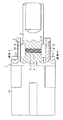
図1〜図3に示すこの発明の第1実施形態は、筒状のケーシング1に回転自在に軸部材2を挿入した回転ダンパに、一方向移動制限機構を設けたものである。ケーシング1のダンパ部1a内には、軸部材2との相対回転に制動力を付与するダンパ機構が組み込まれている。このダンパ機構は、例えば流体の粘性抵抗を利用したものなど、どのようなものでも良い。また、ダンパ機構を組み込んだ上記ダンパ部1aは必須ではなく、この発明の一方向移動制限機構とは直接関係がないので、ここではその説明は省略する。
第1実施形態の一方向制限機構は、図1において切り欠いた部分であり、ダンパ部1aから突出した筒部1bと軸部材2との相対回転時に、その回転方向に応じて移動制限をしたりしなかったりするものである。
In the first embodiment of the present invention shown in FIGS. 1 to 3, a one-way movement restriction mechanism is provided on a rotary damper in which a shaft member 2 is rotatably inserted into a cylindrical casing 1. A damper mechanism for applying a braking force to relative rotation with the shaft member 2 is incorporated in the damper portion 1 a of the casing 1. This damper mechanism may be any mechanism such as one utilizing a fluid viscous resistance. Further, the damper portion 1a incorporating the damper mechanism is not essential and is not directly related to the one-way movement restriction mechanism of the present invention, so that the description thereof is omitted here.
The unidirectional restriction mechanism of the first embodiment is a notched portion in FIG. 1, and restricts movement according to the rotation direction when the cylindrical part 1 b protruding from the damper part 1 a and the shaft member 2 are relatively rotated. Or not.

この第1実施形態では、この発明の第1相対移動部材である筒部1b内に、所定の間隔を保って第2相対移動部材である軸部材2を設けている。
そして、上記軸部材2の外周には、180°回転した位置に、軸方向溝からなる一対の保持部3を形成し、各保持部3にはそれぞれころ部材4を組み込み、ころ部材4を軸部材2の外周面より筒部1b側へ突出させて、ころ部材4によってこの発明の第2突出部を構成している。
なお、上記保持部3には、軸部材2の円周方向に隣り合う第1保持位置3aと第2保持位置3bとを備え、第1保持位置3aの深さを、第2保持位置3bよりも深くしている。
In the first embodiment, the shaft member 2 that is the second relative movement member is provided in the cylindrical portion 1b that is the first relative movement member of the present invention while maintaining a predetermined interval.
A pair of holding portions 3 each including an axial groove are formed on the outer periphery of the shaft member 2 at a position rotated by 180 °. Each of the holding portions 3 incorporates a roller member 4, and the roller member 4 is attached to the shaft. The roller member 4 is protruded from the outer peripheral surface of the member 2 toward the cylindrical portion 1b, and the second protruding portion of the present invention is configured.
The holding portion 3 includes a first holding position 3a and a second holding position 3b that are adjacent to each other in the circumferential direction of the shaft member 2, and the depth of the first holding position 3a is greater than that of the second holding position 3b. Is also deep.

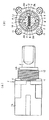
また、上記保持部3の第1保持位置3aの底面には軸部材2を貫通するばね保持穴5を形成し、このばね保持穴5内には、コイルばね6を挿入している。このコイルばね6は、その両端が上記保持部3内のころ部材4に接触して、ころ部材4を筒部1b側へ押圧するばね力を発揮する、この発明の第2押圧手段として機能する。   A spring holding hole 5 that penetrates the shaft member 2 is formed on the bottom surface of the first holding position 3 a of the holding portion 3, and a coil spring 6 is inserted into the spring holding hole 5. The coil spring 6 functions as a second pressing means of the present invention in which both ends thereof are in contact with the roller member 4 in the holding portion 3 and exert a spring force that presses the roller member 4 toward the cylindrical portion 1b. .

一方、筒部1bにおいて、上記軸部材2の保持部3に対応する部分には、180°回転した位置に軸方向に伸びる一対のスリット7,7を形成し、各スリット7には、直径方向に移動可能なころ部材8を収容し、このころ部材8がこの発明の第1突出部を構成している。
また、上記筒部1bの外周にはこの発明の第1押圧手段であるリングばね9を被せて、上記スリット7の位置において上記ころ部材8に対し、軸部材2側へ向かう弾性力を作用させるようにしている。なお、図2における符号10は、上記リングばね9の回転を規制するためのストッパ部である。
なお、上記第1押手段であるリングばね9のばね力を、第2押圧手段であるコイルばね6のばね力に比べて、圧倒的に大きく設定している。
また、図1中、符号11は、上記ダンパ部1aに筒部1bを固定するためのねじ部材である。
On the other hand, in the cylindrical portion 1b, a pair of slits 7 and 7 extending in the axial direction are formed at positions rotated by 180 ° in a portion corresponding to the holding portion 3 of the shaft member 2, and each slit 7 has a diameter direction. The roller member 8 which can move is accommodated, and this roller member 8 constitutes the first protrusion of the present invention.
Further, the outer periphery of the cylindrical portion 1b is covered with a ring spring 9, which is the first pressing means of the present invention, and an elastic force toward the shaft member 2 is applied to the roller member 8 at the position of the slit 7. I am doing so. In addition, the code | symbol 10 in FIG. 2 is a stopper part for controlling rotation of the said ring spring 9. In FIG.
Note that the spring force of the ring spring 9 as the first pressing means is set to be overwhelmingly larger than the spring force of the coil spring 6 as the second pressing means.
Moreover, in FIG. 1, the code | symbol 11 is a screw member for fixing the cylinder part 1b to the said damper part 1a.

次に、この第1実施形態の一方向移動制限機構の動作を説明する。
図2は、筒部1bに対して軸部材2を矢印A方向へ回転させたときの動作説明図であり、図3は、矢印Aと反対方向の矢印B方向へ軸部材2を回転させたときの動作説明図である。
Next, the operation of the unidirectional movement limiting mechanism of the first embodiment will be described.
FIG. 2 is an operation explanatory diagram when the shaft member 2 is rotated in the direction of arrow A with respect to the cylindrical portion 1b. FIG. 3 is a diagram of the shaft member 2 rotated in the direction of arrow B opposite to the arrow A. It is operation | movement explanatory drawing at the time.

図2(a)の状態から、軸部材2を矢印A方向に回転させるとき、保持部3の第2保持位置3bに位置したころ部材4は、上記コイルばね6の弱いばね力によって筒部1bの内周に軽く接触した状態を保って回転し、図2(b)のように軸部材側のころ部材4がケーシング側のころ部材8に接触する。上記ころ部材4がころ部材8に接触した状態で、軸部材2が矢印A方向へ回転すると、ころ部材4は、保持部3内で上記第2保持位置3bから円周方向に移動して第1保持位置3a側へ移る。   When the shaft member 2 is rotated in the direction of arrow A from the state of FIG. 2A, the roller member 4 positioned at the second holding position 3 b of the holding portion 3 is moved to the cylindrical portion 1 b by the weak spring force of the coil spring 6. The roller member 4 on the shaft member side contacts the roller member 8 on the casing side as shown in FIG. 2B. When the roller member 4 is in contact with the roller member 8 and the shaft member 2 rotates in the direction of arrow A, the roller member 4 moves in the holding portion 3 from the second holding position 3b in the circumferential direction. 1 Move to the holding position 3a side.

さらに、軸部材2に矢印A方向の回転力を作用させると、ころ部材4が第1保持位置3aでコイルばね6を撓ませて軸部材2の中心側へ移動して、ころ部材8と同一直径上に並ぶ(図2(c)参照)。
図2(c)から、軸部材2にさらに矢印A方向の回転力を作用させれば、図2(d)のように、ころ部材4がころ部材8を乗り越えて軸部材2が回転する。
このとき、ころ部材4は、上記第1位保持位置3aにおいて、コイルばね6に押されて筒部1bの内周に軽く押し当てられた状態を保っている。
Further, when a rotational force in the direction of arrow A is applied to the shaft member 2, the roller member 4 deflects the coil spring 6 at the first holding position 3 a and moves to the center side of the shaft member 2, and is the same as the roller member 8. It arranges on a diameter (refer FIG.2 (c)).
If a rotational force in the direction of arrow A is further applied to the shaft member 2 from FIG. 2C, the roller member 4 gets over the roller member 8 and the shaft member 2 rotates as shown in FIG. 2D.
At this time, the roller member 4 is kept pressed by the coil spring 6 and lightly pressed against the inner periphery of the cylindrical portion 1b at the first position holding position 3a.

なお、図2(c)の状態では、ころ部材4及びころ部材8には、コイルばね6及びリングばね9の弾性力が作用しているが、上記コイルばね6のばね力をリングばね9のばね力に比べて圧倒的に小さくしているので、ころ部材4がころ部材8を乗り越える際には、小さいばね力のコイルばね6を撓ませることで足りる。つまり、軸部材2を矢印A方向に回転させる場合には、大きな回転力を必要とせずに、スムーズに回転させることができる。   In the state of FIG. 2C, the elastic force of the coil spring 6 and the ring spring 9 is acting on the roller member 4 and the roller member 8, but the spring force of the coil spring 6 is applied to the ring spring 9. Since it is overwhelmingly smaller than the spring force, it is sufficient to bend the coil spring 6 having a small spring force when the roller member 4 gets over the roller member 8. That is, when the shaft member 2 is rotated in the direction of arrow A, it can be smoothly rotated without requiring a large rotational force.

一方、図2(d)の状態から軸部材2を矢印B方向に回転させるときの状態を図3に示している。
例えば、軸部材2を上記矢印A方向に回転させて上記ころ部材4がころ部材8を乗り越えた図2(d)の状態から、軸部材2を矢印B方向へ回転させると、ころ部材4は軸部材2と筒部1bとの間で転がって、図3(a)に示すように第1保持位置3aから第2保持位置3bに移動する。
この図3(a)の状態から軸部材2を矢印B方向へ回転させると、図3(b)に示すように軸部材2側のころ部材4がケーシング側のころ部材8に接触する。上記ころ部材4がころ部材8に接触した状態で、軸部材2が矢印B方向へ回転すると、第2保持位置3bに位置したころ部材4は軸部材2の中心側方向へ移動できない状態になっているため、図3(c)に示すように筒部1b側のころ部材8を外方へ押圧する。このころ部材4の押圧力が、ころ部材8を押圧する上記リングばね9の弾性力に打ち勝てば、ころ部材8が筒部1bの外方へ移動し、図3(c)のように、ころ部材4ところ部材8とが同一直径上に並んでから、ころ部材4がころ部材8を乗り越えて、図3(d)の状態まで回転する。
On the other hand, FIG. 3 shows a state where the shaft member 2 is rotated in the arrow B direction from the state of FIG.
For example, when the shaft member 2 is rotated in the direction of arrow A and the shaft member 2 is rotated in the direction of arrow B from the state of FIG. It rolls between the shaft member 2 and the cylindrical part 1b and moves from the first holding position 3a to the second holding position 3b as shown in FIG.
When the shaft member 2 is rotated in the arrow B direction from the state of FIG. 3A, the roller member 4 on the shaft member 2 side contacts the roller member 8 on the casing side as shown in FIG. 3B. When the shaft member 2 rotates in the arrow B direction while the roller member 4 is in contact with the roller member 8, the roller member 4 located at the second holding position 3b cannot move in the center side direction of the shaft member 2. Therefore, as shown in FIG. 3 (c), the roller member 8 on the cylindrical portion 1b side is pressed outward. When the pressing force of the roller member 4 overcomes the elastic force of the ring spring 9 that presses the roller member 8, the roller member 8 moves outward from the cylindrical portion 1b, and as shown in FIG. After the member 4 and the member 8 are aligned on the same diameter, the roller member 4 gets over the roller member 8 and rotates to the state shown in FIG.

このように軸部材2を矢印B方向へ回転するときには、図3(b)の状態からころ部材4がころ部材8を乗り越えて回転する過程で、上記リングばね9の大きな弾性力に抗する回転力を作用させる必要がある。
なお、ここでは上記図2(d)の状態から軸部材2を矢印B方向へ回転させたとき、ころ部材4が転がって第1保持位置3aから第2保持位置3bに移動する(図3(a)参照)場合を説明しているが、上記コイルばね6のばね力が非常に小さくて、ころ部材4と筒部1bとの間の摩擦力が小さい場合には、ころ部材4が転がらないで第1保持位置3aに留まることもある。
その場合であっても、軸部材2が矢印B方向に回転して、図3(b)に示すように、ころ部材4ところ部材8とが接触すれば、ころ部材4は第2保持位置3bに移動してからころ部材8を乗り越えることになる。
Thus, when the shaft member 2 is rotated in the direction of arrow B, the roller member 4 rotates over the roller member 8 from the state shown in FIG. 3B and rotates against the large elastic force of the ring spring 9. It is necessary to apply force.
Here, when the shaft member 2 is rotated in the arrow B direction from the state of FIG. 2D, the roller member 4 rolls and moves from the first holding position 3a to the second holding position 3b (FIG. 3 ( a) see) The case is explained, but when the spring force of the coil spring 6 is very small and the frictional force between the roller member 4 and the cylindrical portion 1b is small, the roller member 4 does not roll. In some cases, the first holding position 3a may remain.
Even in this case, if the shaft member 2 rotates in the direction of the arrow B and the roller member 4 and the member 8 come into contact with each other as shown in FIG. 3B, the roller member 4 is in the second holding position 3b. After moving to, the roller member 8 is overcome.

この第1実施形態では、軸部材2を矢印A方向へ回転させる際には、軸部材側のころ部材4がケーシング側のころ部材を乗り越える過程で、特に大きな回転力を必要とせず、スムーズな回転が可能であるが、矢印B方向へ回転させる際には、上記ころ部材4がころ部材8を乗り越える過程で大きな回転力を必要とする。
つまり、軸部材の回転方向によって、ころ部材を乗り越える際に必要な力が変わる。
In the first embodiment, when the shaft member 2 is rotated in the direction of arrow A, the roller member 4 on the shaft member side passes over the roller member on the casing side, and thus a particularly large rotational force is not required and smooth. Although rotation is possible, when the roller member 4 is rotated in the direction of arrow B, a large rotational force is required in the process in which the roller member 4 gets over the roller member 8.
That is, the force required to get over the roller member varies depending on the rotation direction of the shaft member.

例えば、上記軸部材2に開閉蓋を連結し、筒部1bを本体に連結した場合、矢印A方向の回転によって蓋を開くようにすれば、開く時には特に違和感なく、ころ部材4がころ部材8を乗り越えることができるが、蓋が閉じるB方向に軸部材2が回転する場合には、上記リングばね9の弾性力に打ち勝つ力を作用させなければならないので、上記ころ部材4がころ部材8を乗り越えて蓋が自重で閉まるようなことはない。
なお、上記矢印A方向がこの発明の一方の方向であり、矢印B方向がこの発明の他の方向である。
For example, when an opening / closing lid is connected to the shaft member 2 and the cylinder portion 1b is connected to the main body, if the lid is opened by rotation in the direction of the arrow A, the roller member 4 is not particularly uncomfortable when opening, and the roller member 4 becomes the roller member 8 However, when the shaft member 2 rotates in the B direction in which the lid closes, a force that overcomes the elastic force of the ring spring 9 must be applied. You won't get over the lid by its own weight.
The arrow A direction is one direction of the present invention, and the arrow B direction is the other direction of the present invention.

また、この第1実施形態では、第1、第2突出部をころ部材8,4で構成しているが、第1、第2突出部はころ部材に限らない。
第2突出部が、相対移動部材の移動方向に応じて、保持部内の第1保持位置あるいは第2保持位置に位置する構成であれば、どのような部材によって上記突出部を構成してもよい。
Moreover, in this 1st Embodiment, although the 1st, 2nd protrusion part is comprised by the roller members 8 and 4, a 1st, 2nd protrusion part is not restricted to a roller member.
As long as the second protrusion is configured to be positioned at the first holding position or the second holding position in the holding portion according to the moving direction of the relative movement member, the protrusion may be configured by any member. .

図4に示す第2実施形態は、筒部1bの外周に、上記リングばね9に替えてにコイルばね12を巻きつけた点が、上記第1実施形態と異なる一方向移動制限機構である。
上記第1実施形態と同じ構成要素には、図1,2と同じ符号を用い、個々の要素について説明は省略する。
この第2実施形態では、筒部1bに巻きつけたコイルばね12の締め付け力が、第1突出部であるころ部材8を軸部材2方向へ押圧する押圧手段のばね力として機能する。そして、このコイルばね12の締め付け方向のばね力を、第2押圧手段である軸部材側のコイルばね6のばね力に比べて十分に大きくしている。
The second embodiment shown in FIG. 4 is a unidirectional movement limiting mechanism that differs from the first embodiment in that a coil spring 12 is wound around the outer periphery of the cylindrical portion 1b instead of the ring spring 9.
The same reference numerals as those in FIGS. 1 and 2 are used for the same constituent elements as those in the first embodiment, and description of the individual elements is omitted.
In this 2nd Embodiment, the clamping force of the coil spring 12 wound around the cylinder part 1b functions as a spring force of the press means which presses the roller member 8 which is a 1st protrusion part to the shaft member 2 direction. The spring force in the tightening direction of the coil spring 12 is sufficiently larger than the spring force of the coil spring 6 on the shaft member side which is the second pressing means.

この第2実施形態においても、軸部材2を矢印A方向に回転させる方向が、この発明の一方の方向であり、このとき、ころ部材4が保持部3の第1保持位置3aに位置して、コイルばね6を軽く撓ませることによって筒部1b側のころ部材8を乗り越えて回転する(図2参照)。   Also in the second embodiment, the direction in which the shaft member 2 is rotated in the direction of arrow A is one direction of the present invention. At this time, the roller member 4 is positioned at the first holding position 3a of the holding portion 3. Then, the coil spring 6 is lightly bent to rotate over the roller member 8 on the cylindrical portion 1b side (see FIG. 2).

一方、軸部材2を矢印B方向に回転させる方向が、この発明の他の方向であり、保持部3の第2保持位置3bに位置したころ部材4が、ころ部材8を介してコイルばね12を押し広げなければ、ころ部材8を乗り越えることができず、移動が制限されることになる(図3参照)。
このように、第2実施形態においても、筒部1bと軸部材2との相対回転方向によって、その回転を制限したりしなかったりできる。
On the other hand, the direction in which the shaft member 2 is rotated in the direction of arrow B is the other direction of the present invention, and the roller member 4 positioned at the second holding position 3b of the holding portion 3 is rotated by the coil spring 12 via the roller member 8. If is not spread out, the roller member 8 cannot be overcome and the movement is restricted (see FIG. 3).
Thus, also in 2nd Embodiment, the rotation can be restrict | limited by the relative rotation direction of the cylinder part 1b and the shaft member 2. FIG.

図5に示す第3実施形態は、上記筒部1bの外周に設けたリングばね13を曲げて、筒部1bに形成したスリット7から突出する第1突出部13aを形成した点が、上記第1実施形態と異なるが、その他の構成は第1実施形態と同じである。第1実施形態と同じ構成要素には、第1実施形態と同じ符号を用いる。
この第3実施形態では、この発明の第1押圧手段であるリングばね13が、第1突出部13aと一体化している点が特徴であり、上記第1実施形態のように、第1押圧手段と別に第1突出部であるころ部材8を用いた場合と比べて、部品点数を少なくでき、組み付け工程も単純化できる。
この場合も、上記リングばね13のばね力を、第2押圧手段である上記リングばね6のばね力に比べて十分に大きくしている。
The third embodiment shown in FIG. 5 is that the ring spring 13 provided on the outer periphery of the cylindrical portion 1b is bent to form the first protruding portion 13a protruding from the slit 7 formed in the cylindrical portion 1b. Although different from the first embodiment, other configurations are the same as those of the first embodiment. The same reference numerals as those in the first embodiment are used for the same components as those in the first embodiment.
The third embodiment is characterized in that the ring spring 13 which is the first pressing means of the present invention is integrated with the first protruding portion 13a, and the first pressing means as in the first embodiment. In addition, the number of parts can be reduced and the assembly process can be simplified as compared with the case where the roller member 8 which is the first protrusion is used.
Also in this case, the spring force of the ring spring 13 is sufficiently larger than the spring force of the ring spring 6 as the second pressing means.

但し、一方向移動制限機構としての作用は、第1実施形態と同じである。
すなわち、軸部材2を矢印A方向に回転させる方向が、この発明の一方の方向であり、ころ部材4が突出部13aを軽く乗り越えて回転する(図2参照)。
一方、軸部材2を矢印B方向に回転させる方向が、この発明の他の方向であり、上記第2保持位置3bに位置するころ部材4は、上記リングばね13のばね力に抗して上記突出部13aを外方へ移動させなければ、突出部13aを乗り越えて回転することはできない(図3参照)。
このように、第3実施形態においても、筒部1bと軸部材2との相対回転方向によって、その回転を制限したりしなかったりできる。
However, the operation as the one-way movement restriction mechanism is the same as that of the first embodiment.
That is, the direction in which the shaft member 2 is rotated in the direction of arrow A is one direction of the present invention, and the roller member 4 rotates slightly over the protruding portion 13a (see FIG. 2).
On the other hand, the direction in which the shaft member 2 is rotated in the direction of arrow B is the other direction of the present invention, and the roller member 4 positioned at the second holding position 3b is against the spring force of the ring spring 13 described above. If the protrusion 13a is not moved outward, the protrusion 13a cannot be overcome and rotated (see FIG. 3).
Thus, also in 3rd Embodiment, the rotation can be restrict | limited by the relative rotation direction of the cylinder part 1b and the shaft member 2. FIG.

図6,7に示す第4実施形態は、軸部材2が第1相対移動部材であり、筒部1bが第2相対移動部材である一方向移動制限機構である。そして、第1実施形態と同様の機能を有する構成要素には、第1実施形態と同じ符号を用いている。
この第4実施形態では、軸部材2にばね保持穴14を形成し、第1押圧手段であるコイルばね15を組み込むとともに、その両端には保持溝16を形成して、そこに第1突出部であるころ部材8を設けている。
The fourth embodiment shown in FIGS. 6 and 7 is a one-way movement restriction mechanism in which the shaft member 2 is a first relative movement member and the cylindrical portion 1b is a second relative movement member. And the same code | symbol as 1st Embodiment is used for the component which has the function similar to 1st Embodiment.
In the fourth embodiment, a spring holding hole 14 is formed in the shaft member 2 and a coil spring 15 as a first pressing means is incorporated, and holding grooves 16 are formed at both ends thereof, and the first projecting portion is provided there. The roller member 8 is provided.

一方、筒部1bの180°回転した位置には、一対のばね保持穴5を形成し、このばね保持穴5内には第2押圧手段であるコイルばね6を設けている。なお、上記第2押圧手段であるコイルばね6のばね力を、上記第1押圧手段であるコイルばね15のばね力に比べて圧倒的に小さくしている。
また、筒部1bのばね保持穴5の開口には、第2突出部であるころ部材4を保持する保持部3を形成している。そして、この保持部3には筒部1bの内周面からの深さを深くして、ばね保持穴5と同一直径上に位置する第1保持位置3aと、この第1位保持位置3aと隣接し、筒部1bの内周面からの深さを浅くした第2保持位置3bとを備えている。
On the other hand, a pair of spring holding holes 5 is formed at a position rotated 180 ° of the cylindrical portion 1b, and a coil spring 6 as a second pressing means is provided in the spring holding hole 5. Note that the spring force of the coil spring 6 as the second pressing means is overwhelmingly smaller than the spring force of the coil spring 15 as the first pressing means.
Moreover, the holding part 3 holding the roller member 4 which is a 2nd protrusion part is formed in opening of the spring holding hole 5 of the cylinder part 1b. The holding portion 3 has a first holding position 3a positioned on the same diameter as the spring holding hole 5 by increasing the depth from the inner peripheral surface of the cylindrical portion 1b, and the first holding position 3a. 2nd holding position 3b which adjoined and made shallow the depth from the internal peripheral surface of the cylinder part 1b is provided.

この第4実施形態の一方向移動制限機構では、図6(a)の状態で、上記ころ部材4はコイルばね6に押されて第2保持位置3bに位置している。この図6(a)の状態から、軸部材2が矢印A方向へ回転して、図6(b)のように軸部材2側のころ部材8が筒部1b側のころ部材4を円周方向に押すと、ころ部材4が保持部3の第1保持位置3a側に移動する。さらに軸部材2に矢印A方向の回転力を作用させると、図6(c)に示すように筒部1b側のコイルばね6を撓ませてころ部材4が筒部1b内周面から外方へ移動する。これにより、第2突出部であるころ部材4が第1突出部であるころ部材8を乗り越えて、図6(d)の状態になる。この状態で、上記ころ部材4は再び上記コイルばね6に押されて第2保持位置3b側へ移動する。
上記図6(c)で撓むコイルばね6はばね力の小さいものであり、そのため軸部材2が筒部1bに対して矢印A方向に回転する相対回転には、ほとんど抵抗や違和感を与えない。
In the unidirectional movement limiting mechanism of the fourth embodiment, the roller member 4 is pushed by the coil spring 6 and is positioned at the second holding position 3b in the state of FIG. From the state of FIG. 6A, the shaft member 2 rotates in the direction of arrow A, and the roller member 8 on the shaft member 2 side rotates the roller member 4 on the cylindrical portion 1b side as shown in FIG. 6B. When pushed in the direction, the roller member 4 moves to the first holding position 3a side of the holding portion 3. Further, when a rotational force in the direction of arrow A is applied to the shaft member 2, the coil spring 6 on the cylindrical portion 1b side is bent as shown in FIG. 6C, so that the roller member 4 moves outward from the inner peripheral surface of the cylindrical portion 1b. Move to. Thereby, the roller member 4 which is a 2nd protrusion part gets over the roller member 8 which is a 1st protrusion part, and will be in the state of FIG.6 (d). In this state, the roller member 4 is again pushed by the coil spring 6 and moves to the second holding position 3b side.
The coil spring 6 bent in FIG. 6 (c) has a small spring force, so that the relative rotation in which the shaft member 2 rotates in the direction of the arrow A with respect to the cylindrical portion 1b hardly gives resistance or a sense of incongruity. .

一方、上記軸部材2が矢印B方向に回転する場合、上記図6の(d)と同様に、ころ部材4がコイルばね6に押されて第2保持位置3bに位置している図7(a)の状態から軸部材2が回転し、図7(b)の状態まで軸部材2が回転すると、ころ部材8がころ部材4に当接する。そして、図7(b)に示すように上記ころ部材8がころ部材4を円周方向に押すので、ころ部材4は保持部3内の第2保持位置3bを維持する。
この状態で、軸部材2にさらに矢印B方向の回転力を作用させると、ころ部材4は第2保持位置3bにあって筒部1bの外方へ移動できない状態になっているため、図7(c)に示すように、第2押圧手段であるコイルばね15が撓んでころ部材8が軸部材2の中心側に移動する。これにより、ころ部材4がころ部材8を乗り越えて、図7(d)まで回転することになる。
On the other hand, when the shaft member 2 rotates in the direction of arrow B, the roller member 4 is pushed by the coil spring 6 and is positioned at the second holding position 3b, as in FIG. When the shaft member 2 rotates from the state of a) and the shaft member 2 rotates to the state of FIG. 7B, the roller member 8 contacts the roller member 4. 7B, the roller member 8 pushes the roller member 4 in the circumferential direction, so that the roller member 4 maintains the second holding position 3b in the holding portion 3.
In this state, when a rotational force in the direction of arrow B is further applied to the shaft member 2, the roller member 4 is in the second holding position 3b and cannot move outward from the cylindrical portion 1b. As shown in (c), the coil spring 15 as the second pressing means is bent and the roller member 8 moves to the center side of the shaft member 2. As a result, the roller member 4 gets over the roller member 8 and rotates to FIG.

上記図7(c)で撓むコイルばね15は、第2押圧手段であるコイルばね6に比べてばね力が大きいものである。従って、このコイルばね15のばね力に抗して筒部1bと軸部材2とが相対回転するためには、大きな回転力を作用させる必要があり、上記ばね力が矢印B方向の不用意な回転を制限することになる。
このように、第4実施形態においても、筒部1bと軸部材2との相対回転方向によって、その回転を制限したりしなかったりできる。
The coil spring 15 that is bent in FIG. 7C has a larger spring force than the coil spring 6 that is the second pressing means. Therefore, in order for the cylindrical portion 1b and the shaft member 2 to rotate relative to the spring force of the coil spring 15, it is necessary to apply a large rotational force, and the spring force is inadvertent in the direction of arrow B. It will limit the rotation.
Thus, also in 4th Embodiment, the rotation can be restrict | limited by the relative rotation direction of the cylinder part 1b and the shaft member 2. FIG.

図8、9に示す第5実施形態は、軸部材2に第2押圧手段であるコイルばね6を設けていない点が、第1実施形態と異なる。その他の構成は、第1実施形態と同じであり、第1実施形態と同じ構成要素には、同じ符号を用いている。
この第5実施形態において、軸部材2が矢印A方向に回転する場合、すなわちこの発明の一方の方向に移動する場合の状態を、図8(a)、(b)、(c)、(d)に示し、矢印B方向に回転する場合、すなわちこの発明の他の方向に移動する場合を図9(a)、(b)、(c)、(d)に示している。
The fifth embodiment shown in FIGS. 8 and 9 is different from the first embodiment in that the shaft member 2 is not provided with the coil spring 6 as the second pressing means. Other configurations are the same as those of the first embodiment, and the same reference numerals are used for the same components as those of the first embodiment.
In the fifth embodiment, the state when the shaft member 2 rotates in the direction of the arrow A, that is, when it moves in one direction of the present invention is shown in FIGS. 8 (a), 8 (b), 8 (c), 8 (d). 9A and 9B show the case of rotating in the direction of the arrow B, that is, the case of moving in the other direction of the present invention.

図8(a)に示すように、第2突出部であるころ部材4が第2保持位置3bに位置している状態から、軸部材2を矢印A方向に回転させると、ころ部材4が軸部材2とともに移動し、第1突出部であるころ部材8に当接し、このころ部材8に押し付けられる力によって、図8(b)に示すようにころ部材4は保持部3内の第1保持位置3a側へ移動する。ころ部材4は第1保持位置3aに移動すると、軸部材2の外周面からの突出量が小さくなる。この状態でさらに矢印A方向の回転力を作用させると、図8(c)に示すように、リングばね9をわずかに撓ませて第2突出部であるころ部材4が第1突出部であるころ部材8を乗り越えて回転する。上記リングばね9のばね力は大きいが、わずかにしか撓まない場合には、わずかな弾性力しか作用しないので、図8(c)の状態でリングばね9を撓ませても、その弾性力による抵抗は小さく、軸部材2の回転は制限されない。   As shown in FIG. 8A, when the roller member 4 that is the second protrusion is located at the second holding position 3b and the shaft member 2 is rotated in the direction of the arrow A, the roller member 4 becomes the shaft. The roller member 4 moves together with the member 2, abuts against the roller member 8 that is the first protrusion, and is pressed against the roller member 8, so that the roller member 4 is held in the first holding portion 3 as shown in FIG. Move to position 3a. When the roller member 4 moves to the first holding position 3a, the amount of protrusion from the outer peripheral surface of the shaft member 2 decreases. When a rotational force in the direction of arrow A is further applied in this state, as shown in FIG. 8C, the ring spring 9 is slightly bent, and the roller member 4 as the second protrusion is the first protrusion. The roller member 8 gets over and rotates. Although the spring force of the ring spring 9 is large, if it bends only slightly, only a small elastic force acts. Therefore, even if the ring spring 9 is bent in the state of FIG. The resistance by is small, and the rotation of the shaft member 2 is not limited.

なお、上記図8(c)の状態からころ部材4がころ部材8を乗り越える際には、ころ部材8による円周方向の力が作用するので、ころ部材8を乗り終えた直後には、図8(d)に示すようにころ部材4が第1保持位置3aに位置している。ただし、その後、ころ部材4が第1保持位置3aに留まるか、第2保持位置3bに移動するかは、摺動面の摩擦や回転力の影響によって、何れの場合もある。   When the roller member 4 gets over the roller member 8 from the state shown in FIG. 8C, the circumferential force by the roller member 8 acts. As shown in FIG. 8D, the roller member 4 is located at the first holding position 3a. However, after that, whether the roller member 4 stays at the first holding position 3a or moves to the second holding position 3b may be either due to the friction of the sliding surface or the influence of the rotational force.

上記では、ころ部材4ところ部材8とが当接する以前の図8(a)の状態で、第2保持位置3bに位置しているころ部材4が、ころ部材8に押されることによって第1保持位置3aへ移動する場合を説明しているが、図8(a)と同様の回転状態において、特に力が作用していなければ、ころ部材4が第1保持位置3aに位置することもある。このように、ころ部材8に当接する以前からころ部材4が第1保持位置3aに位置している場合には、ころ部材8との当接後も第1保持位置3aを維持したまま、ころ部材4がころ部材8を乗り越えることになる。従ってこの場合も、ころ部材4はころ部材8を軽く乗り越えることができ、相対回転は制限されない。   In the above description, the roller member 4 positioned at the second holding position 3b is pressed by the roller member 8 in the state shown in FIG. Although the case of moving to the position 3a has been described, the roller member 4 may be positioned at the first holding position 3a in the same rotational state as in FIG. As described above, when the roller member 4 has been positioned at the first holding position 3a before contacting the roller member 8, the roller is kept in the first holding position 3a after the contact with the roller member 8. The member 4 gets over the roller member 8. Therefore, also in this case, the roller member 4 can easily get over the roller member 8, and the relative rotation is not limited.

また、軸部材2を矢印B方向に回転させる場合について図9を用いて説明する。
図9(a)に示すように、ころ部材4が第1保持位置3aに位置した状態から軸部材2を矢印B方向へ回転させるところ部材4が矢印B方向に回転する軸部材2とともに移動し、図9(b)のように、ころ部材4がころ部材8に当接する。さらに矢印B方向の回転力を軸部材2に作用させると、ころ部材4がころ部材8に押し付けられ、ころ部材8による円周方向の力によって、図9(c)に示すようにころ部材4は保持部3内の第2保持位置3b側へ移動し、軸部材2の外周面からの突出量は、上記図9(b)と比べて大きくなる。
Moreover, the case where the shaft member 2 is rotated in the arrow B direction will be described with reference to FIG.
As shown in FIG. 9A, when the roller member 4 is in the first holding position 3a and the shaft member 2 is rotated in the arrow B direction, the member 4 moves together with the shaft member 2 rotating in the arrow B direction. 9B, the roller member 4 comes into contact with the roller member 8. As shown in FIG. Further, when a rotational force in the direction of arrow B is applied to the shaft member 2, the roller member 4 is pressed against the roller member 8, and the roller member 4 is pressed by the circumferential force by the roller member 8 as shown in FIG. Moves to the second holding position 3b side in the holding portion 3, and the protruding amount from the outer peripheral surface of the shaft member 2 becomes larger than that in FIG. 9B.

この状態でさらに矢印B方向の回転力を作用させると、図9(d)に示すように、リングばね9を大きく撓ませて上記ころ部材8が筒部1bの外方へ移動するので、第2突出部であるころ部材4が第1突出部であるころ部材8を乗り越えて回転し、図8(a)や図9(a)の状態になる。図9(d)のようにリングばね9が大きく撓む場合には、大きなばね力が上記ころ部材8、4を介して軸部材2を押圧する弾性力として作用するので、軸部材2の回転が制限されることになる。   If a rotational force in the direction of arrow B is further applied in this state, as shown in FIG. 9 (d), the ring spring 9 is greatly deflected and the roller member 8 moves outward from the cylindrical portion 1b. The roller member 4 that is the two projecting portions rotates over the roller member 8 that is the first projecting portion, and the state shown in FIGS. 8A and 9A is obtained. When the ring spring 9 bends greatly as shown in FIG. 9D, a large spring force acts as an elastic force that presses the shaft member 2 via the roller members 8 and 4. Will be limited.

上記では、ころ部材4ところ部材8とが当接する以前の図9(a)の状態で、第1保持位置3aに位置しているころ部材4が、ころ部材8に押されることによって第2保持位置3bへ移動する場合を説明しているが、図9(a)と同様の回転状態において、ころ部材4に特に力が作用していなければ、ころ部材4が第2保持位置3bに位置することもある。このように、ころ部材8に当接する以前からころ部材4が第2保持位置3bに位置している場合には、ころ部材8との当接後も第2保持位置3bを維持したまま、ころ部材4がころ部材8を乗り越えることになる。従ってこの場合も、ころ部材4はころ部材8を乗り越える際には、大きな力が必要であり、相対回転は制限される。   In the above description, the roller member 4 positioned at the first holding position 3a is pressed by the roller member 8 in the state shown in FIG. Although the case of moving to the position 3b is described, in the same rotation state as in FIG. 9A, if no force is applied to the roller member 4, the roller member 4 is positioned at the second holding position 3b. Sometimes. In this way, when the roller member 4 has been positioned at the second holding position 3b before contacting the roller member 8, the roller holding state 3b is maintained even after the contact with the roller member 8, and the roller The member 4 gets over the roller member 8. Therefore, also in this case, when the roller member 4 gets over the roller member 8, a large force is required, and the relative rotation is limited.

この第5実施形態では、第1、第2突出部に対する押圧手段が第1押圧手段であるリングばね9のみであるが、筒部1bと軸部材2との相対回転方向に応じて、撓み量が異なるため、作用する弾性力の大きさが異なり、回転方向によってその移動を制限したりしなかったりすることができる。   In the fifth embodiment, the pressing means for the first and second projecting portions is only the ring spring 9 that is the first pressing means, but the amount of deflection depends on the relative rotational direction of the cylindrical portion 1b and the shaft member 2. Therefore, the magnitude of the acting elastic force is different, and the movement can be restricted or not depending on the rotation direction.

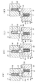
図10、11に示す第6実施形態は、第2相対移動部材である筒部材17と相対回転する第1相対移動部材である回転体18との間の回転を、その回転方向に応じて制限する一方向移動制限機構を、上記筒部材17の内底面に設けたものである。そして、第2相対移動部材である上記筒部材17には、第1実施形態の軸部材2に設けたものと同様のコイルばね6、ころ部材4及び保持部3を設け、第1相対移動部材である回転体18の底面には、上記第4実施形態の筒部1bに設けたコイルばね15、ころ部材8及び保持溝16を設けている。   In the sixth embodiment shown in FIGS. 10 and 11, the rotation between the cylindrical member 17 that is the second relative movement member and the rotating body 18 that is the first relative movement member that rotates relative to each other is limited according to the rotation direction. A one-way movement restriction mechanism is provided on the inner bottom surface of the cylindrical member 17. And the said cylindrical member 17 which is a 2nd relative displacement member is provided with the same coil spring 6, the roller member 4, and the holding | maintenance part 3 as what was provided in the shaft member 2 of 1st Embodiment, and a 1st relative displacement member On the bottom surface of the rotating body 18, the coil spring 15, the roller member 8, and the holding groove 16 provided in the cylindrical portion 1 b of the fourth embodiment are provided.

なお、この第6実施形態において、上記第1実施形態及び第4実施形態と同じ構成要素には、第1、第4実施形態と同じ符号を用いている。そして、上記コイルばね6のばね力を、上記コイルばね15のばね力よりも小さくしている点も、上記他の実施形態と同じである。
また、図10(a)、図11(a)は、筒部材17から回転体18を取り除いた状態の平面図であり、図10(b)、図11(b)は、筒部材17に回転体18を組み付けた状態での軸方向断面図である。
In the sixth embodiment, the same reference numerals as those in the first and fourth embodiments are used for the same constituent elements as those in the first and fourth embodiments. And the point which made the spring force of the said coil spring 6 smaller than the spring force of the said coil spring 15 is the same as said other embodiment.
FIGS. 10A and 11A are plan views in a state where the rotating body 18 is removed from the cylindrical member 17, and FIGS. 10B and 11B are rotated by the cylindrical member 17. It is an axial sectional view in the state where body 18 was assembled.

さらに、上記筒部材17の内底面に設けたころ部材4の保持部3は、中心に向かう線状溝からなり、隣り合う第1保持位置3aと第2保持位置3bとを備えている。
上記第1保持位置3aは、第2保持位置よりも、筒部材17の内底面からの深さを深くした溝であり、その底面に形成したばね保持穴5にはコイルばね6を組み込み、上記ころ部材4が上記回転体18の底面に軽く接触する程度の弾性力を発揮している。
また、上記回転体18の底面には、上記保持部3と対応する位置に保持溝16を形成し、この保持溝16でころ部材8を保持するとともに、軸方向にばね保持穴14を形成し、このばね保持穴14にコイルばね15を収容している。
Further, the holding portion 3 of the roller member 4 provided on the inner bottom surface of the cylindrical member 17 is formed of a linear groove toward the center, and includes a first holding position 3a and a second holding position 3b that are adjacent to each other.
The first holding position 3a is a groove whose depth from the inner bottom surface of the cylindrical member 17 is deeper than that of the second holding position, and a coil spring 6 is incorporated in the spring holding hole 5 formed on the bottom surface. The roller member 4 exhibits an elastic force such that the roller member 4 is in light contact with the bottom surface of the rotating body 18.
A holding groove 16 is formed on the bottom surface of the rotating body 18 at a position corresponding to the holding portion 3, the roller member 8 is held by the holding groove 16, and a spring holding hole 14 is formed in the axial direction. The coil spring 15 is accommodated in the spring holding hole 14.

この第6実施形態において、回転体18を図10(a)の矢印A方向に回転させると、二点鎖線で示すころ部材8が矢印Aのように移動し、ころ部材4を保持部3の第1保持位置3aに位置させる。この状態で筒部材17側のころ部材4がころ部材8を乗り越えるときには、図10(b)に示すとおり、ばね力の弱いほうのコイルばね6を撓ませることになる。   In the sixth embodiment, when the rotating body 18 is rotated in the direction of arrow A in FIG. 10A, the roller member 8 indicated by a two-dot chain line moves as indicated by arrow A, and the roller member 4 is moved to the holding portion 3. It is located at the first holding position 3a. In this state, when the roller member 4 on the cylindrical member 17 side gets over the roller member 8, the coil spring 6 having a weak spring force is bent as shown in FIG.

一方、回転体18を図11の矢印B方向に回転させる場合、図11(a)の状態では、筒部材17側のころ部材4はコイルばね6に押されて保持部3の第2保持位置3bに位置している。この状態で回転体18を矢印B方向へ回転させると、二点鎖線で示すころ部材8が矢印Bのように移動し、ころ部材4を保持部3の第2保持位置3bに位置させる。この状態で筒部材17側のころ部材4がころ部材8を乗り越えるときには、図11(b)に示すとおり、ばね力の大きい方のコイルばね15を撓ませることになる。つまり、コイルばね15の弾性力に打ち勝つ回転力を作用させなければ、上記筒部材17と回転体18との相対回転は制限されることになる。
このように、第6実施形態においても、筒部材17と回転体18との相対回転方向によって、その回転を制限したりしなかったりできる。
On the other hand, when the rotating body 18 is rotated in the direction of arrow B in FIG. 11, in the state of FIG. 11A, the roller member 4 on the cylindrical member 17 side is pushed by the coil spring 6 and the second holding position of the holding portion 3. Located at 3b. When the rotating body 18 is rotated in the arrow B direction in this state, the roller member 8 indicated by a two-dot chain line moves as indicated by the arrow B, and the roller member 4 is positioned at the second holding position 3b of the holding portion 3. In this state, when the roller member 4 on the cylindrical member 17 side gets over the roller member 8, as shown in FIG. 11B, the coil spring 15 having the larger spring force is bent. That is, unless a rotational force that overcomes the elastic force of the coil spring 15 is applied, the relative rotation between the cylindrical member 17 and the rotating body 18 is limited.
Thus, also in 6th Embodiment, the rotation can be restrict | limited by the relative rotation direction of the cylindrical member 17 and the rotary body 18. FIG.

図12、13に示す第7実施形態は、第1相対移動部材である第1スライド部材19と、この第1スライド部材19に対して直線的にスライド可能な第2相対移動部材である第2スライド部材20との間の相対移動を、その移動方向に応じて制限する一方向移動制限機構である。
そして、上記第1スライド部材19における第2スライド部材20との対向面には、図10,11に示す第6実施形態の回転部材18と同様に、第1押圧手段であるコイルばね15を収容するばね保持穴14、第1突出部であるころ部材8を保持する保持溝16を設けている。
The seventh embodiment shown in FIGS. 12 and 13 is a first slide member 19 that is a first relative movement member, and a second relative movement member that is linearly slidable with respect to the first slide member 19. It is a one-way movement restriction mechanism that restricts relative movement with the slide member 20 according to the movement direction.
And the coil spring 15 which is a 1st press means is accommodated in the surface facing the 2nd slide member 20 in the said 1st slide member 19 similarly to the rotating member 18 of 6th Embodiment shown to FIG. A spring holding hole 14 for holding and a holding groove 16 for holding the roller member 8 as the first projecting portion are provided.

また、第2スライド部材20における第1スライド部材19との対向面には、上記第6実施形態の筒部材17と同様に、第2押圧手段であるコイルばね6を収容するばね保持穴5、第2突出部であるころ部材4を保持する保持部3を設けている。
なお、この第7実施形態において、上記第6実施形態と同様の構成要素には、第6実施形態と同じ符号を用いている。
Further, on the surface of the second slide member 20 that faces the first slide member 19, the spring holding hole 5 that houses the coil spring 6 that is the second pressing means, similarly to the cylindrical member 17 of the sixth embodiment, A holding portion 3 that holds the roller member 4 that is the second protruding portion is provided.
In the seventh embodiment, the same reference numerals as those in the sixth embodiment are used for the same constituent elements as those in the sixth embodiment.

この第7実施形態において、第2スライド部材20を図12(a)の状態から矢印A方向へ移動させると、図12(b)でころ部材4がころ部材8と接触してころ部材4がころ部材8を乗り越えて図12(d)の状態になるまでの過程で、図12(c)に示すとおり、ころ部材4が第1保持位置3aに位置して、コイルばね15よりもばね力が小さいコイルばね6を撓ませてころ部材8を乗り越えることになる。   In the seventh embodiment, when the second slide member 20 is moved from the state of FIG. 12A in the direction of arrow A, the roller member 4 comes into contact with the roller member 8 in FIG. In the process from getting over the roller member 8 to the state shown in FIG. 12D, the roller member 4 is positioned at the first holding position 3a as shown in FIG. Is bent over the roller member 8 by bending the small coil spring 6.

一方、第2スライド部材20を図13の矢印B方向に移動させる場合には、上記ころ部材8に押されたころ部材4が、図13(b)、(c)に示すように第2保持位置3bに位置したままころ部材8を乗り越えることになる。図13(c)に示すように、上記ころ部材4がころ部材8を乗り越えるときには、第1スライド部材19側のコイルばね15を撓ませている。このコイルばね15は、ばね力の大きなばねであり、それを撓ませるためには大きな外力が必要である。
つまり、第2スライド部材20を矢印B方向へ移動させて、ころ部材8を乗り越えるためには、大きな力が必要となり、この方向の相対移動は制限される。
このように、第7実施形態においても、第1スライド部材19と第2スライド部材20の相対移動方向に応じて、その移動を制限したりしなかったりできる。
On the other hand, when the second slide member 20 is moved in the direction of arrow B in FIG. 13, the roller member 4 pushed by the roller member 8 is held in the second position as shown in FIGS. 13 (b) and 13 (c). The roller member 8 is moved over while remaining in the position 3b. As shown in FIG. 13C, when the roller member 4 gets over the roller member 8, the coil spring 15 on the first slide member 19 side is bent. The coil spring 15 is a spring having a large spring force, and a large external force is required to bend it.
That is, in order to move the second slide member 20 in the arrow B direction and get over the roller member 8, a large force is required, and the relative movement in this direction is limited.
Thus, also in the seventh embodiment, the movement can be restricted or not depending on the relative movement direction of the first slide member 19 and the second slide member 20.

この第7実施形態のように、直線運動する相対移動部材間の移動を制限する機構は、引き戸などに用いることができる。例えば、制限なく、容易に開けることができる引き戸が不用意に閉まることがないようにしたり、反対に容易に閉めることができる引き戸が簡単に開かないようにしたりするためにこの第7実施形態の一方向相対移動制限機構を利用できる。
また、第1、第2スライド部材19,20の移動方向は水平方向に限らず、上下方向などいずれでもかまわない。
As in the seventh embodiment, a mechanism that restricts movement between relative moving members that linearly move can be used for a sliding door or the like. For example, in order to prevent a sliding door that can be easily opened without restriction from being inadvertently closed, or to prevent a sliding door that can be easily closed from being opened easily, A one-way relative movement limiting mechanism can be used.
Further, the moving direction of the first and second slide members 19 and 20 is not limited to the horizontal direction, and may be any direction such as the vertical direction.

図14に示す第8実施形態は、第2相対移動部材である軸部材2の外周上で、90°ずつ回転させた4箇所に、第2突出部であるころ部材4を設けた以外は、上記第1実施形態と同じである。そこで、この第8実施形態でも、第1実施形態と同様の機能を有する構成要素には第1実施形態と同じ符号を用いている。
この第8実施形態も、軸部材2を矢印A方向に回転させたときには、ころ部材4が保持部3の第1保持位置3aに位置し、ばね力が小さい第2押圧手段であるコイルばね6を撓ませてころ部材8を乗り越えることができる。そのため、軸部材2が矢印A方向に回転するときには制限は受けない。この動作は、図2に示す第2実施形態と同じである。
In the eighth embodiment shown in FIG. 14, except that the roller member 4 as the second protruding portion is provided at four positions rotated by 90 ° on the outer periphery of the shaft member 2 as the second relative movement member. The same as in the first embodiment. Therefore, in the eighth embodiment as well, the same reference numerals as those in the first embodiment are used for components having the same functions as in the first embodiment.
Also in the eighth embodiment, when the shaft member 2 is rotated in the direction of the arrow A, the roller member 4 is positioned at the first holding position 3a of the holding portion 3, and the coil spring 6 is a second pressing means having a small spring force. And the roller member 8 can be overcome. Therefore, no limitation is imposed when the shaft member 2 rotates in the direction of arrow A. This operation is the same as that of the second embodiment shown in FIG.

反対に、軸部材2が矢印B方向に回転する場合には、図3に示す第1実施形態と同様に、上記ころ部材4が保持部3の第2保持位置3bに位置するため、ころ部材4がころ部材8を乗り越える際にコイルばね6が撓まない。従って、ころ部材4がころ部材8を乗り越えて相対回転するためにはばね力を大きくしたリングばね9を撓ませる必要があり、回転が制限されることになる。
このように、第8実施形態においても、筒部1bと軸部材2との相対回転方向によって、その回転を制限したりしなかったりできる。
On the contrary, when the shaft member 2 rotates in the direction of arrow B, the roller member 4 is located at the second holding position 3b of the holding portion 3 as in the first embodiment shown in FIG. When 4 passes over the roller member 8, the coil spring 6 does not bend. Therefore, in order for the roller member 4 to get over the roller member 8 and relatively rotate, it is necessary to bend the ring spring 9 having a large spring force, which limits the rotation.
Thus, also in 8th Embodiment, the rotation can be restrict | limited by the relative rotation direction of the cylinder part 1b and the shaft member 2. FIG.

但し、この第8実施形態では上記ころ部材4を90°回転させた位置に設けるとともに、上記ころ部材8を180°回転した位置に設けているため、上記回転軸2が90°回転するごとにころ部材4がころ部材8を乗り越えることになる。従って、軸部材2を矢印B方向に回転させる際には、90°回転するごとにその回転を制限することができる。
なお、この実施形態では、ころ部材4を4個用いることで、相対回転を制限するタイミングを4回にしているが、上記ころ部材4の数は4個に限らない。また、上記ころ部材8の配置や数を変えることによっても、相対回転を制限するタイミングを増やしたり、減らしたりすることができる。
However, in the eighth embodiment, the roller member 4 is provided at a position rotated by 90 °, and the roller member 8 is provided at a position rotated by 180 °. Therefore, every time the rotary shaft 2 rotates by 90 °. The roller member 4 gets over the roller member 8. Therefore, when the shaft member 2 is rotated in the direction of arrow B, the rotation can be limited every time the shaft member 2 is rotated by 90 °.
In this embodiment, four roller members 4 are used to limit the relative rotation to four times. However, the number of the roller members 4 is not limited to four. Also, the timing for limiting the relative rotation can be increased or decreased by changing the arrangement or number of the roller members 8.

図15に示す第9実施形態は、第1相対回転部材である筒部1bに第1突部となるころ部材8を4箇所に設けた以外は、上記第1実施形態と同じである。そこで、この第9実施形態でも、第1実施形態と同様の機能を有する構成要素には第1実施形態と同じ符号を用いている。
この第9実施形態においても、軸部材2を矢印A方向に回転させたときには、上記図2に示す第1実施形態と同様に、ころ部材4が保持部3の第1保持位置3aに位置して、コイルばね6を撓ませてころ部材8を乗り越えることができる。そのため、この矢印A方向の回転には制限がなく、スムーズな回転が可能である。
The ninth embodiment shown in FIG. 15 is the same as the first embodiment except that the cylindrical member 1b, which is a first relative rotation member, is provided with four roller members 8 serving as first protrusions. Therefore, in the ninth embodiment, the same reference numerals as those in the first embodiment are used for components having the same functions as those in the first embodiment.
Also in the ninth embodiment, when the shaft member 2 is rotated in the direction of arrow A, the roller member 4 is positioned at the first holding position 3a of the holding portion 3 as in the first embodiment shown in FIG. Thus, the coil spring 6 can be bent to get over the roller member 8. Therefore, the rotation in the direction of arrow A is not limited, and smooth rotation is possible.

一方、上記軸部材2を矢印B方向に回転させたときには、上記図3に示す第1実施形態と同様に、ころ部材4は保持部3の第2保持位置3bに位置するので、コイルばね6でなく、ばね力を大きくしたリングばね9を撓ませてころ部材8を乗り越えなければならない。そのため、軸部材2が矢印B方向に回転するときには、上記ころ部材4がころ部材8を乗り越える際に、上記リングばね9の大きなばね力に打ち勝つ力を作用させなければならず、その回転が制限されることになる。
この第9実施形態は、第1突出部であるころ部材8の数を多くして、ころ部材4がそれを乗り越えるタイミング、すなわち矢印B方向の回転を制限するタイミングを多くしているが、この数は特に限定されない。
On the other hand, when the shaft member 2 is rotated in the direction of the arrow B, the roller member 4 is located at the second holding position 3b of the holding portion 3 as in the first embodiment shown in FIG. Instead, the ring spring 9 with increased spring force must be bent to overcome the roller member 8. Therefore, when the shaft member 2 rotates in the direction of arrow B, when the roller member 4 gets over the roller member 8, a force that overcomes the large spring force of the ring spring 9 must be applied, and the rotation is limited. Will be.
In the ninth embodiment, the number of the roller members 8 that are the first protrusions is increased, and the timing at which the roller member 4 gets over it, that is, the timing for limiting the rotation in the direction of the arrow B is increased. The number is not particularly limited.

そして、第1突出部あるいは第2突出部の何れの数や配置は上記実施形態に限定されないが、その数と配置とによって、相対移動を制限するタイミングを設定することができる。
なお、上記実施形態では、第1相対移動部材に対して第2相対移動部材が移動する場合を例に説明したが、この発明の一方向移動制限機構は、相対移動する第1、第2相対移動部材間に設け、その移動方向が一方のときには、制限がなく、他の方向のときにはその移動が制限されるというものであって、第1、第2相対移動部材はどちらの部材が移動してもよいし、両部材が同時に移動してもかまわない。
The number and arrangement of the first protrusions and the second protrusions are not limited to the above embodiment, but the timing for limiting the relative movement can be set by the number and arrangement.
In the above embodiment, the case where the second relative movement member moves relative to the first relative movement member has been described as an example. However, the unidirectional movement restriction mechanism of the present invention has the first and second relative movements. It is provided between the moving members, and there is no restriction when the moving direction is one, and the movement is restricted when the moving direction is the other, and either of the first and second relative moving members moves. Alternatively, both members may move simultaneously.

この発明は、開閉蓋が開いて起立状態を保つことができるようにしたり、開いた戸が不用意に閉じたり、閉じた戸が不用意に開いたりしないようにしたい場合に適用できる。   The present invention can be applied to a case where the open / close lid can be opened to maintain an upright state, or the opened door is not carelessly closed or the closed door is not carelessly opened.

1b 筒部
2 軸部材
3 保持部
3a 第1保持位置
3b 第2保持位置
4 (第2突出部である)ころ部材
6 (第2押圧手段である)コイルばね
8 (第1突出部である)ころ部材
9 (第1押圧手段である)リングばね
12 (第1押圧手段である)コイルばね
13 (第1押圧手段である)リングばね
13a (第1)突出部
15 (第1押圧手段である)コイルばね
17 (第2相対移動部材である)筒部材
18 (第1相対移動部材である)回転体
19 (第1相対移動部材である)第1スライド部材
20 (第2相対移動部材である)第2スライド部材
1b Tube part 2 Shaft member 3 Holding part 3a First holding position 3b Second holding position 4 Roller member 6 (second projecting part) Coil spring 8 (First projecting part) Roller member 9 (first pressing means) ring spring 12 (first pressing means) coil spring 13 (first pressing means) ring spring 13a (first) protrusion 15 (first pressing means) ) Coil spring 17 (second relative movement member) cylindrical member 18 (first relative movement member) rotator 19 (first relative movement member) first slide member 20 (second relative movement member) ) Second slide member

Claims (4)

第1相対移動部材と、この第1相対移動部材と相対移動する第2相対移動部材と、第1、第2相対移動部材には互いに対向する面に設けた第1、第2突出部と、上記第1相対移動部材あるいは第2相対移動部材のいずれか一方または双方に備え、上記第1突出部あるいは第2突出部を対向面側へ押圧する弾性力を作用させる押圧手段と、上記第2相対移動部材に設け、移動方向に隣接する第1保持位置と第2保持位置を設けるとともに上記第2突出部を上記第1、第2保持位置の範囲内で移動可能に保持する保持部とを備え、上記第1相対移動部材を第2相対移動部材に対して一方の方向に相対移動させる移動力を付与したとき、上記第2突出部が上記第1保持位置に位置しながら上記押圧手段の弾性力に抗して第1突出部を乗り越え、上記第1相対移動部材を第2相対移動部材に対して他の方向に相対移動させる移動力を付与したとき、上記第2突出部が上記第2保持位置に位置しながら上記押圧手段の弾性力に抗して第1突出部を乗り越え、上記第1相対移動部材が上記一方の方向に相対移動して上記第2突出部が第1突出部を乗り越える際に作用する弾性力よりも、上記第1相対移動部材が上記他方の方向に相対移動して上記第2突出部が第1突出部を乗り越える際に作用する弾性力の方が大きくなる構成にした一方向移動制限機構。   A first relative movement member, a second relative movement member that moves relative to the first relative movement member, first and second protrusions provided on surfaces facing each other on the first and second relative movement members, A pressing means provided on either one or both of the first relative moving member and the second relative moving member, for applying an elastic force for pressing the first projecting portion or the second projecting portion toward the opposing surface; and the second A first holding position and a second holding position which are provided on the relative movement member and are adjacent to each other in the moving direction, and a holding portion which holds the second projecting portion movably within the range of the first and second holding positions; And when the moving force for moving the first relative movement member relative to the second relative movement member in one direction is applied, the second protrusion is positioned at the first holding position while the pressing means Overcoming the first protrusion against the elastic force, When a moving force that moves the first relative moving member relative to the second relative moving member in the other direction is applied, the second protruding portion is positioned at the second holding position and resists the elastic force of the pressing means. Over the first protrusion, and the first relative movement member moves relatively in the one direction, and the first relative movement is greater than the elastic force acting when the second protrusion moves over the first protrusion. A one-way movement limiting mechanism configured such that an elastic force acting when the moving member relatively moves in the other direction and the second protruding portion gets over the first protruding portion is increased. 上記押圧手段は、少なくとも、第1突出部に弾性力を作用させる第1押圧手段からなる請求項1に記載の一方向移動制限機構。   The one-way movement limiting mechanism according to claim 1, wherein the pressing unit includes at least a first pressing unit that applies an elastic force to the first protrusion. 上記押圧手段は、上記第1押圧手段と、第2相対移動部材に設けるとともに第1押圧手段よりもばね力を小さくした第2押圧手段とからなり、この第2押圧手段は、第2突出部が第1保持位置にあるとき、第2突出部に対してばね力を作用させる構成にした請求項1または2に記載の一方向移動制限機構。   The pressing means includes the first pressing means and a second pressing means provided on the second relative movement member and having a spring force smaller than that of the first pressing means. The second pressing means includes a second protrusion. The one-way movement restriction mechanism according to claim 1 or 2, wherein a spring force is applied to the second protrusion when the is in the first holding position. 上記第1突出部を第1押圧手段と一体化した請求項2または3に記載の一方向移動制限機構。   The unidirectional movement restriction mechanism according to claim 2 or 3, wherein the first protrusion is integrated with the first pressing means.
JP2010265656A 2010-11-29 2010-11-29 Mechanism for restricting movement in one direction Withdrawn JP2012117563A (en)

Priority Applications (2)

Application Number Priority Date Filing Date Title
JP2010265656A JP2012117563A (en) 2010-11-29 2010-11-29 Mechanism for restricting movement in one direction
CN2011103865743A CN102562780A (en) 2010-11-29 2011-11-29 Unidirectional-motion limiting mechanism

Applications Claiming Priority (1)

Application Number Priority Date Filing Date Title
JP2010265656A JP2012117563A (en) 2010-11-29 2010-11-29 Mechanism for restricting movement in one direction

Publications (1)

Publication Number Publication Date
JP2012117563A true JP2012117563A (en) 2012-06-21

Family

ID=46409062

Family Applications (1)

Application Number Title Priority Date Filing Date
JP2010265656A Withdrawn JP2012117563A (en) 2010-11-29 2010-11-29 Mechanism for restricting movement in one direction

Country Status (2)

Country Link
JP (1) JP2012117563A (en)
CN (1) CN102562780A (en)

Cited By (1)

* Cited by examiner, † Cited by third party
Publication number Priority date Publication date Assignee Title
WO2017094685A1 (en) * 2015-12-03 2017-06-08 立川ブラインド工業株式会社 Clutch device and shielding device

Families Citing this family (1)

* Cited by examiner, † Cited by third party
Publication number Priority date Publication date Assignee Title
CN110753802B (en) * 2017-07-13 2021-05-11 拓基股份有限公司 Rotary damper with torque adjusting function

Cited By (3)

* Cited by examiner, † Cited by third party
Publication number Priority date Publication date Assignee Title
WO2017094685A1 (en) * 2015-12-03 2017-06-08 立川ブラインド工業株式会社 Clutch device and shielding device
JPWO2017094685A1 (en) * 2015-12-03 2018-10-04 立川ブラインド工業株式会社 Clutch device and shielding device
JP7090422B2 (en) 2015-12-03 2022-06-24 立川ブラインド工業株式会社 Clutch device and cloaking device

Also Published As

Publication number Publication date
CN102562780A (en) 2012-07-11

Similar Documents

Publication Publication Date Title
JP4048452B2 (en) Shock absorber
KR100561077B1 (en) hinge
CA2843834C (en) Damper
JP2000170813A (en) Rotary damper
EP2706256A2 (en) Rotary type damper
TW201009212A (en) Cylinder device, spring damper, and door closer using it
JPWO2008001951A1 (en) HINGE DEVICE AND ELECTRONIC DEVICE USING HINGE DEVICE
KR100625929B1 (en) Damper
JP5752528B2 (en) Rotating damper
JP2012117563A (en) Mechanism for restricting movement in one direction
WO2014091860A1 (en) Stay
KR200275886Y1 (en) Friction hinge device
JPWO2012133388A1 (en) Rotating damper
JP6497771B2 (en) Tilt hinge and electronic device
JP4281069B2 (en) Two-way clutch
KR20160046692A (en) Apparatus for rotating door
JP5507008B2 (en) Hinge mechanism and in-vehicle display device
KR101253832B1 (en) Device for opening and closing of electronic apparatus and electronic apparatus
JP3729551B2 (en) High torque damper
JP2015017689A5 (en) Hinge mechanism and monitor device having the same
JP5200431B2 (en) Self-supporting mechanism for toilet seat
JP3856669B2 (en) Hinge mechanism
JP4107744B2 (en) Rotating damper
JP7018629B2 (en) Parallel rotary damper with double row torque adjustment mechanism and one-way moving braking device using it
JP4383798B2 (en) Shaft type damper

Legal Events

Date Code Title Description
A300 Withdrawal of application because of no request for examination

Free format text: JAPANESE INTERMEDIATE CODE: A300

Effective date: 20140204