JP2012115567A - Finger rehabilitation device - Google Patents
Finger rehabilitation device Download PDFInfo
- Publication number
- JP2012115567A JP2012115567A JP2010269624A JP2010269624A JP2012115567A JP 2012115567 A JP2012115567 A JP 2012115567A JP 2010269624 A JP2010269624 A JP 2010269624A JP 2010269624 A JP2010269624 A JP 2010269624A JP 2012115567 A JP2012115567 A JP 2012115567A
- Authority
- JP
- Japan
- Prior art keywords
- finger
- hand
- fingers
- fixing
- fixing members
- Prior art date
- Legal status (The legal status is an assumption and is not a legal conclusion. Google has not performed a legal analysis and makes no representation as to the accuracy of the status listed.)
- Pending
Links
Images


Abstract
Description
この発明は、片麻痺の訓練者(障害者)が動力を使わずに自らの力で手指の屈伸ができるようにした手指リハビリテーション装置に関する。 The present invention relates to a finger rehabilitation device that enables a hemiplegic trainee (disabled person) to bend and stretch a finger with his / her own power without using power.
例えば、脳卒中により片麻痺となった手指の曲げ伸ばし運動を支援する手指リハビリテーション装置として、従来、特許文献1の「動作支援装置」が知られている。これは、使用者の一方の手に装着可能で指部と中手部を有する手袋状の装着部材と、装着部材の手背側に指部の先端と中手部との間に懸架される伸縮自在な手背側アクチュエータと、装着部材の手掌側に指部の先端と中手部との間に懸架される伸縮自在な手掌側アクチュエータとを備え、手掌側アクチュエータは、指部の先端手背側から指部両側部を通って指部の手掌側に配置され、指部の各関節相当位置での間隔が異なる指部に沿って中手部まで配置された2つのワイヤで構成されたワイヤ部と、ワイヤ部と連結して中手部に設けられたゴム人工筋とを備えた装置である。
For example, the “motion support device” of
特許文献1の装置の使用時には、装着部材の指部に設けられた手掌側アクチュエータのワイヤ部を各関節相当位置で広狭を繰り返すことで、関節ごとにワイヤ部のワイヤが三角形状に配置される。したがって、ゴム人工筋が収縮することで、直線的に引っ張られたワイヤ部に対して、使用者の指の関節に隣り合う2つの部位を、指部の幅方向側方から中央へまたは中央から側方へ幅方向にぶれることなく、指の延在方向すなわちワイヤ部の延在方向に沿って引っ張ることができる。その結果、損傷しやすい手指の関節に無理な方向の力を及ぼすことなく、本来の指関節の屈曲方向に力を作用させることができる。よって、指関節の損傷を防止することができる。
When the device of
また、特許文献1には、健常側の手指に装着し、手指の曲げ伸ばしを検出する曲げセンサを有するセンサユニットと、制御ユニットとを配設したものも記載されている。この場合には、健常側の手指の曲げ伸ばしを検出して制御ユニットにより手背側アクチュエータおよび手掌側アクチュエータの動作制御を行う。その結果、麻痺側の筋肉に無意識のうちに筋力を発生させることができ、麻痺側の手指の神経ネットワークをも増強させ、リハビリテーション器具としての効果を高めることができる。
しかしながら、特許文献1に記載された動作支援装置は、このように多数本のアクチュエータ、ゴム人工筋、制御ユニット等が配備されていた。そのため、動作範囲と力との兼ね合いを含めて患者の意志で麻痺側の手指を動かさないものとなり、脳の回復や再構築の期待が小さかった。
また、アクチュエータは圧縮空気などを動力として使用しているため、麻痺側の手指の可動範囲を超えた屈伸運動を強いる可能性があった。しかも、誤動作や装置の乱調を来たす可能性もあった。
さらに、健常側の手指の屈伸を曲げセンサによって検出し、その検出信号に基づき、麻痺側の手指の動作制御を行うため、これらの曲げセンサ、バルブ、制御ユニット、アクチュエータ等が必要になり、装置の価格が高額になった。
However, the motion support apparatus described in
In addition, since the actuator uses compressed air or the like as power, there is a possibility of forcing a bending and stretching movement beyond the movable range of the finger on the paralyzed side. In addition, there is a possibility of malfunction and device malfunction.
Furthermore, in order to detect the bending / extension of the fingers on the healthy side with a bending sensor and to control the operation of the fingers on the paralyzed side based on the detection signal, these bending sensors, valves, control units, actuators, etc. are required. The price of became high.
この発明は、障害者が健常側の手指の力で麻痺側の手指に所定の関節運動を行うことができるため、従来の動力式のものに比べて脳の回復、再構築の期待が大きいとともに、麻痺側の手指の可動範囲を超える動作を強いたり、誤動作および装置の乱調等の危険がない、装置費用の安価な手指リハビリテ−ション装置を提供することを目的としている。 The present invention allows a disabled person to perform a predetermined joint motion on a paralyzed finger with the power of a healthy finger, so that the expectation of brain recovery and reconstruction is higher than that of a conventional power type An object of the present invention is to provide a hand rehabilitation device at a low device cost, which does not force the operation beyond the range of movement of the finger on the paralyzed side, or has a risk of malfunction or device malfunction.
請求項1に記載の発明は、一方の手が健常で、他方の手が麻痺している片麻痺の障害者の手指のリハビリテーションを支援する手指リハビリテーション装置において、健常側の手の五指の先部に1本ずつ装着されるキャップ形状またはリング形状の5つの第1の固定部材と、麻痺側の手の五指の先部に1本ずつ装着されるキャップ形状またはリング形状の5つの第2の固定部材と、前記各第1の固定部材とこれらに対応する前記各第2の固定部材とを連結する5本の力伝達部材を有し、かつ該各力伝達部材を介して、前記各第1の固定部材の動作量、該各第1の固定部材の動作速度、前記障害者の五指の動作方向を基準とした前記各第1の固定部材の動作方向がそれぞれ同一となる動作を、前記各第2の固定部材へ同時かつメカニカルに伝達する5つの動作伝達手段と、該各動作伝達手段が内部空間の形成壁に設けられ、かつ前記各第1の固定部材および前記各第2の固定部材が、前記内部空間に収納される本体ケーシングと、該本体ケーシングの内部空間の形成壁に設けられ、前記内部空間に挿入された前記健常側の手および前記麻痺側の手をそれぞれ位置決めする1対の位置決め手段とを備えた手指リハビリテーション装置である。
The invention according to
請求項1に記載の発明によれば、まず5つの第1の固定部材に健常側の五指の先部をそれぞれ挿入するとともに、健常側の各第1の固定部材に力伝達部材を介して連結された5つの第2の固定部材に、麻痺側の五指の先部をそれぞれ挿入する。このとき、健常側の手指および麻痺側の手指のうち、同一呼称の指(親指を第一指〜小指を第五指としたときの同一番目の指)が、同一力伝達部材で連結された第1の固定部材と特定の第2の固定部材とにそれぞれ挿入される。
According to the invention described in
この状態で、健常側の五指から選出された手指の力で、麻痺側の手指に曲げ伸ばし(指関節の屈曲および伸展)運動を行わせることができる。すなわち、健常側の選出された手指の曲げ伸ばしを行えば、その手指が装着された第1の固定部材の動作量、第1の固定部材の動作速度、第1の固定部材の動作方向がそれぞれ同一となる動作が、動作伝達手段の力伝達部材を介して、第2の固定部材へ同時かつメカニカルに伝達される。 In this state, it is possible to cause the fingers on the paralyzed side to bend and stretch (bend and extend the finger joints) with the force of the fingers selected from the five healthy fingers. That is, if the selected finger on the healthy side is bent and stretched, the operation amount of the first fixing member to which the finger is attached, the operation speed of the first fixing member, and the operation direction of the first fixing member are respectively The same operation is simultaneously and mechanically transmitted to the second fixing member via the force transmission member of the motion transmission means.
その結果、障害者が健常側の手指の力で麻痺側の手指に所定の関節運動を行わせることができ、これにより従来のアクチュエータ式のものに比べて脳の回復、再構築の期待が高まる。また、この構成としたことで、リハビリテーションの介助者(医師、理学療法士など)は、監視程度を行う1人のみでもよい。したがって、医療施設などでの使用時には、1人の介助者で複数人の障害者のリハビリテーションを介助することが可能となり、今日の医師、理学療法士の不足解消に寄与することができる。
さらに、障害者は、健常側の手指と麻痺側の手指とが同時に同一方向へ動いている様子を視認することができる。そのため、ミラーセラピーの理論により、手指リハビリテーションの効果を高めることができる。「ミラーセラピー」とは、脳卒中により片麻痺となった患者の健常側(非麻痺側)の動作を鏡によって麻痺側に映しながら麻痺側の手指は介助者が動かすことで、麻痺側の手指があたかも動いているかのような錯覚を与えて実施される訓練法である。また、脳卒中および脳外傷による手足の麻痺は、一般的に発症後3〜6ヶ月で固定すると言われている。しかしながら、近年では、脳科学やリハビリテーション医学の飛躍的な進歩により、脳卒中などを患ってから6ヶ月以上を経過しても、麻痺の回復が見込まれるようになった。
As a result, the handicapped person can cause the paralyzed finger to perform a predetermined joint motion with the power of the healthy finger, thereby increasing the expectation of brain recovery and reconstruction compared to the conventional actuator type. . Further, with this configuration, the rehabilitation assistant (physician, physical therapist, etc.) may be only one person who performs monitoring. Therefore, at the time of use in a medical facility or the like, it becomes possible to assist the rehabilitation of a plurality of disabled persons with one helper, which can contribute to resolving the shortage of today's doctors and physical therapists.
Furthermore, the handicapped person can visually recognize how the fingers on the healthy side and the fingers on the paralyzed side are simultaneously moving in the same direction. Therefore, the effect of finger rehabilitation can be enhanced by the theory of mirror therapy. “Mirror therapy” refers to the movement of the paralyzed finger by the helper while the normal (non-paralyzed) movement of the patient who has become hemiplegic due to a stroke is reflected on the paralyzed side by a mirror. It is a training method that is implemented with the illusion of moving. In addition, it is said that paralysis of limbs due to stroke and brain injury is generally fixed 3 to 6 months after onset. However, in recent years, due to dramatic advances in brain science and rehabilitation medicine, paralysis has been expected to recover even after more than 6 months have passed since a stroke.
また、このように構成したことで、麻痺側の手指の可動範囲を超える屈伸動作を強いたり、誤動作および装置の乱調等もないので、安全性が高く施設用および一般家庭用として好適である。
さらに、従来のような健常側の手指の屈伸を曲げセンサによって検出し、その検出信号に基づき、麻痺側の手指の動作制御を行うという複雑な装置構成を採用していないので、これらのアクチュエータ、曲げセンサ、バルブ、制御ユニットなどが不要となり、装置の低コスト化も図ることができる。
In addition, by being configured in this manner, there is no force to bend and extend beyond the range of movement of the paralyzed finger, and there is no malfunction or device messiness, so it is highly safe and suitable for facilities and general households.
Furthermore, since the bending and extension of the finger on the healthy side as in the past is detected by a bending sensor and the operation control of the finger on the paralysis side is performed based on the detection signal, these actuators are not used. A bending sensor, a valve, a control unit and the like are not necessary, and the cost of the apparatus can be reduced.
ここでいう手指リハビリテーション装置とは、手が片麻痺した障害者に対して、麻痺側の手指に対して曲げ伸ばし運動のリハビリテーションを支援する装置である。
「手が片麻痺」とは、例えば健常側が右手で麻痺側が左手のとき、反対に健常側が左手で麻痺側が右手のときをいう。
「手が片麻痺」する原因としては、例えば脳卒中、脳外傷などが挙げられる。
第1の固定部材および第2の固定部材の形状としては、各種のキャップ形状(蓋付き筒形状または蓋無し筒形状など)、各種のリング形状(輪形状など)を採用することができる。筒形状には、円筒形状、角形状などが挙げられる。第1の固定部材および第2の固定部材が筒形状のものであれば、例えば第1の固定部材および第2の固定部材の先端に力伝達部材の固定用の穴を形成する場合、その穴を第1の固定部材および第2の固定部材の先端に切り込む加工がし易くなる。
第1の固定部材に挿入される健常側の手指の先部および第2の固定部材に挿入される麻痺側の手指の先部とは、各手指の先端から第2関節までの領域、好ましくは可動範囲が大きい各手指の先端から第1関節までの領域である。
The finger rehabilitation device referred to here is a device that supports rehabilitation of bending and stretching exercises on a paralyzed finger for a handicapped person with hemiplegic hand.
“Hand is hemiplegic” means, for example, when the healthy side is the right hand and the paralyzed side is the left hand, while the healthy side is the left hand and the paralyzed side is the right hand.
Examples of causes of “hand hemiplegia” include stroke and brain injury.
As the shapes of the first fixing member and the second fixing member, various cap shapes (such as a cylindrical shape with a lid or a cylindrical shape without a lid) and various ring shapes (such as a ring shape) can be employed. Examples of the cylindrical shape include a cylindrical shape and a square shape. If the first fixing member and the second fixing member are cylindrical, for example, when a hole for fixing the force transmission member is formed at the tips of the first fixing member and the second fixing member, the holes Can be easily cut into the tips of the first fixing member and the second fixing member.
The tip of the healthy finger inserted into the first fixing member and the tip of the paralyzed finger inserted into the second fixing member are the region from the tip of each finger to the second joint, preferably This is an area from the tip of each finger having a large movable range to the first joint.
力伝達部材としては、例えばワイヤ、ロープ、紐、ベルト、チェーンなどを採用することができる。この力伝達部材は、第1の固定部材と第2の固定部材とを、アクチュエータなどを介することなく直接連結して力を伝達する部材である。
1つの力伝達部材により連結されるのは、健常側および麻痺側の各五指のうち、同一呼称の指、言い換えれば親指を第1指とした場合の同一番目の指である。
動作伝達手段としては、例えば本体ケースの内部空間の形成壁に配設された1組(2個以上)のプーリに、対応する第1の固定部材と第2の固定部材とを連結する力伝達部材(ワイヤ、ロープなど)が襷掛けされたプーリ方式のものを採用することができる。
「第1の固定部材の動作を第2の固定部材へメカニカルに伝達する」とは、化学的な方法または電気的な方法でなく、機械的な動力伝達方法によって、第1の固定部材の動きを第2の固定部材へ伝えることをいう。
「第1の固定部材の動作方向」とは、例えば第1の固定部材を装着した指を左側へ移動させたとき、第2の固定部材を装着した指も左側へ移動するといった単なる「左右方向の一致」の関係ではなく、解剖学的な関節運動に基づく動作方向をいう。具体的には、第1の固定部材を装着した指を握ったとき、第2の固定部材を装着した指も握り、また第1の固定部材を装着した指を開いたとき、第2の固定部材を装着した指も開くような関係をいう。すなわち、ここでいう手指の動作とは、手指の曲げ伸ばし、つまり指関節の屈曲(指の握り)および伸展(指の開き)をいう。第1の固定部材および第2の固定部材の動作は、同時に進行する。
As the force transmission member, for example, a wire, a rope, a string, a belt, a chain, or the like can be employed. This force transmission member is a member that transmits force by directly connecting the first fixing member and the second fixing member without using an actuator or the like.
What is connected by one force transmission member is a finger of the same name among the five fingers on the healthy side and the paralyzed side, in other words, the same first finger when the thumb is the first finger.
As the action transmitting means, for example, force transmission for connecting the corresponding first fixing member and the second fixing member to a pair (two or more) of pulleys disposed on the forming wall of the internal space of the main body case. A pulley system in which members (wires, ropes, etc.) are hung can be employed.
“Mechanically transmitting the operation of the first fixing member to the second fixing member” means that the movement of the first fixing member is not performed by a chemical method or an electrical method but by a mechanical power transmission method. Is transmitted to the second fixing member.
The “direction of movement of the first fixing member” means, for example, that when the finger wearing the first fixing member is moved to the left side, the finger wearing the second fixing member is also moved to the left side. The movement direction is based on anatomical joint motion, not the relationship of “matching”. Specifically, when a finger wearing the first fixing member is grasped, a finger wearing the second fixing member is also grasped, and when the finger wearing the first fixing member is opened, the second fixing is performed. A relationship in which a finger wearing a member also opens. That is, the movement of the finger here refers to bending and stretching of the finger, that is, bending (finger grip) and extension (finger opening) of the finger joint. The operations of the first fixing member and the second fixing member proceed simultaneously.
本体ケーシングとしては、例えば、六面箱などを採用することができる。
位置決め手段としては、例えば、手首を本体ケーシングに縛り付ける紐、ベルトなどの緊縛部材の他、本体ケーシングに形成された手首の位置決め用の凸部または凹部などを採用することができる。その他、手首を本体ケーシングにクランプするクランパなどでもよい。これらの位置決め手段を採用した場合には、構造が簡単で低コスト化が図れる。その他、電磁石の磁力により手首を本体ケーシングに位置決めするものでもよい。
As the main casing, for example, a six-sided box can be adopted.
As positioning means, for example, a strap or a binding member such as a belt for binding the wrist to the main body casing, or a convex or concave portion for positioning the wrist formed on the main body casing can be employed. In addition, a clamper for clamping the wrist to the main body casing may be used. When these positioning means are employed, the structure is simple and the cost can be reduced. In addition, the wrist may be positioned on the main body casing by the magnetic force of the electromagnet.
また、請求項2に記載の発明は、健常側の手が挿入され、かつ五指が1本ずつ挿入される5つの指部を有した第1の手袋と、麻痺側の手が挿入され、かつ五指が1本ずつ挿入される5つの指部を有した第2の手袋とを有し、前記各第1の固定部材は、前記第1の手袋の各指部の先部にそれぞれ固定され、前記各第2の固定部材は、前記第2の手袋の各指部の先部にそれぞれ固定された請求項1に記載の手指リハビリテーション装置である。
The invention according to claim 2 is a first glove having five fingers into which a healthy hand is inserted and five fingers are inserted one by one; a paralyzed hand is inserted; A second glove having five fingers into which five fingers are inserted one by one, and each of the first fixing members is fixed to a tip of each finger of the first glove, Each said 2nd fixing member is a finger rehabilitation apparatus of
請求項2に記載の発明によれば、各第1の固定部材を第1の手袋に固定し、各第2の固定部材を第2の手袋に固定するように構成にしたので、各5つの両固定部材が本体ケーシングの内部空間にそれぞれ一まとめの状態で存在する。しかも、両手袋に健常側の手や麻痺側の手を通すだけで、第1の固定部材および第2の固定部材を、対応する手指に装着することができるので、両固定部材の手指への装着(取り外し時も同じ)が容易となる。手袋の取り付け、取り外し、手の位置決め等は介助者が介助する。
両手袋の原材料としては、例えば天然繊維または化学繊維からなる布帛(織布、不職布、網布)を採用することができる。
両手袋の手首部分には、例えばホック、面状ファスナといった手首締め付け部材を設けた方が、手袋と手首との一体化が図れて望ましい。
According to the second aspect of the present invention, each first fixing member is fixed to the first glove, and each second fixing member is fixed to the second glove. Both fixing members exist in a group in the internal space of the main casing. Moreover, the first fixing member and the second fixing member can be attached to the corresponding fingers only by passing the healthy hand or the paralyzed hand through both gloves. Mounting (same for removal) is easy. Gloves are attached and removed, and hand positioning is assisted by an assistant.
As a raw material of both gloves, for example, a fabric (woven fabric, unemployed fabric, net fabric) made of natural fibers or chemical fibers can be employed.
For example, it is preferable to provide wrist fastening members such as hooks and planar fasteners on the wrist portions of both gloves because the gloves and the wrist can be integrated.
請求項1に記載の発明によれば、5つの第1の固定部材に健常側の手の五指を固定し、かつ5つの第2の固定部材に麻痺側の手の五指を固定する。この状態で、健常側の手の五指の力で、麻痺側の五指に対して握り開き(指関節の屈曲および伸展)の運動を任意に行わせることができる。すなわち、健常側の選出された手指を動かせば、動作伝達手段の力伝達部材が作動し、第1の固定部材の動作量、第1の固定部材の動作速度、第1の固定部材の動作方向がそれぞれ同一となる動作が、対応する第2の固定部材へ同時かつメカニカルに伝達される。 According to the first aspect of the present invention, the five fingers of the healthy hand are fixed to the five first fixing members, and the five fingers of the paralyzed hand are fixed to the five second fixing members. In this state, with the power of the five fingers on the healthy hand, it is possible to arbitrarily perform the movement of grasping (flexing and extending the finger joints) with respect to the five fingers on the paralyzed side. That is, if the selected finger on the healthy side is moved, the force transmitting member of the motion transmitting means is activated, the amount of movement of the first fixing member, the operating speed of the first fixing member, and the operating direction of the first fixing member Are simultaneously and mechanically transmitted to the corresponding second fixing member.
その結果、障害者が健常側の手指の力で麻痺側の手指に所定の関節運動を行わせることができる。これにより、従来のアクチュエータ式のものに比べて脳の回復、再構築の期待が高まる。また、この構成としたことで、リハビリテーションの介助者は、監視程度を行う1人のみでもよく、医療施設などでの使用では、1人の介助者で複数人の障害者のリハビリテーションを介助することが可能となり、今日の医師、理学療法士の不足解消に寄与することができる。
しかも、麻痺側の手指の可動範囲を超える屈伸動作を強いたり、誤動作および装置の乱調なども無く、リハビリテーション装置としての安全性が高く、施設用だけでなく一般家庭用としても好適である。
また、従来のようなアクチュエータ、曲げセンサ、バルブ、制御ユニットなどが不要となり、装置の低コスト化も図ることができる。
As a result, the handicapped person can cause the fingers on the paralyzed side to perform a predetermined joint motion with the power of the fingers on the healthy side. This increases the expectation of brain recovery and reconstruction as compared with the conventional actuator type. In addition, with this configuration, the number of rehabilitation assistants may be only one person who performs monitoring, and when used in a medical facility, a single assistant may assist the rehabilitation of multiple persons with disabilities. Can contribute to resolving the shortage of today's doctors and physical therapists.
In addition, there is no force to bend and extend beyond the range of movement of the fingers on the paralyzed side, no malfunction and device malfunction, and the safety as a rehabilitation device is high, and it is suitable not only for facilities but also for general households.
In addition, conventional actuators, bending sensors, valves, control units, and the like are not necessary, and the cost of the apparatus can be reduced.
請求項2に記載の発明によれば、各第1の固定部材を第1の手袋に固定し、各第2の固定部材を第2の手袋に固定したので、5つずつの第1の固定部材および第2の固定部材を本体ケーシングの内部空間にそれぞれ一まとめの状態で収納させることができる。しかも、第1の手袋に健常側の手を通すとともに、第2の手袋に麻痺側の手を通すだけで、各第1の固定部材を健常側の各手指に装着し、かつ各第2の固定部材を麻痺側の各手指に装着することができるので、両固定部材の手指への装着が容易となる。 According to invention of Claim 2, since each 1st fixing member was fixed to the 1st glove and each 2nd fixing member was fixed to the 2nd glove, every 5 1st fixing The member and the second fixing member can be accommodated in the inner space of the main casing in a group. Moreover, the first fixing member is attached to each finger on the healthy side by passing the hand on the healthy side through the first glove and the hand on the paralyzed side through the second glove. Since the fixing member can be attached to each finger on the paralyzed side, it is easy to attach both the fixing members to the fingers.
以下、この発明の実施例を具体的に説明する。なお、図面の説明の都合上、X1方向を手指リハビリテーション装置の長さ方向の一方向(右方向)、X2方向をこの装置の長さ方向の他方向(左方向)、Y1方向をこの装置の幅方向の一方向(前方向)、Y2方向をこの装置の幅方向の他方向(後方向)、Z1方向をこの装置の上方向、Z2方向をこの装置の下方向と呼ぶ。 Examples of the present invention will be specifically described below. For convenience of explanation of the drawings, the X1 direction is one direction (right direction) in the length direction of the finger rehabilitation device, the X2 direction is the other direction in the length direction of this device (left direction), and the Y1 direction is the direction of this device. One direction (front direction) in the width direction, the Y2 direction as the other direction (rear direction) in the width direction of the apparatus, the Z1 direction as the upper direction of the apparatus, and the Z2 direction as the lower direction of the apparatus.
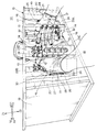
図1および図2において、10はこの発明の実施例1に係る手指リハビリテーション装置で、一方の手(ここでは右手)が健常で、他方の手(ここでは左手)が麻痺している片麻痺の障害者の手指の握り開き(指関節の屈曲および伸展)の運動のリハビリテーションを支援するものである。
手指リハビリテーション装置10は、健常側の右手の五指の先部に1本ずつ装着されるキャップ形状(筒形状)の5つの第1の固定部材11と、麻痺側の左手の五指の先部に1本ずつ装着されるキャップ形状(筒形状)の5つの第2の固定部材12と、各第1の固定部材11とこれらに対応する各第2の固定部材12とを連結する5本のワイヤ(力伝達部材)13を有し、かつ各ワイヤ13を介して、各第1の固定部材11の動作量、各第1の固定部材11の動作速度、障害者の五指の動作方向を基準とした各第1の固定部材11の動作方向がそれぞれ同一となる動作を、各第2の固定部材12へ同時かつメカニカルに伝達する5つの動作伝達手段14と、各動作伝達手段14が内部空間の形成壁に設けられ、かつ各動作伝達手段14を介して、各第1の固定部材11および各第2の固定部材12が、内部空間に収納される本体ケーシング15と、本体ケーシング15の内部空間の形成壁に設けられ、内部空間に挿入された健常側の右手および麻痺側の左手をそれぞれ位置決めする1対の位置決め手段16とを備えている。
1 and 2,
The
以下、これらの構成体を詳細に説明する。
手指リハビリテーション装置10は、それぞれ平面視してX1−X2方向に長い矩形状の上板17および下板18と、側面して略正方形状の両側板19とを有し、かつ前面および背面(後面)が開口された六面箱体の本体ケーシング15を外装材とする。障害者の両手は、開口した前面側の開口から本体ケーシング15の内部空間へ挿入される。また、両側板19のY1−Y2側の両端部は、厚肉な角材により内側から補強されている。そのうち、Y1側に配置された両角材20の長さ方向の略中間部分であって、かつその内側コーナーには、両手首を保護する面取り部21がそれぞれ形成されている。
Hereinafter, these components will be described in detail.
The
本体ケーシング15の内部空間の中央部周辺には、それぞれ4つのプーリ22が上下に所定ピッチで配設された第1〜第4のプーリ群固定柱23A〜23Dと、下端部に右手の載置台24が固定された右手載置台固定柱25と、下端部に左手の載置台24が固定された左手載置台固定柱26とが、平面視して円形状の仮想ラインに沿って、本体ケーシング15の上板17および下板18間に立設されている。このうち、第1のプーリ群固定柱23Aは前記内部空間のX1−Y1方向に配置され、第2のプーリ群固定柱23Bは内部空間のX2−Y2方向に配置されている。また、第3のプーリ群固定柱23Cは内部空間のX2−Y1方向に配置され、第4のプーリ群固定柱23Dは内部空間のX1−Y2方向に配置されている。さらに、右手載置台固定柱25は内部空間のX1方向に配置され、左手載置台固定柱26は内部空間のX2方向に配置されている。各動作伝達手段14は、それぞれの手指に対応する各プーリ22と、これらを支持する第1〜第4のプーリ群固定柱23A〜23Dとにより構成されている。
Around the central portion of the inner space of the
各プーリ群固定柱23A〜23Dは上下方向に長い矩形板で、その長さ方向の中央部一帯に長孔23aが形成されている。各プーリ群固定柱23A〜23Dの内面は、内部空間の中心部aに向いている。各プーリ群固定柱23A〜23Dに配設された4つのプーリ22は、最上段のものから順に人差し指(第二指)用のもの、中指(第三指)用のもの、薬指(第四指)用のもの、小指(第五指)用のものとなっている。また、各プーリ22は、左右1対の長尺なビス24により各プーリ群固定柱23A〜23Dの内面からの離間距離を変更し、ワイヤ13の長さを調整できるように構成されている。
本体ケーシング15の上板17のうち、第1および第3のプーリ群固定柱23A、23Cの固定位置より内部空間の中央部a側の部分には、平面視して長さ方向の一方が内部空間の中央部aへ向いた1対の長孔17aが形成されている。上板17の両長孔17aの形成部には、親指用のプーリ22が両長孔17aに回転自在な収納状態で配設されている。さらに、第1および第3のプーリ群固定柱23A、23Cの各下端部には、各X1−X2方向の両端部の内面に、内部空間の中心部aへ向かって延びた片方が門形の細長い分割台32が1対ずつ固定されている。両分割台32の先端部間および元部間には、1対の別の親指用のプーリ22がそれぞれ横架されている。
Each of the pulley
Of the
また、右手載置台固定柱25および左手載置台固定柱26は、各プーリ群固定柱23A〜23Dより幅方向が長い矩形状の板で、平面視してY2側へ向かうほど互いの間隔が狭くなるハの字形に配置されている。右手載置台固定柱25の下端部の内面には、平面視して矩形状の右手用の載置台24が取り付けられている。また、左手載置台固定柱26の下端部の内面には、平面視して矩形状の左手用の載置台24が取り付けられている。両載置台固定柱25,26の長さ方向の中間部の内面には、Y2方向へ向かって徐々に幅(Z1−Z2方向の長さ)が狭くなった側面視して台形状で、かつ薄肉な1対のガイドレール27が配設されている。両ガイドレール27の幅方向の両端部は、内方へ略45°に折り曲げられている。両ガイドレール27のY1−Y2側の端部には、Z1−Z2方向へ長くかつ長さが異なる開口がそれぞれ形成されている。
Further, the right-hand mounting
右手載置台固定柱25のガイドレール27には、健常側の右手が挿入される第1の手袋28の手甲部に接着された先広がり形状の掛止板29が掛止される。一方、左手載置台固定柱26のガイドレール27には、麻痺側の左手が挿入される第2の手袋30の手甲部に接着された先広がり形状の掛止板29が掛止される。両掛止板29は、先広がり側を指先方向に向けて固定されている。両掛止板29を、先広がり側から両ガイドレール27の幅広の開口へ差し込んで行くことにより、両掛止板29が掛止め動作をすることなく両ガイドレール27に掛止される。各位置決め手段16は、両ガイドレール27と両掛止板29とから構成されている。
第1の手袋28の各指部の先端部分(末節骨の被覆部分)には、キャップ形状の第1の固定部材11がそれぞれ分離不能に固定されている。また、第2の手袋30の各指部の先端部分には、キャップ形状の第2の固定部材12がそれぞれ分離不能に固定されている。また、両手袋28,30の手首を覆う部分には、その手掌側の部分に、両手袋28,30の長さ方向へ延びたスリットが形成されている。また、このスリットの形成部分には、両手袋28,30の手首を覆う部分によって手首を締め付けることで、両手袋28,30と両手の一体感を高める雄部と雌部とからなる2つのホック31が形成されている。
The
Cap-shaped first fixing
5対の両固定部材11,12の先端部には、5本の無端形状のワイヤ13の一部がそれぞれ連結されている。このうち、親指用の両固定部材11,12に連結された1本のワイヤ13は、1対の上側の親指用のプーリ22と、2対の下側の親指用のプーリ22との間で引き回されている。具体的には、図3に示すように右親指用の第1の固定部材11から下方へ引き回されたワイヤ13は、順次、右下側の分割台32の先端部間の親指用のプーリ22、左下側の元部間の親指用のプーリ22、左上側の親指用のプーリ22、左親指用の第2の固定部材12、左下側の分割台32の先端部間の親指用のプーリ22、右下側の分割台32の元部間の親指用のプーリ22、右上側の親指用のプーリ22を順次経由して右親指用の第1の固定部材11に戻る。
また、残りの4対の両固定部材11,12の先端部に連結された4本のワイヤ13は、前記4つの各プーリ群固定柱23A〜23Dに配設された各4つのプーリ22間で引き回されている(図4)。具体的には、人差し指用のワイヤ13が各プーリ群固定柱23A〜23Dの最上段のプーリ22間で引き回され、中指用のワイヤ13が各プーリ群固定柱23A〜23Dの上から2段目のプーリ22間で引き回される。また、薬指用のワイヤ13が各プーリ群固定柱23A〜23Dの3段目のプーリ22間で引き回され、小指用のワイヤ13が各プーリ群固定柱23A〜23Dの上から4段目(最下段)のプーリ22間で引き回される。
A part of five
The four
ここで、人差し指用のワイヤ13を例として、親指用を除いた各ワイヤ13の各プーリ群固定柱23A〜23Dに配設されたプーリ22間での引き回し方法を詳細に説明する。
図4に示すように、例えば、右人差し指用の第1の固定部材11から下方へ引き回されたワイヤ13は、順次、第1のプーリ群固定柱23Aの最上段の人差し指用のプーリ22、第2のプーリ群固定柱23Bの最上段の人差し指用のプーリ22、第3のプーリ群固定柱23Cの最上段の人差し指用のプーリ22、第4のプーリ群固定柱23Dの最上段の人差し指用のプーリ22を順次経由して右人差し指用の第1の固定部材11に戻る。残りの3本の手指も、同じように第1のプーリ群固定柱23Aから第4のプーリ群固定柱23Dへと順に引き回される。
また、両固定部材11,12のワイヤ13に対する具体的な連結構造を説明すれば、両固定部材11,12の先端部の一部分にはワイヤ掛け用のスリットを形成する一方、ワイヤ13のうち、各固定部材11,12が掛止される位置の両側部分に、対応する固定部材11,12の位置決め用の結線をそれぞれ巻回している。このとき、近接した両結線間の隙間は、対応する固定部材11,12をワイヤ13に掛止したとき、両固定部材11,12がガタつかない程度のものとしている。このように構成したことで、障害者の手の大きさに応じて、各ワイヤ13に掛止される両手袋28,30をガタつきなく適宜変更することができる。
Here, taking the
As shown in FIG. 4, for example, the
In addition, a specific connection structure of the fixing
次に、実施例1に係る手指リハビリテーション装置10を使用し、片麻痺した左手の五指の曲げ伸ばし運動に対するリハビリテーション方法を説明する。
図1に示すように、まず障害者は、テーブルに載置された手指リハビリテーション装置10に対面して椅子に座る。この状態で、介助者の介助を受けて第1の手袋28に健常側の右手を挿入し、5つの第1の固定部材11に右手の五指の先部をそれぞれ装着し、第2の手袋30に麻痺側の左手を挿入し、5つの第2の固定部材12に左手の五指をそれぞれ挿入する。両手の挿入後、両手袋28,30の手首を覆う部分において、両ホック31の雄部と雌部とを掛止し、両手首に両手袋28,30の手首を覆う部分を締め付けて堅固に一体化する。次に、両掛止板29を、先細り側から右手載置台固定柱25および左手載置台固定柱26の各ガイドレール27の幅広の開口へ差し込んで行く。これにより、両掛止板29が掛止め動作をすることなく両ガイドレール27に掛止される。この場合、障害者は自力で両手袋28,30の装着および麻痺側の手の位置決めができないため、介助者の介助が必要となる。この状態で、健常側の五指の力により麻痺側の五指の握り開き(指関節の屈曲および伸展)の運動を任意に行う。
Next, a rehabilitation method for bending and extending the five fingers of the hemiplegic left hand using the
As shown in FIG. 1, the disabled person first sits on a chair facing the
このように、両ガイドレール27を、Y2方向へ向かって徐々に幅狭くなった側面視して台形状で、かつその幅方向の両端部が内方へ略45°に折り曲げられたものとし、両掛止板29を、両ガイドレール27の形状と相似形状とし、かつ対応するガイドレール27への差し込み式の嵌合構造となるように構成している。これにより、障害者の手が装着された両手袋28,30を、ワンタッチで両載置台固定柱25,26に位置決めすることができる。
すなわち、例えば健常側の右手の親指(第一指)を握る場合(指関節の屈曲の場合)には、その指の力により親指用の第1の固定部材11とワイヤ13が下方へ移動する。これに伴い、親指用のワイヤ13が一部で襷掛けされながら、図3の実線矢印に示すように各親指用のプーリ22間で引き回される。これにより、麻痺側の左手の親指用の第1の固定部材11を介して左手の親指が握り状態となる(内方へ曲げられる)。
一方、右手の親指を開いた場合(指関節を伸展させた場合)には、その操作力により親指用の第1の固定部材11が上方へ移動される。これに伴い、親指用のワイヤ13が一部で襷掛けされながら、図3の破線矢印のように各親指用のプーリ22間で反対回りに引き回される。これにより、麻痺側の親指用の第1の固定部材11を介して左手の親指が開き状態となる(外方へ伸ばされる)。このようにして、健常側の親指が装着された第1の固定部材11の動作量、第1の固定部材11の動作速度、第1の固定部材11の動作方向がそれぞれ同一となる動作が、麻痺側の親指が装着された第2の固定部材12へ同時かつメカニカルに伝達される。
Thus, both the guide rails 27 are assumed to be trapezoidal in a side view gradually becoming narrower in the Y2 direction, and both end portions in the width direction are bent inward at approximately 45 °, Both the latching
That is, for example, when the thumb (first finger) of the right hand on the healthy side is gripped (when the finger joint is bent), the first fixing
On the other hand, when the thumb of the right hand is opened (when the finger joint is extended), the first fixing
また、健常側の右手のうち、残りの四指(人差指(第二指)〜小指(第五指))を握った場合(指関節の屈曲の場合)には、図4の実線矢印に示すように、4本のワイヤ13が襷掛けされながら各四指用のプーリ22間で引き回され、麻痺側の四指が握り状態となる(曲げられる)。一方、右手の四指を開いた場合(指関節を伸展させた場合)には、図4の破線矢印に示すように、4本のワイヤ13が襷掛けされながら各四指用のプーリ22間で反対回りに引き回され、四指が開き状態となる(伸ばされる)。なお、親指の握り開きの運動と、残りの四指の握り開きの運動とは、引き回された各ワイヤ13同士の干渉による不具合を避けるため、別々に行うものとする。
In addition, when the remaining four fingers (index finger (second finger) to little finger (fifth finger)) of the right hand on the healthy side are gripped (in the case of flexion of the finger joint), a solid line arrow in FIG. As described above, the four
このようにして、健常側の四指が装着された各第1の固定部材11の動作量、各第1の固定部材11の動作速度、各第1の固定部材11の動作方向がそれぞれ同一となる動作が、麻痺側の四指が装着された各第2の固定部材12へ同時かつメカニカルに伝達される。その結果、障害者が健常側の手指の力で麻痺側の手指に所定の関節運動を行わせることができる。これにより、従来のアクチュエータ式のものに比べて脳の回復、再構築の期待が高まる。また、この構成としたことで、リハビリテーションの介助者は、監視程度を行う1人のみでもよい。したがって、医療施設などでの使用時には、1人の介助者で複数人の障害者のリハビリテーションを介助することが可能となり、今日の医師、理学療法士の不足解消に寄与することができる。さらに、障害者は、麻痺側の手指を介助者が動かすことで、鏡を見ながら健常側の手指と麻痺側の手指とが同時に同一方向へ動いている様子を視認することができる。そのため、ミラーセラピーの理論により、手指リハビリテーションの効果を高めることができる。
しかも、麻痺側の手指の可動範囲を超える屈伸動作を強いたり、誤動作および装置の乱調なども無く、リハビリテーション装置としての安全性が高く、施設用および一般家庭用として好適である。
さらに、従来のようなアクチュエータ、曲げセンサ、バルブ、制御ユニットなどが不要となり、装置の低コスト化も図ることができる。
In this way, the operation amount of each first fixing
In addition, there is no force in bending and stretching beyond the range of movement of the fingers on the paralyzed side, no malfunction and device malfunction, and the safety as a rehabilitation device is high, and it is suitable for facilities and general household use.
Furthermore, conventional actuators, bending sensors, valves, control units and the like are not necessary, and the cost of the apparatus can be reduced.
さらにまた、各第1の固定部材11および各第2の固定部材12を筒形状のキャップとしたので、各固定部材11,12を適度な締め付けで五指に装着することができる。これにより、両手袋28,30が抜け難くなり、両手を握ったり開いたとき、各固定部材11,12が五指に緩く装着されたことによる各指の移動範囲の減少を防止することができる。
また、各第1の固定部材11を第1の手袋28に固定し、各第2の固定部材12を第2の手袋30に固定するように構成したので、各5つの両固定部材11,12が本体ケーシング15の内部空間にそれぞれ一まとめの状態で配置することができる。しかも、両手袋28,30に健常側の手や麻痺側の手を通すだけで、各第1の固定部材11および各第2の固定部材12を、対応する手指に装着することができるので、両固定部材11,12の手指への装着が容易となる。また、同じような理由により両固定部材11,12からの手指の取り外しも容易となる。
なお、ワイヤ13の長さの調整は、各プーリ22を第2のプーリ群固定柱23Bおよび第4のプーリ群固定柱23Dに連結するビスのねじ込み量を変更することでなされる。ワイヤ13に緩みがあれば、その分、麻痺側の手指の動作範囲が小さくなる。
Furthermore, since each of the
Further, since each first fixing
The length of the
この発明は、脳卒中、脳外傷などにより片麻痺となった手の手指のリハビリテーションを支援する装置として有用である。 The present invention is useful as an apparatus that supports rehabilitation of a hand that has become hemiplegic due to stroke, brain injury, or the like.
10 手指リハビリテーション装置、
11 第1の固定部材、
12 第2の固定部材、
13 ワイヤ(力伝達部材)、
14 動作伝達手段、
15 本体ケーシング、
16 位置決め手段、
28 第1の手袋、
30 第2の手袋。
10 finger rehabilitation device,
11 First fixing member,
12 Second fixing member,
13 wire (force transmission member),
14 motion transmission means,
15 body casing,
16 positioning means;
28 first gloves,
30 Second glove.
Claims (2)
健常側の手の五指の先部に1本ずつ装着されるキャップ形状またはリング形状の5つの第1の固定部材と、
麻痺側の手の五指の先部に1本ずつ装着されるキャップ形状またはリング形状の5つの第2の固定部材と、
前記各第1の固定部材とこれらに対応する前記各第2の固定部材とを連結する5本の力伝達部材を有し、かつ該各力伝達部材を介して、前記各第1の固定部材の動作量、該各第1の固定部材の動作速度、前記障害者の五指の動作方向を基準とした前記各第1の固定部材の動作方向がそれぞれ同一となる動作を、前記各第2の固定部材へ同時かつメカニカルに伝達する5つの動作伝達手段と、
該各動作伝達手段が内部空間の形成壁に設けられ、かつ前記各第1の固定部材および前記各第2の固定部材が、前記内部空間に収納される本体ケーシングと、
該本体ケーシングの内部空間の形成壁に設けられ、前記内部空間に挿入された前記健常側の手および前記麻痺側の手をそれぞれ位置決めする1対の位置決め手段とを備えた手指リハビリテーション装置。 In a hand rehabilitation device that supports rehabilitation of the hand of a handicapped person with hemiplegia where one hand is healthy and the other hand is paralyzed,
Five cap-shaped or ring-shaped first fixing members that are attached one by one to the tip of five fingers on the healthy hand,
Five second fixing members in the shape of caps or rings that are attached one by one to the tip of five fingers on the paralyzed hand,
Each of the first fixing members has five force transmission members that connect the first fixing members to the second fixing members corresponding to the first fixing members, and the first fixing members via the force transmission members. The movement amount of the first fixing member, the movement speed of the first fixing member, and the movement direction of the first fixing member on the basis of the movement direction of the five fingers of the handicapped person are the same. 5 motion transmitting means for simultaneously and mechanically transmitting to the fixing member;
A body casing in which each of the motion transmitting means is provided on a forming wall of an internal space, and each of the first fixing members and each of the second fixing members is housed in the internal space;
A finger rehabilitation device comprising a pair of positioning means provided on a forming wall of an internal space of the main casing and positioning the healthy hand and the paralyzed hand inserted into the internal space.
麻痺側の手が挿入され、かつ五指が1本ずつ挿入される5つの指部を有した第2の手袋とを有し、
前記各第1の固定部材が、前記第1の手袋の各指部の先部にそれぞれ固定され、
前記各第2の固定部材が、前記第2の手袋の各指部の先部にそれぞれ固定された請求項1に記載の手指リハビリテーション装置。 A first glove having five fingers into which a healthy hand is inserted and five fingers are inserted one by one;
A second glove having five fingers into which a paralyzed hand is inserted and five fingers are inserted one by one;
Each of the first fixing members is fixed to a tip portion of each finger portion of the first glove,
The finger rehabilitation device according to claim 1, wherein each of the second fixing members is fixed to a tip portion of each finger portion of the second glove.
Priority Applications (1)
| Application Number | Priority Date | Filing Date | Title |
|---|---|---|---|
| JP2010269624A JP2012115567A (en) | 2010-12-02 | 2010-12-02 | Finger rehabilitation device |
Applications Claiming Priority (1)
| Application Number | Priority Date | Filing Date | Title |
|---|---|---|---|
| JP2010269624A JP2012115567A (en) | 2010-12-02 | 2010-12-02 | Finger rehabilitation device |
Publications (1)
| Publication Number | Publication Date |
|---|---|
| JP2012115567A true JP2012115567A (en) | 2012-06-21 |
Family
ID=46499152
Family Applications (1)
| Application Number | Title | Priority Date | Filing Date |
|---|---|---|---|
| JP2010269624A Pending JP2012115567A (en) | 2010-12-02 | 2010-12-02 | Finger rehabilitation device |
Country Status (1)
| Country | Link |
|---|---|
| JP (1) | JP2012115567A (en) |
Cited By (2)
| Publication number | Priority date | Publication date | Assignee | Title |
|---|---|---|---|---|
| CN107174478A (en) * | 2017-05-23 | 2017-09-19 | 邱剑波 | A kind of rehabilitation hand equipment taken exercise based on belt wheel all-directional |
| EP4062887A4 (en) * | 2019-12-26 | 2023-05-24 | Shentai Medical Technology (Shanghai) Co., Ltd. | Mirror treatment device and mirror treatment system |
-
2010
- 2010-12-02 JP JP2010269624A patent/JP2012115567A/en active Pending
Cited By (2)
| Publication number | Priority date | Publication date | Assignee | Title |
|---|---|---|---|---|
| CN107174478A (en) * | 2017-05-23 | 2017-09-19 | 邱剑波 | A kind of rehabilitation hand equipment taken exercise based on belt wheel all-directional |
| EP4062887A4 (en) * | 2019-12-26 | 2023-05-24 | Shentai Medical Technology (Shanghai) Co., Ltd. | Mirror treatment device and mirror treatment system |
Similar Documents
| Publication | Publication Date | Title |
|---|---|---|
| Lessard et al. | A soft exosuit for flexible upper-extremity rehabilitation | |
| Lee et al. | Development of a biomimetic hand exotendon device (BiomHED) for restoration of functional hand movement post-stroke | |
| Colombo et al. | Robotic techniques for upper limb evaluation and rehabilitation of stroke patients | |
| Aubin et al. | A pediatric robotic thumb exoskeleton for at-home rehabilitation: the Isolated Orthosis for Thumb Actuation (IOTA) | |
| US10449677B1 (en) | Robotic gripping assist | |
| Gribble et al. | Role of cocontraction in arm movement accuracy | |
| Dovat et al. | HandCARE: a cable-actuated rehabilitation system to train hand function after stroke | |
| Krebs et al. | Therapeutic robotics: A technology push | |
| Tran et al. | Patient-specific, voice-controlled, robotic flexotendon glove-ii system for spinal cord injury | |
| Lu et al. | Advanced myoelectric control for robotic hand-assisted training: outcome from a stroke patient | |
| US20190060099A1 (en) | Wearable and functional hand orthotic | |
| US20200129362A1 (en) | Assistive glove for daily activities of stroke patient | |
| Jiang et al. | Fishbone-inspired soft robotic glove for hand rehabilitation with multi-degrees-of-freedom | |
| He et al. | RUPERT: a device for robotic upper extremity repetitive therapy | |
| Burns et al. | Towards a wearable hand exoskeleton with embedded synergies | |
| AbdulKareem et al. | Recent trends in robotic systems for upper-limb stroke recovery: A low-cost hand and wrist rehabilitation device | |
| Jiralerspong et al. | A novel soft robotic glove for daily life assistance | |
| Abdelhafiz et al. | Bio-inspired tendon driven mechanism for simultaneous finger joints flexion using a soft hand exoskeleton | |
| Jian et al. | Wearable hand exoskeleton for activities of daily living | |
| Silveira et al. | From the past to the future of therapeutic orthoses for upper limbs rehabilitation | |
| Borboni et al. | Compliant device for hand rehabilitation of stroke patient | |
| KR101569000B1 (en) | Finger rehabilitation training robot comprising chopsticks and simulation system using the same | |
| JP2012115567A (en) | Finger rehabilitation device | |
| Wang et al. | Sensor glove implemented with artificial muscle set for hand rehabilitation | |
| Masia et al. | Whole-arm rehabilitation following stroke: Hand module |