JP2012115356A - Femoral component for artificial hip joint - Google Patents
Femoral component for artificial hip joint Download PDFInfo
- Publication number
- JP2012115356A JP2012115356A JP2010265989A JP2010265989A JP2012115356A JP 2012115356 A JP2012115356 A JP 2012115356A JP 2010265989 A JP2010265989 A JP 2010265989A JP 2010265989 A JP2010265989 A JP 2010265989A JP 2012115356 A JP2012115356 A JP 2012115356A
- Authority
- JP
- Japan
- Prior art keywords
- femoral component
- artificial hip
- buffer member
- hip joint
- bone head
- Prior art date
- Legal status (The legal status is an assumption and is not a legal conclusion. Google has not performed a legal analysis and makes no representation as to the accuracy of the status listed.)
- Pending
Links
Images
Classifications
-
- A—HUMAN NECESSITIES
- A61—MEDICAL OR VETERINARY SCIENCE; HYGIENE
- A61F—FILTERS IMPLANTABLE INTO BLOOD VESSELS; PROSTHESES; DEVICES PROVIDING PATENCY TO, OR PREVENTING COLLAPSING OF, TUBULAR STRUCTURES OF THE BODY, e.g. STENTS; ORTHOPAEDIC, NURSING OR CONTRACEPTIVE DEVICES; FOMENTATION; TREATMENT OR PROTECTION OF EYES OR EARS; BANDAGES, DRESSINGS OR ABSORBENT PADS; FIRST-AID KITS
- A61F2/00—Filters implantable into blood vessels; Prostheses, i.e. artificial substitutes or replacements for parts of the body; Appliances for connecting them with the body; Devices providing patency to, or preventing collapsing of, tubular structures of the body, e.g. stents
- A61F2/02—Prostheses implantable into the body
- A61F2/30—Joints
- A61F2/32—Joints for the hip
- A61F2/36—Femoral heads ; Femoral endoprostheses
-
- A—HUMAN NECESSITIES
- A61—MEDICAL OR VETERINARY SCIENCE; HYGIENE
- A61F—FILTERS IMPLANTABLE INTO BLOOD VESSELS; PROSTHESES; DEVICES PROVIDING PATENCY TO, OR PREVENTING COLLAPSING OF, TUBULAR STRUCTURES OF THE BODY, e.g. STENTS; ORTHOPAEDIC, NURSING OR CONTRACEPTIVE DEVICES; FOMENTATION; TREATMENT OR PROTECTION OF EYES OR EARS; BANDAGES, DRESSINGS OR ABSORBENT PADS; FIRST-AID KITS
- A61F2/00—Filters implantable into blood vessels; Prostheses, i.e. artificial substitutes or replacements for parts of the body; Appliances for connecting them with the body; Devices providing patency to, or preventing collapsing of, tubular structures of the body, e.g. stents
- A61F2/02—Prostheses implantable into the body
- A61F2/30—Joints
- A61F2002/30001—Additional features of subject-matter classified in A61F2/28, A61F2/30 and subgroups thereof
Landscapes
- Health & Medical Sciences (AREA)
- Orthopedic Medicine & Surgery (AREA)
- Cardiology (AREA)
- Oral & Maxillofacial Surgery (AREA)
- Transplantation (AREA)
- Engineering & Computer Science (AREA)
- Biomedical Technology (AREA)
- Heart & Thoracic Surgery (AREA)
- Vascular Medicine (AREA)
- Life Sciences & Earth Sciences (AREA)
- Animal Behavior & Ethology (AREA)
- General Health & Medical Sciences (AREA)
- Public Health (AREA)
- Veterinary Medicine (AREA)
- Prostheses (AREA)
Abstract
Description
本発明は、人工股関節において大腿骨側に取り付けられる構成部分に関する。 The present invention relates to a component attached to the femur side in an artificial hip joint.
人工股関節は、骨盤側に設けられる人工骨頭の受けとなるカップ状の臼蓋コンポーネントと、大腿骨側に設けられる人工の骨頭を有する大腿骨コンポーネントとから構成される。また、場合によっては、臼蓋軟骨をそのまま用い、大腿骨コンポーネントのみを置換する場合もある。
図8に大腿骨コンポーネントAが大腿骨Fに固定された状態を示す縦断面図を示す。大腿骨コンポーネントは、骨頭としての機能を果たす球状体からなる骨頭部Hと、大腿骨Fに埋め込まれ、骨頭部の土台となるステム部Sとから構成される。
ステム部Sの先端側には円錐台状の突起Saが設けられるとともに、骨頭部Hには、突起Saに嵌る形状を有する孔Haが設けられ、ステム部Sと骨頭部Hとは突起Saに穴Haが嵌合することで固定されている。
The hip prosthesis is composed of a cup-shaped acetabular component that receives an artificial bone head provided on the pelvis side, and a femoral component having an artificial bone head provided on the femur side. In some cases, the acetabular cartilage is used as it is, and only the femoral component is replaced.
FIG. 8 is a longitudinal sectional view showing a state in which the femoral component A is fixed to the femur F. The femoral component includes a bone head H made of a spherical body that functions as a bone head, and a stem portion S that is embedded in the femur F and serves as the foundation of the bone head.
A truncated cone-shaped projection Sa is provided on the distal end side of the stem portion S, and a hole Ha having a shape that fits the projection Sa is provided in the bone head H. The stem portion S and the bone head H are formed on the projection Sa. The hole Ha is fixed by fitting.
ステム部Sと骨頭部Hとはともに硬質の素材により形成され、これらが嵌合により直接接触して固定されているために、骨頭部Hにかかる力は、ほぼすべてステム部Sに伝わる。このような大腿骨Fに埋め込まれるステム部Sにかかる力は、ステム部Sと大腿骨Fとの接着面において、接着の緩みや、マイクロモーションを誘発し、ステム部Sの磨耗や折損の一因となったり、大腿部痛や大腿骨骨折の一因となったりしていると考えられる。
逆に、ステム部Sにかかる力も骨頭部Hに減衰することなく伝達するため、これも人工股関節置換術後の患者に対する臼蓋コンポーネントの緩みの一因となったり、人工骨頭置換術後の患者に対する臼蓋軟骨の変形や変形間接症の一因となったりしていると考えられる。
本発明は、このような観点に立ち、人工股関節の大腿骨コンポーネントにおいて、ステム部と骨頭部との間に伝わる力を緩和することを課題とする。
The stem portion S and the bone head H are both formed of a hard material, and since these are directly contacted and fixed by fitting, almost all the force applied to the bone head H is transmitted to the stem portion S. Such a force applied to the stem portion S embedded in the femur F induces loosening of the adhesion and micromotion on the adhesion surface between the stem portion S and the femur F, and the stem portion S is worn or broken. It is thought that it is a cause, and it is contributed to a thigh pain and a femur fracture.
On the contrary, since the force applied to the stem S is transmitted to the bone head H without being attenuated, this also contributes to the loosening of the acetabular component relative to the patient after the hip replacement or the patient after the hip replacement. It is thought that it contributes to deformation of acetabular cartilage and deformity indirect disease.
In view of such a viewpoint, an object of the present invention is to alleviate a force transmitted between a stem portion and a bone head in a femoral component of an artificial hip joint.
上記課題を解決するために、本発明は次のような構成を有する。
請求項1に記載の発明は、嵌入孔が設けられた球状体からなる骨頭部と、先端に前記嵌入孔に嵌め入れて固定する当該嵌入孔に嵌る大きさ及び形状を有する係合ネックが形成された、大腿骨に埋め込まれるステム部と、相対する前記嵌入孔内面と前記係合ネック外面との間の少なくとも一部に狭持される薄い、粘弾性体又は前記骨頭部及びステム部より弾性変形しやすい弾性体からなる緩衝部材とを有する人工股関節用大腿骨コンポーネントである。
請求項2に記載の発明は、前記人工股関節用大腿骨コンポーネントにおいて、前記緩衝部材は少なくとも前記係合ネックの側周面を一周するように設けられるものである。
請求項3に記載の発明は、前記人工股関節用大腿骨コンポーネントにおいて、前記緩衝部材は少なくとも前記嵌入孔の底面に設けられるものである。
請求項4に記載の発明は、前記人工股関節用大腿骨コンポーネントにおいて、前記緩衝部材には抗生物質が添加されるものである。
請求項5に記載の発明は、前記人工股関節用大腿骨コンポーネントと、前記骨頭部を回動可能に保持するカップを有する臼蓋コンポーネントとからなる人工股関節である。
In order to solve the above problems, the present invention has the following configuration.
According to the first aspect of the present invention, there is formed a bone head made of a spherical body provided with an insertion hole, and an engagement neck having a size and a shape that fits into the insertion hole that is fitted into the insertion hole and fixed to the distal end. A thin, viscoelastic body sandwiched between at least part of the stem portion embedded in the femur and the opposed inner surface of the insertion hole and the outer surface of the engagement neck, or more elastic than the bone head and stem portion This is a femoral component for an artificial hip joint having a cushioning member made of an elastic body that is easily deformed.
According to a second aspect of the present invention, in the femoral component for an artificial hip joint, the buffer member is provided so as to go around the side peripheral surface of the engagement neck at least.
According to a third aspect of the present invention, in the femoral component for an artificial hip joint, the buffer member is provided at least on the bottom surface of the insertion hole.
According to a fourth aspect of the present invention, in the femoral component for an artificial hip joint, an antibiotic is added to the cushioning member.
The invention according to claim 5 is an artificial hip joint comprising the femoral component for an artificial hip joint and a acetabular component having a cup for rotatably holding the bone head.
請求項1に記載の発明は、ステム部の係合ネックと、骨頭部の嵌入孔との相対する面の少なくとも一部に粘弾性体からなる緩衝部材が狭持されるので、この接触面においては、ステム部と骨頭部間の間に伝わる力は、粘弾性体又は弾性体からなる緩衝部材が弾性変形やクリープ変形をすることにより緩和される。これにより、ステム部と大腿骨との接着の緩みやマイクロモーションが抑制され、ステム部の磨耗・折損、大腿部痛、大腿骨骨折、大腿骨の変形、臼蓋コンポーネントの緩み、臼蓋軟骨の変形等を抑制することができる。
請求項2に記載の発明は、緩衝部材を係合ネックの周面を一周するように設けることで、係合ネックの側方から加わる全方位の力を緩和することができる。
請求項3に記載の発明は、緩衝部材を嵌入孔の底面に設けることで、係合ネックの中心軸方向に加わる力を緩和することができる。
請求項4に記載の発明は、緩衝部材に抗生物質を添加することで、人工股関節置換術又は人工骨頭置換術をセメントレスにて施術する場合でも、周囲の組織や組織液及び血液中への抗生物質の長時間に渡る徐放が行なわれ、術後の感染症の発生を抑制することができる。
請求項5に記載の発明は、人工股関節において、上記のような効果を奏することができる。
According to the first aspect of the present invention, since the buffer member made of a viscoelastic body is sandwiched between at least a part of the opposing surfaces of the engagement neck of the stem portion and the insertion hole of the bone head, The force transmitted between the stem portion and the bone head is alleviated by the elastic deformation or the creep deformation of the buffer member made of the viscoelastic body or the elastic body. As a result, loosening and micromotion of the adhesion between the stem part and the femur are suppressed, wear and tear of the stem part, thigh pain, femoral fracture, femoral deformation, acetabular component loosening, acetabular cartilage Can be suppressed.
According to the second aspect of the present invention, by providing the buffer member so as to go around the peripheral surface of the engagement neck, the force in all directions applied from the side of the engagement neck can be reduced.
The invention according to claim 3 can relieve the force applied in the central axis direction of the engagement neck by providing the buffer member on the bottom surface of the insertion hole.
In the invention according to claim 4, even when an artificial hip joint replacement or artificial head replacement is performed without cement by adding an antibiotic to the buffer member, antibiotics into surrounding tissues, tissue fluids and blood are used. Sustained release of the substance over a long period of time is performed, and postoperative infection can be suppressed.
The invention according to claim 5 can achieve the above-described effects in an artificial hip joint.
以下、本発明の実施の形態について、図面を参照しながら説明する。
図1に本実施形態に係る人工股関節用大腿骨コンポーネントX(以下、大腿骨コンポーネントXと称する)の縦断面図を示す。大腿骨コンポーネントXは、骨頭部10、ステム部20、緩衝部材30とから構成される。図2に大腿骨コンポーネントXの先端部分の拡大縦断面図を示し、図3に大腿骨コンポーネントXの先端部分の拡大分解縦断面図を示す。
骨頭部10は球体状の金属やセラミック等から構成され、下面側に内部に向かって縮径する円錐台の外面に合致する内壁が形成された嵌入孔11が設けられている。なお、大腿骨コンポーネントXは、骨頭部10を回動可能に保持するカップを有する従来の臼蓋コンポーネントと組み合わせることで人工股関節を構成することができる。
ステム部20は金属からなり、棒状体からなる大腿骨に埋め込まれて固定されるステム本体21と、ステム本体21の先端に大腿骨の骨頭が存する角度に合致する方向に突出するように設けられる係合ネック22とから構成される。係合ネック22は骨頭部10の嵌入孔11の内周面に相似でやや小さい外面を有する円錐台状に形成される。
Hereinafter, embodiments of the present invention will be described with reference to the drawings.
FIG. 1 shows a longitudinal sectional view of a femoral component X for artificial hip joint according to the present embodiment (hereinafter referred to as a femoral component X). The femoral component X includes a
The
The
緩衝部材30は粘弾性体からなる上方に向かって縮径する上面が閉じられた円筒状の部材である。緩衝部材30は粘弾性体の他に、骨頭部10及びステム部20よりも弾性変形しやすい弾性体から形成してもよい。緩衝部材30に用いられる具体的な素材としては、ポリメチルメタクリレート、ポリエチレン、エラストマー、ポリウレタン、ウレタンゲルなどが例示される。緩衝部材30の内面はステム部20の係合ネック22の外面とほぼ合致する形状を有し、緩衝部材30の外面の先端側は骨頭部10の嵌入孔11の内周面とほぼ合致する形状を有する。これにより、緩衝部材30は係合ネック22の外面に嵌合固定され、骨頭部10の嵌入孔11は緩衝部材30の外面に嵌合固定されることとなる。即ち、緩衝部材30は、嵌入孔11と係合ネック22との間に狭持される。また、緩衝部材30は、成形硬化前に抗生物質が添加されている。緩衝部材30は、硬化した状態のものを係合ネック22及び嵌入孔11に嵌めてもよく、また、ゲル状物、粘土状物、液状物から硬化する素材を用いる場合は、硬化前のゲル状又は粘土状のものを係合ネック22の外面や嵌入孔11の内面に塗るか、硬化前の液状のものを嵌入孔11に入れ、その後、両者を嵌め合わせて硬化させることで形状を成形すると同時に係合ネック22と嵌入孔11との間に狭持固定されるようにしてもよい。
The
次に、以上のような構成を有する大腿骨コンポーネントXの作用効果について説明する。大腿骨コンポーネントXの使用方法は、従来の大腿骨コンポーネントの人工股関節置換術や人工骨頭置換術等における使用方法と同じであり、大腿骨から骨頭部分を切除して髄腔を整えてステム本体21を大腿骨に挿入して固定する。なお、緩衝部材30と骨頭部10は、大腿骨に挿入固定する前に係合ネック22に固定しておいてもよく、ステム部20を大腿骨に固定した後に、係合ネック22に固定してもよい。
このようにして、大腿骨に固定された大腿骨コンポーネントXは、骨頭部10からステム部20へ伝わる力及びステム部20から大腿骨部20へ伝わる力が、緩衝部材30の弾性変形やクリープ変形により緩和されるので、ステム部Sの磨耗や折損、大腿部痛、大腿骨骨折、臼蓋コンポーネントの緩み、臼蓋軟骨の変形などの発生を抑制することができる。
Next, the effect of the femoral component X having the above configuration will be described. The method of using the femoral component X is the same as the conventional method of using a femoral component for hip replacement, artificial head replacement, and the like. Is inserted into the femur and fixed. The
In this manner, the femoral component X fixed to the femur has the elastic force and the creep deformation of the
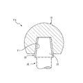
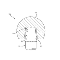
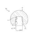
なお、上記実施形態では緩衝部材30は、係合ネック22の上面および側周面全体に渡って設けられているが、緩衝部材30の形状は種々の変形が可能である。例えば、図4に示す大腿骨コンポーネントXaのように係合ネック22の側周面のみに緩衝部材30を設けるような構成としてもよく、図5に示す大腿骨コンポーネントXbのように係合ネック22の上面のみに緩衝部材30を設けるような構成としてもよい。また、側周面を構成する緩衝部材30の長さも適宜変更することができ、図6、図7に示す大腿骨コンポーネントXc、Xdのように、骨頭部10の嵌入孔11内に収まるような長さとしてもよい。
In the above embodiment, the
X、Xa、Xb、Xc、Xd 人工股関節用大腿骨コンポーネント
10 骨頭部
11 嵌入孔
20 ステム部
21 ステム本体
22 係合ネック
30 衝撃吸収材
X, Xa, Xb, Xc, Xd Hip component for
Claims (5)
先端に前記嵌入孔に嵌め入れて固定する当該嵌入孔に嵌る大きさ及び形状を有する係合ネックが形成された、大腿骨に埋め込まれるステム部と、
相対する前記嵌入孔内面と前記係合ネック外面との間の少なくとも一部に狭持される薄い、粘弾性体又は前記骨頭部及びステム部より弾性変形しやすい弾性体からなる緩衝部材と
を有する人工股関節用大腿骨コンポーネント。 A bone head made of a spherical body provided with a fitting hole;
A stem portion embedded in the femur, in which an engagement neck having a size and a shape that fits into the insertion hole that is fitted into and fixed to the insertion hole at a distal end is formed;
And a buffer member made of a thin, viscoelastic body or an elastic body that is more easily elastically deformed than the bone head and stem, and is sandwiched between at least a part between the inner surface of the fitting hole and the outer surface of the engagement neck. Femoral component for artificial hip joints.
Priority Applications (1)
| Application Number | Priority Date | Filing Date | Title |
|---|---|---|---|
| JP2010265989A JP2012115356A (en) | 2010-11-30 | 2010-11-30 | Femoral component for artificial hip joint |
Applications Claiming Priority (1)
| Application Number | Priority Date | Filing Date | Title |
|---|---|---|---|
| JP2010265989A JP2012115356A (en) | 2010-11-30 | 2010-11-30 | Femoral component for artificial hip joint |
Publications (2)
| Publication Number | Publication Date |
|---|---|
| JP2012115356A true JP2012115356A (en) | 2012-06-21 |
| JP2012115356A5 JP2012115356A5 (en) | 2013-12-05 |
Family
ID=46498971
Family Applications (1)
| Application Number | Title | Priority Date | Filing Date |
|---|---|---|---|
| JP2010265989A Pending JP2012115356A (en) | 2010-11-30 | 2010-11-30 | Femoral component for artificial hip joint |
Country Status (1)
| Country | Link |
|---|---|
| JP (1) | JP2012115356A (en) |
Cited By (4)
| Publication number | Priority date | Publication date | Assignee | Title |
|---|---|---|---|---|
| JP2014176687A (en) * | 2013-03-14 | 2014-09-25 | Depuy Synthes Products Llc | Femoral component for implantable hip prosthesis |
| JP2017000291A (en) * | 2015-06-05 | 2017-01-05 | 京セラメディカル株式会社 | Artificial hip joint having electrical insulation sleeve |
| JP2018519885A (en) * | 2015-06-07 | 2018-07-26 | ジョイント イノベイション テクノロジー,エルエルシー | Morse taper protective sleeve |
| US10213310B2 (en) | 2012-06-18 | 2019-02-26 | DePuy Synthes Products, Inc. | Dual modulus hip stem and method of making the same |
Citations (4)
| Publication number | Priority date | Publication date | Assignee | Title |
|---|---|---|---|---|
| JPS53146499A (en) * | 1977-05-23 | 1978-12-20 | Sulzer Ag | Coupling of transplanted materials different in characteristics |
| JPH02213342A (en) * | 1989-02-14 | 1990-08-24 | Ngk Spark Plug Co Ltd | Artificial hip joint |
| JPH08168502A (en) * | 1994-07-14 | 1996-07-02 | Merck Patent Gmbh | Femur prosthesis |
| JPH1043219A (en) * | 1996-05-11 | 1998-02-17 | Heraeus Kulzer Gmbh | Semifinished product for manufacturing prosthesis to be embedded with accurate fit, manufacture therefor, manufacture for prosthesis to be embedded in bone cavity and coxa inner prosthesis |
-
2010
- 2010-11-30 JP JP2010265989A patent/JP2012115356A/en active Pending
Patent Citations (4)
| Publication number | Priority date | Publication date | Assignee | Title |
|---|---|---|---|---|
| JPS53146499A (en) * | 1977-05-23 | 1978-12-20 | Sulzer Ag | Coupling of transplanted materials different in characteristics |
| JPH02213342A (en) * | 1989-02-14 | 1990-08-24 | Ngk Spark Plug Co Ltd | Artificial hip joint |
| JPH08168502A (en) * | 1994-07-14 | 1996-07-02 | Merck Patent Gmbh | Femur prosthesis |
| JPH1043219A (en) * | 1996-05-11 | 1998-02-17 | Heraeus Kulzer Gmbh | Semifinished product for manufacturing prosthesis to be embedded with accurate fit, manufacture therefor, manufacture for prosthesis to be embedded in bone cavity and coxa inner prosthesis |
Cited By (7)
| Publication number | Priority date | Publication date | Assignee | Title |
|---|---|---|---|---|
| US10213310B2 (en) | 2012-06-18 | 2019-02-26 | DePuy Synthes Products, Inc. | Dual modulus hip stem and method of making the same |
| JP2014176687A (en) * | 2013-03-14 | 2014-09-25 | Depuy Synthes Products Llc | Femoral component for implantable hip prosthesis |
| JP2018198958A (en) * | 2013-03-14 | 2018-12-20 | デピュイ・シンセス・プロダクツ・インコーポレイテッド | Femoral component for implantable hip prosthesis |
| US10213314B2 (en) | 2013-03-14 | 2019-02-26 | DePuy Synthes Products, Inc. | Femoral component for an implantable hip prosthesis |
| US11058543B2 (en) | 2013-03-14 | 2021-07-13 | DePuy Synthes Products, Inc. | Femoral component for an implantable hip prosthesis and method of making same |
| JP2017000291A (en) * | 2015-06-05 | 2017-01-05 | 京セラメディカル株式会社 | Artificial hip joint having electrical insulation sleeve |
| JP2018519885A (en) * | 2015-06-07 | 2018-07-26 | ジョイント イノベイション テクノロジー,エルエルシー | Morse taper protective sleeve |
Similar Documents
| Publication | Publication Date | Title |
|---|---|---|
| US5735905A (en) | Shock absorbing element for a load bearing prosthesis | |
| US20030014123A1 (en) | Cementless hip joint endoprosthesis as a surface replacement for the proximal femur | |
| CN104042361A (en) | Femoral Component For An Implantable Hip Prosthesis | |
| WO2007084842A3 (en) | Devices and methods for disc replacement | |
| JP2013526375A (en) | Revision hip implant and prosthesis system | |
| AU2008247066A1 (en) | Cotyle comprising a sterile interface | |
| CN105662655A (en) | Hand and foot bone defect implant | |
| ATE292941T1 (en) | AN ORTHOPEDIC JOINT PROSTHESIS | |
| JP2012115356A (en) | Femoral component for artificial hip joint | |
| ATE504265T1 (en) | IMPLANTATION KIT FOR AN ORTHOPEDIC JOINT PROSTHESIS | |
| WO2009062671A3 (en) | Implant and method for coating an implant | |
| NZ759253A (en) | Reconfigurable hip prosthesis, method of use and kit | |
| NZ770503A (en) | Femoral cup impactor assembly and method and kit for femoral cup impactor | |
| EP2801339A1 (en) | Improved hip replacement | |
| JP2012115356A5 (en) | ||
| CN104434343A (en) | Femoral stem prosthesis | |
| CN101505688A (en) | Asymmetric formation of sockets and/or socket inserts for the manipulation and suppression of natural frequencies | |
| RU2020130866A (en) | HIP JOINT DEVICE AND METHOD | |
| KR101281446B1 (en) | distal modular femoral stem used by isoelastic nonmetal rod or bioabsorbable rod | |
| CN110368145B (en) | Finger joint prosthesis | |
| JP4599311B2 (en) | Hip component for hip prosthesis | |
| CN117257529B (en) | Tantalum coating hip joint prosthesis system | |
| JP2018130427A (en) | Stem for artificial hip joint and artificial hip joint | |
| CN109223254A (en) | A kind of new titanium alloy knuckle support applying calcium phosphate bioactive ceramics | |
| JPH1156884A (en) | Artificial hip joint |
Legal Events
| Date | Code | Title | Description |
|---|---|---|---|
| A521 | Written amendment |
Free format text: JAPANESE INTERMEDIATE CODE: A523 Effective date: 20131017 |
|
| A621 | Written request for application examination |
Free format text: JAPANESE INTERMEDIATE CODE: A621 Effective date: 20131017 |
|
| A871 | Explanation of circumstances concerning accelerated examination |
Free format text: JAPANESE INTERMEDIATE CODE: A871 Effective date: 20131017 |
|
| A975 | Report on accelerated examination |
Free format text: JAPANESE INTERMEDIATE CODE: A971005 Effective date: 20131114 |
|
| A131 | Notification of reasons for refusal |
Free format text: JAPANESE INTERMEDIATE CODE: A131 Effective date: 20131210 |
|
| A02 | Decision of refusal |
Free format text: JAPANESE INTERMEDIATE CODE: A02 Effective date: 20140527 |


