JP2012114086A - Gel electrolyte for dye-sensitized solar cell, and dye-sensitized solar cell including the same - Google Patents
Gel electrolyte for dye-sensitized solar cell, and dye-sensitized solar cell including the same Download PDFInfo
- Publication number
- JP2012114086A JP2012114086A JP2011247097A JP2011247097A JP2012114086A JP 2012114086 A JP2012114086 A JP 2012114086A JP 2011247097 A JP2011247097 A JP 2011247097A JP 2011247097 A JP2011247097 A JP 2011247097A JP 2012114086 A JP2012114086 A JP 2012114086A
- Authority
- JP
- Japan
- Prior art keywords
- iodide
- dye
- electrolyte
- solar cell
- sensitized solar
- Prior art date
- Legal status (The legal status is an assumption and is not a legal conclusion. Google has not performed a legal analysis and makes no representation as to the accuracy of the status listed.)
- Pending
Links
- 239000011245 gel electrolyte Substances 0.000 title claims abstract description 20
- ZCYVEMRRCGMTRW-UHFFFAOYSA-N 7553-56-2 Chemical compound [I] ZCYVEMRRCGMTRW-UHFFFAOYSA-N 0.000 claims abstract description 38
- 239000011630 iodine Substances 0.000 claims abstract description 38
- 229910052740 iodine Inorganic materials 0.000 claims abstract description 38
- 229920000642 polymer Polymers 0.000 claims abstract description 37
- 239000002105 nanoparticle Substances 0.000 claims abstract description 26
- 238000009835 boiling Methods 0.000 claims abstract description 18
- 239000003960 organic solvent Substances 0.000 claims abstract description 14
- XMBWDFGMSWQBCA-UHFFFAOYSA-N hydrogen iodide Chemical compound I XMBWDFGMSWQBCA-UHFFFAOYSA-N 0.000 claims abstract description 13
- 239000003792 electrolyte Substances 0.000 claims description 86
- 230000031700 light absorption Effects 0.000 claims description 18
- SECXISVLQFMRJM-UHFFFAOYSA-N N-Methylpyrrolidone Chemical compound CN1CCCC1=O SECXISVLQFMRJM-UHFFFAOYSA-N 0.000 claims description 15
- 239000002245 particle Substances 0.000 claims description 12
- GWEVSGVZZGPLCZ-UHFFFAOYSA-N Titan oxide Chemical compound O=[Ti]=O GWEVSGVZZGPLCZ-UHFFFAOYSA-N 0.000 claims description 11
- 239000002904 solvent Substances 0.000 claims description 8
- 239000000654 additive Substances 0.000 claims description 7
- QJGQUHMNIGDVPM-UHFFFAOYSA-N nitrogen group Chemical group [N] QJGQUHMNIGDVPM-UHFFFAOYSA-N 0.000 claims description 7
- RAXXELZNTBOGNW-UHFFFAOYSA-N imidazole Natural products C1=CNC=N1 RAXXELZNTBOGNW-UHFFFAOYSA-N 0.000 claims description 6
- NLKNQRATVPKPDG-UHFFFAOYSA-M potassium iodide Chemical compound [K+].[I-] NLKNQRATVPKPDG-UHFFFAOYSA-M 0.000 claims description 6
- FVAUCKIRQBBSSJ-UHFFFAOYSA-M sodium iodide Chemical compound [Na+].[I-] FVAUCKIRQBBSSJ-UHFFFAOYSA-M 0.000 claims description 6
- 230000000996 additive effect Effects 0.000 claims description 5
- 229920000036 polyvinylpyrrolidone Polymers 0.000 claims description 5
- 239000001267 polyvinylpyrrolidone Substances 0.000 claims description 5
- 235000013855 polyvinylpyrrolidone Nutrition 0.000 claims description 5
- 239000000126 substance Substances 0.000 claims description 5
- GCMNJUJAKQGROZ-UHFFFAOYSA-N 1,2-Dihydroquinolin-2-imine Chemical compound C1=CC=CC2=NC(N)=CC=C21 GCMNJUJAKQGROZ-UHFFFAOYSA-N 0.000 claims description 4
- KYQCOXFCLRTKLS-UHFFFAOYSA-N Pyrazine Chemical compound C1=CN=CC=N1 KYQCOXFCLRTKLS-UHFFFAOYSA-N 0.000 claims description 4
- VYPSYNLAJGMNEJ-UHFFFAOYSA-N Silicium dioxide Chemical compound O=[Si]=O VYPSYNLAJGMNEJ-UHFFFAOYSA-N 0.000 claims description 4
- 125000000217 alkyl group Chemical group 0.000 claims description 4
- UAYWVJHJZHQCIE-UHFFFAOYSA-L zinc iodide Chemical compound I[Zn]I UAYWVJHJZHQCIE-UHFFFAOYSA-L 0.000 claims description 4
- OOWFYDWAMOKVSF-UHFFFAOYSA-N 3-methoxypropanenitrile Chemical group COCCC#N OOWFYDWAMOKVSF-UHFFFAOYSA-N 0.000 claims description 3
- GBBZLMLLFVFKJM-UHFFFAOYSA-N 1,2-diiodoethane Chemical compound ICCI GBBZLMLLFVFKJM-UHFFFAOYSA-N 0.000 claims description 2
- JIHQDMXYYFUGFV-UHFFFAOYSA-N 1,3,5-triazine Chemical compound C1=NC=NC=N1 JIHQDMXYYFUGFV-UHFFFAOYSA-N 0.000 claims description 2
- BTUGGGLMQBJCBN-UHFFFAOYSA-N 1-iodo-2-methylpropane Chemical compound CC(C)CI BTUGGGLMQBJCBN-UHFFFAOYSA-N 0.000 claims description 2
- QWENRTYMTSOGBR-UHFFFAOYSA-N 1H-1,2,3-Triazole Chemical compound C=1C=NNN=1 QWENRTYMTSOGBR-UHFFFAOYSA-N 0.000 claims description 2
- JBOIAZWJIACNJF-UHFFFAOYSA-N 1h-imidazole;hydroiodide Chemical compound [I-].[NH2+]1C=CN=C1 JBOIAZWJIACNJF-UHFFFAOYSA-N 0.000 claims description 2
- XZXYQEHISUMZAT-UHFFFAOYSA-N 2-[(2-hydroxy-5-methylphenyl)methyl]-4-methylphenol Chemical compound CC1=CC=C(O)C(CC=2C(=CC=C(C)C=2)O)=C1 XZXYQEHISUMZAT-UHFFFAOYSA-N 0.000 claims description 2
- LWMDPZVQAMQFOC-UHFFFAOYSA-N 4-butylpyridine Chemical compound CCCCC1=CC=NC=C1 LWMDPZVQAMQFOC-UHFFFAOYSA-N 0.000 claims description 2
- NSPMIYGKQJPBQR-UHFFFAOYSA-N 4H-1,2,4-triazole Chemical compound C=1N=CNN=1 NSPMIYGKQJPBQR-UHFFFAOYSA-N 0.000 claims description 2
- UNMYWSMUMWPJLR-UHFFFAOYSA-L Calcium iodide Chemical compound [Ca+2].[I-].[I-] UNMYWSMUMWPJLR-UHFFFAOYSA-L 0.000 claims description 2
- IAYPIBMASNFSPL-UHFFFAOYSA-N Ethylene oxide Chemical compound C1CO1 IAYPIBMASNFSPL-UHFFFAOYSA-N 0.000 claims description 2
- PCNDJXKNXGMECE-UHFFFAOYSA-N Phenazine Natural products C1=CC=CC2=NC3=CC=CC=C3N=C21 PCNDJXKNXGMECE-UHFFFAOYSA-N 0.000 claims description 2
- 239000004952 Polyamide Substances 0.000 claims description 2
- 239000004372 Polyvinyl alcohol Substances 0.000 claims description 2
- WTKZEGDFNFYCGP-UHFFFAOYSA-N Pyrazole Chemical compound C=1C=NNC=1 WTKZEGDFNFYCGP-UHFFFAOYSA-N 0.000 claims description 2
- CZPWVGJYEJSRLH-UHFFFAOYSA-N Pyrimidine Chemical compound C1=CN=CN=C1 CZPWVGJYEJSRLH-UHFFFAOYSA-N 0.000 claims description 2
- HFEHLDPGIKPNKL-UHFFFAOYSA-N allyl iodide Chemical compound ICC=C HFEHLDPGIKPNKL-UHFFFAOYSA-N 0.000 claims description 2
- 229940107816 ammonium iodide Drugs 0.000 claims description 2
- SGUXGJPBTNFBAD-UHFFFAOYSA-L barium iodide Chemical compound [I-].[I-].[Ba+2] SGUXGJPBTNFBAD-UHFFFAOYSA-L 0.000 claims description 2
- 229910001638 barium iodide Inorganic materials 0.000 claims description 2
- 229940075444 barium iodide Drugs 0.000 claims description 2
- XQPRBTXUXXVTKB-UHFFFAOYSA-M caesium iodide Chemical compound [I-].[Cs+] XQPRBTXUXXVTKB-UHFFFAOYSA-M 0.000 claims description 2
- 229910001640 calcium iodide Inorganic materials 0.000 claims description 2
- 229940046413 calcium iodide Drugs 0.000 claims description 2
- 229920001577 copolymer Polymers 0.000 claims description 2
- GBRBMTNGQBKBQE-UHFFFAOYSA-L copper;diiodide Chemical compound I[Cu]I GBRBMTNGQBKBQE-UHFFFAOYSA-L 0.000 claims description 2
- NZZFYRREKKOMAT-UHFFFAOYSA-N diiodomethane Chemical compound ICI NZZFYRREKKOMAT-UHFFFAOYSA-N 0.000 claims description 2
- 150000004676 glycans Chemical class 0.000 claims description 2
- ILVUABTVETXVMV-UHFFFAOYSA-N hydron;bromide;iodide Chemical compound Br.I ILVUABTVETXVMV-UHFFFAOYSA-N 0.000 claims description 2
- AMGQUBHHOARCQH-UHFFFAOYSA-N indium;oxotin Chemical compound [In].[Sn]=O AMGQUBHHOARCQH-UHFFFAOYSA-N 0.000 claims description 2
- XMBWDFGMSWQBCA-UHFFFAOYSA-M iodide Chemical compound [I-] XMBWDFGMSWQBCA-UHFFFAOYSA-M 0.000 claims description 2
- HVTICUPFWKNHNG-UHFFFAOYSA-N iodoethane Chemical compound CCI HVTICUPFWKNHNG-UHFFFAOYSA-N 0.000 claims description 2
- INQOMBQAUSQDDS-UHFFFAOYSA-N iodomethane Chemical compound IC INQOMBQAUSQDDS-UHFFFAOYSA-N 0.000 claims description 2
- XJTQJERLRPWUGL-UHFFFAOYSA-N iodomethylbenzene Chemical compound ICC1=CC=CC=C1 XJTQJERLRPWUGL-UHFFFAOYSA-N 0.000 claims description 2
- BQZGVMWPHXIKEQ-UHFFFAOYSA-L iron(ii) iodide Chemical compound [Fe+2].[I-].[I-] BQZGVMWPHXIKEQ-UHFFFAOYSA-L 0.000 claims description 2
- FMKOJHQHASLBPH-UHFFFAOYSA-N isopropyl iodide Chemical compound CC(C)I FMKOJHQHASLBPH-UHFFFAOYSA-N 0.000 claims description 2
- HSZCZNFXUDYRKD-UHFFFAOYSA-M lithium iodide Chemical group [Li+].[I-] HSZCZNFXUDYRKD-UHFFFAOYSA-M 0.000 claims description 2
- BLQJIBCZHWBKSL-UHFFFAOYSA-L magnesium iodide Chemical compound [Mg+2].[I-].[I-] BLQJIBCZHWBKSL-UHFFFAOYSA-L 0.000 claims description 2
- 229910001641 magnesium iodide Inorganic materials 0.000 claims description 2
- QWYFOIJABGVEFP-UHFFFAOYSA-L manganese(ii) iodide Chemical compound [Mn+2].[I-].[I-] QWYFOIJABGVEFP-UHFFFAOYSA-L 0.000 claims description 2
- QKEOZZYXWAIQFO-UHFFFAOYSA-M mercury(1+);iodide Chemical compound [Hg]I QKEOZZYXWAIQFO-UHFFFAOYSA-M 0.000 claims description 2
- 229920002647 polyamide Polymers 0.000 claims description 2
- 229920001282 polysaccharide Polymers 0.000 claims description 2
- 239000005017 polysaccharide Substances 0.000 claims description 2
- 229920002451 polyvinyl alcohol Polymers 0.000 claims description 2
- 229920002717 polyvinylpyridine Polymers 0.000 claims description 2
- PBMFSQRYOILNGV-UHFFFAOYSA-N pyridazine Chemical compound C1=CC=NN=C1 PBMFSQRYOILNGV-UHFFFAOYSA-N 0.000 claims description 2
- BJDYCCHRZIFCGN-UHFFFAOYSA-N pyridin-1-ium;iodide Chemical compound I.C1=CC=NC=C1 BJDYCCHRZIFCGN-UHFFFAOYSA-N 0.000 claims description 2
- DMFMZFFIQRMJQZ-UHFFFAOYSA-N pyrrolidin-1-ium;iodide Chemical compound [I-].C1CC[NH2+]C1 DMFMZFFIQRMJQZ-UHFFFAOYSA-N 0.000 claims description 2
- XMIAFAKRAAMSGX-UHFFFAOYSA-N quinolin-5-amine Chemical compound C1=CC=C2C(N)=CC=CC2=N1 XMIAFAKRAAMSGX-UHFFFAOYSA-N 0.000 claims description 2
- RJSRSRITMWVIQT-UHFFFAOYSA-N quinolin-6-amine Chemical compound N1=CC=CC2=CC(N)=CC=C21 RJSRSRITMWVIQT-UHFFFAOYSA-N 0.000 claims description 2
- 239000000377 silicon dioxide Substances 0.000 claims description 2
- CFTHARXEQHJSEH-UHFFFAOYSA-N silicon tetraiodide Chemical compound I[Si](I)(I)I CFTHARXEQHJSEH-UHFFFAOYSA-N 0.000 claims description 2
- 235000009518 sodium iodide Nutrition 0.000 claims description 2
- 150000003536 tetrazoles Chemical class 0.000 claims description 2
- 239000010954 inorganic particle Substances 0.000 claims 3
- JUJWROOIHBZHMG-UHFFFAOYSA-N Pyridine Chemical compound C1=CC=NC=C1 JUJWROOIHBZHMG-UHFFFAOYSA-N 0.000 claims 2
- 125000003342 alkenyl group Chemical group 0.000 claims 1
- 150000005010 aminoquinolines Chemical class 0.000 claims 1
- 125000003236 benzoyl group Chemical group [H]C1=C([H])C([H])=C(C([H])=C1[H])C(*)=O 0.000 claims 1
- 229920006317 cationic polymer Polymers 0.000 claims 1
- QKKCMWPOASMDQR-UHFFFAOYSA-J molybdenum(4+);tetraiodide Chemical compound I[Mo](I)(I)I QKKCMWPOASMDQR-UHFFFAOYSA-J 0.000 claims 1
- UMJSCPRVCHMLSP-UHFFFAOYSA-N pyridine Natural products COC1=CC=CN=C1 UMJSCPRVCHMLSP-UHFFFAOYSA-N 0.000 claims 1
- 230000000052 comparative effect Effects 0.000 description 22
- 239000000758 substrate Substances 0.000 description 20
- 229910010413 TiO 2 Inorganic materials 0.000 description 14
- 238000006243 chemical reaction Methods 0.000 description 13
- 150000002500 ions Chemical class 0.000 description 12
- XLOMVQKBTHCTTD-UHFFFAOYSA-N Zinc monoxide Chemical compound [Zn]=O XLOMVQKBTHCTTD-UHFFFAOYSA-N 0.000 description 10
- 239000000203 mixture Substances 0.000 description 10
- 238000004519 manufacturing process Methods 0.000 description 9
- 238000005259 measurement Methods 0.000 description 8
- -1 1-ethyl-3-methylimidazolium tetracyanoborate Chemical compound 0.000 description 6
- 229920003171 Poly (ethylene oxide) Polymers 0.000 description 6
- 239000003054 catalyst Substances 0.000 description 6
- 238000005260 corrosion Methods 0.000 description 6
- 230000007797 corrosion Effects 0.000 description 6
- 238000011156 evaluation Methods 0.000 description 6
- XOLBLPGZBRYERU-UHFFFAOYSA-N tin dioxide Chemical compound O=[Sn]=O XOLBLPGZBRYERU-UHFFFAOYSA-N 0.000 description 6
- 229910001887 tin oxide Inorganic materials 0.000 description 6
- CPKVUHPKYQGHMW-UHFFFAOYSA-N 1-ethenylpyrrolidin-2-one;molecular iodine Chemical compound II.C=CN1CCCC1=O CPKVUHPKYQGHMW-UHFFFAOYSA-N 0.000 description 5
- BASFCYQUMIYNBI-UHFFFAOYSA-N platinum Chemical compound [Pt] BASFCYQUMIYNBI-UHFFFAOYSA-N 0.000 description 5
- 239000011787 zinc oxide Substances 0.000 description 5
- XREPTGNZZKNFQZ-UHFFFAOYSA-M 1-butyl-3-methylimidazolium iodide Chemical compound [I-].CCCCN1C=C[N+](C)=C1 XREPTGNZZKNFQZ-UHFFFAOYSA-M 0.000 description 4
- YSHMQTRICHYLGF-UHFFFAOYSA-N 4-tert-butylpyridine Chemical compound CC(C)(C)C1=CC=NC=C1 YSHMQTRICHYLGF-UHFFFAOYSA-N 0.000 description 4
- 229910044991 metal oxide Inorganic materials 0.000 description 4
- 150000004706 metal oxides Chemical class 0.000 description 4
- 238000000034 method Methods 0.000 description 4
- 239000012780 transparent material Substances 0.000 description 4
- 239000000853 adhesive Substances 0.000 description 3
- 230000001070 adhesive effect Effects 0.000 description 3
- 230000008859 change Effects 0.000 description 3
- 239000011244 liquid electrolyte Substances 0.000 description 3
- 229910052751 metal Inorganic materials 0.000 description 3
- 239000002184 metal Substances 0.000 description 3
- QGLKJKCYBOYXKC-UHFFFAOYSA-N nonaoxidotritungsten Chemical compound O=[W]1(=O)O[W](=O)(=O)O[W](=O)(=O)O1 QGLKJKCYBOYXKC-UHFFFAOYSA-N 0.000 description 3
- 230000003647 oxidation Effects 0.000 description 3
- 238000007254 oxidation reaction Methods 0.000 description 3
- 229920003023 plastic Polymers 0.000 description 3
- 239000004033 plastic Substances 0.000 description 3
- 238000006722 reduction reaction Methods 0.000 description 3
- OGIDPMRJRNCKJF-UHFFFAOYSA-N titanium oxide Inorganic materials [Ti]=O OGIDPMRJRNCKJF-UHFFFAOYSA-N 0.000 description 3
- 229910001930 tungsten oxide Inorganic materials 0.000 description 3
- 229910018072 Al 2 O 3 Inorganic materials 0.000 description 2
- 229920002284 Cellulose triacetate Polymers 0.000 description 2
- LFQSCWFLJHTTHZ-UHFFFAOYSA-N Ethanol Chemical compound CCO LFQSCWFLJHTTHZ-UHFFFAOYSA-N 0.000 description 2
- 229910005191 Ga 2 O 3 Inorganic materials 0.000 description 2
- 239000004642 Polyimide Substances 0.000 description 2
- 239000004743 Polypropylene Substances 0.000 description 2
- NNLVGZFZQQXQNW-ADJNRHBOSA-N [(2r,3r,4s,5r,6s)-4,5-diacetyloxy-3-[(2s,3r,4s,5r,6r)-3,4,5-triacetyloxy-6-(acetyloxymethyl)oxan-2-yl]oxy-6-[(2r,3r,4s,5r,6s)-4,5,6-triacetyloxy-2-(acetyloxymethyl)oxan-3-yl]oxyoxan-2-yl]methyl acetate Chemical compound O([C@@H]1O[C@@H]([C@H]([C@H](OC(C)=O)[C@H]1OC(C)=O)O[C@H]1[C@@H]([C@@H](OC(C)=O)[C@H](OC(C)=O)[C@@H](COC(C)=O)O1)OC(C)=O)COC(=O)C)[C@@H]1[C@@H](COC(C)=O)O[C@@H](OC(C)=O)[C@H](OC(C)=O)[C@H]1OC(C)=O NNLVGZFZQQXQNW-ADJNRHBOSA-N 0.000 description 2
- 238000000149 argon plasma sintering Methods 0.000 description 2
- 230000003750 conditioning effect Effects 0.000 description 2
- 239000006059 cover glass Substances 0.000 description 2
- 230000007423 decrease Effects 0.000 description 2
- 238000009792 diffusion process Methods 0.000 description 2
- HTXDPTMKBJXEOW-UHFFFAOYSA-N dioxoiridium Chemical compound O=[Ir]=O HTXDPTMKBJXEOW-UHFFFAOYSA-N 0.000 description 2
- 239000011521 glass Substances 0.000 description 2
- 229910003437 indium oxide Inorganic materials 0.000 description 2
- PJXISJQVUVHSOJ-UHFFFAOYSA-N indium(iii) oxide Chemical compound [O-2].[O-2].[O-2].[In+3].[In+3] PJXISJQVUVHSOJ-UHFFFAOYSA-N 0.000 description 2
- 229910000457 iridium oxide Inorganic materials 0.000 description 2
- MRELNEQAGSRDBK-UHFFFAOYSA-N lanthanum(3+);oxygen(2-) Chemical compound [O-2].[O-2].[O-2].[La+3].[La+3] MRELNEQAGSRDBK-UHFFFAOYSA-N 0.000 description 2
- 239000007788 liquid Substances 0.000 description 2
- 239000000395 magnesium oxide Substances 0.000 description 2
- CPLXHLVBOLITMK-UHFFFAOYSA-N magnesium oxide Inorganic materials [Mg]=O CPLXHLVBOLITMK-UHFFFAOYSA-N 0.000 description 2
- AXZKOIWUVFPNLO-UHFFFAOYSA-N magnesium;oxygen(2-) Chemical compound [O-2].[Mg+2] AXZKOIWUVFPNLO-UHFFFAOYSA-N 0.000 description 2
- 229910000476 molybdenum oxide Inorganic materials 0.000 description 2
- PQQKPALAQIIWST-UHFFFAOYSA-N oxomolybdenum Chemical compound [Mo]=O PQQKPALAQIIWST-UHFFFAOYSA-N 0.000 description 2
- 230000000149 penetrating effect Effects 0.000 description 2
- 229910052697 platinum Inorganic materials 0.000 description 2
- 229920000139 polyethylene terephthalate Polymers 0.000 description 2
- 239000005020 polyethylene terephthalate Substances 0.000 description 2
- 229920001721 polyimide Polymers 0.000 description 2
- 229920001155 polypropylene Polymers 0.000 description 2
- 239000011148 porous material Substances 0.000 description 2
- 238000000746 purification Methods 0.000 description 2
- 230000006798 recombination Effects 0.000 description 2
- 238000005215 recombination Methods 0.000 description 2
- 230000009467 reduction Effects 0.000 description 2
- 239000004065 semiconductor Substances 0.000 description 2
- IATRAKWUXMZMIY-UHFFFAOYSA-N strontium oxide Chemical compound [O-2].[Sr+2] IATRAKWUXMZMIY-UHFFFAOYSA-N 0.000 description 2
- 239000004408 titanium dioxide Substances 0.000 description 2
- BXSDLSWVIAITRQ-UHFFFAOYSA-M 1-ethyl-3-methylimidazol-3-ium;methyl sulfate Chemical compound COS([O-])(=O)=O.CCN1C=C[N+](C)=C1 BXSDLSWVIAITRQ-UHFFFAOYSA-M 0.000 description 1
- ZPTRYWVRCNOTAS-UHFFFAOYSA-M 1-ethyl-3-methylimidazol-3-ium;trifluoromethanesulfonate Chemical compound CC[N+]=1C=CN(C)C=1.[O-]S(=O)(=O)C(F)(F)F ZPTRYWVRCNOTAS-UHFFFAOYSA-M 0.000 description 1
- 125000003903 2-propenyl group Chemical group [H]C([*])([H])C([H])=C([H])[H] 0.000 description 1
- SVNCRRZKBNSMIV-UHFFFAOYSA-N 3-Aminoquinoline Chemical compound C1=CC=CC2=CC(N)=CN=C21 SVNCRRZKBNSMIV-UHFFFAOYSA-N 0.000 description 1
- 125000003358 C2-C20 alkenyl group Chemical group 0.000 description 1
- YCKRFDGAMUMZLT-UHFFFAOYSA-N Fluorine atom Chemical compound [F] YCKRFDGAMUMZLT-UHFFFAOYSA-N 0.000 description 1
- ZOKXTWBITQBERF-UHFFFAOYSA-N Molybdenum Chemical compound [Mo] ZOKXTWBITQBERF-UHFFFAOYSA-N 0.000 description 1
- 229920000153 Povidone-iodine Polymers 0.000 description 1
- BQCADISMDOOEFD-UHFFFAOYSA-N Silver Chemical compound [Ag] BQCADISMDOOEFD-UHFFFAOYSA-N 0.000 description 1
- 229910006404 SnO 2 Inorganic materials 0.000 description 1
- XHCLAFWTIXFWPH-UHFFFAOYSA-N [O-2].[O-2].[O-2].[O-2].[O-2].[V+5].[V+5] Chemical compound [O-2].[O-2].[O-2].[O-2].[O-2].[V+5].[V+5] XHCLAFWTIXFWPH-UHFFFAOYSA-N 0.000 description 1
- 238000010521 absorption reaction Methods 0.000 description 1
- WPCXDBCEDWUSOU-UHFFFAOYSA-N benzoyl iodide Chemical compound IC(=O)C1=CC=CC=C1 WPCXDBCEDWUSOU-UHFFFAOYSA-N 0.000 description 1
- LRESCJAINPKJTO-UHFFFAOYSA-N bis(trifluoromethylsulfonyl)azanide;1-ethyl-3-methylimidazol-3-ium Chemical compound CCN1C=C[N+](C)=C1.FC(F)(F)S(=O)(=O)[N-]S(=O)(=O)C(F)(F)F LRESCJAINPKJTO-UHFFFAOYSA-N 0.000 description 1
- 125000000484 butyl group Chemical group [H]C([*])([H])C([H])([H])C([H])([H])C([H])([H])[H] 0.000 description 1
- 150000001768 cations Chemical class 0.000 description 1
- 239000002131 composite material Substances 0.000 description 1
- 239000000470 constituent Substances 0.000 description 1
- MKHFCTXNDRMIDR-UHFFFAOYSA-N cyanoiminomethylideneazanide;1-ethyl-3-methylimidazol-3-ium Chemical compound [N-]=C=NC#N.CCN1C=C[N+](C)=C1 MKHFCTXNDRMIDR-UHFFFAOYSA-N 0.000 description 1
- 238000011161 development Methods 0.000 description 1
- 125000000118 dimethyl group Chemical group [H]C([H])([H])* 0.000 description 1
- TXKMVPPZCYKFAC-UHFFFAOYSA-N disulfur monoxide Inorganic materials O=S=S TXKMVPPZCYKFAC-UHFFFAOYSA-N 0.000 description 1
- 125000001495 ethyl group Chemical group [H]C([H])([H])C([H])([H])* 0.000 description 1
- 238000010304 firing Methods 0.000 description 1
- 239000011737 fluorine Substances 0.000 description 1
- 229910052731 fluorine Inorganic materials 0.000 description 1
- ZULTVNRFZRQYKL-UHFFFAOYSA-M fluorotin Chemical compound [Sn]F ZULTVNRFZRQYKL-UHFFFAOYSA-M 0.000 description 1
- 125000004051 hexyl group Chemical group [H]C([H])([H])C([H])([H])C([H])([H])C([H])([H])C([H])([H])C([H])([H])* 0.000 description 1
- 239000012943 hotmelt Substances 0.000 description 1
- 150000003949 imides Chemical class 0.000 description 1
- 230000006872 improvement Effects 0.000 description 1
- PNDPGZBMCMUPRI-UHFFFAOYSA-N iodine Chemical compound II PNDPGZBMCMUPRI-UHFFFAOYSA-N 0.000 description 1
- 230000007246 mechanism Effects 0.000 description 1
- 125000002496 methyl group Chemical group [H]C([H])([H])* 0.000 description 1
- 238000012986 modification Methods 0.000 description 1
- 230000004048 modification Effects 0.000 description 1
- 229910052750 molybdenum Inorganic materials 0.000 description 1
- 239000011733 molybdenum Substances 0.000 description 1
- 229910000484 niobium oxide Inorganic materials 0.000 description 1
- URLJKFSTXLNXLG-UHFFFAOYSA-N niobium(5+);oxygen(2-) Chemical compound [O-2].[O-2].[O-2].[O-2].[O-2].[Nb+5].[Nb+5] URLJKFSTXLNXLG-UHFFFAOYSA-N 0.000 description 1
- 230000033116 oxidation-reduction process Effects 0.000 description 1
- TWNQGVIAIRXVLR-UHFFFAOYSA-N oxo(oxoalumanyloxy)alumane Chemical compound O=[Al]O[Al]=O TWNQGVIAIRXVLR-UHFFFAOYSA-N 0.000 description 1
- SIWVEOZUMHYXCS-UHFFFAOYSA-N oxo(oxoyttriooxy)yttrium Chemical compound O=[Y]O[Y]=O SIWVEOZUMHYXCS-UHFFFAOYSA-N 0.000 description 1
- UJMWVICAENGCRF-UHFFFAOYSA-N oxygen difluoride Chemical compound FOF UJMWVICAENGCRF-UHFFFAOYSA-N 0.000 description 1
- 125000001147 pentyl group Chemical group C(CCCC)* 0.000 description 1
- 239000004417 polycarbonate Substances 0.000 description 1
- 229920000515 polycarbonate Polymers 0.000 description 1
- 239000011112 polyethylene naphthalate Substances 0.000 description 1
- 230000008569 process Effects 0.000 description 1
- 125000001436 propyl group Chemical group [H]C([*])([H])C([H])([H])C([H])([H])[H] 0.000 description 1
- 230000001681 protective effect Effects 0.000 description 1
- UMHSKYSHOIGDPE-UHFFFAOYSA-N pyridine;quinoline Chemical class C1=CC=NC=C1.N1=CC=CC2=CC=CC=C21 UMHSKYSHOIGDPE-UHFFFAOYSA-N 0.000 description 1
- 229910001954 samarium oxide Inorganic materials 0.000 description 1
- 229940075630 samarium oxide Drugs 0.000 description 1
- FKTOIHSPIPYAPE-UHFFFAOYSA-N samarium(iii) oxide Chemical compound [O-2].[O-2].[O-2].[Sm+3].[Sm+3] FKTOIHSPIPYAPE-UHFFFAOYSA-N 0.000 description 1
- HYXGAEYDKFCVMU-UHFFFAOYSA-N scandium oxide Chemical compound O=[Sc]O[Sc]=O HYXGAEYDKFCVMU-UHFFFAOYSA-N 0.000 description 1
- 238000007650 screen-printing Methods 0.000 description 1
- 229910052709 silver Inorganic materials 0.000 description 1
- 239000004332 silver Substances 0.000 description 1
- 238000005245 sintering Methods 0.000 description 1
- 238000001179 sorption measurement Methods 0.000 description 1
- 238000004544 sputter deposition Methods 0.000 description 1
- SKRWFPLZQAAQSU-UHFFFAOYSA-N stibanylidynetin;hydrate Chemical compound O.[Sn].[Sb] SKRWFPLZQAAQSU-UHFFFAOYSA-N 0.000 description 1
- VEALVRVVWBQVSL-UHFFFAOYSA-N strontium titanate Chemical compound [Sr+2].[O-][Ti]([O-])=O VEALVRVVWBQVSL-UHFFFAOYSA-N 0.000 description 1
- XTQHKBHJIVJGKJ-UHFFFAOYSA-N sulfur monoxide Chemical compound S=O XTQHKBHJIVJGKJ-UHFFFAOYSA-N 0.000 description 1
- 238000012546 transfer Methods 0.000 description 1
- 125000001889 triflyl group Chemical group FC(F)(F)S(*)(=O)=O 0.000 description 1
- 229910001935 vanadium oxide Inorganic materials 0.000 description 1
Images


Classifications
-
- H—ELECTRICITY
- H01—ELECTRIC ELEMENTS
- H01G—CAPACITORS; CAPACITORS, RECTIFIERS, DETECTORS, SWITCHING DEVICES OR LIGHT-SENSITIVE DEVICES, OF THE ELECTROLYTIC TYPE
- H01G9/00—Electrolytic capacitors, rectifiers, detectors, switching devices, light-sensitive or temperature-sensitive devices; Processes of their manufacture
- H01G9/20—Light-sensitive devices
- H01G9/2004—Light-sensitive devices characterised by the electrolyte, e.g. comprising an organic electrolyte
- H01G9/2009—Solid electrolytes
-
- H—ELECTRICITY
- H01—ELECTRIC ELEMENTS
- H01G—CAPACITORS; CAPACITORS, RECTIFIERS, DETECTORS, SWITCHING DEVICES OR LIGHT-SENSITIVE DEVICES, OF THE ELECTROLYTIC TYPE
- H01G9/00—Electrolytic capacitors, rectifiers, detectors, switching devices, light-sensitive or temperature-sensitive devices; Processes of their manufacture
- H01G9/20—Light-sensitive devices
- H01G9/2004—Light-sensitive devices characterised by the electrolyte, e.g. comprising an organic electrolyte
- H01G9/2018—Light-sensitive devices characterised by the electrolyte, e.g. comprising an organic electrolyte characterised by the ionic charge transport species, e.g. redox shuttles
-
- H—ELECTRICITY
- H01—ELECTRIC ELEMENTS
- H01G—CAPACITORS; CAPACITORS, RECTIFIERS, DETECTORS, SWITCHING DEVICES OR LIGHT-SENSITIVE DEVICES, OF THE ELECTROLYTIC TYPE
- H01G9/00—Electrolytic capacitors, rectifiers, detectors, switching devices, light-sensitive or temperature-sensitive devices; Processes of their manufacture
- H01G9/20—Light-sensitive devices
- H01G9/2027—Light-sensitive devices comprising an oxide semiconductor electrode
- H01G9/2031—Light-sensitive devices comprising an oxide semiconductor electrode comprising titanium oxide, e.g. TiO2
-
- H—ELECTRICITY
- H01—ELECTRIC ELEMENTS
- H01G—CAPACITORS; CAPACITORS, RECTIFIERS, DETECTORS, SWITCHING DEVICES OR LIGHT-SENSITIVE DEVICES, OF THE ELECTROLYTIC TYPE
- H01G9/00—Electrolytic capacitors, rectifiers, detectors, switching devices, light-sensitive or temperature-sensitive devices; Processes of their manufacture
- H01G9/20—Light-sensitive devices
- H01G9/2059—Light-sensitive devices comprising an organic dye as the active light absorbing material, e.g. adsorbed on an electrode or dissolved in solution
-
- H—ELECTRICITY
- H10—SEMICONDUCTOR DEVICES; ELECTRIC SOLID-STATE DEVICES NOT OTHERWISE PROVIDED FOR
- H10K—ORGANIC ELECTRIC SOLID-STATE DEVICES
- H10K85/00—Organic materials used in the body or electrodes of devices covered by this subclass
- H10K85/30—Coordination compounds
- H10K85/341—Transition metal complexes, e.g. Ru(II)polypyridine complexes
- H10K85/344—Transition metal complexes, e.g. Ru(II)polypyridine complexes comprising ruthenium
-
- Y—GENERAL TAGGING OF NEW TECHNOLOGICAL DEVELOPMENTS; GENERAL TAGGING OF CROSS-SECTIONAL TECHNOLOGIES SPANNING OVER SEVERAL SECTIONS OF THE IPC; TECHNICAL SUBJECTS COVERED BY FORMER USPC CROSS-REFERENCE ART COLLECTIONS [XRACs] AND DIGESTS
- Y02—TECHNOLOGIES OR APPLICATIONS FOR MITIGATION OR ADAPTATION AGAINST CLIMATE CHANGE
- Y02E—REDUCTION OF GREENHOUSE GAS [GHG] EMISSIONS, RELATED TO ENERGY GENERATION, TRANSMISSION OR DISTRIBUTION
- Y02E10/00—Energy generation through renewable energy sources
- Y02E10/50—Photovoltaic [PV] energy
- Y02E10/542—Dye sensitized solar cells
Abstract
Description
本発明は、色素増感型太陽電池用ゲル型電解質及びこれを含む色素増感型太陽電池に関する。 The present invention relates to a gel-type electrolyte for a dye-sensitized solar cell and a dye-sensitized solar cell including the same.
色素増感型太陽電池は、可視光線を吸収し、電子・正孔対を生成することができる感光性染料分子と、生成された電子を伝達する酸化チタンからなる酸化物半導体電極とを利用した光電気化学的太陽電池であり、染料分子が吸着された半導体酸化物ナノ粒子層を含む光負極、白金触媒を含んだ対向電極、及び酸化還元イオン対を含んだ電解質を具備する。
前記構成要素のうち電解質は、太陽電池の光電効率と耐久性とを左右する核心要素である。
The dye-sensitized solar cell uses a photosensitive dye molecule that can absorb visible light and generate electron-hole pairs, and an oxide semiconductor electrode made of titanium oxide that transmits the generated electrons. A photoelectrochemical solar cell comprising a photoanode including a semiconductor oxide nanoparticle layer adsorbed with dye molecules, a counter electrode including a platinum catalyst, and an electrolyte including a redox ion pair.
Among the constituent elements, the electrolyte is a core element that determines the photoelectric efficiency and durability of the solar cell.
従来、色素増感型太陽電池では、低粘度揮発性有機溶媒を利用する液体電解質を主に使用する(例えば特許文献1)。液体電解質は、イオン伝導度特性にすぐれ、光電変換効率は優秀であるが、液漏れ及び揮発によって、太陽電池の耐久性が低下しうる。従って、揮発及び液漏れを防止するために、沸点の高い高粘度溶媒を使用しなければならない。 Conventionally, in a dye-sensitized solar cell, a liquid electrolyte using a low-viscosity volatile organic solvent is mainly used (for example, Patent Document 1). The liquid electrolyte has excellent ion conductivity characteristics and excellent photoelectric conversion efficiency, but the durability of the solar cell may be reduced due to liquid leakage and volatilization. Therefore, in order to prevent volatilization and liquid leakage, a high-viscosity solvent having a high boiling point must be used.
沸点の高い高粘度溶媒を使用した電解質の場合、イオン伝導度が低く、イオンの含有量を高めなければならない。ところが、イオンの含有量を増加すると、イオン伝導度は増加するものの、ヨウ素の光吸収により暗電流が増加して開放電圧が低くなり、また、金属電極の腐食速度を速めて太陽電池の安定性を損なうという問題があり、改善の余地が多い。 In the case of an electrolyte using a high-viscosity solvent having a high boiling point, the ionic conductivity is low and the ion content must be increased. However, when the ion content is increased, the ionic conductivity increases, but the dark current increases due to the absorption of iodine light, the open circuit voltage decreases, and the corrosion rate of the metal electrode is increased to increase the stability of the solar cell. There is a lot of room for improvement.
本発明は、イオン伝導度特性にすぐれ、安定性が改善された色素増感型太陽電池用ゲル型電解質及びこれを含む色素増感型太陽電池を提供するものである。 The present invention provides a gel-type electrolyte for a dye-sensitized solar cell having excellent ion conductivity characteristics and improved stability, and a dye-sensitized solar cell including the same.
本発明の一側面によって、高分子ヨウ素錯体とヨウ化物とから生成される酸化還元対;無機ナノ粒子;高沸点有機溶媒;を含む色素増感型太陽電池用ゲル型電解質が提供される。
本発明の他の一側面によって、第1電極、前記第1電極の一面に形成された光吸収層、前記第1電極に形成された前記光吸収層に対向して配される第2電極、前記光吸収層と第2電極との間の空間に埋め込まれ、前述のゲル型電解質を含む色素増感型太陽電池が提供される。
According to one aspect of the present invention, there is provided a gel-type electrolyte for a dye-sensitized solar cell, which includes a redox couple generated from a polymer iodine complex and iodide; inorganic nanoparticles; a high-boiling organic solvent.
According to another aspect of the present invention, a first electrode, a light absorption layer formed on one surface of the first electrode, a second electrode disposed to face the light absorption layer formed on the first electrode, Provided is a dye-sensitized solar cell that is embedded in a space between the light absorption layer and the second electrode and includes the gel electrolyte described above.
低いヨウ素濃度でも、イオン伝導度がすぐれるだけでなく、金属電極腐食速度が低下された色素増感型太陽電池用電解質が提供される。
前記電解質を利用すれば、光電変換効率が向上した色素増感型太陽電池を製作することができる。
An electrolyte for a dye-sensitized solar cell is provided that not only has excellent ionic conductivity even at a low iodine concentration, but also has a reduced metal electrode corrosion rate.
If the electrolyte is used, a dye-sensitized solar cell with improved photoelectric conversion efficiency can be manufactured.
以下、添付された図面を参照しつつ、本発明の望ましい実施例について詳細に説明する。
高分子ヨウ素錯体とヨウ化物とから生成される酸化還元対;無機ナノ粒子;高沸点有機溶媒;を含む色素増感型太陽電池用ゲル型電解質が提供される。
Hereinafter, exemplary embodiments of the present invention will be described in detail with reference to the accompanying drawings.
Provided is a gel-type electrolyte for a dye-sensitized solar cell, which includes a redox couple generated from a polymer iodine complex and iodide; inorganic nanoparticles; a high-boiling organic solvent.
前記高分子ヨウ素錯体で高分子は、ヨウ素と錯体を形成することができるものであるならば、いずれも使用可能である。例えば、ポリビニルアルコール、ポリビニルピロリドン、ポリビニルピリジン、ポリアミド、多糖類、及びそれらの混合物が挙げられる。
前記高分子ヨウ素錯体は、一態様として、下記化学式(1)で表示されるポリビニルピロリドン−ヨウ素錯体を挙げることができる。

As an example of the polymer iodine complex, a polyvinylpyrrolidone-iodine complex represented by the following chemical formula (1) can be given.
前記高分子ヨウ素錯体は、前記化学式(1)に示されているように、ヨウ素は、高分子に拘束されて自由拡散が困難である。従って、保護膜の微細気孔を介したヨウ素の金属電極腐食反応が大きく抑制され、従って、前記電解質は、ヨウ素を含む一般的な電解質を使用する場合と比較して、金属電極の腐食が顕著に抑制される。 As shown in the chemical formula (1), the high molecular iodine complex is restricted by the high molecular weight and is difficult to diffuse freely. Therefore, the metal electrode corrosion reaction of iodine through the fine pores of the protective film is greatly suppressed, and therefore the electrolyte is significantly more corroded than the case of using a general electrolyte containing iodine. It is suppressed.
前記高分子ヨウ素錯体は、無機ナノ粒子100重量部を基準として、40ないし400重量部である。高分子ヨウ素錯体の含有量が前記範囲であるとき、電解質の酸化・還元能にすぐれる。 The polymer iodine complex is 40 to 400 parts by weight based on 100 parts by weight of the inorganic nanoparticles. When the content of the polymer iodine complex is in the above range, the oxidation / reduction ability of the electrolyte is excellent.
前記高分子ヨウ素錯体において、前記高分子の反復単位とヨウ素との混合モル比は、20:1ないし1:1であり、例えば、10:1ないし5:1である。
前記高分子の反復単位とヨウ素との混合モル比が前記範囲であるとき、酸化・還元反応が円滑に進められる。
In the polymer iodine complex, the mixing molar ratio of the polymer repeating unit and iodine is 20: 1 to 1: 1, for example, 10: 1 to 5: 1.
When the mixing molar ratio of the polymer repeating unit and iodine is within the above range, the oxidation / reduction reaction proceeds smoothly.
前記高分子ヨウ素錯体で、ヨウ素含有量は、0.01−0.10mol/L、例えば、0.03−0.06mol/Lである。ヨウ素含有量が前記範囲であるとき、電子再結合反応が円滑になされうる。 In the polymer iodine complex, the iodine content is 0.01-0.10 mol / L, for example, 0.03-0.06 mol / L. When the iodine content is within the above range, the electron recombination reaction can be performed smoothly.
前記ヨウ化物としては、ヨウ化リチウム(LiI)、ヨウ化ブロム(LiBr)、ヨウ化ナトリウム、ヨウ化カリウム、ヨウ化マグネシウム、ヨウ化銅、ヨウ化ケイ素、ヨウ化マンガン、ヨウ化バリウム、ヨウ化モリブデン、ヨウ化カルシウム、ヨウ化鉄、ヨウ化セシウム、ヨウ化亜鉛、ヨウ化水銀、ヨウ化アンモニウム、ヨウ化メチル、ヨウ化メチレン、ヨウ化エチル、ヨウ化エチレン、ヨウ化イソプロピル、ヨウ化イソブチル、ヨウ化ベンジル、ヨウ化ベンゾイル、ヨウ化アリル、ヨウ化イミダゾリウム(imidazolium iodide)、ヨウ化ピリジニウム(pyridinium iodide)及びヨウ化ピロリジウム(pyrrolidinium iodide)からなる群から選択された一つ以上を使用する。 Examples of the iodide include lithium iodide (LiI), bromide iodide (LiBr), sodium iodide, potassium iodide, magnesium iodide, copper iodide, silicon iodide, manganese iodide, barium iodide, and iodide. Molybdenum, calcium iodide, iron iodide, cesium iodide, zinc iodide, mercury iodide, ammonium iodide, methyl iodide, methylene iodide, ethyl iodide, ethylene iodide, isopropyl iodide, isobutyl iodide, One or more selected from the group consisting of benzyl iodide, benzoyl iodide, allyl iodide, imidazolium iodide, pyridinium iodide and pyrrolidinium iodide are used.
前記高分子ヨウ素錯体及びヨウ化物から生成された酸化還元対は、高分子ヨウ素錯体の陽イオンとヨウ素イオン(I−/I3 −)とを含む。 The redox pair generated from the polymer iodine complex and iodide contains a cation and iodine ion (I − / I 3 − ) of the polymer iodine complex.
前記酸化還元対は、無機ナノ粒子100重量部を基準にして、40ないし400重量部である。酸化還元対が前記範囲であるとき、電解質のイオン伝導度特性にすぐれる。 The redox couple is 40 to 400 parts by weight based on 100 parts by weight of inorganic nanoparticles. When the redox couple is in the above range, the ionic conductivity characteristics of the electrolyte are excellent.
前記無機ナノ粒子は、粒子表面にイオンを整列させ、高粘度状態でも交換メカニズムによって、イオンを早く移動させ、イオン伝導度の改善によって、最適ヨウ素濃度を下げることが可能である。従って、前記高分子ヨウ素錯体と共に電解質に付加され、低いヨウ素濃度でも、電解質のイオン伝導度にすぐれる。
前記無機ナノ粒子は、例えば、チタニア、シリカ及び酸化インジウムスズ(ITO)からなる群から選択される。
The inorganic nanoparticles can reduce the optimum iodine concentration by aligning ions on the particle surface, moving ions quickly by an exchange mechanism even in a high viscosity state, and improving ion conductivity. Therefore, it is added to the electrolyte together with the polymer iodine complex, and the ionic conductivity of the electrolyte is excellent even at a low iodine concentration.
The inorganic nanoparticles are selected from the group consisting of titania, silica and indium tin oxide (ITO), for example.
前記無機ナノ粒子の平均粒径は、5ないし200nm、例えば10ないし50nmである。無機ナノ粒子の平均粒径が前記範囲であるとき、電解質のイオン伝導度にすぐれる。
前記無機ナノ粒子の含有量は、電解質総重量100重量部を基準として、1ないし20重量部、例えば5−10重量部である。無機ナノ粒子の含有量が前記範囲であるとき、電解質のイオン伝導度特性にすぐれる。
The average particle size of the inorganic nanoparticles is 5 to 200 nm, for example 10 to 50 nm. When the average particle size of the inorganic nanoparticles is within the above range, the ionic conductivity of the electrolyte is excellent.
The content of the inorganic nanoparticles is 1 to 20 parts by weight, for example, 5 to 10 parts by weight based on 100 parts by weight of the total electrolyte. When the content of the inorganic nanoparticles is within the above range, the ionic conductivity characteristics of the electrolyte are excellent.
前記電解質は、高沸点有機溶媒を含む。
前記高沸点有機溶媒は、沸点が120℃以上である有機溶媒であり、例えば、3−メトキシプロピオンニトリル、N−メチルピロリドン(NMP)、1−アルキル(R)−3−メチルイミダゾリウムテトラシアノボレート(1-alkyl-3-methylimidazolium tetracyanoborate)、1−アルキル(R)−3−メチルイミダゾリウムジシアンアミド(1-alkyl-3-methylimidazolium dicyanamide)、1−アルキル(R)−3−メチルイミダゾリウムビス(トリフルオロメチルスルホニル)イミドからなる群から選択された一つ以上である。
前記アルキル(R)は、C1−C20アルキル基、またはC2−C20アルケニル基を意味し、具体的な例として、メチル基、エチル基、ブチル基、ペンチル基、ヘキシル基、プロピル基、ジメチル基、アリル基などがある。
The electrolyte includes a high boiling point organic solvent.
The high-boiling organic solvent is an organic solvent having a boiling point of 120 ° C. or higher. For example, 3-methoxypropiononitrile, N-methylpyrrolidone (NMP), 1-alkyl (R) -3-methylimidazolium tetracyanoborate (1-alkyl-3-methylimidazolium tetracyanoborate), 1-alkyl (R) -3-methylimidazolium dicyanamide, 1-alkyl (R) -3-methylimidazolium bis One or more selected from the group consisting of (trifluoromethylsulfonyl) imide.
Wherein alkyl (R) refers to C 1 -C 20 alkyl or C 2 -C 20 alkenyl group, as specific examples, a methyl group, an ethyl group, a butyl group, a pentyl group, a hexyl group, a propyl group , Dimethyl group, allyl group and the like.
前記高沸点有機溶媒は、具体的には、3−メトキシプロピオンニトリル、1−エチル−3−メチルイミダゾリウムテトラシアノボレート、1−エチル−3−メチルイミダゾリウムビス(トリフルオロメチルスルホニル)イミド、1−エチル−3−メチルイミダゾリウムジシアノアミド、1−エチル−3−メチルイミダゾリウムトリフルオロメタンスルホネート、1−エチル−3−メチルイミダゾリウムメチルスルフェート、1−エチル−3−メチルイミダゾリウムテトラフルオロボレート、及びそれらの混合物を挙げることができる。 Specific examples of the high-boiling organic solvent include 3-methoxypropiononitrile, 1-ethyl-3-methylimidazolium tetracyanoborate, 1-ethyl-3-methylimidazolium bis (trifluoromethylsulfonyl) imide, 1 -Ethyl-3-methylimidazolium dicyanoamide, 1-ethyl-3-methylimidazolium trifluoromethanesulfonate, 1-ethyl-3-methylimidazolium methyl sulfate, 1-ethyl-3-methylimidazolium tetrafluoroborate, And mixtures thereof.
前記高沸点有機溶媒の含有量は、無機ナノ粒子100重量部を基準として、1,000ないし1,600重量部である。高沸点有機溶媒の含有量が前記範囲であるとき、電解質のイオン伝導度特性にすぐれる。 The content of the high boiling point organic solvent is 1,000 to 1,600 parts by weight based on 100 parts by weight of the inorganic nanoparticles. When the content of the high-boiling organic solvent is in the above range, the ionic conductivity characteristics of the electrolyte are excellent.
前記電解質は、粘度調節用高分子をさらに含みうる。かような粘度調節用高分子が電解質に付加されれば、電解質の粘度を調節しつつ、ヨウ化物を溶解する溶媒の役割を行うことができる。
前記粘度調節用高分子としては、酸化エチレン系高分子、フッ化ビニリデン−ヘキサフルオロプロピレン共重合体からなる群から選択された一つ以上を使用する。
The electrolyte may further include a viscosity adjusting polymer. If such a polymer for viscosity adjustment is added to the electrolyte, it can serve as a solvent for dissolving iodide while adjusting the viscosity of the electrolyte.
As the viscosity adjusting polymer, one or more selected from the group consisting of an ethylene oxide polymer and a vinylidene fluoride-hexafluoropropylene copolymer is used.
前記粘度調節用高分子の重量平均分子量は、5,000ないし1,000,000g/mol、例えば100,000−500,000g/mol、他の例として約300,000g/molである。粘度調節用高分子の重量平均分子量が前記範囲であるとき、電解質の粘度が適切な範囲内で調節され、イオン伝導度特性にすぐれる。 The viscosity-adjusting polymer has a weight average molecular weight of 5,000 to 1,000,000 g / mol, such as 100,000-500,000 g / mol, and as another example, about 300,000 g / mol. When the weight average molecular weight of the viscosity adjusting polymer is within the above range, the viscosity of the electrolyte is adjusted within an appropriate range, and the ionic conductivity characteristics are excellent.
前記粘度調節用高分子の含有量は、無機ナノ粒子100重量部を基準として、20ないし200重量部である。粘度調節用高分子の含有量が前記範囲であるとき、電解質の粘度特性が適切な範囲内で制御され、イオン伝導度にすぐれる。 The content of the viscosity adjusting polymer is 20 to 200 parts by weight based on 100 parts by weight of the inorganic nanoparticles. When the content of the viscosity-adjusting polymer is in the above range, the viscosity characteristics of the electrolyte are controlled within an appropriate range, and the ionic conductivity is excellent.
前記電解質は、太陽電池の電流特性及び電圧特性を向上させる窒素含有添加剤をさらに含有することができる。窒素含有添加剤の総含有量は、無機ナノ粒子を含む電解質100重量部を基準として、100ないし300重量部である。 The electrolyte may further contain a nitrogen-containing additive that improves current characteristics and voltage characteristics of the solar cell. The total content of the nitrogen-containing additive is 100 to 300 parts by weight based on 100 parts by weight of the electrolyte containing inorganic nanoparticles.
窒素含有添加剤の例としては、4−ブチルピリジン、ピラゾール、イミダゾール、1,2,3−トリアゾール、1,2,4−トリアゾール、テトラゾール、ピリダジン、ピリミジン、ピラジン、1,3,5−トリアジン、ピリジン;2−アミノキノリン、3−アミノキノリン、5−アミノキノリン、6−アミノキノリンのようなキノリン系化合物;アミン系化合物からなる群から選択されうる。 Examples of nitrogen-containing additives include 4-butylpyridine, pyrazole, imidazole, 1,2,3-triazole, 1,2,4-triazole, tetrazole, pyridazine, pyrimidine, pyrazine, 1,3,5-triazine, It can be selected from the group consisting of pyridine; quinoline compounds such as 2-aminoquinoline, 3-aminoquinoline, 5-aminoquinoline, 6-aminoquinoline; amine compounds.
前記電解質は、ヨウ素含有量が最小化されて、効率及び安定性が確保される。 The electrolyte has an iodine content minimized to ensure efficiency and stability.
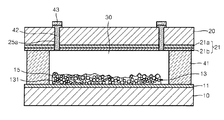
図1は、本発明の一具現例による色素増感型太陽電池の構造を示した断面図である。
図1を参照すると、本実施形態による太陽電池は、第1電極11と、光吸収層13及び染料15とを備える第1基板10;第2電極21を備える第2基板20;が互いに対置され、第1電極11と第2電極21との間に、電解質30が位置して構成される。第1基板10と第2基板20との外側に、別途のケース(図示せず)が配されうる。これについてさらに詳細に説明する。
FIG. 1 is a cross-sectional view showing the structure of a dye-sensitized solar cell according to an embodiment of the present invention.
Referring to FIG. 1, in the solar cell according to the present embodiment, a
本実施形態で、第1電極11を支持する支持体の役割を行う第1基板10は、外部光の入射が可能なように透明に形成される。このために、第1基板10は、ガラスまたはプラスチックからなりうる。プラスチックの具体的な例としては、ポリエチレンテレフタレート(PET)、ポリエチレンナフタレート(PEN)、ポリカーボネート(PC)、ポリプロピレン(PP)、ポリイミド(PI)、トリアセチルセルロース(TAC)などを挙げることができる。
In the present embodiment, the
第1基板10に形成される第1電極11は、ITO、インジウム酸化物、スズ酸化物、亜鉛酸化物、硫黄酸化物、フッ素酸化物、ZnO−Ga2O3、ZnO−Al2O3及びそれら混合物のうちから選択された一つ以上の透明物質からなりうる。第1電極11は、前記透明物質の単一膜または積層膜からなりうる。
The
第1電極11上には、光吸収層13が形成される。かような光吸収層13は、二酸化チタン粒子131を含み、適切な平均気孔サイズを有することによって、電解質30の移動を容易にしつつ、二酸化チタン粒子131のネッキング特性を向上させることができる。
光吸収層13は、10nmないし3,000nm厚、例えば10nmないし1,000nmでありうる。しかし、これに限定されるものではなく、前記厚みは、技術発展などによって変化しうることは言うまでもない。
A
The
前記光吸収層13の表面には、外部光を吸収して励起電子を生成する染料15が吸着される。
A
一方、第1基板10に対置される第2基板20は、第2電極21を支持する支持体の役割を行い、透明に形成されうる。前記第2基板20は、第1基板10のように、ガラスまたはプラスチックからなりうる。
Meanwhile, the
第2基板20に形成される第2電極21は、第1電極11と対置されるように形成され、透明電極21aと触媒電極21bとを含むことができる。
透明電極21aは、ITO、フルオロスズ酸化物、アンチモンスズ酸化物、亜鉛酸化物、スズ酸化物、ZnO−Ga2O3、ZnO−Al2O3などの透明物質からなりうる。このとき、透明電極21aは、前記透明物質の単一膜または積層膜からなりうる。
The
The
前記触媒電極21bは、酸化・還元対(redox couple)を活性化させる役割を行うものであり、触媒電極として、本発明の一態様による白金電極を使用する。
The
前記第1基板10と第2基板20は、接着剤41によって接合され、第2基板20と第2電極21とを貫通するホール25aを介して電解質30が注入され、第1電極11と第2電極21との間に、本発明の一態様による電解質30で満たされる。かような電解質30は、光吸収層13の内部に均一に分散される。電解質30は、酸化還元によって、第2電極21から電子を受け、染料15に伝達する役割を行う。第2基板20及び第2電極21を貫通するホール25aは、接着剤42及びカバーガラス43によって密封される。
図1には示されていないが、前記第1電極11の上部そして前記光吸収層13の下部には、一般的な多孔質膜である金属酸化物膜がさらに形成されうる。
The
Although not shown in FIG. 1, a metal oxide film, which is a general porous film, may be further formed on the
ここで、前記光吸収層13は、光散乱電極の役割と、多量の染料吸着能とを示すことによって、既存の光散乱電極の短所を補完し、色素増感型太陽電池の効率を高めるのである。
Here, the
前記多孔質膜は、金属酸化物粒子から構成されて、二酸化チタン(titanium oxide)、亜鉛酸化物、スズ酸化物、ストロンチウム酸化物(strontium oxide)、インジウム酸化物(indium oxide)、イリジウム酸化物(iridium oxide)、ランタン酸化物(lanthan oxide)、バナジウム酸化物(vanadium oxide)、モリブデン酸化物(molybdenum oxide)、タングステン酸化物(tungsten oxide)、ニオブ酸化物(niobium oxide)、マグネシウム酸化物(magnesium oxide)、アルミニウム酸化物(aluminium oxide)、イットリウム酸化物(yttrium oxide)、スカンジウム酸化物(scandium oxide)、サマリウム酸化物(samarium oxide)、ガリウム酸化物(galluim oxide)、ストロンチウム二酸化チタン(strontium titanium oxide)などからなりうる。ここで、金属酸化物粒子は、一態様によれば、チタン酸化物であるTiO2、スズ酸化物であるSnO2、タングステン酸化物であるWO3、亜鉛酸化物であるZnO、またはそれらの複合体からなりうる。 The porous film is composed of metal oxide particles, such as titanium oxide, zinc oxide, tin oxide, strontium oxide, indium oxide, iridium oxide ( iridium oxide, lanthanum oxide, vanadium oxide, molybdenum oxide (molybdenum oxide), tungsten oxide (tungsten oxide), niobium oxide, magnesium oxide (magnesium oxide) ), Aluminum oxide, yttrium oxide, scandium oxide, samarium oxide, galluim oxide, strontium titanium oxide It can consist of Here, according to one aspect, the metal oxide particles include TiO 2 that is titanium oxide, SnO 2 that is tin oxide, WO 3 that is tungsten oxide, ZnO that is zinc oxide, or a composite thereof. Can consist of body.
以下、本発明の一態様による色素増感型太陽電池の製造方法について説明する。
まず、第1電極に、染料が吸着された多孔質膜を含む光吸収層を形成する。
別途、透明電極と触媒電極とホールとが形成された第2電極を準備し、この第2電極と、前記光吸収層の形成された第1電極とを接合する。
前記第2電極のホールを介して、電解質形成用組成物を注入し、色素増感型太陽電池を製作することができる。
Hereinafter, a method for manufacturing a dye-sensitized solar cell according to one embodiment of the present invention will be described.
First, a light absorption layer including a porous film on which a dye is adsorbed is formed on the first electrode.
Separately, a second electrode in which a transparent electrode, a catalyst electrode, and a hole are formed is prepared, and the second electrode is bonded to the first electrode in which the light absorption layer is formed.
A dye-sensitized solar cell can be manufactured by injecting a composition for forming an electrolyte through the hole of the second electrode.
前記電解質形成用組成物は、高分子ヨウ素錯体、ヨウ化物、高沸点溶媒及び無機ナノ粒子を含有する。前記電解質形成用組成物には、粘度調節用高分子及び窒素含有添加剤のうちから選択された一つ以上をさらに付加することができる。 The composition for forming an electrolyte contains a polymer iodine complex, an iodide, a high boiling point solvent, and inorganic nanoparticles. One or more selected from a viscosity adjusting polymer and a nitrogen-containing additive may be further added to the electrolyte forming composition.
本発明の他の一態様による色素増感型太陽電池は、下記方法によって製作可能である。
まず、第1電極に染料が吸着された多孔質膜を含む光吸収層を形成する。
前記光吸収層上に、高分子ヨウ素錯体、ヨウ化物、高沸点溶媒及び無機ナノ粒子を混合し、電解質形成用組成物を塗布してゲル型電解質を形成する。
前記電解質形成用組成物には、粘度調節用高分子及び窒素含有添加剤のうちから選択された一つ以上をさらに付加することができる。
前記ゲル型電解質の上部に、第2電極を位置させた後、第1電極と第2電極とを接合する段階を経て、色素増感型太陽電池が製造されうる。
The dye-sensitized solar cell according to another embodiment of the present invention can be manufactured by the following method.
First, a light absorption layer including a porous film having a dye adsorbed on the first electrode is formed.
A polymer iodine complex, iodide, a high boiling point solvent, and inorganic nanoparticles are mixed on the light absorption layer, and a composition for forming an electrolyte is applied to form a gel electrolyte.
One or more selected from a viscosity adjusting polymer and a nitrogen-containing additive may be further added to the electrolyte forming composition.
After the second electrode is positioned on the gel electrolyte, a dye-sensitized solar cell may be manufactured through a step of joining the first electrode and the second electrode.
以下、望ましい実施例を挙げて説明するが、本発明がそれらに限定されるものではない。
<実施例1:電解質(PVP−I2+TiO2)の製造>
ポリビニルピロリドン(PVP)−I2錯体(化学式(1)で、n=10、m=80)は、アルドリッチ(Aldrich)から購買し、及び、PVP反復単位とI2とのモル比は、10:1であった。
電解質溶媒としては、N−メチル−2−ピロリドン(NMP)を、精製なしに使用した。
NMPに、1−ブチル−3−メチルイミダゾリウムヨウ化物(BMImI)1.2M、PVP−I2 0.045M(モル/L)及び4−tert−ブチルピリジン(TBP)0.5Mを溶解させた。
得られた混合物にTiO2を添加した後、遠心コンディショニングミキサ(centrifugal conditioning mixer)(Thinky mixer)を利用して混合(2,000rpm/30min)し、ゲル型電解質を製造した。前記TiO2の含有量は、電解質総重量を基準として、約5重量%である。前記TiO2は、平均粒径約20nmであり、使用前に500℃で30分間焼結後に使用した。
Hereinafter, although a desirable example is given and explained, the present invention is not limited to them.
<Example 1: Production of electrolyte (PVP-I 2 + TiO 2 )>
Polyvinylpyrrolidone (PVP) -I 2 complex (formula (1), n = 10, m = 80) was purchased from Aldrich and the molar ratio of PVP repeat units to I 2 was 10: 1
As the electrolyte solvent, N-methyl-2-pyrrolidone (NMP) was used without purification.
In NMP, 1-butyl-3-methylimidazolium iodide (BMImI) 1.2M, PVP-I 2 0.045M (mol / L) and 4-tert-butylpyridine (TBP) 0.5M were dissolved. .
After adding TiO 2 to the obtained mixture, the mixture was mixed (2,000 rpm / 30 min) using a centrifugal conditioning mixer (Thinky mixer) to produce a gel-type electrolyte. The content of TiO 2 is about 5% by weight based on the total weight of the electrolyte. The TiO 2 had an average particle size of about 20 nm and was used after sintering at 500 ° C. for 30 minutes before use.
<実施例2:電解質(PVP−I2+TiO2+PEO)の製造>
TiO2添加時に、酸化ポリエチレン(PEO)(Mw=300,000g/mol)をともに付加することを除いては、実施例1と同じ方法によって実施し、電解質を製造した。
前記PEOの含有量は、電解質総重量を基準として、約9重量%である。
前記PEOの含有量は、無機ナノ粒子(TiO2)100重量部を基準として、180重量部に該当する。
<Example 2: Production of electrolyte (PVP-I 2 + TiO 2 + PEO)>
An electrolyte was produced in the same manner as in Example 1 except that polyethylene oxide (PEO) (Mw = 300,000 g / mol) was added together when TiO 2 was added.
The PEO content is about 9% by weight based on the total weight of the electrolyte.
The content of the PEO corresponds to 180 parts by weight based on 100 parts by weight of inorganic nanoparticles (TiO 2 ).
<比較例1:電解質(I2)の製造>
電解質の製造時、溶媒としては、NMPを精製なしに使用した。I2添加量は、0.12Mに固定した。
NMPに、1−ブチル−3−メチルイミダゾリウムヨウ化物(BMImI)1.2M、I2及び4−tert−ブチルピリジン(TBP)0.5Mを溶解させて電解質を製造した。
<Comparative Example 1: Production of electrolyte (I 2 )>
During the production of the electrolyte, NMP was used as a solvent without purification. The amount of I 2 added was fixed at 0.12M.
An electrolyte was prepared by dissolving 1.2 M of 1-butyl-3-methylimidazolium iodide (BMImI), I 2 and 0.5 M of 4-tert-butylpyridine (TBP) in NMP.
<比較例2:電解質(I2+TiO2)の製造>
比較例1の電解質に、TiO2を、電解質総重量を基準として、約5重量%をさらに付加及び混合し、遠心コンディショニングミキサ(Thinky mixer)を利用して混合(2,000rpm/30min)し、電解質を製造した。
前記TiO2は、粒径約20nmであり、使用前に500℃で30分間焼結した後で使用した。
<Comparative Example 2: Production of electrolyte (I 2 + TiO 2 )>
About 5% by weight of TiO 2 is further added to and mixed with the electrolyte of Comparative Example 1 based on the total weight of the electrolyte, and mixed (2,000 rpm / 30 min) using a centrifugal conditioning mixer (Thinky mixer). An electrolyte was produced.
The TiO 2 had a particle size of about 20 nm and was used after being sintered at 500 ° C. for 30 minutes before use.
<比較例3:電解質(PVP−I2)の製造>
I2の代わりに、PVP−I2を付加したことを除いては、比較例1と同じ方法によって実施し、電解質を製造した。
<Comparative Example 3: Production of electrolyte (PVP-I 2 )>
Instead of I 2, except that the addition of PVP-I 2, performed by the same manner as in Comparative Example 1, to form an electrolyte.
<評価例:評価セルの製造及び評価>
フッ素含有酸化スズ(FTO)基板(厚み:2.3mm)上に、TiO2ペースト(PST−18NR、日本・JGC C&C)を、スクリーン印刷を介して12μm厚に塗布し、500℃/30min条件で焼成し、次に、散乱粒子ペースト(400c、日本・JGC C&C)を同じ方法で印刷/焼成し(焼成後に約4μm)、光負極を製造した。
製造された光負極を、下記式で表される染料(N719)溶液(0.2mM/EtOH)に浸漬させ、24時間放置した。そして、対向電極は、フッ素ドープ酸化スズ(FTO)にPtを20分間スパッタリングして準備した。
On a fluorine-containing tin oxide (FTO) substrate (thickness: 2.3 mm), a TiO 2 paste (PST-18NR, Japan, JGC C & C) was applied to a thickness of 12 μm via screen printing, under conditions of 500 ° C./30 min. Next, the scattering particle paste (400c, Japan, JGC C & C) was printed / fired by the same method (about 4 μm after firing) to produce a photo negative electrode.
The produced photonegative electrode was immersed in a dye (N719) solution (0.2 mM / EtOH) represented by the following formula and left for 24 hours. The counter electrode was prepared by sputtering Pt on fluorine-doped tin oxide (FTO) for 20 minutes.
ホットメルト・フィルム(hot melt film)(Suryln、DuPont、60μm)を、光負極と、ホールが形成された対向電極との間に挿入した後、ホットプレス(hot press)を利用して熱接着(130℃/15sec)した。前記実施例1及び2または比較例1〜3によって製造された電解質を、対向電極に形成されたホールを介して注入した。 A hot melt film (Suryln, DuPont, 60 μm) is inserted between the photo negative electrode and the counter electrode in which holes are formed, and then thermally bonded using a hot press ( 130 ° C./15 sec). The electrolyte manufactured according to Examples 1 and 2 or Comparative Examples 1 to 3 was injected through a hole formed in the counter electrode.
製造されたセルは、標準測定条件(AM1.5G、100mWcm−2)で、電流−電圧曲線を評価した。これ以外にも、インピーダンス分析機(impedance analyzer)を利用してイオン伝導度及びセル・インピーダンス測定を行い、Ag腐食評価(電極抵抗変化測定)を行った。 The manufactured cell was evaluated for a current-voltage curve under standard measurement conditions (AM1.5G, 100 mWcm −2 ). In addition to this, ion conductivity and cell impedance were measured using an impedance analyzer, and Ag corrosion evaluation (electrode resistance change measurement) was performed.
また、前記過程によって製造されたセルの開放電圧、短絡電流密度、エネルギー変換効率及び曲線因子(FF:fill factor)の測定条件は、次の通りである。
(1)開放電圧(VOC)及び短絡電流密度(JSC)
開放電圧と光電流密度は、Keithley SMU2400を利用して測定した。
(2)エネルギー変換効率(R、%)及び曲線因子(%)
エネルギー変換効率の測定は、1.5AM 100mW/cm2のソーラーシミュレータ(solar simulator)(Xeランプ[300W、Oriel]、AM1.5フィルタ及びKeithley SMU2400によって構成)を利用し、曲線因子は、前記で得た変換効率及び下記数式1を利用して計算した。
(1) Open-circuit voltage (V OC ) and short-circuit current density (J SC )
Open circuit voltage and photocurrent density were measured using Keithley SMU2400.
(2) Energy conversion efficiency (R,%) and fill factor (%)
The energy conversion efficiency was measured using a 1.5
前記実施例1による電解質を利用した太陽電池と、比較例1及び比較例3による電解質を利用した太陽電池とを製造し、ソーラーシミュレータを利用して、標準測定条件で電流−電圧特性を評価した。その結果は、下記表1の通りである。下記表1の光電変換特性は、測定条件AM1.5G/100mWcm−2で評価されたものである。
表1から分かるように、実施例1の電解質を用いた太陽電池は、光電変換特性、効率のいずれの点においても、比較例1及び3に比べて、顕著に優れていた。 As can be seen from Table 1, the solar cell using the electrolyte of Example 1 was significantly superior to Comparative Examples 1 and 3 in both photoelectric conversion characteristics and efficiency.
前記表1に示した、実施例1及び比較例1、3によって製造されたゲル型電解質を利用した太陽電池について、ソーラーシミュレータを利用して、標準測定条件で電流−電圧特性を測定し、効率特性結果を図2に示した。 About the solar cell using the gel electrolyte manufactured by Example 1 and Comparative Examples 1 and 3 shown in Table 1, the current-voltage characteristics were measured under standard measurement conditions using a solar simulator, and the efficiency The characteristic results are shown in FIG.
評価した結果、液体電解質に高分子を添加することによって、Vocが大きく増加した。これは、添加されたPEOが光負極のTiO2ナノ粒子の表面を覆い包むことによって、I3 −イオンとの直接的な接触を防止し、従って、電子再結合が減少した結果であると解釈することができる。また、高分子の添加によって、多少低下したJscは、ナノ粒子を電解質に添加することによって、大きく向上するということが分かる。これは、電解質の酸化還元対がナノ粒子によって形成された経路を介して移動することによって、イオン伝導特性が改善された結果であると思料される。 As a result of evaluation, Voc was greatly increased by adding a polymer to the liquid electrolyte. Construed to prevent direct contact with the ion, therefore, is a result of electron recombination is reduced - which, by the added PEO is surround the surface of the TiO 2 nanoparticles of light negative electrode, I 3 can do. It can also be seen that Jsc, which is slightly reduced by the addition of the polymer, is greatly improved by adding the nanoparticles to the electrolyte. This is thought to be the result of improved ion conduction properties due to the redox couple of the electrolyte moving through the path formed by the nanoparticles.
図2を参照しつつ、各電解質別の最適ヨウ素濃度を確認することができる。
図2で実施例1の電解質は、比較例1及び3の場合と比較して、最適性能のために、相対的に低いヨウ素濃度を要求するということが分かる。これは、ナノ粒子添加によって、酸化還元対の移動特性が向上したためである。
With reference to FIG. 2, the optimum iodine concentration for each electrolyte can be confirmed.
It can be seen in FIG. 2 that the electrolyte of Example 1 requires a relatively low iodine concentration for optimal performance as compared to Comparative Examples 1 and 3. This is because the transfer characteristics of the redox couple were improved by the addition of nanoparticles.
前記実施例1、比較例1及び比較例3によって製造された電解質を利用して製造された太陽電池のインピーダンスを測定し、その結果を図3に示した。図3を参照すれば、1sunで測定した結果を見れば、ヨウ素濃度が上昇するほど、低周波数領域での電解質拡散抵抗が大きく低下するということが分かる。また、図3から分かるように、実施例1の電解質は、比較例1及び比較例3の場合と比較して、電解質拡散抵抗が小さい。 The impedance of the solar cell manufactured using the electrolyte manufactured in Example 1, Comparative Example 1 and Comparative Example 3 was measured, and the result is shown in FIG. Referring to FIG. 3, it can be seen from the measurement result at 1 sun that the electrolyte diffusion resistance in the low frequency region greatly decreases as the iodine concentration increases. As can be seen from FIG. 3, the electrolyte of Example 1 has a smaller electrolyte diffusion resistance than those of Comparative Examples 1 and 3.
前記実施例1及び比較例3によって製造された電解質において、インピーダンス及び伝導度特性を調べて、下記表2に示した。
前記表2を参照すれば、電解質にTiO2ナノ充填剤を添加した場合、約2倍のイオン伝導度の向上を確認することができた。 Referring to Table 2, when the TiO 2 nanofiller was added to the electrolyte, it was confirmed that the ion conductivity was improved about twice.
また、実施例1及び比較例2による電解質で、Agグリッド腐食速度を測定するために、Agグリッドセルに前記電解質を注入し、85℃で200時間抵抗変化測定を行い、その結果を図4に示した。図4から分かるように、実施例1の電解質は、比較例2の電解質に比べて、顕著に低い抵抗を示した。 In addition, in order to measure the Ag grid corrosion rate with the electrolytes of Example 1 and Comparative Example 2, the electrolyte was injected into the Ag grid cell, the resistance change measurement was performed at 85 ° C. for 200 hours, and the result is shown in FIG. Indicated. As can be seen from FIG. 4, the electrolyte of Example 1 showed a significantly lower resistance than the electrolyte of Comparative Example 2.
以上、本発明の望ましい製造例を参照しつつ説明したが、当該技術分野の当業者であるならば、特許請求の範囲に記載された本発明の思想及び領域から外れない範囲内で、本発明を多様に修正及び変更させることができるということを理解することができるであろう。 Although the present invention has been described with reference to the preferred production examples of the present invention, those skilled in the art will recognize that the present invention is within the scope and spirit of the present invention described in the claims. It will be understood that various modifications and changes can be made.
10 第1基板
11 第1電極
13 光吸収層
131 金属酸化物粒子
15 染料
20 第2基板
21 第2電極
21a 透明電極
21b 触媒電極
25a ホール
30 電解質
41,42 接着剤
43 カバーガラス
DESCRIPTION OF
Claims (18)
無機ナノ粒子と、
高沸点有機溶媒と、を含む色素増感型太陽電池用ゲル型電解質。 A redox couple generated from a polymeric iodine complex and iodide;
Inorganic nanoparticles,
A gel-type electrolyte for a dye-sensitized solar cell, comprising a high-boiling organic solvent.
ポリビニルアルコール、ポリビニルピロリドン、ポリビニルピリジン、ポリアミド及び多糖類からなる群から選択された一つ以上であることを特徴とする請求項1に記載の色素増感型太陽電池用ゲル型電解質。 The polymer of the iodine complex is
The gel electrolyte for a dye-sensitized solar cell according to claim 1, wherein the gel electrolyte is one or more selected from the group consisting of polyvinyl alcohol, polyvinyl pyrrolidone, polyvinyl pyridine, polyamide, and polysaccharide.
下記化学式(1)で表示されることを特徴とする請求項1又は2に記載の色素増感型太陽電池用ゲル型電解質:
The gel type electrolyte for dye-sensitized solar cell according to claim 1 or 2, which is represented by the following chemical formula (1):
チタニア、シリカ及び酸化インジウムスズからなる群から選択された一つ以上であることを特徴とする請求項1〜3のいずれか1項に記載の色素増感型太陽電池用ゲル型電解質。 The inorganic nanoparticles are
The gel electrolyte for a dye-sensitized solar cell according to any one of claims 1 to 3, wherein the gel electrolyte is one or more selected from the group consisting of titania, silica and indium tin oxide.
沸点が120℃以上である有機溶媒であることを特徴とする請求項1〜4のいずれか1項に記載の色素増感型太陽電池用ゲル型電解質。 The high boiling point organic solvent is
The gel electrolyte for a dye-sensitized solar cell according to any one of claims 1 to 4, wherein the gel electrolyte is an organic solvent having a boiling point of 120 ° C or higher.
3−メトキシプロピオンニトリル、N−メチルピロリドン(NMP)、1−アルキル(R)−3−メチルイミダゾリウムテトラシアノボレート、1−アルキル(R)−3−メチルイミダゾリウムジシアンアミド、1−アルキル(R)−3−メチルイミダゾリウムビス(トリフルオロメチルスルホニル)イミドからなる群から選択された一つ以上であり、
前記アルキル(R)は、C1−C20アルキル基またはC2−C20アルケニル基であることを特徴とする請求項1〜5のいずれか1項に記載の色素増感型太陽電池用ゲル型電解質。 The high boiling point organic solvent is
3-methoxypropiononitrile, N-methylpyrrolidone (NMP), 1-alkyl (R) -3-methylimidazolium tetracyanoborate, 1-alkyl (R) -3-methylimidazolium dicyanamide, 1-alkyl ( One or more selected from the group consisting of R) -3-methylimidazolium bis (trifluoromethylsulfonyl) imide;
Wherein alkyl (R) is, C 1 -C 20 alkyl or C 2 -C 20 for dye-sensitized solar cell gel according to claim 1, characterized in that the alkenyl group Type electrolyte.
高分子ヨウ素錯体の陽イオンと、ヨウ素イオン(I−及び/又はI3 −)とを含むことを特徴とする請求項1〜8のいずれか1項に記載の色素増感型太陽電池用ゲル型電解質。 The redox couple generated from the polymeric iodine complex and iodide is
And cationic polymer iodine complex, an iodine ion (I - and / or I 3 -) and the gel for dye-sensitized solar cell according to any one of claims 1-8, characterized in that it comprises Type electrolyte.
ナノ無機粒子100重量部を基準として、40ないし400重量部であることを特徴とする請求項1〜9のいずれか1項に記載の色素増感型太陽電池用ゲル型電解質。 The content of the redox couple is
The gel electrolyte for a dye-sensitized solar cell according to any one of claims 1 to 9, wherein the amount is 40 to 400 parts by weight based on 100 parts by weight of the nano-inorganic particles.
ナノ無機粒子100重量部を基準として、1,000ないし1,600重量部であることを特徴とする請求項1〜10のいずれか1項に記載の色素増感型太陽電池用ゲル型電解質。 The content of the high boiling point solvent is
The gel electrolyte for a dye-sensitized solar cell according to any one of claims 1 to 10, wherein the amount is 1,000 to 1,600 parts by weight based on 100 parts by weight of the nano-inorganic particles.
ナノ無機粒子100重量部を基準として、20ないし200重量部であることを特徴とする請求項7〜11のいずれか1項に記載の色素増感型太陽電池用ゲル型電解質。 The content of the viscosity adjusting polymer is
The gel electrolyte for a dye-sensitized solar cell according to any one of claims 7 to 11, wherein the gel electrolyte is 20 to 200 parts by weight based on 100 parts by weight of the nano-inorganic particles.
酸化エチレン系高分子、フッ化ビニリデン−ヘキサフルオロプロピレン共重合体からなる群から選択された一つ以上であることを特徴とする請求項7〜12のいずれか1項に記載の色素増感型太陽電池用ゲル型電解質。 The viscosity adjusting polymer is
The dye-sensitized dye according to any one of claims 7 to 12, wherein the dye-sensitized dye is one or more selected from the group consisting of an ethylene oxide polymer and a vinylidene fluoride-hexafluoropropylene copolymer. Gel electrolyte for solar cells.
ヨウ化リチウム(LiI)、ヨウ化ブロム(LiBr)、ヨウ化ナトリウム、ヨウ化カリウム、ヨウ化マグネシウム、ヨウ化銅、ヨウ化ケイ素、ヨウ化マンガン、ヨウ化バリウム、ヨウ化モリブデン、ヨウ化カルシウム、ヨウ化鉄、ヨウ化セシウム、ヨウ化亜鉛、ヨウ化水銀、ヨウ化アンモニウム、ヨウ化メチル、ヨウ化メチレン、ヨウ化エチル、ヨウ化エチレン、ヨウ化イソプロピル、ヨウ化イソブチル、ヨウ化ベンジル、ヨウ化ベンゾイル、ヨウ化アリル、ヨウ化イミダゾリウム、ヨウ化ピリジニウム及びヨウ化ピロリジウムからなる群から選択された一つ以上であることを特徴とする請求項1〜14のいずれか1項に記載の色素増感型太陽電池用ゲル型電解質。 The iodide is
Lithium iodide (LiI), bromide iodide (LiBr), sodium iodide, potassium iodide, magnesium iodide, copper iodide, silicon iodide, manganese iodide, barium iodide, molybdenum iodide, calcium iodide, Iron iodide, cesium iodide, zinc iodide, mercury iodide, ammonium iodide, methyl iodide, methylene iodide, ethyl iodide, ethylene iodide, isopropyl iodide, isobutyl iodide, benzyl iodide, iodide The dye enhancement according to any one of claims 1 to 14, wherein the dye enhancement is one or more selected from the group consisting of benzoyl, allyl iodide, imidazolium iodide, pyridinium iodide and pyrrolidinium iodide. Gel-type electrolyte for sensitive solar cells.
無機ナノ粒子100重量部を基準として、100ないし300重量部であることを特徴とする請求項16に記載の色素増感型太陽電池用ゲル型電解質。 The content of the nitrogen-containing additive is
The gel-type electrolyte for a dye-sensitized solar cell according to claim 16, wherein the amount is 100 to 300 parts by weight based on 100 parts by weight of the inorganic nanoparticles.
Applications Claiming Priority (2)
| Application Number | Priority Date | Filing Date | Title |
|---|---|---|---|
| KR1020100117096A KR101137379B1 (en) | 2010-11-23 | 2010-11-23 | Gel electrolyte for dye sensitized fuel cell and dye sensitized fuel cell including the same |
| KR10-2010-0117096 | 2010-11-23 |
Publications (1)
| Publication Number | Publication Date |
|---|---|
| JP2012114086A true JP2012114086A (en) | 2012-06-14 |
Family
ID=44651488
Family Applications (1)
| Application Number | Title | Priority Date | Filing Date |
|---|---|---|---|
| JP2011247097A Pending JP2012114086A (en) | 2010-11-23 | 2011-11-11 | Gel electrolyte for dye-sensitized solar cell, and dye-sensitized solar cell including the same |
Country Status (5)
| Country | Link |
|---|---|
| US (1) | US20120125422A1 (en) |
| EP (1) | EP2455955A3 (en) |
| JP (1) | JP2012114086A (en) |
| KR (1) | KR101137379B1 (en) |
| CN (1) | CN102479617A (en) |
Cited By (2)
| Publication number | Priority date | Publication date | Assignee | Title |
|---|---|---|---|---|
| JP2014010997A (en) * | 2012-06-29 | 2014-01-20 | Fujikura Ltd | Electrolyte for electrochemical element, and dye-sensitized solar cell including the same |
| JP2014529895A (en) * | 2011-08-25 | 2014-11-13 | メルク パテント ゲゼルシャフト ミット ベシュレンクテル ハフツングMerck Patent Gesellschaft mit beschraenkter Haftung | Additives for dye-sensitized solar cells |
Families Citing this family (7)
| Publication number | Priority date | Publication date | Assignee | Title |
|---|---|---|---|---|
| US20160217936A1 (en) * | 2012-12-14 | 2016-07-28 | Sharp Kabushiki Kaisha | Photoelectric conversion element |
| TWI505532B (en) * | 2012-12-24 | 2015-10-21 | Eternal Materials Co Ltd | Electrolyte composition for dye-sensitized solar cell |
| JPWO2016017776A1 (en) * | 2014-07-30 | 2017-06-01 | 積水化学工業株式会社 | Manufacturing method of solar cell |
| JP7012660B2 (en) | 2016-04-01 | 2022-02-14 | ノームズ テクノロジーズ インコーポレイテッド | Phosphorus-containing modified ionic liquid |
| JP2018107177A (en) * | 2016-12-22 | 2018-07-05 | 太陽誘電株式会社 | Photoelectric conversion element and electronic component having the same |
| JP7296893B2 (en) | 2017-07-17 | 2023-06-23 | ノームズ テクノロジーズ インコーポレイテッド | Phosphorus-containing electrolyte |
| CN108335912A (en) * | 2018-01-30 | 2018-07-27 | 浙江夏远信息技术有限公司 | A kind of dye-sensitized solar cells quasi-solid electrolyte |
Family Cites Families (6)
| Publication number | Priority date | Publication date | Assignee | Title |
|---|---|---|---|---|
| JP4754862B2 (en) * | 2005-04-15 | 2011-08-24 | シャープ株式会社 | Dye-sensitized solar cell and method for producing the same |
| JP5096700B2 (en) * | 2006-06-27 | 2012-12-12 | パナソニック株式会社 | Photoelectric conversion element |
| KR100869802B1 (en) * | 2006-11-17 | 2008-11-21 | 삼성에스디아이 주식회사 | Electrolyte composition for dye-sensitized solar cell, and dye-sensitized solar cell comprising same and method of preparing same |
| KR20090076410A (en) * | 2008-01-08 | 2009-07-13 | 삼성에스디아이 주식회사 | Gel type electrolyte for dye sensitized solar cell, preparing method for the same and solar cell employing the gel type electrolyte |
| KR101461522B1 (en) * | 2008-04-10 | 2014-11-14 | 한양대학교 산학협력단 | Gel electrolyte and Dye sensitized solar cell using the same |
| JP2010009831A (en) * | 2008-06-25 | 2010-01-14 | Tdk Corp | Photoelectric conversion element |
-
2010
- 2010-11-23 KR KR1020100117096A patent/KR101137379B1/en not_active IP Right Cessation
-
2011
- 2011-04-12 US US13/085,380 patent/US20120125422A1/en not_active Abandoned
- 2011-09-13 CN CN201110276419.6A patent/CN102479617A/en active Pending
- 2011-09-21 EP EP11182215A patent/EP2455955A3/en not_active Withdrawn
- 2011-11-11 JP JP2011247097A patent/JP2012114086A/en active Pending
Cited By (2)
| Publication number | Priority date | Publication date | Assignee | Title |
|---|---|---|---|---|
| JP2014529895A (en) * | 2011-08-25 | 2014-11-13 | メルク パテント ゲゼルシャフト ミット ベシュレンクテル ハフツングMerck Patent Gesellschaft mit beschraenkter Haftung | Additives for dye-sensitized solar cells |
| JP2014010997A (en) * | 2012-06-29 | 2014-01-20 | Fujikura Ltd | Electrolyte for electrochemical element, and dye-sensitized solar cell including the same |
Also Published As
| Publication number | Publication date |
|---|---|
| CN102479617A (en) | 2012-05-30 |
| US20120125422A1 (en) | 2012-05-24 |
| EP2455955A3 (en) | 2012-09-12 |
| KR101137379B1 (en) | 2012-04-20 |
| EP2455955A2 (en) | 2012-05-23 |
Similar Documents
| Publication | Publication Date | Title |
|---|---|---|
| JP2012114086A (en) | Gel electrolyte for dye-sensitized solar cell, and dye-sensitized solar cell including the same | |
| US6900382B2 (en) | Gel electrolytes for dye sensitized solar cells | |
| US7414188B2 (en) | Co-sensitizers for dye sensitized solar cells | |
| US6858158B2 (en) | Low temperature interconnection of nanoparticles | |
| JP4391447B2 (en) | Electrolyte composition and solar cell using the same | |
| KR101381873B1 (en) | Polymer gel electrolyte composition, the preparing method for the composition, and dye-sensitized solar cell comprising the electrolyte | |
| KR101223736B1 (en) | Electrolyte for dye sensitized solar cell and dye sensitized solar cell using the same | |
| CN103429662B (en) | A kind of polymer electrolyte composition and the dye sensitization solar battery containing described composition | |
| JP2007317446A (en) | Dye-sensitized solar cell | |
| JP2006286203A (en) | Raw material kit for electrolyte composition, electrolyte composition and photosensitized solar cell | |
| Bharwal et al. | Remarkable 8.3% efficiency and extended electron lifetime towards highly stable semi-transparent iodine-free DSSCs by mitigating the in-situ triiodide generation | |
| JP5006573B2 (en) | Dye-sensitized solar cell | |
| Balanay et al. | The photovoltaic performances of PVdF-HFP electrospun membranes employed quasi-solid-state dye sensitized solar cells | |
| JP2004241378A (en) | Dye sensitized solar cell | |
| KR101223734B1 (en) | Electrolyte for Dye sensitized solar cell and Dye sensitized solar cell including the same | |
| JP2003257506A (en) | Electrolyte composition, photoelectric transducer and photoelectric cell | |
| JP2008010189A (en) | Photoelectric conversion element | |
| KR101054470B1 (en) | Dye-sensitized solar cell electrolyte and dye-sensitized solar cell using same | |
| JP4050535B2 (en) | Method for producing dye-sensitized solar cell | |
| KR20140112141A (en) | Electrolyte for dye sensitized solar cell and Dye sensitized solar cell using the same | |
| JP2011165615A (en) | Photoelectric conversion element and method of manufacturing the same | |
| KR101135475B1 (en) | Electrolyte composition for photoelectric conversion device and photoelectric conversion device manufactured by using the same | |
| Shahbaz et al. | A poly (styrene-co-acrylonitrile) gel electrolyte for dye-sensitized solar cells with improved photoelectrochemical performance | |
| Kim et al. | Effect of TiO~ 2 Inclusion in the Poly (vinylidene fluoride-co-hexafluoropropylene)-Based Polymer Electrolyte of Dye-Sensitized Solar Cell | |
| KR102294924B1 (en) | Electrolyte having high transmittance and high stability and sensitized solar cell comprising the same |