JP2012113419A - Touch type input device - Google Patents
Touch type input device Download PDFInfo
- Publication number
- JP2012113419A JP2012113419A JP2010260250A JP2010260250A JP2012113419A JP 2012113419 A JP2012113419 A JP 2012113419A JP 2010260250 A JP2010260250 A JP 2010260250A JP 2010260250 A JP2010260250 A JP 2010260250A JP 2012113419 A JP2012113419 A JP 2012113419A
- Authority
- JP
- Japan
- Prior art keywords
- touch
- vibration
- display panel
- panel
- input device
- Prior art date
- Legal status (The legal status is an assumption and is not a legal conclusion. Google has not performed a legal analysis and makes no representation as to the accuracy of the status listed.)
- Pending
Links
Images


Abstract
Description
本発明は、タッチ式入力装置に係り、特に、操作パネル自体を振動させることで、タッチ操作入力の受け付けを操作者に認識させるタッチ式入力装置に関する。 The present invention relates to a touch input device, and more particularly, to a touch input device that allows an operator to recognize acceptance of a touch operation input by vibrating an operation panel itself.
車両の運転席の中央部付近に配置されたセンタークラスタには、例えば画像ディスプレイ装置、エアコン装置、カーナビゲーション装置やオーディオ装置等の各種の車載機器を操作するためのタッチ式入力装置が設けられている。このタッチ式入力装置の操作パネルは、小さい操作力で操作入力することはできるが、プッシュ式のスイッチと比較すると、操作者が受ける操作感触が小さい。このため、操作者は、タッチ操作入力がなされたか否かを画像ディスプレイ装置に表示されたアイコン等の変化で確認する必要があり、特に、車両の運転中のブラインドタッチ操作ができなかった。 The center cluster arranged near the center of the driver's seat of the vehicle is provided with a touch input device for operating various in-vehicle devices such as an image display device, an air conditioner device, a car navigation device and an audio device. Yes. Although the operation panel of the touch input device can input an operation with a small operation force, the operation feeling received by the operator is smaller than that of a push switch. For this reason, the operator needs to confirm whether or not a touch operation input has been made by a change in an icon or the like displayed on the image display device, and in particular, a blind touch operation during driving of the vehicle has not been possible.
そこで、タッチ式入力装置の操作パネルに対してタッチ操作入力がなされたときに十分な操作感触が得られるように、操作入力の受け付けを振動で提示するタッチ式入力装置が提案されている(例えば、特許文献1参照)。 In view of this, a touch input device has been proposed that presents the acceptance of an operation input by vibration so that a sufficient operation feel can be obtained when a touch operation input is made on the operation panel of the touch input device (for example, , See Patent Document 1).
上記特許文献1に記載されたタッチ式入力装置は、スイッチ箱内に弾性変形可能な弾性支持手段を介して位置変位可能に支持された第1電極体(第1タッチ操作面)と、スイッチ箱の蓋機能を有する第2電極体(第2タッチ操作面)との両方にタッチすることで、第1タッチ操作面に振動を付与する構成となっている。 The touch-type input device described in Patent Document 1 includes a first electrode body (first touch operation surface) supported in a switch box so as to be displaceable via elastic support means that can be elastically deformed, and a switch box. By touching both of the second electrode body (second touch operation surface) having a lid function, vibration is applied to the first touch operation surface.
上記特許文献1記載のタッチ式入力装置は、弾性変形可能な弾性支持手段を必要とするため、タッチ式の操作パネルとしては部品点数が多過ぎる。一方、第1タッチ操作面が受ける振動によって、第1タッチ操作面と第2タッチ操作面の距離が変化することから、第1タッチ操作面及び第2タッチ操作面間の隙間を大きく設定する必要がある。この隙間が形成されていると、タッチ式入力装置の外観上の見栄えが乏しくなる。 The touch-type input device described in Patent Document 1 requires elastic support means that can be elastically deformed, and therefore has too many components as a touch-type operation panel. On the other hand, since the distance between the first touch operation surface and the second touch operation surface changes due to vibration received by the first touch operation surface, it is necessary to set a large gap between the first touch operation surface and the second touch operation surface. There is. If this gap is formed, the appearance of the touch input device will be poor.
本発明の目的は、構造が簡単であり、外観の見栄えや意匠性を向上させたタッチ式入力装置を提供することにある。 An object of the present invention is to provide a touch input device having a simple structure and improved appearance and design.
[1]本発明は、上記目的を達成するため、周囲が固定され、タッチセンサを有する操作パネルと、前記操作パネルのn次(nは自然数)の振動モードを発生する位置に配置された振動アクチュエータとを備えたことを特徴とするタッチ式入力装置が提供される。 [1] In order to achieve the above object, according to the present invention, an operation panel having a fixed periphery and having a touch sensor, and a vibration arranged at a position where an n-th vibration mode (n is a natural number) of the operation panel is generated. There is provided a touch-type input device including an actuator.
[2]上記[1]記載の前記操作パネルは、前記n次の振動モードの固有振動数で加振されることを特徴とする。 [2] The operation panel according to [1] is characterized in that the operation panel is vibrated at a natural frequency of the n-th vibration mode.
[3]上記[1]又は[2]記載の前記振動アクチュエータを駆動する信号は、振幅変調した信号であることを特徴とする。 [3] The signal for driving the vibration actuator according to [1] or [2] is an amplitude-modulated signal.
[4]上記[1]〜[3]のいずれかに記載のタッチ式入力装置は、前記操作パネルに対応する基板を備え、前記操作パネルと前記基板との間に空間を形成するように、前記操作パネルが前記基板に固定されたことを特徴とする。 [4] The touch input device according to any one of [1] to [3] includes a substrate corresponding to the operation panel, and a space is formed between the operation panel and the substrate. The operation panel is fixed to the substrate.
本発明によれば、組立部品点数が少なく、構造が簡単であり、外観の見栄えや意匠性を向上させたタッチ式入力装置が得られる。 According to the present invention, it is possible to obtain a touch input device having a small number of assembly parts, a simple structure, and improved appearance and design.
以下、本発明の好適な実施の形態を添付図面に基づいて具体的に説明する。 Preferred embodiments of the present invention will be specifically described below with reference to the accompanying drawings.
[第1の実施の形態]
(車両の前部座席前方の全体構成)
図1において、車両1の前部座席の前方には、計器類や助手席用エアバッグなどが装着された合成樹脂製のインストルメントパネル2が車幅方向に配置されている。このインストルメントパネル2の車両右側部位には、ステアリングホイール3が図示しないステアリングコラムを介して車体に組み付けられている。このインストルメントパネル2の中央部付近にはセンタークラスタ4が配置されている。このセンタークラスタ4の意匠面側には各種の選択画面を表示可能な画像ディスプレイ装置5が設けられている。
[First Embodiment]
(Overall configuration in front of the front seat of the vehicle)
In FIG. 1, in front of a front seat of a vehicle 1, an instrument panel 2 made of a synthetic resin and equipped with instruments and a passenger seat airbag is arranged in the vehicle width direction. A
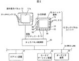
このセンタークラスタ4と画像ディスプレイ装置5との間に形成された部位には、図1及び図2に示すように、各種の車載機器を作動させるタッチ式入力装置であるタッチパネルユニット10が設けられている。このタッチパネルユニット10の操作対称となる車載機器は、車両1の室内に設置された操作対象機器である。この操作対象機器の一例としては、例えばエアコン装置31、カーナビゲーション装置32やオーディオ装置33などがある(以下、「操作対称機器31〜33」ともいう。)。
As shown in FIG. 1 and FIG. 2, a touch panel unit 10 that is a touch input device for operating various vehicle-mounted devices is provided in a portion formed between the center cluster 4 and the image display device 5. Yes. The in-vehicle device that is symmetrical to the operation of the touch panel unit 10 is an operation target device installed in the room of the vehicle 1. Examples of the operation target device include an
(タッチパネルユニットの構成)
このタッチパネルユニット10は、図2に示すように、複数のタッチセンサ12を配した操作表示パネル11と、操作表示パネル11の裏面に対向して配置されるユニット基板13と、タッチパネルユニット10を制御するタッチパネル制御部20とにより主に構成されている。
(Configuration of touch panel unit)
As shown in FIG. 2, the touch panel unit 10 controls an operation display panel 11 provided with a plurality of
この操作表示パネル11は、例えばアクリル系樹脂あるいはポリカーボネート系樹脂等の透明樹脂材料からなり、四角枠板状に形成されている。この操作表示パネル11の中央部には、図2に示すように、画像ディスプレイ装置5を嵌め込むための開口部11aが形成されている。 The operation display panel 11 is made of a transparent resin material such as an acrylic resin or a polycarbonate resin, and is formed in a square frame plate shape. As shown in FIG. 2, an opening 11 a for fitting the image display device 5 is formed at the center of the operation display panel 11.
操作表示パネル11の裏面又は表面には、例えば表示形状に対応した部分を除いてシルク印刷を施した遮光性の印刷層が形成されている。この印刷層には、印刷が施されていないタッチ操作面となる光透過牲の抜き表示部が形成されている。その抜き表示部は、操作対称機器31〜33等の文字、数字、図形、記号あるいは絵柄などからなる。なお、タッチ操作面をより視認し易くするために、タッチ操作面に蛍光剤等を塗布する場合もある。
On the back surface or the front surface of the operation display panel 11, for example, a light-shielding printing layer is formed by performing silk printing except for a portion corresponding to the display shape. The printed layer is formed with a light-transmitting removal display portion serving as a touch operation surface that is not printed. The extracted display part is composed of characters, numbers, figures, symbols, or patterns of the operation
この操作表示パネル11のタッチ操作面と対応する裏面には、図2に示すように、タッチ式のスイッチ操作部を構成する複数のタッチセンサ12が配置されている。このタッチセンサ12は、静電容量式のタッチセンサからなり、操作者の手指の接近又は接触を検出する静電容量検出用の透明電極が印刷された透明なフィルムシートにより形成されている。その透明電極は、例えば可視光に対して透明なITO(インジウム錫酸化物)などの金属酸化物の薄膜によりパターン状に形成されている。なお、操作表示パネル11の内部にタッチセンサ12を配置する場合もある。
On the back surface corresponding to the touch operation surface of the operation display panel 11, as shown in FIG. 2, a plurality of
このユニット基板13は、図2に示すように、操作表示パネル11と同一形状の四角枠板状に形成されている。ユニット基板13には、複数のタッチセンサ12のそれぞれに対応して複数の発光ダイオード14(以下、「LED14」という。)が実装されている。このLED14は、操作表示パネル11のタッチセンサ12を背面照射する光源とされており、タッチセンサ12の背後から照明することで、タッチ操作面の視認性を向上させるとともに、視覚的な演出効果を高めている。
As shown in FIG. 2, the unit substrate 13 is formed in a square frame plate shape having the same shape as the operation display panel 11. On the unit substrate 13, a plurality of light emitting diodes 14 (hereinafter referred to as “
このLED14が点灯又は点滅することで、タッチセンサ12の操作対称機器31〜33の操作入力が可能であるか否かなどの状態を操作者に視覚的に認識させることもできる。操作者は、操作表示パネル11に表示される複数のタッチ操作面をタッチセンサ12で選択指定することで、そのタッチ操作面に対応する機能項目を画像ディスプレイ装置5の画面に表示させたり、タッチ操作面に対応する操作対称機器31〜33に所望の動作を実行させたりすることができる。
By turning on or blinking the
一方、操作者がタッチセンサ12をタッチ操作しない場合は、操作表示パネル11のタッチ操作面が消えたブラックアウトのままの状態が続く操作待機状態(LED消灯時)とすることもできる。これにより、操作者は、ブラックアウトされた機能していない操作対称機器31〜33に対する操作を選択肢から除外することができる。
On the other hand, when the operator does not perform a touch operation on the
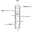
この第1の実施の形態における基本の構成は、タッチセンサ12にタッチした際にフィードバックを得るため、操作表示パネル11自体を振動パネルとして利用することにある。ユニット基板13の操作表示パネル対向面には、図2及び図3に示すように、操作表示パネル11を固定支持する円柱状の固定支持部15と操作表示パネル11を振動させる振動アクチュエータ16とが立設されている。この操作表示パネル11は、ユニット基板13よりも剛性を小さく設定されており、固定支持部15を介してユニット基板13に固定支持されている。
The basic configuration of the first embodiment is to use the operation display panel 11 itself as a vibration panel in order to obtain feedback when the
この固定支持部15は、特に限定されるものではないが、図2及び図3に示すように、ユニット基板13の四角枠板の4つの隅角部に配されており、操作表示パネル11を一定の距離だけ離間させる高さを有している。操作表示パネル11とユニット基板13とを固定支持部15を介して固定することで、操作表示パネル11とユニット基板13との対向面間には空間17が形成される。
Although this fixed
この操作表示パネル11の固定支持構造としては、例えば操作表示パネル11の裏面側の周面部、すなわち裏面側の周囲の一部又は全部が固定端となり、操作表示パネル11が固定梁構造により拘束される形態、あるいは操作表示パネル11の四角枠板外周部が固定梁構造により拘束される形態などを採用することができる。この固定支持部15の形状としては、図示例による円柱体に代えて、ナイフエッジ状に形成されていてもよく、各種の固定支持形状を採用することができる。
As the fixed support structure of the operation display panel 11, for example, a peripheral surface portion on the back surface side of the operation display panel 11, that is, a part or all of the periphery on the back surface side becomes a fixed end, and the operation display panel 11 is restrained by a fixed beam structure. Or a form in which the outer periphery of the square frame plate of the operation display panel 11 is restrained by a fixed beam structure. The shape of the fixed
操作表示パネル11の外周部は、操作表示パネル11の固定支持構造に応じて、接着剤や両面粘着テープなどによる粘着、ネジ止め、又は薄肉ヒンジなどの各種の固定手段を採用することができる。操作表示パネル11の外周部を薄肉ヒンジにより固定する場合は、その薄肉部分が操作表示パネル11と一緒に振動するため、振動するスパン長が長くなり、振動モードの次数を高くすることができる。 Various fixing means such as adhesion using an adhesive or a double-sided adhesive tape, screwing, or a thin hinge can be adopted for the outer peripheral portion of the operation display panel 11 according to the fixing support structure of the operation display panel 11. When the outer peripheral part of the operation display panel 11 is fixed by a thin hinge, the thin part vibrates together with the operation display panel 11, so that the span length to vibrate becomes long and the order of the vibration mode can be increased.
一方、振動アクチュエータ16は、例えばソレノイドからなり、先端の振動子が操作表示パネル11におけるn次(nは自然数)の振動モードの振動形状に合わせて、操作表示パネル11の四角枠板における振動モードの節部分以外となる位置に接合されている。この振動アクチュエータ16は、タッチパネル制御部20で与えられる所定のn次振動モードで操作表示パネル11を加振する。
On the other hand, the
このタッチパネルユニット10を設計するにあたり、定法に従い、例えば操作表示パネル11の複数箇所を加振して、その複数点の振動検出手段の出力をFFT(Fast Fourier Transform)アナライザに入力して解析することで、操作表示パネル11のn次振動モード(例えば、固有周波数や振幅ゲイン)を知ることができる。所定の周波数領域において、操作表示パネル11の全体がどのような挙動で振動するのかを把握することで、操作表示パネル11の目標とする振動モードを実現するための諸元が得られる。 In designing the touch panel unit 10, according to a standard method, for example, a plurality of portions of the operation display panel 11 are vibrated and the outputs of the vibration detection means at the plurality of points are input to an FFT (Fast Fourier Transform) analyzer and analyzed. Thus, the nth-order vibration mode (for example, natural frequency or amplitude gain) of the operation display panel 11 can be known. By grasping how the entire operation display panel 11 vibrates in a predetermined frequency region, specifications for realizing a target vibration mode of the operation display panel 11 can be obtained.
この諸元を得ることにより、操作表示パネル11の振動が所定のn次振動モードを含むように、操作表示パネル11の断面形状、板厚などを含む構造的な諸元を設定することができる。振動アクチュエータ16の配置位置にあっても、操作表示パネル11の全体がどのような挙動で振動するのかを把握することで設定することができる。
By obtaining these specifications, it is possible to set structural specifications including the cross-sectional shape and thickness of the operation display panel 11 so that the vibration of the operation display panel 11 includes a predetermined n-order vibration mode. . Even when the
図3において、操作表示パネル11を加振する前の状態が断面で示されており、図4において、図3に示す操作表示パネル11のモード変形の一断面を示している。図4に示す3次モードの振動においては、振幅の大きな腹部分(可動部分)と、振幅の小さい節部分(不動部分)とが存在する。操作表示パネル11の振幅の節部分となる部位を支持部材18により支持することで、振動損失を少なく設定し、3次モードの振動を発生し易くすることもできる。
In FIG. 3, the state before the operation display panel 11 is vibrated is shown in section, and in FIG. 4, one section of mode deformation of the operation display panel 11 shown in FIG. 3 is shown. In the vibration of the third-order mode shown in FIG. 4, there are an abdominal part (movable part) having a large amplitude and a node part (non-moving part) having a small amplitude. By supporting the part of the operation display panel 11 that becomes the node of the amplitude by the
(タッチパネル制御部の構成)
このタッチパネル制御部20には、図2に示すように、車内LAN34を介してエアコン装置31、カーナビゲーション装置32及びオーディオ装置33が通信可能に接続されている。タッチパネル制御部20は、CPU(Central Processing Unit)、RAM(Random Access Memory)、ROM(Read Only Memory)、信号入出力部等を備えてなるマイクロコンピュータと、車内LANインターフェースや振動アクチュエータ16の駆動部等を実装してユニット化した電子制御手段として構成される。
(Configuration of touch panel controller)
As shown in FIG. 2, an
このタッチパネル制御部20のCPUは、ROMに記憶された所定のプログラムに従って演算処理を行う。タッチパネル制御部20は、タッチセンサ12を構成する電極の静電容量変化を検出したとき、タッチセンサ12がタッチ操作入力されたと判断し、対応する操作対象機器31〜33に操作入力受付信号を送信する。LED14の点灯及び消灯の制御を行うことで、対応する操作対象機器31〜33の状態等を表示制御する。
The CPU of the touch
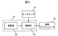
この振動アクチュエータ16の駆動パターンは、例えば電圧波形の周波数及び振幅で決まる。この電圧波形の周波数及び振幅は、図5に示すように、振動アクチュエータ16の駆動信号を生成する駆動信号生成部21によって設定される。
The drive pattern of the
この駆動信号生成部21は、図5に示すように、発振部22及び駆動部23により主に構成される。この発振部22は、所定の振動モードを有する駆動信号(例えば、振幅及び周波数の電圧)に対して基本波となる信号を増幅して駆動部23に印加する。この駆動部23は、タッチセンサ12からの入力情報をトリガとして、駆動信号生成部21で与えられる所定の駆動信号を振動アクチュエータ16に印加する。
As shown in FIG. 5, the drive
この振動アクチュエータ16は、タッチセンサ12がタッチ操作入力されている間は、所定のn次駆動モードで駆動し、振動アクチュエータ16の振動が操作表示パネル11に加わる。これにより、タッチセンサ12にタッチした反応として操作表示パネル11に生じる振動をフィードバック信号として操作者の手指で受けることで、操作者にタッチ操作入力の受け付けを触感させることが可能となり、操作者にタッチ操作入力を確実に、且つ、即座に確認させることができる。
The
(第1の実施の形態の効果)
上記第1の実施の形態に係るタッチ式入力装置によれば、操作表示パネル11とユニット基板13との対向面間には空間17が形成され、操作表示パネル11はユニット基板13よりも剛性が小さいので、振動アクチュエータ16が駆動すると、操作表示パネル11が変形して振動する構成となっている。かかる構成を採用することにより、上記効果に加えて、以下の効果を有する。
(1)操作表示パネル11をバネやダンパのサスペンション等で支持する必要がない。従って、タッチパネルユニット10の組立部品点数が少なくなり、構造を簡略化することができる。
(2)センタークラスタ4と画像ディスプレイ装置5との間に形成される隙間を小さくすることができるので、最終製品としての良好な外観意匠性が得られる。
(3)タッチ操作面を操作する流れの中でタッチ操作面の選択操作を容易に、円滑に、且つ、確実に行うことが可能になる。
(Effects of the first embodiment)
According to the touch input device according to the first embodiment, the
(1) It is not necessary to support the operation display panel 11 with a spring or a suspension of a damper. Therefore, the number of assembly parts of the touch panel unit 10 is reduced, and the structure can be simplified.
(2) Since the gap formed between the center cluster 4 and the image display device 5 can be reduced, good appearance design as a final product can be obtained.
(3) The selection operation of the touch operation surface can be easily, smoothly and reliably performed in the flow of operating the touch operation surface.
[第2の実施の形態]
図6を参照すると、同図には第2の実施の形態に係るタッチパネルユニット10の制御系が模式的に示されている。この第2の実施の形態にあっては、振動アクチュエータ16に印加する駆動信号に振幅変調を加える構成例を例示している点で、上記第1の実施の形態とは異なっている。なお、上記第1の実施の形態と実質的に同じ部材には同一の部材名と符号を付している。従って、上記第1の実施の形態と実質的に同じ部材に関する詳細な説明は省略する。
[Second Embodiment]
Referring to FIG. 6, this figure schematically shows a control system of touch panel unit 10 according to the second embodiment. The second embodiment is different from the first embodiment in that a configuration example in which amplitude modulation is applied to the drive signal applied to the
振動周波数に対する知覚感度は、基本の振動周波数が高いほど低くなる。そこで、振動アクチュエータ16の駆動信号を生成する駆動信号生成部21には、図6に示すように、振動の強さを変える振幅変調のための振幅変調部24が設けられる。この振幅変調部24は、発振部22からの基本の高周波信号に低周波で振幅変調する。この振幅変調信号は増幅され、増幅された振幅変調信号は、駆動部23に印加される。ここで、変調波形としては、例えばAM変調、あるいはASK(振幅シフトキーイング)変調などがあり、これらの振幅変調を行うことにより正弦波、矩形波や三角波などのエンベロープをもつ変調信号が生成される。
The perceptual sensitivity to the vibration frequency decreases as the basic vibration frequency increases. Therefore, the drive
この振幅変調部24においては、例えば図7(a)に示す1kHzのモード振動波を正弦波で変調し、その変調されたモード振動のエンベロープの周波数を、人間が検出できる500Hz以下、好ましくは200Hz程度とする。図7(b)に示すようにAM変調するか、あるいは図7(c)に示すようにASK変調することができる。振動アクチュエータ16には、周期的な正弦波の電圧、あるいは間欠的な矩形波のエンベロープをもつ変調信号が印加される。なお、変調信号の周波数は、他の振動モード周波数に一致させないことが好ましい。
In the
(第2の実施の形態の効果)
第2の実施の形態に係るタッチ式入力装置によれば、上記第1の実施の形態の効果に加えて、以下の効果を有する。
(1)振動周波数が高いとき、その振動周波数に応じて低周波で振幅変調することで、駆動信号生成部21で与えられる振動周波数とは異なる振動周波数のn次駆動モードを操作表示パネル11に生じさせることができる。これにより、振動周波数が高い場合でも、振動周波数を小さく抑えることができるので、操作者は振動を明確に認識できるようになり、タッチ操作入力の受け付けを確実に知ることができる。
(Effect of the second embodiment)
The touch input device according to the second embodiment has the following effects in addition to the effects of the first embodiment.
(1) When the vibration frequency is high, amplitude control is performed at a low frequency according to the vibration frequency, so that an n-th order drive mode having a vibration frequency different from the vibration frequency given by the drive
なお、タッチパネルユニット10の各構成要素は、CPU、メモリ、各構成要素を実現する制御プログラム、制御プログラムを格納する記憶ユニット、外部接続用インターフェースを中心にハードウェアとソフトウェアの任意の組合せによって実現することができる。その方法や装置としては、従来周知の各種の方法や装置を使用することができることは当業者には理解されるところであり、上記各実施の形態、及び図示例に特定されるものではない。 Each component of the touch panel unit 10 is realized by an arbitrary combination of hardware and software, centering on a CPU, a memory, a control program for realizing each component, a storage unit for storing the control program, and an external connection interface. be able to. As those methods and apparatuses, those skilled in the art will understand that various conventional methods and apparatuses can be used, and the present invention is not limited to the above-described embodiments and illustrated examples.
以上の説明からも明らかなように、本発明のタッチ式入力装置を上記各実施の形態に基づいて説明したが、本発明は上記各実施の形態、及び図示例に限定されるものではなく、その要旨を逸脱しない範囲で種々の態様において実施することが可能である。本発明にあっては、例えば次に示すような他の変形例も可能である。 As is clear from the above description, the touch input device of the present invention has been described based on the above embodiments, but the present invention is not limited to the above embodiments and illustrated examples. It is possible to implement in various modes without departing from the gist of the invention. In the present invention, for example, other modifications as shown below are possible.
(1)図示例では、操作表示パネル11におけるn次の振動モードを3次として説明したが、1次、2次、又は4次以上の振動モードの場合も同様に利用できる。
(2)図示例にあっては、振動アクチュエータ16をソレノイドにより構成したが、例えばソレノイド以外にも電動制御される振動モータや圧電素子からなる振動部材を用い、操作表示パネル11とユニット基板13との間に振動部材を介装する構成であってもよい。
(3)図示例では、タッチセンサ12としては、静電容量式のものを例示したが、例えば感圧、光学、電波などによる接触検知方式や非接触検知方式のセンサであってもよい。
(4)図示例では、センタークラスタ4の画像ディスプレイ装置5の周辺部にタッチ式入力装置を設けていたが、例えば操作者が前傾姿勢を取らなければ操作困難なセンタークラスタ4以外のインストルメントパネル2の意匠面や画像ディスプレイ装置5の画面などに設けるようにしてもよい。
(5)本発明のタッチ式入力装置は、タッチ操作面を有する各種の機器に適用することができる。
(1) In the illustrated example, the nth-order vibration mode in the operation display panel 11 has been described as the third order.
(2) In the illustrated example, the
(3) In the illustrated example, the
(4) In the illustrated example, the touch-type input device is provided in the peripheral portion of the image display device 5 of the center cluster 4. However, for example, an instrument other than the center cluster 4 that is difficult to operate unless the operator takes a forward leaning posture. You may make it provide in the design surface of the panel 2, the screen of the image display apparatus 5, etc. FIG.
(5) The touch input device of the present invention can be applied to various devices having a touch operation surface.
1…車両、2…インストルメントパネル、3…ステアリングホイール、4…センタークラスタ、5…画像ディスプレイ装置、10…タッチパネルユニット、11…操作表示パネル、11a…開口部、12…タッチセンサ、13…ユニット基板、14…LED、15…固定支持部、16…振動アクチュエータ、17…空間、18…支持部材、20…タッチパネル制御部、21…駆動信号生成部、22…発振部、23…駆動部、24…振幅変調部、31…エアコン装置、32…カーナビゲーション装置、33…オーディオ装置、34…車内LAN DESCRIPTION OF SYMBOLS 1 ... Vehicle, 2 ... Instrument panel, 3 ... Steering wheel, 4 ... Center cluster, 5 ... Image display apparatus, 10 ... Touch panel unit, 11 ... Operation display panel, 11a ... Opening part, 12 ... Touch sensor, 13 ... Unit Substrate, 14 ... LED, 15 ... fixed support, 16 ... vibration actuator, 17 ... space, 18 ... support member, 20 ... touch panel controller, 21 ... drive signal generator, 22 ... oscillator, 23 ... drive, 24 ... Amplitude modulation unit, 31 ... Air conditioner, 32 ... Car navigation device, 33 ... Audio device, 34 ... In-vehicle LAN
Claims (4)
前記操作パネルのn次(nは自然数)の振動モードを発生する位置に配置された振動アクチュエータとを備えたことを特徴とするタッチ式入力装置。 An operation panel with a fixed periphery and a touch sensor;
A touch-type input device, comprising: a vibration actuator disposed at a position where an n-th vibration mode (n is a natural number) of the operation panel is generated.
前記操作パネルと前記基板との間に空間を形成するように、前記操作パネルが前記基板に固定されたことを特徴とする請求項1〜3のいずれかに記載のタッチ式入力装置。 A substrate corresponding to the operation panel;
The touch-type input device according to claim 1, wherein the operation panel is fixed to the substrate so as to form a space between the operation panel and the substrate.
Priority Applications (1)
| Application Number | Priority Date | Filing Date | Title |
|---|---|---|---|
| JP2010260250A JP2012113419A (en) | 2010-11-22 | 2010-11-22 | Touch type input device |
Applications Claiming Priority (1)
| Application Number | Priority Date | Filing Date | Title |
|---|---|---|---|
| JP2010260250A JP2012113419A (en) | 2010-11-22 | 2010-11-22 | Touch type input device |
Publications (1)
| Publication Number | Publication Date |
|---|---|
| JP2012113419A true JP2012113419A (en) | 2012-06-14 |
Family
ID=46497590
Family Applications (1)
| Application Number | Title | Priority Date | Filing Date |
|---|---|---|---|
| JP2010260250A Pending JP2012113419A (en) | 2010-11-22 | 2010-11-22 | Touch type input device |
Country Status (1)
| Country | Link |
|---|---|
| JP (1) | JP2012113419A (en) |
Cited By (4)
| Publication number | Priority date | Publication date | Assignee | Title |
|---|---|---|---|---|
| WO2015186520A1 (en) * | 2014-06-04 | 2015-12-10 | 株式会社東海理化電機製作所 | Tactile sensation presentation device |
| JP2016510547A (en) * | 2013-01-17 | 2016-04-07 | マイクロチップ テクノロジー インコーポレイテッドMicrochip Technology Incorporated | Physical force capacity type touch sensor |
| WO2020003792A1 (en) * | 2018-06-28 | 2020-01-02 | 株式会社デンソー | Vehicle input device |
| JP2020113171A (en) * | 2019-01-16 | 2020-07-27 | パナソニックIpマネジメント株式会社 | Input device and operation panel |
-
2010
- 2010-11-22 JP JP2010260250A patent/JP2012113419A/en active Pending
Cited By (10)
| Publication number | Priority date | Publication date | Assignee | Title |
|---|---|---|---|---|
| JP2016510547A (en) * | 2013-01-17 | 2016-04-07 | マイクロチップ テクノロジー インコーポレイテッドMicrochip Technology Incorporated | Physical force capacity type touch sensor |
| WO2015186520A1 (en) * | 2014-06-04 | 2015-12-10 | 株式会社東海理化電機製作所 | Tactile sensation presentation device |
| JP2015230540A (en) * | 2014-06-04 | 2015-12-21 | 株式会社東海理化電機製作所 | Tactile sense presentation device |
| WO2020003792A1 (en) * | 2018-06-28 | 2020-01-02 | 株式会社デンソー | Vehicle input device |
| JP2020001574A (en) * | 2018-06-28 | 2020-01-09 | 株式会社デンソー | Vehicle input device |
| CN112654535A (en) * | 2018-06-28 | 2021-04-13 | 株式会社电装 | Vehicle input device |
| US11385717B2 (en) | 2018-06-28 | 2022-07-12 | Denso Corporation | Vehicle input device with uniform tactile feedback |
| CN112654535B (en) * | 2018-06-28 | 2023-11-17 | 株式会社电装 | Input device for vehicle |
| JP2020113171A (en) * | 2019-01-16 | 2020-07-27 | パナソニックIpマネジメント株式会社 | Input device and operation panel |
| JP7142221B2 (en) | 2019-01-16 | 2022-09-27 | パナソニックIpマネジメント株式会社 | Input device and operation panel |
Similar Documents
| Publication | Publication Date | Title |
|---|---|---|
| JP2012103852A (en) | Touch type input device | |
| KR101365792B1 (en) | Touch panel, touch panel manufacturing method, and electronic apparatus | |
| US8614683B2 (en) | Touch sensitive input device having first and second display layers | |
| US9678592B2 (en) | Input device for a visual display that generates ultrasonic tactile feedback | |
| JP6078935B2 (en) | Electronics | |
| US20200089358A1 (en) | Systems and methods for illuminating a track pad system | |
| JP5079582B2 (en) | Touch sensor | |
| US20160342215A1 (en) | Input apparatus | |
| JP2012113419A (en) | Touch type input device | |
| JP2019121286A (en) | Operation input device and touch panel | |
| JP2016120890A (en) | Vehicular switching device | |
| US20190138126A1 (en) | Onboard operation apparatus | |
| JP6048188B2 (en) | Touch panel device | |
| JP6070363B2 (en) | Input device | |
| JP5740706B2 (en) | Automotive electronics | |
| JP2018022282A (en) | Display operation device | |
| JP2010529595A (en) | Touch control device with feedback function | |
| WO2019049375A1 (en) | Control apparatus, electronic device, and control method of electronic device | |
| WO2021157410A1 (en) | Operating device | |
| JP5863965B2 (en) | Display device | |
| US20200142489A1 (en) | Input device | |
| JP6648735B2 (en) | Operation device | |
| WO2015129287A1 (en) | Input device | |
| JP2013237287A (en) | On-vehicle electronic equipment | |
| JP6904222B2 (en) | Drive control device, electronic device, and drive control method |