JP2012113183A - Hologram reproduction device - Google Patents
Hologram reproduction device Download PDFInfo
- Publication number
- JP2012113183A JP2012113183A JP2010263100A JP2010263100A JP2012113183A JP 2012113183 A JP2012113183 A JP 2012113183A JP 2010263100 A JP2010263100 A JP 2010263100A JP 2010263100 A JP2010263100 A JP 2010263100A JP 2012113183 A JP2012113183 A JP 2012113183A
- Authority
- JP
- Japan
- Prior art keywords
- hologram
- light
- image
- reproduction
- reproducing
- Prior art date
- Legal status (The legal status is an assumption and is not a legal conclusion. Google has not performed a legal analysis and makes no representation as to the accuracy of the status listed.)
- Pending
Links
Images


Abstract
Description
本発明は、ホログラムに記録されている像を再生させるホログラム再生装置に関するものであり、特に、再生するための光源としてレーザー光などのコヒーレント光を使用するホログラム再生装置に関する。 The present invention relates to a hologram reproducing apparatus that reproduces an image recorded on a hologram, and more particularly to a hologram reproducing apparatus that uses coherent light such as laser light as a light source for reproduction.
ホログラムに記録されている像を再生する際、再生波長が単一波長ではない場合は、複数の波長により再生像の位置が異なるため、ボケた像となり鮮明な像を再生することができない。また、再生角度がホログラム作製時の参照光とずれた場合も再生像の位置が入射角により異なるため鮮明な再生像を得られない。再生像を鮮明に再生するには、ホログラム撮影時と同じ波長の光を入射すること、ホログラム記録時の参照光と同じ入射角にて光を入射させることが必要となる。また、再生像が奥行きを有する場合、ホログラムの表面から離れるほど、再生波長の幅及び入射角のずれに依存してボケも大きくなる。 When reproducing the image recorded on the hologram, if the reproduction wavelength is not a single wavelength, the position of the reproduction image differs depending on the plurality of wavelengths, and therefore the image becomes blurred and a clear image cannot be reproduced. Even when the reproduction angle is deviated from the reference light at the time of hologram production, the position of the reproduction image differs depending on the incident angle, so that a clear reproduction image cannot be obtained. In order to reproduce a reproduced image clearly, it is necessary to enter light having the same wavelength as that at the time of hologram shooting and to make light incident at the same incident angle as that of reference light at the time of hologram recording. In addition, when the reproduced image has a depth, blurring increases as the distance from the surface of the hologram increases depending on the width of the reproduction wavelength and the deviation of the incident angle.
一般的なホログラムの再生方法では、汎用性を高めるため再生照明光として白色光を用いて像を再生することが行われている。このような白色光を用いた再生方法では、像のボケを防ぐために特定波長透過フィルターを設けることで波長領域を狭くする方法が知られている(特許文献1)。 In a general hologram reproducing method, an image is reproduced using white light as reproduction illumination light in order to improve versatility. In such a reproduction method using white light, a method of narrowing the wavelength region by providing a specific wavelength transmission filter in order to prevent blurring of an image is known (Patent Document 1).
しかしながら、特許文献1に記載されるように特定波長透過フィルターを使用する場合、光源となる白色光の特定波長以外の光はカットされるため、光の利用効率は低いものとなる。その結果、電力消費は高くなるとともに、精密な角度制御は困難となる。
However, when a specific wavelength transmission filter is used as described in
一方、レーザー光を再生照明光として用いることが考えられる。レーザー光は単一波長であることから光利用効率が高く低消費電力であり、また、指向性や収束性に優れていることから入射角制御も容易とされ、鮮明な再生像を得ることが可能である。しかしながら、レーザー光を光源として用いた場合、コヒーレンスの高さに起因するスペックルノイズが発生し、映像を見難くしてしまう欠点を有している。 On the other hand, it is conceivable to use laser light as reproduction illumination light. Since laser light has a single wavelength, it has high light utilization efficiency and low power consumption, and because it has excellent directivity and convergence, it is easy to control the incident angle, and a clear reproduction image can be obtained. Is possible. However, when laser light is used as a light source, speckle noise due to high coherence occurs, which makes it difficult to view an image.
スペックルノイズは、レーザー光のようなコヒーレント光を光源とした場合、照射対象表面の微少凹凸からの散乱光が干渉することで生ずる斑点状の画像ノイズであって、観察者の視認性を低下させることが知られている。このようなスペックルノイズを低減するため、レーザー光が通過する拡散板を振動させる、レーザースペクトルの波長スペクトルを拡大する、レーザー光の照射対象となるスクリーン自体を振動させるなど、各種試みが行われている。このようなスペックルノイズ低減の試みとして、特許文献2には、コヒーレント光が通過する拡散素子を回転運動させることで、スペックルノイズの低減を図る無スペックル・ディスプレイ装置が開示されている。
Speckle noise is speckled image noise that occurs when scattered light from minute irregularities on the surface of an irradiation object interferes when coherent light such as laser light is used as the light source, and this reduces the visibility of the observer It is known to let In order to reduce such speckle noise, various attempts have been made, such as vibrating the diffuser plate through which laser light passes, expanding the wavelength spectrum of the laser spectrum, and vibrating the screen itself that is the target of laser light irradiation. ing. As an attempt to reduce such speckle noise,
特許文献2にて開示する構成では、散乱板を用いることによる散乱成分の損失、大型の
回転機構によるスペースの確保が必要などの問題があり、また、この方法を用いることにより低減するスペックルが実際にどの程度なのかについて記載が無く、実効性に問題が残っている。
In the configuration disclosed in
本発明は、ホログラム再生時におけるスペックルノイズ発生の問題を鑑み、スペックルノイズの新たな低減方式を提案するものである。具体的には、像を再生するホログラムに対し、光の入射角度を時間的に変化させ、スペックルノイズを低減させる方式をとるものである。 The present invention proposes a new speckle noise reduction method in view of the problem of speckle noise generation during hologram reproduction. Specifically, a method for reducing speckle noise by temporally changing the incident angle of light with respect to a hologram for reproducing an image is employed.
そのため、本発明に係るホログラム再生装置は、コヒーレント光の照射位置を時間的に変化させて走査光を形成する光源部と、前記光源部にて形成された走査光を拡散させて拡散光を形成する光拡散素子と、拡散光を参照光として像を記録される像再生用ホログラムと、を備え、前記光拡散素子にて形成された拡散光を再生照明光として、前記像再生用ホログラムに記録される像を再生することを特徴とするものである。 Therefore, the hologram reproducing apparatus according to the present invention forms a diffused light by diffusing the scan light formed by the light source unit by changing the irradiation position of the coherent light with time and the scan light formed by the light source unit. An image reproducing hologram that records an image using the diffused light as reference light, and records the diffused light formed by the light diffusing element as reproduction illumination light on the image reproducing hologram. The reproduced image is reproduced.
さらに、本発明に係るホログラム再生装置において、前記光源部は、コヒーレント光源から射出したビームを時間的に偏向させることで、走査光を形成する走査型デバイスを含んで構成されることを特徴とするものである。 Furthermore, in the hologram reproducing apparatus according to the present invention, the light source unit includes a scanning device that forms scanning light by temporally deflecting a beam emitted from a coherent light source. Is.
さらに、本発明に係るホログラム再生装置において、前記像再生用ホログラムは、透過型ホログラム、反射型ホログラムの何れかであることを特徴とするものである。 Furthermore, in the hologram reproducing apparatus according to the present invention, the image reproducing hologram is any one of a transmission hologram and a reflection hologram.
さらに、本発明に係るホログラム再生装置において、前記像再生用ホログラムは、透過型ホログラムであり、前記光拡散素子は、前記像再生用ホログラムにて再生する像と重なって観察されないように配置されることを特徴とするものである。 Furthermore, in the hologram reproducing apparatus according to the present invention, the image reproducing hologram is a transmission hologram, and the light diffusing element is disposed so as not to be overlapped with an image reproduced by the image reproducing hologram. It is characterized by this.
さらに、本発明に係るホログラム再生装置において、前記像再生用ホログラムは、イメージ型ホログラムであることを特徴とするものである。 Furthermore, in the hologram reproducing apparatus according to the present invention, the image reproducing hologram is an image hologram.
さらに、本発明に係るホログラム再生装置において、前記光拡散素子は、拡散板であることを特徴とするものである。 Furthermore, in the hologram reproducing apparatus according to the present invention, the light diffusing element is a diffusing plate.
さらに、本発明に係るホログラム再生装置において、前記光拡散素子は、ホログラムであることを特徴とするものである。 Furthermore, in the hologram reproducing apparatus according to the present invention, the light diffusing element is a hologram.
さらに、本発明に係るホログラム再生装置において、前記光拡散素子は、レンズアレイであることを特徴とするものである。 Furthermore, in the hologram reproducing apparatus according to the present invention, the light diffusing element is a lens array.
さらに、本発明に係るホログラム再生装置において、前記光拡散素子にて形成される拡散光は、前記像再生用ホログラムの記録時に用いた参照光と共役であることを特徴とするものである。 Furthermore, in the hologram reproducing apparatus according to the present invention, the diffused light formed by the light diffusing element is conjugate with the reference light used when recording the image reproducing hologram.
以上、本発明のホログラム再生装置によれば、記録時の参照光として拡散光を使用した像再生用ホログラムに対し、再生照明光として入射角度が時間的に変化する拡散光を使用して像を再生することで、再生像とともに観察されるスペックルパターンを時間的に変動させ平均化することで、スペックルノイズを不可視化することが可能となる。 As described above, according to the hologram reproducing apparatus of the present invention, an image can be obtained by using diffused light whose incident angle changes with time as reproduction illumination light with respect to an image reproducing hologram using diffused light as reference light at the time of recording. By reproducing, the speckle pattern observed together with the reproduced image is temporally changed and averaged, whereby the speckle noise can be made invisible.
では、本発明に係るホログラム再生装置について、いくつかの実施形態を例(実施例)にとって説明を行う。 Now, the hologram reproducing apparatus according to the present invention will be described by taking some embodiments as examples (examples).
[実施例1]
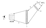
図1は、本発明の実施形態に係る像再生用ホログラムの記録の様子を示す図であり、図2は、本発明の実施形態に係るホログラム再生装置の構成を示す図である。この実施形態では、像再生用ホログラム1として透過型ホログラムを使用したものであり、また、再生する像が観察者に対して像再生用ホログラム1よりも手前に観察される実施形態となっている。
[Example 1]
FIG. 1 is a diagram illustrating a recording state of an image reproducing hologram according to an embodiment of the present invention, and FIG. 2 is a diagram illustrating a configuration of a hologram reproducing apparatus according to an embodiment of the present invention. In this embodiment, a transmission hologram is used as the
図2に示されるように、本実施形態に係るホログラム再生装置は、像再生用ホログラム1、光拡散素子としての拡散板2、コヒーレント光を走査する光源部4を備えて構成される。
As shown in FIG. 2, the hologram reproducing apparatus according to this embodiment includes an
図1には、像再生用ホログラム1の記録(作成)方法が示されている。像再生用記録材料11には、その同じ面に対して拡散板像再生ホログラム3a(記録用拡散素子)からの記録拡散光Rと、記録する像となる立体模型からの物体光Obが同時に照射される。本実施形態では、記録拡散光Rを形成する拡散板像再生ホログラム3aとして反射型ホログラムを用いることとしている。この、拡散板像再生ホログラム3aの作成方法については後述する。
FIG. 1 shows a method for recording (creating) an
物体光Obは、物体照明光(図示せず)を立体模型に対して照射することで形成される
。本実施形態では、記録拡散光Rを形成するための光源、並びに、物体光Obを形成するための光源として、同じレーザー光を2本に分岐して用いている。
The object light Ob is formed by irradiating the solid model with object illumination light (not shown). In the present embodiment, the same laser beam is branched into two as a light source for forming the recording diffused light R and a light source for forming the object light Ob.
像再生用記録材料11では、同時に照射された記録拡散光R(参照光)と物体光Obにより生じた干渉縞が記録される。干渉縞が記録された像再生用記録材料11は、現像もしくは加熱、紫外線照射等の適切な後処理を加えた後、像再生用ホログラム1となる。なお、像再生用ホログラム1としては体積型ホログラムを用いることが好ましい。体積型ホログラムは、内部に形成された干渉縞で回折光を生じさせるため、表面に凹凸を設ける必要が無く、ホログラムにて二次的に発生するスペックルノイズを抑えることができる。さらに、体積型ホログラムは、回折効率を高く設定することができ、0次透過光を効果的に抑制することができるため、設計者が意図する像を的確に再生することも可能となる。
In the
図2には、図1にて作成された像再生用ホログラム1の再生構成が示されている。本実施形態では、像再生用ホログラム1を再生する再生拡散光L(再生照明光)を形成するため、拡散板2が使用される。この拡散板2は、記録時において拡散板像3iが形成される位置、すなわち、拡散板像2と像再生用ホログラム1との位置関係が、図1における拡散板像3iと像再生用記録材料11の位置関係となるように配置される。本実施形態では、この拡散板2が、本発明における光拡散素子に相当している。
FIG. 2 shows a reproduction configuration of the
また、本実施形態では、光拡散素子として拡散板2を用いているが、本発明における光拡散素子は、拡散板2と同様の特性、すなわち、光拡散素子から発せられる再生拡散光Lが、像再生用ホログラム1を再生可能な程度に照明する特性(好ましくは、像再生用ホログラム1の全域を照明する)を有する光学素子であれば、微細なレンズがアレイ状に配列されて構成されたレンズアレイ、もしくは、通常の拡散板などを用いることとしてもよい。
In this embodiment, the
この拡散板2に対しては、光源部4にて形成されたコヒーレントな走査光Sが照射される。図3には、光源部4の構成例が示されている。この例では、光源部4は、コヒーレント光源としてのレーザー光源41と、走査型ミラーデバイス42にて構成されている。走査型ミラーデバイス42は、MEMS(Micro Electro Mechanical Systems)技術を用いて製造された2次元スキャナであって、本発明における走査型デバイスに相当している。この走査型ミラーデバイス42は、X軸廻り、Y軸廻りに共振振動することで、照射対象面を2次元的に走査する走査光Sを形成する。
The diffusing
時間的に照射位置を変化させて走査光Sを形成する光源部4としては、このような形態に限らず、2つの走査型ミラーデバイスで構成することや、面状に広がりを有するコヒーレント光を1次元走査するなど適宜形態を採用することが可能である。さらに、走査光Sを形成する走査型デバイスには、このような反射型のもの以外に、プリズム、回折格子などを用いた屈折型のものを採用することもできる。 The light source unit 4 that forms the scanning light S by changing the irradiation position with time is not limited to such a form, and may be composed of two scanning mirror devices, or may have coherent light having a planar shape. Appropriate forms such as one-dimensional scanning can be employed. Further, as the scanning device for forming the scanning light S, in addition to the reflection type device, a refraction type device using a prism, a diffraction grating, or the like may be employed.
本実施形態では、光拡散素子として拡散板2を2次元的に走査することしているが、光拡散素子としてホログラムを使用した場合には、例えば、ホログラムの各点からの再生照明光Lが、像再生用ホログラム1の全域を照射するようにすることが可能となり、走査光Sの走査範囲を1次元走査にするなど走査範囲を自由に選択したり、走査光Sの断面についても自由な形状を採用することが可能となる。
In this embodiment, the diffusing
再生時には、まず、光源部4から拡散板2に対して走査光Sが照射される。拡散板2は、各点において走査光Sを少なくとも像再生用ホログラム1の全域をカバーするように拡散させて再生拡散光Lを形成する。拡散板2で生じた再生拡散光Lは、像再生用ホログラム1に対する再生照明光として機能する。図2に示すように再生拡散光Lは、ちょうど像
再生用ホログラム1の記録時において、拡散板像3iを形成した記録拡散光Rと共役(方向が同じで向きが反対)となっている。本実施形態では、像再生用ホログラム1に透過型ホログラムを用いているため、像再生用ホログラム1では、再生拡散光Lを受けた面とは反対の面に再生光Iを回折し、像再生用ホログラム1の手前に再生像を結像する。
At the time of reproduction, first, the scanning light S is irradiated from the light source unit 4 to the
本発明では、特に、走査光Sを用いたことで、結果として光拡散素子(本実施形態では拡散板2)からの再生拡散光Lが像再生用ホログラム1に入射する角度が時間的に変化される。よって、光拡散素子で発生する固定された波面情報は像再生用ホログラム1で時間的に変化し平均化されることとなり、非コヒーレント光源を用いた場合と同等の画質を得ることができる。
In the present invention, in particular, by using the scanning light S, as a result, the angle at which the reproduction diffused light L from the light diffusing element (the
図4は、再生拡散光Lの時間的変化の様子を示した図である。図に示されるように像再生用ホログラム1の一点に着目すると、像再生用ホログラム1に入射する再生拡散光Lは、t1、t2、t3、t2、t1・・・という具合に入射角度が時間的に変化する。異なる角度からの入射角に対して散乱される波面が時間的に変化するため、複数の点から散乱された光同士の空間的な干渉パターンも時間的に変動することとなる。したがって、像再生用ホログラム1を観察した際には、再生像とともに観察されるスペックルパターンも時間的に変動し、平均化され不可視化されることになる。その結果、コヒーレント光で再生しながらも、スペックルノイズの低減した像を明瞭に観察することが可能となる。
FIG. 4 is a diagram showing the temporal change of the reproduction diffused light L. FIG. Focusing on one point of the
図5は、図1において像再生用ホログラム1の記録時に使用した、記録用拡散素子としての拡散板像再生ホログラム3aの記録方法を示した図である。記録時には、レーザー光を2本に分岐したうちの一方を拡散板22の背面より照射し、拡散板22の正面に拡散した光を物体光Bとして記録材料21の一方の面より入射させ、もう一方を記録材料21の他の面から参照光Cとして同時に入射させる。なお、参照光Cは、再生時に参照光Cと共役な再生照明光を生成可能であれば特に発散角度等は制限されない。また、拡散板22と再生時に使用する拡散板2とは同じ、あるいは、同等の特性を有するものが用いることが好ましい。
FIG. 5 is a diagram showing a recording method of the diffusion plate
物体光Bとしての拡散板22からの拡散光と、参照光Cは、記録材料21中で干渉縞を形成して記録する。記録材料21は、現像もしくは加熱、紫外線照射等の適切な後処理を加えた後、拡散板像再生ホログラム3aとなる。拡散板像再生ホログラム3aは、記録時に用いたレーザー光と同じ波長であって、記録時の参照光Cと逆向きに進行する(共役な)光を再生照明光として入射させることで、拡散板22を配置していた位置に拡散板像3iを再生する。
Diffused light from the
[実施例2]
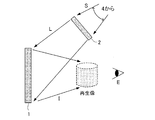
図6、図7は、他の実施形態に係るホログラム再生装置について説明する図であって、図6は、像再生用ホログラムの記録の様子を、また、図7は、ホログラム再生装置の構成を示す図である。実施例2では、像再生用ホログラム1として反射型ホログラムを使用したものであり、また、再生する像が観察者に対して像再生用ホログラム1よりも手前で観察される実施形態となっている。
[Example 2]
6 and 7 are diagrams for explaining a hologram reproducing apparatus according to another embodiment. FIG. 6 shows a state of recording an image reproducing hologram, and FIG. 7 shows a structure of the hologram reproducing apparatus. FIG. In the second embodiment, a reflection hologram is used as the
図6に示されているように、本実施形態では、記録用拡散光Rを形成する拡散板像再生ホログラム3a(記録用拡散素子)として透過型ホログラムを使用している。この拡散板像再生ホログラム3aは、拡散板像3iを再生するように記録拡散光Rを射出する。この記録拡散光Rが像再生用記録材料11に像を記録させる際の参照光となるようにする。なお、この拡散板像再生ホログラム3aの記録方法は後述する。拡散板像再生ホログラム3aから発生した記録拡散光R(参照光)と、立体模型からの物体光Obが、それぞれ像再生用記録材料11に対して相互に反対側の面から同時に照射されることで両者の干渉縞が
像再生用記録材料11に記録される。干渉縞が記録された像再生用記録材料11は、現像もしくは加熱、紫外線照射等の適切な後処理を加えた後、像再生用ホログラム1となる。
As shown in FIG. 6, in this embodiment, a transmission hologram is used as the diffusion plate
このようにして作成された像再生用ホログラム1は、図7に示された構成にて再生される。すなわち、像再生用ホログラム1に対し、記録時において拡散板像3iが再生された位置に拡散板2が配置される。拡散板2には、記録時と同じ波長を有する走査光Sが光源部4から照射される。光源部4の構成は実施例1と同様である。拡散板2は、その各点から発生する再生拡散光Lが、それぞれ像再生用ホログラム1の少なくとも全域を照明する拡散特性を有するものを使用することで、光源部4が拡散板2のいずれの点を走査している場合でも、像再生用ホログラム1からは同じ位置に再生像が形成されることとなる。
The
拡散板2の背面から光源部4にて発生させた走査光Sを入射させ、拡散板2の正面から再生拡散光Lを出射させる。このように本実施形態では、この拡散板2が光拡散素子として機能し、拡散板2による再生拡散光Lが像再生用ホログラム1の再生照明光となる。実施例1と同様、本実施形態においても光源部4からの走査光Sが拡散板2に入射する。そのため、像再生用ホログラム1に入射する再生拡散光Lは、実施例1と同様、時間的に入射角度が変化することとなり、その結果、観察者Eに対してスペックルノイズの低減した像を観察させることとなる。
The scanning light S generated by the light source unit 4 is incident from the back surface of the
図8は、図6において像再生用ホログラム1の記録時に使用した、記録用拡散素子としての拡散板像再生ホログラム3aの記録方法を示した図である。記録時には、レーザー光を2本に分岐したうちの一方を拡散板22の背面より照射し、拡散板22の正面に拡散した光を物体光Bとして、もう一方を参照光Cとして記録材料21の同じ面から同時に入射させる。この実施形態においても、参照光Cは、再生時に参照光Cと共役な再生照明光を生成可能であれば特に発散角度等を制限する必要はない。
FIG. 8 is a diagram showing a recording method of the diffusion plate
物体光Bとしての拡散板22からの拡散光と、参照光Cは、記録材料21中で干渉縞を形成して記録する。記録材料21は、現像もしくは加熱、紫外線照射等の適切な後処理を加えた後、拡散板像再生ホログラム3aとなる。拡散板像再生ホログラム3aは、記録時に用いたレーザー光と同じ波長であって、記録時の参照光Cと逆向きに進行する(共役な)光を再生照明光として入射させることで、拡散板22を配置していた位置に拡散板像3iを再生する。
Diffused light from the
[実施例3]
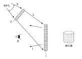
図9、図10は、他の実施形態に係るホログラム再生装置について説明する図であって、図9は、像再生用ホログラムの記録の様子を、また、図10は、ホログラム再生装置の構成を示す図である。実施例3では、像再生用ホログラム1として透過型ホログラムを使用したものであり、また、再生する像が観察者に対して像再生用ホログラム1よりも奥に観察される実施形態となっている。
[Example 3]
9 and 10 are diagrams for explaining a hologram reproducing apparatus according to another embodiment. FIG. 9 shows a state of recording an image reproducing hologram, and FIG. 10 shows a structure of the hologram reproducing apparatus. FIG. In the third embodiment, a transmission hologram is used as the
図9に示されているように、像再生用記録材料11の同じ面に対して、拡散板3b(記録用拡散素子)からの記録拡散光R(参照光)と立体模型からの物体光Obがそれぞれ入射される。像再生用記録材料11中で生じた記録拡散光Rと物体光Obの干渉縞が記録される。像再生用記録材料11は現像もしくは加熱、紫外線照射等の適切な後処理を加えた後、像再生用ホログラム1となる。
As shown in FIG. 9, the recording diffused light R (reference light) from the
再生時には、図10に示されているように、像再生用ホログラム1に対して、記録時に使用した拡散板3bと同じ位置関係となるよう拡散板2が配置される。拡散板2は、像再生用ホログラム1による再生像と重なって観察されないように配置される。具体的には、図に示すように像再生ホログラム1の光軸と拡散板2の光軸をずらしておくことで実現さ
れる。拡散板2が再生像と重なる位置に配置されると、再生像に拡散板2にて発生するスペックルノイズが同時に観察され再生像を見づらくしてしまう。
At the time of reproduction, as shown in FIG. 10, the
拡散板2に対しては、光源部4からの走査光Sが入射され、拡散板2の前面からは再生拡散光Lが出射される。この実施形態における光源部4は、前述したものと同様であって、コヒーレント光の照射位置を時間的に変化させて走査光を形成する。また、拡散板2は、前述の実施例と同様、各点から発生する再生拡散光Lが、それぞれ像再生用ホログラム1の少なくとも全域を照明する拡散特性を有するものが使用される。
Scanning light S from the light source unit 4 is incident on the
観察者Eは、像再生用ホログラム1に対し、再生拡散光Lが照射される側とは反対側に視点を置くことで、像再生用ホログラム1よりも奥側に再生像(虚像)を観察することが可能となる。この実施例3においても、像再生用ホログラム1に対して照射される再生拡散光Lは、時間的に入射角度が変化することとなるため、結果としてスペックルノイズを低減した像が提供される。
The observer E observes the reproduction image (virtual image) on the back side of the
本実施形態においても前述の実施形態と同様、光拡散素子としての拡散板2に対しては、その向きを時間的に変化させる走査光Sが照射される。また、拡散板2は、実施例2で説明したように、各点から発生する再生拡散光Lが、それぞれ像再生用ホログラム1の少なくとも全域を照明する拡散特性を有するものが使用される。この実施例3においても、像再生用ホログラム1に対して照射される再生拡散光Lは、時間的に入射角度が変化することとなるため、結果としてスペックルノイズを低減した像が提供される。
Also in this embodiment, similarly to the above-described embodiment, the diffusing
[実施例4]
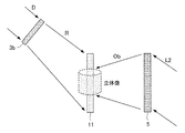
図11、図12は、他の実施形態に係るホログラム再生装置について説明する図であって、図11は、像再生用ホログラムの記録の様子を、また、図12は、ホログラム再生装置の構成を示す図である。実施例4では、像再生用ホログラム1として反射型ホログラムを使用したものであり、また、再生する像が観察者に対して像再生用ホログラム1よりも奥に観察される実施形態となっている。
[Example 4]
FIGS. 11 and 12 are diagrams for explaining a hologram reproducing apparatus according to another embodiment. FIG. 11 shows a state of recording an image reproducing hologram, and FIG. 12 shows a structure of the hologram reproducing apparatus. FIG. In the fourth embodiment, a reflection hologram is used as the
図11に示されているように、像再生用記録材料11の異なる面に対して、拡散板3bからの記録拡散光R(参照光)と立体模型からの物体光Obがそれぞれ入射される。像再生用記録材料11中で生じた記録拡散光Rと物体光Obの干渉縞が記録される。像再生用記録材料11は現像もしくは加熱、紫外線照射等の適切な後処理を加えた後、像再生用ホログラム1となる。
As shown in FIG. 11, recording diffused light R (reference light) from the
再生時には、図12に示されているように、像再生用ホログラム1に対して、記録時に使用した拡散板3bと同じ位置関係となるよう拡散板2が配置される。拡散板2に対しては、光源部4からの走査光Sが入射され、拡散板2の前面からは再生拡散光Lが出射される。この実施形態における光源部4は、前述したものと同様であって、コヒーレント光の照射位置を時間的に変化させて走査光を形成する。また、拡散板2は、前述の実施例と同様、各点から発生する再生拡散光Lが、それぞれ像再生用ホログラム1の少なくとも全域を照明する拡散特性を有するものが使用される。この実施例4においても、像再生用ホログラム1に対して照射される再生拡散光Lは、時間的に入射角度が変化することとなるため、結果としてスペックルノイズを低減した像が提供される。
At the time of reproduction, as shown in FIG. 12, the
[実施例5]
図13、図14は、他の実施形態に係るホログラム再生装置について説明する図であって、図13は、像再生用ホログラムの記録の様子を、また、図14は、ホログラム再生装置の構成を示す図である。この実施例5では、像再生用ホログラム1としてイメージ型ホログラムを使用したものであって、再生像は、その一部を像再生用ホログラム1に重ねて
、あるいは、像再生用ホログラム1の近傍にて観察される実施形態となっている。
[Example 5]
FIGS. 13 and 14 are diagrams for explaining a hologram reproducing apparatus according to another embodiment. FIG. 13 shows a state of recording an image reproducing hologram, and FIG. 14 shows a structure of the hologram reproducing apparatus. FIG. In the fifth embodiment, an image hologram is used as the
図13に示されるように記録時には、拡散板3bからの記録拡散光Rを参照光として使用する。一方、記録させる立体像は、像再生用記録材料11の内部、もしくは、近傍に位置するため、立体模型による記録は困難となる。そのため、記録像再生用ホログラム5による物体光Obを使用することで像再生用記録材料11の内部、もしくは、近傍に立体像を結像させることとしている。記録像再生用ホログラム5は、通常の記録方法にて立体像を記録させた透過型ホログラムであって、再生照明光L2と共役な参照光と、立体像の物体光とを干渉させて記録されたものである。このように像再生用記録材料11の一面に記録拡散光Rを、他面に物体光Obを同時に照射することで、像再生用記録材料11中に干渉縞を形成し、干渉縞の情報が記録される。像再生用記録材料11は現像もしくは加熱、紫外線照射等の適切な後処理を加えた後、像再生用ホログラム1となる。
As shown in FIG. 13, during recording, the recording diffused light R from the
図14に示されるように、像再生用ホログラム1に対して、記録時に使用した拡散板3bと同じ位置関係となるように拡散板2が設置される。拡散板2に対しては、光源部4からの走査光Sが入射され、拡散板2の前面からは再生拡散光L(再生照明光)が照射される。この実施形態における光源部4は、前述したものと同様、光拡散素子としての拡散板2に対して走査光を照射する。この実施例5においても、像再生用ホログラム1に対して照射される再生拡散光Lは、時間的に入射角度が変化することとなるため、結果としてスペックルノイズを低減した像が提供される。
As shown in FIG. 14, the
このようなイメージ型ホログラムでは、形成する再生像が像再生用ホログラム1に対して近く位置するため、再生拡散光Lの誤差に対する影響が少ないものとなる。したがって、再生時に使用する拡散板2の配置位置、配置角度、照射特性などを、記録時のものと厳密に一致させなくても、ボケの少ない再生像を提供することが可能となり、再生時の構成に自由度を持たせることが可能となる。
In such an image type hologram, the reproduced image to be formed is located close to the
以上、実施例1〜実施例5の記録では、物体光Obと記録拡散光Rとを干渉させることで干渉縞の記録(干渉露光)を行うこととしたが、計算機にて計算された干渉縞を直接、像再生用記録材料11に記録する、いわゆる計算機ホログラムを採用するものであってもよい。
As described above, in the recording of the first to fifth embodiments, the interference fringes are recorded (interference exposure) by causing the object light Ob and the recording diffused light R to interfere with each other. However, the interference fringes calculated by the computer are used. A so-called computer generated hologram may be employed in which the image is directly recorded on the image reproducing
表1には、各種条件下におけるスペックルコントラストが示されている。(1)、(2)は、比較のためであって、それぞれ、レーザー平行光のみの場合、単色LEDを用いた場合の測定結果である。(3)、(4)は、本発明の実施形態に係る測定結果であって、それぞれ、光拡散素子として体積型ホログラム、計算機ホログラムを用いた場合の測定結果である。スペックルコントラストは、以下の数式(1)にて表される。なお、測定には、光源としてDPSSレーザー(532nm)を用いて像再生用ホログラムに投影した。この測定で使用した体積型ホログラムは、拡散角、すなわち、像再生用ホログラムの一点に入射する光線群が形成する円錐の頂角は20°となるように作成されたものである。そして、各ホログラムの記録材料には、532nmに感度を持つフォトポリマー材料(先行技術文献としてあげた特許文献3の実施例1に記載の材料)を使用している。
SC=σ/I×100
=1/(Modes)0.5×100 ・・・(1)
SC:スペックルコントラスト
σ :輝度の標準偏差
I :輝度平均値
Modes:パターンの数(統計的に独立しているスペックルの数)
Table 1 shows speckle contrast under various conditions. (1) and (2) are for comparison, and are measurement results in the case where only a laser parallel light is used and a monochromatic LED is used. (3) and (4) are measurement results according to the embodiment of the present invention, and are measurement results when a volume hologram and a computer generated hologram are used as the light diffusing element, respectively. The speckle contrast is expressed by the following formula (1). For the measurement, a DPSS laser (532 nm) was used as a light source and projected onto a hologram for image reproduction. The volume hologram used in this measurement was prepared so that the diffusion angle, that is, the apex angle of the cone formed by the light beam incident on one point of the image reproduction hologram was 20 °. As a recording material for each hologram, a photopolymer material having sensitivity at 532 nm (the material described in Example 1 of Patent Document 3 cited as the prior art document) is used.
SC = σ / I × 100
= 1 / (Modes) 0.5 x 100 (1)
SC: speckle contrast σ: standard deviation of luminance I: luminance average value Modes: number of patterns (number of statistically independent speckles)

なお、本発明はこれらの実施形態のみに限られるものではなく、それぞれの実施形態の構成を適宜組み合わせて構成した実施形態も本発明の範疇となるものである。 Note that the present invention is not limited to these embodiments, and embodiments configured by appropriately combining the configurations of the respective embodiments also fall within the scope of the present invention.
11…像再生用記録材料
1…像再生用ホログラム
2…拡散板(光拡散素子)
21…(拡散板像再生用)記録材料
22…拡散板
3a…拡散板像再生ホログラム(記録用拡散素子)
3b…拡散板(記録用拡散素子)
3i…拡散板像
4…光源部
41…レーザー光源(コヒーレント光源)
42…走査型ミラーデバイス(走査型デバイス)
5…記録像再生用ホログラム
DESCRIPTION OF
21 ... (for diffusion plate image reproduction)
3b ... Diffusion plate (diffusing element for recording)
3i ... Diffuser image 4 ...
42 ... Scanning mirror device (scanning device)
5 ... Hologram for reproducing recorded image
Claims (9)
前記光源部にて形成された走査光を拡散させて拡散光を形成する光拡散素子と、
拡散光を参照光として像を記録される像再生用ホログラムと、を備え、
前記光拡散素子にて形成された拡散光を再生照明光として、前記像再生用ホログラムに記録される像を再生することを特徴とする
ホログラム再生装置。 A light source unit that forms scanning light by temporally changing the irradiation position of the coherent light;
A light diffusing element for diffusing scanning light formed by the light source unit to form diffused light;
An image reproducing hologram for recording an image using diffused light as reference light, and
A hologram reproducing apparatus, which reproduces an image recorded on the image reproducing hologram by using diffused light formed by the light diffusing element as reproduction illumination light.
請求項1に記載のホログラム再生装置。 The hologram reproducing apparatus according to claim 1, wherein the light source unit includes a scanning device that forms scanning light by temporally deflecting a beam emitted from a coherent light source.
請求項1または請求項2に記載のホログラム再生装置。 The hologram reproducing apparatus according to claim 1, wherein the image reproducing hologram is any one of a transmission hologram and a reflection hologram.
前記光拡散素子は、前記像再生用ホログラムにて再生する像と重なって観察されないように配置されることを特徴とする
請求項3に記載のホログラム再生装置。 The image reproducing hologram is a transmission hologram,
The hologram reproducing apparatus according to claim 3, wherein the light diffusing element is disposed so as not to be overlapped with an image reproduced by the image reproducing hologram.
請求項4または請求項5に記載のホログラム再生装置。 The hologram reproducing apparatus according to claim 4, wherein the image reproducing hologram is an image hologram.
請求項1から請求項5の何れかに記載のホログラム再生装置。 The hologram reproducing apparatus according to claim 1, wherein the light diffusing element is a diffusing plate.
請求項1から請求項5の何れかに記載のホログラム再生装置。 The hologram reproducing apparatus according to claim 1, wherein the light diffusing element is a hologram.
請求項1から請求項5の何れかに記載のホログラム再生装置。 The hologram reproducing apparatus according to claim 1, wherein the light diffusing element is a lens array.
請求項1から請求項8の何れか1項に記載のホログラム再生装置。 The hologram according to any one of claims 1 to 8, wherein the diffused light formed by the light diffusing element is conjugate with reference light used when recording the image reproducing hologram. Playback device.
Priority Applications (1)
| Application Number | Priority Date | Filing Date | Title |
|---|---|---|---|
| JP2010263100A JP2012113183A (en) | 2010-11-26 | 2010-11-26 | Hologram reproduction device |
Applications Claiming Priority (1)
| Application Number | Priority Date | Filing Date | Title |
|---|---|---|---|
| JP2010263100A JP2012113183A (en) | 2010-11-26 | 2010-11-26 | Hologram reproduction device |
Publications (1)
| Publication Number | Publication Date |
|---|---|
| JP2012113183A true JP2012113183A (en) | 2012-06-14 |
Family
ID=46497439
Family Applications (1)
| Application Number | Title | Priority Date | Filing Date |
|---|---|---|---|
| JP2010263100A Pending JP2012113183A (en) | 2010-11-26 | 2010-11-26 | Hologram reproduction device |
Country Status (1)
| Country | Link |
|---|---|
| JP (1) | JP2012113183A (en) |
Cited By (3)
| Publication number | Priority date | Publication date | Assignee | Title |
|---|---|---|---|---|
| CN107121917A (en) * | 2017-05-09 | 2017-09-01 | 四川大学 | A kind of method for suppressing to calculate holographic speckle noise |
| CN108398804A (en) * | 2018-03-28 | 2018-08-14 | 四川长虹电器股份有限公司 | A kind of laser dissipation spot light path and laser projection light-source system |
| CN113917818A (en) * | 2021-09-01 | 2022-01-11 | 华南师范大学 | Light beam coding system and method based on spatial light modulator |
Citations (5)
| Publication number | Priority date | Publication date | Assignee | Title |
|---|---|---|---|---|
| JPH0777924A (en) * | 1993-09-10 | 1995-03-20 | Nikon Corp | Holography reconstructing method and device |
| JPH07104647A (en) * | 1993-10-05 | 1995-04-21 | Nikon Corp | Hologram forming method and device therefor |
| JP2008191279A (en) * | 2007-02-02 | 2008-08-21 | Seiko Epson Corp | Image display apparatus |
| JP2008197335A (en) * | 2007-02-13 | 2008-08-28 | Dainippon Printing Co Ltd | Method for producing hologram for security |
| JP2009042372A (en) * | 2007-08-07 | 2009-02-26 | Seiko Epson Corp | Projector and projection device |
-
2010
- 2010-11-26 JP JP2010263100A patent/JP2012113183A/en active Pending
Patent Citations (5)
| Publication number | Priority date | Publication date | Assignee | Title |
|---|---|---|---|---|
| JPH0777924A (en) * | 1993-09-10 | 1995-03-20 | Nikon Corp | Holography reconstructing method and device |
| JPH07104647A (en) * | 1993-10-05 | 1995-04-21 | Nikon Corp | Hologram forming method and device therefor |
| JP2008191279A (en) * | 2007-02-02 | 2008-08-21 | Seiko Epson Corp | Image display apparatus |
| JP2008197335A (en) * | 2007-02-13 | 2008-08-28 | Dainippon Printing Co Ltd | Method for producing hologram for security |
| JP2009042372A (en) * | 2007-08-07 | 2009-02-26 | Seiko Epson Corp | Projector and projection device |
Cited By (4)
| Publication number | Priority date | Publication date | Assignee | Title |
|---|---|---|---|---|
| CN107121917A (en) * | 2017-05-09 | 2017-09-01 | 四川大学 | A kind of method for suppressing to calculate holographic speckle noise |
| CN107121917B (en) * | 2017-05-09 | 2019-05-31 | 四川大学 | A method of inhibit to calculate holographic speckle noise |
| CN108398804A (en) * | 2018-03-28 | 2018-08-14 | 四川长虹电器股份有限公司 | A kind of laser dissipation spot light path and laser projection light-source system |
| CN113917818A (en) * | 2021-09-01 | 2022-01-11 | 华南师范大学 | Light beam coding system and method based on spatial light modulator |
Similar Documents
| Publication | Publication Date | Title |
|---|---|---|
| JP6304337B2 (en) | Illumination device, projection device, and projection-type image display device | |
| JP5541462B2 (en) | Projection-type image display device | |
| TW200300525A (en) | Hologram production method | |
| US9154756B2 (en) | Projection apparatus and hologram recording medium | |
| TWI518371B (en) | Surface lighting device and backlight device | |
| JP6041093B2 (en) | Hologram reproduction device, hologram reproduction method, and projection-type image display device | |
| WO2012141254A1 (en) | Illumination device, projection device, and projection-type image display device | |
| JP5736746B2 (en) | Exposure equipment | |
| JP2012113183A (en) | Hologram reproduction device | |
| JP5804245B2 (en) | Scanning display device | |
| TWI640721B (en) | Surface lighting device and backlight device | |
| JP5765032B2 (en) | Illumination device, projection device, and projection-type image display device | |
| JP2015114562A (en) | Lighting unit, projection type video display device, optical device, and optical element | |
| JP6598100B2 (en) | Illumination device, projection device, and projection-type image display device | |
| JPH0812283B2 (en) | Diffraction grating exposure device | |
| JP6460182B2 (en) | Illumination device and light deflection device | |
| JP5812390B2 (en) | Illumination device, projection device, and projection-type image display device | |
| KR20030025279A (en) | Hologram producing method | |
| JP5510826B2 (en) | Illumination device, projection device, and projection-type image display device | |
| JP6198151B2 (en) | Illumination device and light deflection device | |
| JP5549816B2 (en) | Backlight device | |
| JP6186843B2 (en) | Illumination device, projection device, and projection-type image display device |
Legal Events
| Date | Code | Title | Description |
|---|---|---|---|
| A621 | Written request for application examination |
Free format text: JAPANESE INTERMEDIATE CODE: A621 Effective date: 20130926 |
|
| RD04 | Notification of resignation of power of attorney |
Free format text: JAPANESE INTERMEDIATE CODE: A7424 Effective date: 20131108 |
|
| A977 | Report on retrieval |
Free format text: JAPANESE INTERMEDIATE CODE: A971007 Effective date: 20140326 |
|
| A131 | Notification of reasons for refusal |
Free format text: JAPANESE INTERMEDIATE CODE: A131 Effective date: 20140409 |
|
| A521 | Written amendment |
Free format text: JAPANESE INTERMEDIATE CODE: A523 Effective date: 20140529 |
|
| A02 | Decision of refusal |
Free format text: JAPANESE INTERMEDIATE CODE: A02 Effective date: 20141119 |