JP2012110676A - Access apparatus including desufflation control mechanism - Google Patents
Access apparatus including desufflation control mechanism Download PDFInfo
- Publication number
- JP2012110676A JP2012110676A JP2011196355A JP2011196355A JP2012110676A JP 2012110676 A JP2012110676 A JP 2012110676A JP 2011196355 A JP2011196355 A JP 2011196355A JP 2011196355 A JP2011196355 A JP 2011196355A JP 2012110676 A JP2012110676 A JP 2012110676A
- Authority
- JP
- Japan
- Prior art keywords
- valve
- access device
- control mechanism
- opening
- longitudinal passage
- Prior art date
- Legal status (The legal status is an assumption and is not a legal conclusion. Google has not performed a legal analysis and makes no representation as to the accuracy of the status listed.)
- Withdrawn
Links
Images


Classifications
-
- A—HUMAN NECESSITIES
- A61—MEDICAL OR VETERINARY SCIENCE; HYGIENE
- A61B—DIAGNOSIS; SURGERY; IDENTIFICATION
- A61B17/00—Surgical instruments, devices or methods, e.g. tourniquets
- A61B17/34—Trocars; Puncturing needles
- A61B17/3498—Valves therefor, e.g. flapper valves, slide valves
-
- A—HUMAN NECESSITIES
- A61—MEDICAL OR VETERINARY SCIENCE; HYGIENE
- A61M—DEVICES FOR INTRODUCING MEDIA INTO, OR ONTO, THE BODY; DEVICES FOR TRANSDUCING BODY MEDIA OR FOR TAKING MEDIA FROM THE BODY; DEVICES FOR PRODUCING OR ENDING SLEEP OR STUPOR
- A61M13/00—Insufflators for therapeutic or disinfectant purposes, i.e. devices for blowing a gas, powder or vapour into the body
- A61M13/003—Blowing gases other than for carrying powders, e.g. for inflating, dilating or rinsing
-
- A—HUMAN NECESSITIES
- A61—MEDICAL OR VETERINARY SCIENCE; HYGIENE
- A61B—DIAGNOSIS; SURGERY; IDENTIFICATION
- A61B17/00—Surgical instruments, devices or methods, e.g. tourniquets
- A61B17/34—Trocars; Puncturing needles
- A61B17/3474—Insufflating needles, e.g. Veress needles
-
- A—HUMAN NECESSITIES
- A61—MEDICAL OR VETERINARY SCIENCE; HYGIENE
- A61B—DIAGNOSIS; SURGERY; IDENTIFICATION
- A61B2218/00—Details of surgical instruments, devices or methods for transferring non-mechanical forms of energy to or from the body
- A61B2218/001—Details of surgical instruments, devices or methods for transferring non-mechanical forms of energy to or from the body having means for irrigation and/or aspiration of substances to and/or from the surgical site
- A61B2218/007—Aspiration
- A61B2218/008—Aspiration for smoke evacuation
Landscapes
- Health & Medical Sciences (AREA)
- Life Sciences & Earth Sciences (AREA)
- General Health & Medical Sciences (AREA)
- Veterinary Medicine (AREA)
- Heart & Thoracic Surgery (AREA)
- Surgery (AREA)
- Biomedical Technology (AREA)
- Animal Behavior & Ethology (AREA)
- Engineering & Computer Science (AREA)
- Public Health (AREA)
- Anesthesiology (AREA)
- Pathology (AREA)
- Nuclear Medicine, Radiotherapy & Molecular Imaging (AREA)
- Hematology (AREA)
- Medical Informatics (AREA)
- Molecular Biology (AREA)
- Surgical Instruments (AREA)
Abstract
Description
(関連出願の相互参照)
本出願は、2010年11月23日に出願された米国仮出願番号61/416,559の利益を主張し、この出願に対し優先権を主張し、この全内容は本明細書に参照により援用される。
(Cross-reference of related applications)
This application claims the benefit of, and claims priority to, US Provisional Application No. 61 / 416,559, filed on November 23, 2010, the entire contents of which are incorporated herein by reference. Is done.
(技術分野)
本開示は、アクセス装置に関し、さらに詳細には、脱気制御メカニズムを含むアクセス装置に関する。
(Technical field)
The present disclosure relates to access devices, and more particularly to access devices that include a degassing control mechanism.
(関連技術分野の説明)
腹腔鏡処置では、医師は、小さい切開口を通して腹部の内部で外科手術を実行し、内視鏡処置では、医師は、皮膚の小さな入口となる切開口を通して挿入される細いチューブまたはカニューレを通して体の任意の中空内臓で外科手術を執り行う。特定の場面では、1つ以上の吹送ポートは、細いチューブまたはカニューレに操作可能に関連付けられ、細いチューブまたはカニューレが切開口に挿入され、患者に固定された後に、腹腔に加圧ガス(例えば、CO2)を提供するように構成され、その結果として気腹をもたらす。加圧ガスは、内部臓器から離れるように内部体壁を引き上げる陽圧を提供し、それにより外科医に手術する空間を提供する。手術する空間をつくることにより、医師はカニューレアセンブリを通して挿入される器具で臓器に必要なく接触することを回避する。
(Description of related technical fields)
In a laparoscopic procedure, a doctor performs a surgical operation inside the abdomen through a small incision, and in an endoscopic procedure, the doctor passes through a thin tube or cannula inserted through the incision that becomes a small entrance to the skin Perform surgery on any hollow internal organ. In certain situations, one or more insufflation ports are operably associated with a thin tube or cannula, and after the thin tube or cannula is inserted into the incision and secured to the patient, a pressurized gas (eg, Configured to provide (CO 2 ), resulting in pneumonia. The pressurized gas provides a positive pressure that pulls up the internal body wall away from the internal organs, thereby providing a space for surgery to the surgeon. By creating a space for surgery, the physician avoids unnecessary contact with the organ with instruments inserted through the cannula assembly.
外科手術処置中に、医師が腹腔内の加圧ガスの量を変更することが必要とされ得る。すなわち、特定の外科手術環境において、外科手術処置中に、腹腔でさらに吹送および/または脱気することが必要とされ得る。例えば、組織が結紮および/または焼灼され得る以前に記述された外科手術処置の1つ(例えば、腹腔鏡処置)の間に、煙が腹腔を満たし得る。煙に満たされた腹腔は、一般的に医師に所望されないことが認識される。さらに詳細には、腹腔内に含まれている煙は、とりわけ治療されている組織を医師が鮮明に見ることを妨げ得る。一般的には、腹腔に含まれる煙を排除および/または排出することは、腹腔を脱気することにより達成される。特定の外科手術環境において、腹腔からの煙の排除および/または排出を加速するために、脱気流を増加することが必要とされ得る。 During the surgical procedure, it may be necessary for the physician to change the amount of pressurized gas in the abdominal cavity. That is, in certain surgical environments, further insufflation and / or degassing may be required in the abdominal cavity during a surgical procedure. For example, smoke can fill the abdominal cavity during one of the previously described surgical procedures (eg, laparoscopic procedures) where tissue can be ligated and / or cauterized. It is recognized that abdominal cavity filled with smoke is generally not desired by a physician. More particularly, smoke contained within the abdominal cavity can prevent the physician from seeing clearly the tissue being treated, among other things. Generally, eliminating and / or expelling smoke contained in the abdominal cavity is accomplished by degassing the abdominal cavity. In certain surgical environments, it may be necessary to increase the airflow to accelerate the removal and / or elimination of smoke from the abdominal cavity.
従って、医師が腹腔内の組織を効果的に治療し得るように、医師が、腹腔内の加圧ガスの脱気流をより効果的に制御する能力を有することが有益であり得る。 Thus, it may be beneficial for a physician to have the ability to more effectively control the degassing of pressurized gas within the abdominal cavity so that the physician can effectively treat tissue within the abdominal cavity.
本開示は、外科手術処置での使用のためのアクセス装置を提供する。アクセス装置は、
長手方向の軸を規定し、長手方向の通路を有するアクセス部材を含む。長手方向の通路は、外科手術処置を実行することに使用される外科手術用器具の通過を可能にするように適合される。ハウジングは、外科手術用器具の通過を可能にするために、アクセス部材の長手方向の通路と連絡関係にある開口を規定する近位端を含む。ゼロ閉鎖弁は、長手方向の通路内に配置され、ゼロ閉鎖弁から挿入される外科手術用器具がない場合に実質的に流体密のシールを提供するように構成される。制御メカニズムは、アクセス装置に操作可能に結合され、アクセス装置の脱気流を制御するように構成される。制御メカニズムは、長手方向の通路と流体連絡関係にある細長い弁を含む。弁は、その弁の長さに沿って操作可能に配置された少なくとも1つの開口を含む。制御メカニズムは、弁に操作可能に結合され、開口と操作的連絡関係にある選択的に移動可能な機械インターフェイスを含む。選択的に移動可能な機械インターフェイスは、弁の長さに沿って動かされるときに脱気流を変更するように構成される。
The present disclosure provides an access device for use in a surgical procedure. Access device
An access member is defined that defines a longitudinal axis and has a longitudinal passage. The longitudinal passage is adapted to allow passage of a surgical instrument used to perform a surgical procedure. The housing includes a proximal end that defines an opening in communication with the longitudinal passage of the access member to allow passage of a surgical instrument. The zero closure valve is disposed within the longitudinal passage and is configured to provide a substantially fluid tight seal when no surgical instrument is inserted through the zero closure valve. The control mechanism is operably coupled to the access device and is configured to control degassing of the access device. The control mechanism includes an elongate valve in fluid communication with the longitudinal passage. The valve includes at least one opening operably disposed along the length of the valve. The control mechanism includes a selectively movable mechanical interface operably coupled to the valve and in operative communication with the opening. The selectively movable mechanical interface is configured to change the deaeration when moved along the length of the valve.
本開示は、アクセス装置の脱気流を制御するように構成される制御メカニズムを提供する。制御メカニズムは、長手方向の通路と流体連絡関係にある細長い弁を含む。弁は、弁の長さに沿って操作可能に配置された少なくとも1つの開口を含む。制御メカニズムは、弁に操作可能に結合され、開口と操作的連絡関係にある選択的に移動可能な機械インターフェイスを含む。選択的に移動可能な機械インターフェイスは、弁の長さに沿って動かされるとき、脱気流を変更するように構成される。 The present disclosure provides a control mechanism configured to control degassing of an access device. The control mechanism includes an elongate valve in fluid communication with the longitudinal passage. The valve includes at least one opening operably disposed along the length of the valve. The control mechanism includes a selectively movable mechanical interface operably coupled to the valve and in operative communication with the opening. The selectively movable mechanical interface is configured to change the de-air flow when moved along the length of the valve.
本開示は、外科手術処置での使用のためのアクセス装置も提供する。アクセス装置は、長手方向の軸を規定し、長手方向の通路を有するアクセス部材を含む。長手方向の通路は外科手術処置を実行することに使用される外科手術用器具の通過を可能にするように適合される。ハウジングは、外科手術用器具の通過を可能にするために、アクセス部材の長手方向の通路と連絡関係にある開口を規定する近位端を含む。ゼロ閉鎖弁は、長手方向の通路内に配置され、ゼロ閉鎖弁から挿入される外科手術用器具がない場合に実質的に流体密のシールを提供するように構成される。制御メカニズムは、アクセス装置の脱気流を制御するように構成される。制御メカニズムは、長手方向の通路と流体連絡関係にある弁を含む。弁は、少なくとも1つの開口と、弁に操作可能に結合された選択的に移動可能な機械インターフェイスとを含む。選択的に移動可能な機械インターフェイスは、弁に対して1つ以上の開口にわたって動かされるときに脱気流を変更するように構成される。 The present disclosure also provides an access device for use in a surgical procedure. The access device includes an access member defining a longitudinal axis and having a longitudinal passage. The longitudinal passage is adapted to allow passage of a surgical instrument used to perform a surgical procedure. The housing includes a proximal end that defines an opening in communication with the longitudinal passage of the access member to allow passage of a surgical instrument. The zero closure valve is disposed within the longitudinal passage and is configured to provide a substantially fluid tight seal when no surgical instrument is inserted through the zero closure valve. The control mechanism is configured to control degassing of the access device. The control mechanism includes a valve in fluid communication with the longitudinal passage. The valve includes at least one opening and a selectively movable mechanical interface operably coupled to the valve. The selectively movable mechanical interface is configured to change the deaeration when moved over one or more openings relative to the valve.
本発明は例えば以下を提供する。
(項目1) 長手方向の軸を規定し、長手方向の通路を有するアクセス部材であって、上記長手方向の通路は、外科手術処置を実行することに使用される外科手術用器具の通過を可能にするように適合される、アクセス部材と、
上記外科手術用器具の通過を可能にするために、上記アクセス部材の長手方向の通路と連絡関係にある開口を規定する近位端を含むハウジングと、
上記長手方向の通路内に配置されたゼロ閉鎖弁であって、上記ゼロ閉鎖弁を通って挿入される上記外科手術用器具がない場合に実質的に流体密のシールを提供するように構成されたゼロ閉鎖弁と、
上記アクセス装置に操作可能に結合され、上記アクセス装置の脱気流を制御するように構成された制御メカニズムであって、上記制御メカニズムは、上記長手方向の通路と流体連絡関係にある細長い弁を含み、上記細長い弁は、上記弁の長さに沿って操作可能に配置された1つ以上の開口を含み、上記制御メカニズムは、上記弁に操作可能に結合され、上記少なくとも1つの開口と操作的連絡関係にある選択的に移動可能な機械インターフェイスを含み、上記選択的に移動可能な機械インターフェイスは、上記弁の長さに沿って動くときに脱気流を変更するように構成される、制御メカニズムと
を含む、外科手術処置での使用のためのアクセス装置。
(項目2) 上記弁がねじ山を付けられている、上記項目に記載のアクセス装置。
(項目3) 上記選択的に移動可能な機械インターフェイスは、上記アクセス装置に繋留される、上記項目のいずれかに記載のアクセス装置。
(項目4) 上記選択的に移動可能な機械インターフェイスはキャップである、上記項目のいずれかに記載のアクセス装置。
(項目5) 上記選択的に移動可能な機械インターフェイスは、上記弁に回転可能に結合される、上記項目のいずれかに記載のアクセス装置。
(項目6) 上記選択的に移動可能な機械インターフェイスは、プラグである、上記項目のいずれかに記載のアクセス装置。
(項目7) 上記選択的に移動可能な機械インターフェイスは、上記弁にスライド可能に結合され、上記弁内で可動的である、上記項目のいずれかに記載のアクセス装置。
(項目8) 上記少なくとも1つの開口は、円形、矩形、楕円形、正方形から成るグループから選択される形状を含む、上記項目のいずれかに記載のアクセス装置。
(項目9) 上記アクセス装置は、加圧ガスの源に結合するように適合される、上記項目のいずれかに記載のアクセス装置。
(項目10) 長手方向の通路と流体連絡関係にある細長い弁を含み、上記弁は、上記弁の長さに沿って操作可能に配置された少なくとも1つの開口を含み、上記弁は、上記弁に操作可能に結合され、上記少なくとも1つの開口と操作的連絡関係にある選択的に移動可能な機械インターフェイスを含み、上記選択的に移動可能な機械インターフェイスは、上記弁の長さに沿って移動されるとき、脱気流を変更するように構成される、アクセス装置の脱気流を制御するように構成された制御メカニズム。
(項目11) 上記弁はねじ山を付けられている、上記項目のいずれかに記載の制御メカニズム。
(項目12) 上記選択的に移動可能な機械インターフェイスは、上記アクセス装置に繋留される、上記項目のいずれかに記載の制御メカニズム。
(項目13) 上記選択的に移動可能な機械インターフェイスは、キャップである、上記項目のいずれかに記載の制御メカニズム。
(項目14) 上記選択的に移動可能な機械インターフェイスは、上記弁に回転可能に結合される、上記項目のいずれかに記載の制御メカニズム。
(項目15) 上記選択的に移動可能な機械インターフェイスは、プラグである、上記項目のいずれかに記載の制御メカニズム。
(項目16) 上記選択的に移動可能な機械インターフェイスは、上記弁にスライド可能に結合される、上記項目のいずれかに記載の制御メカニズム。
(項目17) 上記少なくとも1つの開口は、円形、矩形、楕円形、および正方形から成るグループから選択される形状を含む、上記項目のいずれかに記載の制御メカニズム。
(項目18) 上記アクセス装置は、加圧ガスの源に結合するように適合される、上記項目のいずれかに記載のアクセス装置。
(項目19) 長手方向の軸を規定し、長手方向の通路を有するアクセス部材であって、上記長手方向の通路は、外科手術処置を実行することに使用される外科手術用器具の通過を可能にするように適合される、アクセス部材と、
上記外科手術用器具の通過を可能にするために、上記アクセス部材の長手方向の通路と連絡関係にある開口を規定する近位端を含むハウジングと、
上記アクセス装置と作動可能に関連付けされたゼロ閉鎖弁であって、上記ゼロ閉鎖弁を通って挿入される上記外科手術用器具がない場合に実質的に流体密のシールを提供するように構成された上記ゼロ閉鎖弁と、
上記アクセス装置の脱気流を制御するように構成された制御メカニズムであって、上記制御メカニズムは、上記長手方向の通路と流体的連絡関係にある弁を含み、上記弁は、少なくとも1つの開口と、上記弁に操作可能に結合された選択的に移動可能な機械インターフェイスとを含み、選択的に移動可能な機械インターフェイスは、弁の長さに沿って移動されるときに脱気流を変更するように構成される、制御メカニズムと
を含む、外科手術処置での使用のためのアクセス装置。
For example, the present invention provides the following.
1. An access member defining a longitudinal axis and having a longitudinal passage, the longitudinal passage allowing passage of a surgical instrument used to perform a surgical procedure An access member adapted to:
A housing including a proximal end defining an opening in communication with the longitudinal passage of the access member to allow passage of the surgical instrument;
A zero closure valve disposed in the longitudinal passage and configured to provide a substantially fluid tight seal in the absence of the surgical instrument inserted through the zero closure valve. A zero closing valve,
A control mechanism operably coupled to the access device and configured to control degassing of the access device, the control mechanism including an elongated valve in fluid communication with the longitudinal passage. The elongate valve includes one or more openings operably disposed along the length of the valve, and the control mechanism is operably coupled to the valve and is operatively coupled to the at least one opening. A control mechanism comprising a selectively movable mechanical interface in communication, wherein the selectively movable mechanical interface is configured to change de-air flow as it moves along the length of the valve An access device for use in a surgical procedure, comprising:
(Item 2) The access device according to any of the preceding items, wherein the valve is threaded.
(Item 3) The access device according to any of the preceding items, wherein the selectively movable machine interface is tethered to the access device.
(Item 4) The access device according to any of the preceding items, wherein the selectively movable mechanical interface is a cap.
(Item 5) The access device according to any of the preceding items, wherein the selectively movable mechanical interface is rotatably coupled to the valve.
(Item 6) The access device according to any of the preceding items, wherein the selectively movable machine interface is a plug.
(Item 7) The access device according to any of the preceding items, wherein the selectively movable mechanical interface is slidably coupled to the valve and movable within the valve.
(Item 8) The access device according to any of the preceding items, wherein the at least one opening includes a shape selected from the group consisting of a circle, a rectangle, an ellipse, and a square.
9. The access device of any of the preceding items, wherein the access device is adapted to couple to a source of pressurized gas.
10. An elongate valve in fluid communication with a longitudinal passage, the valve including at least one opening operably disposed along the length of the valve, the valve comprising the valve A selectively movable machine interface operably coupled to the at least one opening, the selectively moveable machine interface moving along the length of the valve A control mechanism configured to control the deaeration of the access device, configured to change the deaeration when done.
(Item 11) A control mechanism according to any of the preceding items, wherein the valve is threaded.
(Item 12) The control mechanism according to any of the preceding items, wherein the selectively movable machine interface is tethered to the access device.
(Item 13) The control mechanism according to any of the preceding items, wherein the selectively movable mechanical interface is a cap.
14. The control mechanism of any of the preceding items, wherein the selectively movable mechanical interface is rotatably coupled to the valve.
(Item 15) The control mechanism according to any of the preceding items, wherein the selectively movable mechanical interface is a plug.
16. The control mechanism of any of the preceding items, wherein the selectively movable mechanical interface is slidably coupled to the valve.
(Item 17) The control mechanism according to any of the preceding items, wherein the at least one opening comprises a shape selected from the group consisting of a circle, a rectangle, an ellipse, and a square.
18. The access device according to any of the preceding items, wherein the access device is adapted to couple to a source of pressurized gas.
19. An access member defining a longitudinal axis and having a longitudinal passage, the longitudinal passage allowing passage of a surgical instrument used to perform a surgical procedure An access member adapted to:
A housing including a proximal end defining an opening in communication with the longitudinal passage of the access member to allow passage of the surgical instrument;
A zero closure valve operably associated with the access device configured to provide a substantially fluid tight seal in the absence of the surgical instrument inserted through the zero closure valve. The above-mentioned zero closing valve,
A control mechanism configured to control degassing of the access device, the control mechanism including a valve in fluid communication with the longitudinal passage, the valve comprising at least one opening and A selectively movable machine interface operably coupled to the valve, the selectively moveable machine interface changing the de-air flow when moved along the length of the valve. An access device for use in a surgical procedure, comprising a control mechanism.
(摘要)
外科手術処置での使用のためのアクセス装置が提供される。アクセス装置は、アクセス装置の脱気流を制御するように構成された制御メカニズムを含む。制御メカニズムは、アクセス装置に作動可能に関連付けされる長手方向の通路と流体連絡関係にある弁を含む。弁は、1つ以上の開口と、弁と作動可能に結合する選択的に移動可能な機械インターフェイスとを含む。選択的に移動可能な機械インターフェイスは、弁に対して少なくとも1つの開口にわたって動かされるときに、脱気流を変更するように構成される。
(Summary)
An access device for use in a surgical procedure is provided. The access device includes a control mechanism configured to control degassing of the access device. The control mechanism includes a valve in fluid communication with a longitudinal passage operatively associated with the access device. The valve includes one or more openings and a selectively movable mechanical interface that is operably coupled to the valve. The selectively movable mechanical interface is configured to change the degassing when moved over at least one opening relative to the valve.
本開示の様々な実施形態は、図面への参照と共に本明細書に記述される。 Various embodiments of the present disclosure are described herein with reference to the drawings.
本開示のアクセス装置は、患者の体腔と、外の環境との間に実質的に流体密のシールを提供する。本開示のアクセス装置は、様々な直径を有する外科手術用器具を受け入れるように構成される。本開示により考慮される様々な処置に含まれるのは、内視鏡処置、腹腔鏡処置などである。 The access device of the present disclosure provides a substantially fluid tight seal between the patient's body cavity and the outside environment. The access device of the present disclosure is configured to accept surgical instruments having various diameters. Included among the various procedures contemplated by this disclosure are endoscopic procedures, laparoscopic procedures, and the like.
本開示のアクセス装置は、特定の処置中の様々なタイプの器具類の導入を考慮する。器具類の例は、クリップアプライヤ、グラスパ、解剖用器具、開創器、ステープラー、レーザープローブ、写真撮影装置、内視鏡および腹腔鏡、チューブ、アンカー、アンカードライブなどを含むがこれに制限されない。このような器具は、集合的に“器具”もしくは“器具類”、または“手術用物体”と呼ばれる。 The access device of the present disclosure allows for the introduction of various types of instruments during a particular procedure. Examples of instruments include, but are not limited to, clip appliers, grass pasers, dissecting instruments, retractors, staplers, laser probes, photography devices, endoscopes and laparoscopes, tubes, anchors, anchor drives, and the like. Such instruments are collectively referred to as “instruments” or “instruments” or “surgical objects”.
以下の記述では、従来的であるように、“近位”という用語は、作業者からより近い装置の部分を指し、“遠位”という用語は、作業者からより遠い部分を指す。 In the following description, as is conventional, the term “proximal” refers to the portion of the device that is closer to the operator and the term “distal” refers to the portion that is further from the operator.
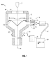
図1から2Cを参照し、まず図1を参照すると、外科手術処置での使用のための10と指定されるアクセス装置が示される。装置10とそれに関連する操作コンポーネントは、任意の適切な材料(例えば、生体適合性を有する材料)から形成され得る。アクセス装置10は、長手方向の軸“A”を規定し、ハウジング2およびアクセス部材4を含む。ハウジング2の近位端6は、開口8を含み、アクセス部材4は長手方向の通路12を規定する。開口8および長手方向の通路12は、処置に関連して使用される器具“I”のような外科手術物体の通過を可能にするために、長手方向の軸“A”に対して概して整列される。
With reference to FIGS. 1 to 2C, and referring first to FIG. 1, an access device designated 10 for use in a surgical procedure is shown. The
描写された実施形態では、アクセス装置10は、ハウジング2内に長手方向の通路12に隣接して配置される1つ以上の器具シール14を含む。器具シール14は、器具シール14を通して導入される器具“I”の周りに実質的に流体密のシールを作るように構成される。1つの適切な器具シールが本発明の譲受人であるRacenetに譲渡された米国特許番号6,702,787に開示され、この開示の全内容は、本明細書で参照により援用される。
In the depicted embodiment, the
ダックビルまたはゼロ閉鎖弁16は、長手方向の通路12内に配置され、ハウジング2と機械的共同作用関係にある。ゼロ閉鎖弁16は、図1に示されるように、密閉された構成で遠位に内部方向に先細りする。このため、ゼロ閉鎖弁16は、当該分野で従来的であるように、ゼロ閉鎖弁16を通して挿入された外科手術用器具“I”がない場合に実質的に流体密のシールを提供するように構成される。
A duckbill or zero
アクセス装置10は、1つ以上の適切なインターフェイスを介して加圧ガス“G”の源(図1)に接続するように適合される。描写された実施形態では、ホース“H”は、加圧ガスの源“G”にアクセス装置10を接続する。さらに詳細には、ホース“H”の遠位端は、加圧ガスの源“G”に操作可能に結合され、ホース“H”の近位端は、アクセス装置10に操作可能に結合する。さらに詳細には、ホース“H”の近位端は、1つ以上の適切な結合方法(例えば、ルアータイプの取り付けまたは同様のもの)を介して脱気制御メカニズム18に動作可能に結合する。
図2A−2Cを参照すると、本開示の実施形態に従った脱気制御メカニズム18(制御メカニズム18)が描写される。制御メカニズム18は、アクセス装置10に操作可能に結合し、外科手術処置中にアクセス装置10の脱気流を制御するように構成される。この目的で、制御メカニズム18は、長手方向の通路12と流体連絡関係にある弁20と、選択的に移動可能な機械インターフェイス26とを含む。
With reference to FIGS. 2A-2C, a deaeration control mechanism 18 (control mechanism 18) according to an embodiment of the present disclosure is depicted. The
弁20は、任意の適切な形状を有し得る。描写された実施形態では、弁20は、適切な寸法の概ね細長い筒状の形状を含む。弁20は、1つ以上の適切な固定方法(例えば、プレスばめ、摩擦適合、バヨネット型の嵌め合い、一体形成、または超音波溶接/熱溶接など)を介してアクセス装置10に操作可能に固定され得る。描写された実施形態では、弁20は、アクセス装置10と一体的に形成される。弁20は、ホース“H”がアクセス装置10にリムーバブルに固定され得るように寸法付けされ構成される。図2A−2Cで描写された実施形態では、弁20の一部分は、1つ以上のねじ山22を含む。ねじ山22は、当該分野で“ルアーロック”構成と一般的に呼ばれるものを提供する。あるいは、弁20は、ねじ山20を含まないときがあり、この弁20の構成は一般的に当該分野で“ルアースリップ”構成(例えば、図3A−図3C参照)と呼ばれる。これらのいずれのルアー構成もホース“H”の近位端と弁20とを単純で簡単な態様で結合することを容易にする。
The
適切な寸法の1つ以上の開口24が、弁20の長さに沿って操作可能に配置される。描写された実施形態では、1つの開口24が弁20の一面の長さに沿って操作可能に配置される。特定の実施形態では、2つの開口24が弁20の反対側に操作可能に配置され得る。開口24は、任意の適切な形状を有し得る。さらに詳細には、開口24は、円形、矩形、楕円形、および正方形から成るグループから選択される形状を有し得る。描写された実施形態では、開口24は、長さ“L”と幅“W”とにより規定される概ね矩形の形状を有する(図1)。脱気流は、開口24の所望の長さ“L”および“W”を露出することにより制御される。さらに詳細には、脱気流は、開口24の露出された領域に直接関連する。すなわち、開口24が多く露出されるほど脱気流の量が多い。
One or
脱気流を制御するために、制御メカニズム18は、アクセス装置10に操作可能に結合された選択的に移動可能な機械インターフェイス26を含む。さらに詳細には、選択的に移動可能な機械インターフェイス26は、弁20と操作可能に結合され、開口24と操作連絡関係にある。選択的に移動可能な機械インターフェイス26は、弁20の長さに沿い開口24にわたって動かされるときに、脱気流を制御および/または変更するように構成される。選択的に移動可能な機械インターフェイス26は、開口24を通した脱気流が必要でないときに(完全にでなければ)実質的に開口24を覆うように寸法付けされ形づけられる。
In order to control de-air flow, the
図2A−2Cに描写される実施形態では、選択的に移動可能な機械インターフェイス26は、弁20に可動的に結合されるキャップ26の形式を取る。さらに詳細には、キャップ26は、弁20に配置されたねじ山22と回転可能に結合するように構成された適量の対応するスロット(図示なし)を含む。ねじ山22およびスロットのこの構成は、キャップ26が弁20に回転されること、または“ねじられる”ことを可能にする。キャップ26は、弁20に結合されたときに、キャップ26が回されるにつれ、キャップ26が弁20の長さおよび開口24にわたって動くように(例えば時計回り、反時計回りの方向に)回るように構成される。描写された実施形態では、キャップ26の時計回りの回転は、キャップ26を弁20および開口24にわたって遠位に動かせ、反時計回りの回転は、キャップ26を弁20および開口24にわたって近位に動かせる。キャップ26および弁20は、キャップ26の時計回りの回転が、キャップ26を弁20および開口24にわたって近位に動かせ、反時計周りの回転が、キャップ26を弁20および開口24にわたって遠位に動かせるように構成され得ることが認識される。本開示に従って、脱気流は、開口24を覆うおよび/または露出するように、それぞれ、ゆるくすること(キャップ26を反時計回りに回転する)または締めること(キャップ26を時計回りに回転すること)により調整/制御される。特定の実施形態では、キャップ26が弁20の最も遠位の位置にあるとき、開口24は完全に覆われ(図2B)、キャップ26が最も近位の位置にある(または弁20に結合されていない(図2A))とき、開口は完全に露出される。
In the embodiment depicted in FIGS. 2A-2C, the selectively movable
特定の実施形態では、キャップ26の外表面は、キャップ26の回転を容易にするために、テクスチャをつけられ得る(例えば、節付けされる)。
In certain embodiments, the outer surface of the
描写された実施形態では、キャップ26は、1つ以上の適切な装置を介してアクセス装置10に操作可能に結合する。さらに詳細には、コード28の形式を取る、適切な材料から生成された繋ぎ縄が、1つ以上の適切な結合方法を介して、アクセス装置10にキャップ26を操作可能に結合する。例えば、図2A−2Cに示されるように、コード28は、キャップ26に1つ以上の適切な接着剤(例えば、熱硬化エポキシ)を介して結合され、1つ以上のタイプの結び目構成を介してアクセス装置10の周りにアクセス部材4に近接して結ばれるおよび/または巻きつけられる。この態様でキャップ26をアクセス装置10に結合することは、キャップ26が弁20に結合されていないときに、キャップ26を置き忘れする可能性または紛失の可能性を低減する。特定の場面では、結び目および/またはループの一部は、アクセス部材4および/またはアクセス装置10に操作可能に関連付けされる窪みまたは戻り止め構成を介してアクセス部材4に対して位置を維持され得る。
In the depicted embodiment, the
図3Aおよび3Cを参照すると、制御メカニズム18の別の実施形態が118を指定されて示される。制御メカニズム118は、実質的に制御メカニズム18と同様であり、本開示を重複する情報をもって不明瞭にしないように、アクセス装置10’に対する制御メカニズム118に特有である特徴のみがさらに詳細に記述される。
With reference to FIGS. 3A and 3C, another embodiment of the
選択的に移動可能な機械インターフェイス26’は、適切な材料から生成される概ね細長いプラグまたはストッパ126の形式を取る。1つの特定の実施形態では、プラグ126は、エラストマー材料(例えばゴム)から生成される。プラグ126は、プラグ126が弁20に“引き込まれる”もしくは“押し込まれる”か、または弁20から取り除かれるように弁20に可動的に位置するような寸法および大きさを有する。この目的のために、プラグ126は、弁20内に可動的に位置するように構成される遠位本体部分128(図3A)と、開口24が完全に閉鎖される(または“遮断”される)ように、弁20内の所定の位置にプラグが“押し込まれた”ときに、弁20の一部に接触するように構成される近位フランジまたは頭部130とを含む。フランジ130は、ユーザが掴むための表面を提供する。さらに、フランジ130は、プラグ126が弁24に完全に詰め込まれるか、または“押し込まれる”ことを防止する。
The selectively movable mechanical interface 26 'takes the form of a generally elongated plug or
プラグ126(またはその一部、例えば遠位本体部128)は、遠位部が弁20に挿入されるときに弁20に対してプラグ126を“押し込むこと”および/または“引き込むこと”を容易にするために、潤滑材料でコーティングされ得るか、または潤滑材料で生成され得る。プラグ126のコーティング、または生成に使用され得る1つの潤滑材料のタイプの1つは、テトラフルオロエチレンであり、一般的にTEFLON(登録商標)として当該分野で呼ばれ、その登録商標の下で販売されている。
Plug 126 (or part thereof, eg, distal body portion 128) facilitates “pushing” and / or “retracting”
プラグ126は、キャップ26に関して上記されたように繋留され得る。 Plug 126 can be anchored as described above with respect to cap 26.
図2A−2Cを参照すると、キャップ26の形式を取る選択的に移動可能な機械インターフェイス26を含む制御メカニズム18を有するアクセス装置10の使用方法が記述される。アクセス装置10は、組織の小さな切開口を通して腹部の内部に堅固に位置づけされる。キャップ26が弁20に接続されていないとき(図2A)に、ホース“H”は弁20に結合され、1つ以上の適切なタイプのガス(例えば、二酸化炭素)を使用して腹腔が吹送され、その結果気腹をもたらす。次に、ホース“H”は弁20から接続を外され、キャップ26が弁20に結合され、開口24がキャップ26により覆われる(図2B)まで、例えば時計回りに回される。注意すべきは、ホース“H”が弁20に接続されていないとき、少量のガスが弁20から漏れ出ることである。腹腔内のガスが排除および/または排出される必要がある場合、開口24、またはその一部が露出される(図2C)ようにキャップ26が弁20に沿って近位に移動するようにキャップ26が、例えば反時計回りに回される。開口24が完全にまたは部分的に露出されるとき、ガスは、所望の量のガスが腹腔から排除および/または排出されるまで開口24から流出することが可能である。
With reference to FIGS. 2A-2C, a method of using an
図3A−3Cを参照すると、プラグ126の形式を取る選択的に移動可能な機械インターフェイス126を含む制御メカニズム118を有するアクセス装置10’の使用方法が記述される。アクセス装置10’は、組織の小さな切開口を通して腹部の内部に堅固に位置づけされる。プラグ126が弁20に接続されていないとき(図3A)に、ホース“H”は弁20に結合され、1つ以上の適切なタイプのガス(例えば、二酸化炭素)を使用して腹腔に吹送され、その結果気腹をもたらす。次に、ホース“H”は弁20から接続を外され、プラグ126が弁20に結合され、開口24がプラグ126により閉鎖または“遮断される”(図3B)まで弁20にわたって遠位に“押し込まれる”。注意すべきは、ホース“H”が弁20に接続されていないとき、少量のガスが弁20から漏れ出ることである。腹腔内のガスが放出される必要がある場合、開口24、またはその一部が露出される(図3C)ようにプラグ126が弁20にそって近位に移動するように“引っ張られる”。開口24が完全にまたは部分的に露出されるとき、ガスは、所望の量のガスが腹腔から放出されるまで開口24から流出することが可能である。
With reference to FIGS. 3A-3C, a method of using an access device 10 'having a
前述の記載および様々な図面への参照から、また、特定の改変が、本発明の範囲から逸脱することなく本開示にされ得ることが当業者に認識される。例えば、図2A−2Cに示されるキャップ26および弁20は、プレスばめ、摩擦適合、または本明細書に記述された意図される目的に適切である他の適切な係合方法を介して互いに係合可能であり得ることが考慮される。この場面では、キャップ26は、プラグ126と同様に構成される。プラグ126と比較されるとき、弁20にわたってスライドするように構成されるキャップ26を際立たせるファクターは、キャップ26が弁20にわたって開口24の上をスライドするように構成されることである。
Those skilled in the art will recognize from the foregoing description and reference to the various figures and that certain modifications may be made to the present disclosure without departing from the scope of the invention. For example, the
特定の場面では、制御メカニズム18/118のいずれかをホース“H”の遠位端に操作可能に関連付けすることが有用であるとされ得ることが考慮される。例えば、制御メカニズム18は、ホース“H”の遠位端に操作可能に結合され得る。この場面では、制御メカニズム18は、吹送流および脱気流の双方を制御するように構成され得る。
It is contemplated that in certain situations it may be useful to operatively associate any of the
特定の場面では、ホース“H”の遠位端と、選択的に移動可能な機械インターフェイス(例えば、キャップ26/プラグ126)とを互いにリムーバブルに結合させることが有用とされ得ることが考慮される。さらに詳細には、ホース“H”の遠位端は、キャップ26/プラグ126を介して、1つ以上の前に記述された結合方法(例えば“ルアーロック”)を介して、弁20にリムーバブルに、堅固に接合するように構成され得る。
In certain situations, it is contemplated that it may be useful to connect the distal end of hose “H” and a selectively movable mechanical interface (eg,
本開示の範囲は、当該分野が許す限り広く、明細書がそのように解釈されることが意図されるため、本開示のいくつかの実施形態が本明細書に図面で示され(および/または)論考されたが、本開示はそれらに制限されることが意図されていない。そのため、上記は制限的に解釈されるものでなく、単に実施形態の例示化である。当業者は、ここに添付される特許請求の範囲および精神内の他の改変に想到する。 Since the scope of the present disclosure is as broad as the field permits, and the specification is intended to be interpreted as such, some embodiments of the present disclosure are shown in the drawings herein (and / or). Although discussed, this disclosure is not intended to be limited thereto. As such, the above is not to be construed as limiting, but merely an illustration of an embodiment. Those skilled in the art will envision other modifications within the scope and spirit of the claims appended hereto.
2 ハウジング
4 アクセス部材
8 開口
10 アクセス装置
12 長手方向の通路
A 長手方向の軸
I 器具
2
Claims (19)
該外科手術用器具の通過を可能にするために、該アクセス部材の長手方向の通路と連絡関係にある開口を規定する近位端を含むハウジングと、
該長手方向の通路内に配置されたゼロ閉鎖弁であって、該ゼロ閉鎖弁を通って挿入される該外科手術用器具がない場合に実質的に流体密のシールを提供するように構成されたゼロ閉鎖弁と、
該アクセス装置に操作可能に結合され、該アクセス装置の脱気流を制御するように構成された制御メカニズムであって、該制御メカニズムは、該長手方向の通路と流体連絡関係にある細長い弁を含み、該細長い弁は、該弁の長さに沿って操作可能に配置された少なくとも1つの開口を含み、該制御メカニズムは、該弁に操作可能に結合され、該少なくとも1つの開口と操作的連絡関係にある選択的に移動可能な機械インターフェイスを含み、該選択的に移動可能な機械インターフェイスは、該弁の長さに沿って動くときに脱気流を変更するように構成される、制御メカニズムと
を含む、外科手術処置での使用のためのアクセス装置。 An access member defining a longitudinal axis and having a longitudinal passage, the longitudinal passage allowing passage of a surgical instrument used to perform a surgical procedure Adapted to the access member;
A housing including a proximal end defining an opening in communication with a longitudinal passage of the access member to allow passage of the surgical instrument;
A zero closure valve disposed in the longitudinal passage and configured to provide a substantially fluid tight seal in the absence of the surgical instrument inserted through the zero closure valve. A zero closing valve,
A control mechanism operably coupled to the access device and configured to control degassing of the access device, the control mechanism including an elongated valve in fluid communication with the longitudinal passage The elongate valve includes at least one opening operably disposed along a length of the valve, and the control mechanism is operably coupled to the valve and is in operative communication with the at least one opening. A control mechanism comprising a selectively movable machine interface in relation, wherein the selectively moveable machine interface is configured to change deaeration as it moves along the length of the valve; An access device for use in a surgical procedure, including:
該外科手術用器具の通過を可能にするために、該アクセス部材の長手方向の通路と連絡関係にある開口を規定する近位端を含むハウジングと、
該アクセス装置と作動可能に関連付けされたゼロ閉鎖弁であって、該ゼロ閉鎖弁を通って挿入される該外科手術用器具がない場合に実質的に流体密のシールを提供するように構成された該ゼロ閉鎖弁と、
該アクセス装置の脱気流を制御するように構成された制御メカニズムであって、該制御メカニズムは、該長手方向の通路と流体的連絡関係にある弁を含み、該弁は、少なくとも1つの開口と、該弁に操作可能に結合された選択的に移動可能な機械インターフェイスとを含み、選択的に移動可能な機械インターフェイスは、弁の長さに沿って移動されるときに脱気流を変更するように構成される、制御メカニズムと
を含む、外科手術処置での使用のためのアクセス装置。 An access member defining a longitudinal axis and having a longitudinal passage, the longitudinal passage allowing passage of a surgical instrument used to perform a surgical procedure Adapted to the access member;
A housing including a proximal end defining an opening in communication with a longitudinal passage of the access member to allow passage of the surgical instrument;
A zero closure valve operably associated with the access device configured to provide a substantially fluid tight seal in the absence of the surgical instrument inserted through the zero closure valve The zero-closing valve;
A control mechanism configured to control deaeration of the access device, the control mechanism including a valve in fluid communication with the longitudinal passage, the valve comprising at least one opening and A selectively moveable machine interface operably coupled to the valve, the selectively moveable machine interface changing the de-air flow when moved along the length of the valve An access device for use in a surgical procedure, comprising a control mechanism.
Applications Claiming Priority (4)
| Application Number | Priority Date | Filing Date | Title |
|---|---|---|---|
| US41655910P | 2010-11-23 | 2010-11-23 | |
| US61/416,559 | 2010-11-23 | ||
| US13/192,712 US20120130178A1 (en) | 2010-11-23 | 2011-07-28 | Access apparatus including desufflation control mechanism |
| US13/192,712 | 2011-07-28 |
Publications (1)
| Publication Number | Publication Date |
|---|---|
| JP2012110676A true JP2012110676A (en) | 2012-06-14 |
Family
ID=44759614
Family Applications (1)
| Application Number | Title | Priority Date | Filing Date |
|---|---|---|---|
| JP2011196355A Withdrawn JP2012110676A (en) | 2010-11-23 | 2011-09-08 | Access apparatus including desufflation control mechanism |
Country Status (5)
| Country | Link |
|---|---|
| US (1) | US20120130178A1 (en) |
| EP (1) | EP2455021A2 (en) |
| JP (1) | JP2012110676A (en) |
| AU (1) | AU2011213771A1 (en) |
| CA (1) | CA2749452A1 (en) |
Families Citing this family (5)
| Publication number | Priority date | Publication date | Assignee | Title |
|---|---|---|---|---|
| ITBA20120020U1 (en) * | 2012-04-11 | 2013-10-12 | Vincenzo Nuzziello | "DOUBLE CHANNEL SURGICAL DEVICE FOR ABDOMINAL ACCESS" |
| US20160158468A1 (en) * | 2012-11-20 | 2016-06-09 | Surgiquest, Inc. | Systems and methods for conducting smoke evacuation during laparoscopic surgical procedures |
| CN109549691A (en) * | 2018-09-29 | 2019-04-02 | 江苏风和医疗器材股份有限公司 | Sealing element and puncture outfit for puncture outfit |
| CN109833081B (en) * | 2018-12-17 | 2020-05-26 | 江苏人冠医疗科技有限公司 | Gas filling and recycling system for laparoscopic surgery |
| WO2023133475A2 (en) * | 2022-01-05 | 2023-07-13 | Rl3T Llc | Adaptive and radially expanding speculum |
Family Cites Families (5)
| Publication number | Priority date | Publication date | Assignee | Title |
|---|---|---|---|---|
| US1617333A (en) * | 1925-06-06 | 1927-02-15 | Joseph L Hutchings | Drain device |
| US1723066A (en) * | 1927-10-08 | 1929-08-06 | Steel Drum Accessories Corp | Valve |
| ES2248897T3 (en) | 1997-05-02 | 2006-03-16 | United States Surgical Corporation | HERMETIC CLOSURE SYSTEM FOR TROCAR. |
| US20050209607A1 (en) * | 2004-03-22 | 2005-09-22 | John Lipchitz | Medical cannula assembly |
| US20090093682A1 (en) * | 2007-10-05 | 2009-04-09 | Tyco Healthcare Group Lp | Surgical portal with foam and fabric composite seal assembly |
-
2011
- 2011-07-28 US US13/192,712 patent/US20120130178A1/en not_active Abandoned
- 2011-08-16 CA CA2749452A patent/CA2749452A1/en not_active Abandoned
- 2011-08-18 AU AU2011213771A patent/AU2011213771A1/en not_active Abandoned
- 2011-09-08 JP JP2011196355A patent/JP2012110676A/en not_active Withdrawn
- 2011-09-09 EP EP11250755A patent/EP2455021A2/en not_active Withdrawn
Also Published As
| Publication number | Publication date |
|---|---|
| EP2455021A2 (en) | 2012-05-23 |
| US20120130178A1 (en) | 2012-05-24 |
| AU2011213771A1 (en) | 2012-06-07 |
| CA2749452A1 (en) | 2012-05-23 |
Similar Documents
| Publication | Publication Date | Title |
|---|---|---|
| JP5630860B2 (en) | Single incision surgical portal apparatus including an inner member | |
| US8574153B2 (en) | Flexible port seal | |
| JP5694675B2 (en) | Articulated surgical portal apparatus with spring | |
| JP5567867B2 (en) | Surgical portal device with movable housing | |
| JP2011167519A (en) | Access apparatus including integral zero-closure valve and check valve | |
| JP2012210402A (en) | Flexible sleeve having access port and attached cord | |
| JP2010207575A (en) | Access point including multi-layer seal and suture park | |
| JP2012110676A (en) | Access apparatus including desufflation control mechanism | |
| JP2014161733A (en) | Flexible access assembly | |
| JP2010518901A (en) | Flexible cannula with seal | |
| JP5607778B2 (en) | Surgical seal assembly | |
| JP2011092704A (en) | Surgical access assembly | |
| JP2010172694A (en) | Suture management system for surgical portal apparatus including internal tube | |
| US20100174143A1 (en) | Dual seal with bellows | |
| JP2010227576A (en) | Seal device with adjustable aperture | |
| JP2010527640A (en) | Flexible outer cannula sheath | |
| RU2656759C1 (en) | Trocar with fixation | |
| RU2485901C1 (en) | Trocar for fixation of hollow organ wall | |
| US10881391B2 (en) | Sealing pack assembly for use with endoscopic stitching device | |
| AU2009248457A1 (en) | Dual seal with bellows | |
| RU2269316C1 (en) | Endosurgical obturator for keeping instruments | |
| CA2731523A1 (en) | Portal apparatus with a tubular seal device |
Legal Events
| Date | Code | Title | Description |
|---|---|---|---|
| A300 | Application deemed to be withdrawn because no request for examination was validly filed |
Free format text: JAPANESE INTERMEDIATE CODE: A300 Effective date: 20141202 |