JP2012109035A - Connector - Google Patents
Connector Download PDFInfo
- Publication number
- JP2012109035A JP2012109035A JP2010254751A JP2010254751A JP2012109035A JP 2012109035 A JP2012109035 A JP 2012109035A JP 2010254751 A JP2010254751 A JP 2010254751A JP 2010254751 A JP2010254751 A JP 2010254751A JP 2012109035 A JP2012109035 A JP 2012109035A
- Authority
- JP
- Japan
- Prior art keywords
- terminal
- housing
- holder
- lance
- connector
- Prior art date
- Legal status (The legal status is an assumption and is not a legal conclusion. Google has not performed a legal analysis and makes no representation as to the accuracy of the status listed.)
- Granted
Links
Images


Classifications
-
- H—ELECTRICITY
- H01—ELECTRIC ELEMENTS
- H01R—ELECTRICALLY-CONDUCTIVE CONNECTIONS; STRUCTURAL ASSOCIATIONS OF A PLURALITY OF MUTUALLY-INSULATED ELECTRICAL CONNECTING ELEMENTS; COUPLING DEVICES; CURRENT COLLECTORS
- H01R13/00—Details of coupling devices of the kinds covered by groups H01R12/70 or H01R24/00 - H01R33/00
- H01R13/40—Securing contact members in or to a base or case; Insulating of contact members
- H01R13/42—Securing in a demountable manner
- H01R13/436—Securing a plurality of contact members by one locking piece or operation
- H01R13/4361—Insertion of locking piece perpendicular to direction of contact insertion
- H01R13/4362—Insertion of locking piece perpendicular to direction of contact insertion comprising a temporary and a final locking position
-
- H—ELECTRICITY
- H01—ELECTRIC ELEMENTS
- H01R—ELECTRICALLY-CONDUCTIVE CONNECTIONS; STRUCTURAL ASSOCIATIONS OF A PLURALITY OF MUTUALLY-INSULATED ELECTRICAL CONNECTING ELEMENTS; COUPLING DEVICES; CURRENT COLLECTORS
- H01R13/00—Details of coupling devices of the kinds covered by groups H01R12/70 or H01R24/00 - H01R33/00
- H01R13/40—Securing contact members in or to a base or case; Insulating of contact members
- H01R13/42—Securing in a demountable manner
- H01R13/436—Securing a plurality of contact members by one locking piece or operation
- H01R13/4364—Insertion of locking piece from the front
-
- H—ELECTRICITY
- H01—ELECTRIC ELEMENTS
- H01R—ELECTRICALLY-CONDUCTIVE CONNECTIONS; STRUCTURAL ASSOCIATIONS OF A PLURALITY OF MUTUALLY-INSULATED ELECTRICAL CONNECTING ELEMENTS; COUPLING DEVICES; CURRENT COLLECTORS
- H01R13/00—Details of coupling devices of the kinds covered by groups H01R12/70 or H01R24/00 - H01R33/00
- H01R13/40—Securing contact members in or to a base or case; Insulating of contact members
- H01R13/42—Securing in a demountable manner
- H01R13/422—Securing in resilient one-piece base or case, e.g. by friction; One-piece base or case formed with resilient locking means
- H01R13/4223—Securing in resilient one-piece base or case, e.g. by friction; One-piece base or case formed with resilient locking means comprising integral flexible contact retaining fingers
-
- H—ELECTRICITY
- H01—ELECTRIC ELEMENTS
- H01R—ELECTRICALLY-CONDUCTIVE CONNECTIONS; STRUCTURAL ASSOCIATIONS OF A PLURALITY OF MUTUALLY-INSULATED ELECTRICAL CONNECTING ELEMENTS; COUPLING DEVICES; CURRENT COLLECTORS
- H01R13/00—Details of coupling devices of the kinds covered by groups H01R12/70 or H01R24/00 - H01R33/00
- H01R13/46—Bases; Cases
- H01R13/502—Bases; Cases composed of different pieces
- H01R13/506—Bases; Cases composed of different pieces assembled by snap action of the parts
-
- H—ELECTRICITY
- H01—ELECTRIC ELEMENTS
- H01R—ELECTRICALLY-CONDUCTIVE CONNECTIONS; STRUCTURAL ASSOCIATIONS OF A PLURALITY OF MUTUALLY-INSULATED ELECTRICAL CONNECTING ELEMENTS; COUPLING DEVICES; CURRENT COLLECTORS
- H01R9/00—Structural associations of a plurality of mutually-insulated electrical connecting elements, e.g. terminal strips or terminal blocks; Terminals or binding posts mounted upon a base or in a case; Bases therefor
- H01R9/16—Fastening of connecting parts to base or case; Insulating connecting parts from base or case
-
- H—ELECTRICITY
- H01—ELECTRIC ELEMENTS
- H01R—ELECTRICALLY-CONDUCTIVE CONNECTIONS; STRUCTURAL ASSOCIATIONS OF A PLURALITY OF MUTUALLY-INSULATED ELECTRICAL CONNECTING ELEMENTS; COUPLING DEVICES; CURRENT COLLECTORS
- H01R11/00—Individual connecting elements providing two or more spaced connecting locations for conductive members which are, or may be, thereby interconnected, e.g. end pieces for wires or cables supported by the wire or cable and having means for facilitating electrical connection to some other wire, terminal, or conductive member, blocks of binding posts
- H01R11/11—End pieces or tapping pieces for wires, supported by the wire and for facilitating electrical connection to some other wire, terminal or conductive member
- H01R11/12—End pieces terminating in an eye, hook, or fork
-
- H—ELECTRICITY
- H01—ELECTRIC ELEMENTS
- H01R—ELECTRICALLY-CONDUCTIVE CONNECTIONS; STRUCTURAL ASSOCIATIONS OF A PLURALITY OF MUTUALLY-INSULATED ELECTRICAL CONNECTING ELEMENTS; COUPLING DEVICES; CURRENT COLLECTORS
- H01R13/00—Details of coupling devices of the kinds covered by groups H01R12/70 or H01R24/00 - H01R33/00
- H01R13/46—Bases; Cases
- H01R13/52—Dustproof, splashproof, drip-proof, waterproof, or flameproof cases
- H01R13/5219—Sealing means between coupling parts, e.g. interfacial seal
- H01R13/5221—Sealing means between coupling parts, e.g. interfacial seal having cable sealing means
-
- H—ELECTRICITY
- H01—ELECTRIC ELEMENTS
- H01R—ELECTRICALLY-CONDUCTIVE CONNECTIONS; STRUCTURAL ASSOCIATIONS OF A PLURALITY OF MUTUALLY-INSULATED ELECTRICAL CONNECTING ELEMENTS; COUPLING DEVICES; CURRENT COLLECTORS
- H01R2103/00—Two poles
-
- H—ELECTRICITY
- H01—ELECTRIC ELEMENTS
- H01R—ELECTRICALLY-CONDUCTIVE CONNECTIONS; STRUCTURAL ASSOCIATIONS OF A PLURALITY OF MUTUALLY-INSULATED ELECTRICAL CONNECTING ELEMENTS; COUPLING DEVICES; CURRENT COLLECTORS
- H01R2201/00—Connectors or connections adapted for particular applications
- H01R2201/26—Connectors or connections adapted for particular applications for vehicles
Landscapes
- Connector Housings Or Holding Contact Members (AREA)
Abstract
Description
本発明は、自動車用ワイヤーハーネス等に装着されるコネクタに関する。 The present invention relates to a connector to be mounted on an automobile wire harness or the like.
この種の従来例のコネクタとして図8及び図9に示すものがある。図8及び図9において、コネクタ100Aは、複数の端子101と、この各端子101を保持するハウジング110と、このハウジング110の外周に装着されるシェル120とを備えている。
As this type of conventional connector, there is one shown in FIGS. 8 and 9, the connector 100 </ b> A includes a plurality of
各端子101は、各電線Wの端部に固定されている。各端子101は、端子係止穴102を有する。各端子101は、ハウジング110の各端子キャビティ111に挿入によって配置されている。ハウジング110は、複数のハウジングランス112を有する。この各ハウジングランス112が各端子101の端子係止穴102に係止されている。各端子101は、ハウジングランス112の係止力によってハウジング110に保持されている。
Each
図10及び図11には他の従来例のコネクタが示されている(特許文献1参照)。図10及び図11において、コネクタ100Bは、複数の端子101と、この各端子101を保持するハウジング110と、このハウジング110の外周に装着されるシェル120とを備えている。
10 and 11 show another conventional connector (see Patent Document 1). 10 and 11, the connector 100 </ b> B includes a plurality of
各端子101は、各電線Wの端部に固定されている。各端子101は、端子係止穴102を有する。各端子101は、ハウジング110の各端子キャビティ111に挿入によって配置されている。ハウジング110は、複数のハウジングランス112を有する。この各ハウジングランス112が各端子101の端子係止穴102に係止されている。各端子101は、ハウジングランス112の係止力によってハウジング110に保持されている。ハウジング110は、上下一対のハウジング弾性アーム113を複数組有する。各組のハウジング弾性アーム113が各端子101を付勢している。各端子101は、端子キャビティ111内で上下一対のハウジング弾性アーム113の弾性力の均衡位置で位置保持されると共に、上下一対のハウジング弾性アーム113の弾性力に抗して端子キャビティ111内で上下方向に変移できる。
Each
ところで、前者の従来例にあっては、ハウジング110の端子キャビティ111の寸法は、部品寸法誤差、端子101の挿入性等を配慮して端子101の厚み寸法より少し大きく設定される。そのため、端子101がハウジングランス112に対して離脱する方向に変移可能である。端子101がハウジングランス112の離脱方向に変移すると、端子101がハウジングランス112の先端部、つまり、剪断面積が小さい箇所で係止され、これによりハウジングランス112の係止力が弱くなり、常に安定した所望の端子保持力が得られないという問題がある。
By the way, in the former conventional example, the dimension of the
特に、自動車用の高電流・高電圧用コネクタでは、接続される電線径が太いため、電線自体の剛性も非常に高い。すると、ワイヤーハーネスの屈曲により屈曲内周側と外周側で線長差ができ、これによって大きな引っ張り荷重が端子101とハウジング110間に作用する。従って、コネクタ100Aが常に安定した所望の端子保持力を有さないと、上記した引っ張り荷重でハウジングランス112が破損し、端子外れが発生することになる。ここで、ハウジングランス112の破損を防止するため、ハウジングランス112の先端側の剪断面積を確保する、ハウジングランス112の剛性自体を向上させる等の手段が考えられるが、スペース上、作業性上、コスト上等の問題が発生するため、実用的でなく採用できない。
In particular, in a high-current / high-voltage connector for automobiles, since the diameter of the wire to be connected is large, the rigidity of the wire itself is very high. Then, due to the bending of the wire harness, there is a difference in wire length between the bent inner peripheral side and the outer peripheral side, and thereby a large tensile load acts between the
また、後者の従来例にあっては、ハウジング110の端子キャビティ111内に突出する状態で一対のハウジング弾性アーム113が配置されるため、端子101を端子キャビティ111に挿入する際に、こじり等によってハウジング弾性アーム113を破損する可能性があるという問題がある。特に、後者の従来例にあっては、ハウジング110の端子キャビティ111の寸法は、端子101の厚み寸法に較べて前者の従来例より大きく設定される。そのため、ハウジング110の端子キャビティ111に端子101を挿入する際に、端子101の挿入方向が安定せず、こじり等によりハウジング弾性アーム113を破損する可能性が高い。
Further, in the latter conventional example, the pair of housing
そこで、本発明は、前記した課題を解決すべくなされたものであり、常に安定した所望の端子保持力が得られ、しかも、端子挿入時に弾性アームを破損する恐れもないコネクタを提供することを目的とする。 Accordingly, the present invention has been made to solve the above-described problems, and provides a connector that can always obtain a desired desired terminal holding force and that does not break the elastic arm when the terminal is inserted. Objective.
本発明は、端子係止穴を有する端子と、前記端子が挿入される端子キャビティを有し、前記端子キャビティに挿入された前記端子の前記端子係止穴に係止するハウジングランスを有するハウジングと、前記ハウジングに装着され、前記端子を前記ハウジングランスへの掛かり方向に付勢するホルダ弾性アームを有するホルダとを備えたことを特徴とする。 The present invention includes a terminal having a terminal locking hole, a housing having a terminal cavity into which the terminal is inserted, and a housing lance that locks into the terminal locking hole of the terminal inserted into the terminal cavity. And a holder having a holder elastic arm that is mounted on the housing and biases the terminal in a direction of engagement with the housing lance.
前記ホルダは、前記ホルダ弾性アームを支持するアーム支持部を有し、前記アーム支持部の反対側にホルダ係止部が設けられ、前記ホルダ係止部に前記ハウジングのハウジングロックアームが係止されることが好ましい。 The holder includes an arm support portion that supports the holder elastic arm, a holder locking portion is provided on the opposite side of the arm support portion, and a housing lock arm of the housing is locked to the holder locking portion. It is preferable.
前記端子は、ボルト締結穴を有するものを含む。 The terminal includes one having a bolt fastening hole.
本発明によれば、ホルダ弾性アームが端子をハウジングランスへの掛かり方向に付勢することから、端子がハウジングランスに対して離脱する方向に変移し難くいため、端子がハウジングランスの根本箇所、つまり、剪断面積が大きい箇所で係止するため、ハウジングランスの係止力が弱くなることがない。また、端子をハウジングの端子キャビティに挿入し、その後にホルダをハウジングに装着すれば、端子を端子キャビティに挿入する際に、端子によってホルダ弾性アームを破損する恐れがない。以上より、端子キャビティ内に常に安定した所望の端子保持力が得られ、しかも、端子挿入時に弾性アームを破損する恐れもないコネクタを提供できる。 According to the present invention, since the holder elastic arm urges the terminal in the direction in which the terminal is engaged with the housing lance, the terminal is difficult to change in the direction in which the terminal is detached from the housing lance. The locking force of the housing lance is not weakened because the locking is performed at a location where the shear area is large. Further, if the terminal is inserted into the terminal cavity of the housing and then the holder is mounted on the housing, the holder elastic arm is not damaged by the terminal when the terminal is inserted into the terminal cavity. As described above, it is possible to provide a connector that can always provide a desired desired terminal holding force in the terminal cavity and that does not break the elastic arm when the terminal is inserted.
以下、本発明の一実施形態を図面に基づいて説明する。 Hereinafter, an embodiment of the present invention will be described with reference to the drawings.
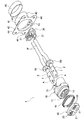
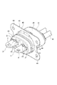
図1〜図7は本発明の一実施形態を示す。図1〜図7において、コネクタ1は、2つの端子2と、この2つの端子2が保持されたハウジング10と、ハウジング10の前方側に装着されたホルダであるフロントホルダ20と、ハウジング10の後方側に装着されたリアホルダ30と、ハウジング10の外周に配置されたシェル40と、このシェル40の更に外周に配置されたシールドリング45とを備えている。
1 to 7 show an embodiment of the present invention. 1 to 7, the
各端子2は、導体の金属より形成されている。各端子2は、端子係止穴3とボルト締結穴4をそれぞれ有する。端子係止穴3は、ハウジング10及びフロントホルダ20内の位置に形成されている。ボルト締結穴4は、フロントホルダ20より外側に突出する位置に形成されている。各端子2は、ボルト締結穴4を利用して取付側である筐体(図示せず)の端子台にボルト締結される。各端子2には、各電線Wの端部が加締めによって固定されている。各電線Wには、ゴム栓50がそれぞれ通されている。
Each
ハウジング10は、絶縁体の合成樹脂より形成されている。ハウジング10には、2つの端子キャビティ11が間隔を置いて設けられている。各端子キャビティ11に端子2が挿入によってそれぞれ配置されている。ハウジング10には、各端子キャビティ11に突出するハウジングランス12が設けられている。各ハウジングランス12が各端子2の端子係止穴3に係止されている。各端子2は、ハウジングランス12の係止力によって端子キャビティ11より引き抜き出来ないようハウジング10に固定されている。ハウジング10のフロント側には、ハウジングロックアーム13が複数箇所に設けられている。ハウジング10のリア側には、ハウジングロックアーム14とハウジング係止部15が複数箇所に設けられている。
The
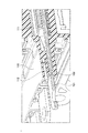
フロントホルダ20は、絶縁体の合成樹脂より形成されている。フロントホルダ20は、ハウジング10のフロント側にパッキン51を介在して装着されている。フロントホルダ20は、2つの端子貫通穴21を有する。この各端子貫通穴21より端子2がフロント側に突出している。フロントホルダ20には、ホルダ係止部22が複数箇所に設けられている。ホルダ係止部22にハウジングロックアーム13が係止している。これにより、フロントホルダ20は、ハウジング10にロックされている。フロントホルダ20には、2箇所に各一対のホルダ弾性アーム23が設けられている。各ホルダ弾性アーム23は、端子2をハウジングランス12への掛かり方向に弾性力F(図7に示す)によって付勢している。又、ホルダ弾性アーム23は、アーム支持部24によって支持されている。このアーム支持部24の反対側に上記したホルダ係止部22が設けられている。
The
フロントホルダ20には、各箇所のホルダ弾性アーム23に間隔を置いた位置にそれぞれ突部25が設けられている。突部25は、フロントホルダ20をハウジング10に装着する際に、ハウジングランス12が端子係止穴3に係止されていない状態では、ハウジングランス12の先端部に突き当たり、これ以上のフロントホルダ20の装着が阻止される。又、突部25は、フロントホルダ20をハウジング10に装着する際に、ハウジングランス12が端子係止穴3に係止された状態では、ハウジングランス12の先端部に突き当たることなく、フロントホルダ20の装着を許容する。そして、突部25は、フロントホルダ20のハウジング10への装着位置では、ハウジングランス12が端子係止穴3より離脱する方向に弾性変形できない位置に入り込む。つまり、突部25は、フロントホルダ20のハウジング10への装着過程では、ハウジングランス12の半嵌合検知機能を有し、フロントホルダ20のハウジング10への装着完了後には、ハウジングランス12の二重係止機能を有する。
The
パッキン51は、その各一部がハウジング10とフロントホルダ20の各周縁溝16,26にそれぞれはめ込まれた状態で配置されている。パッキン51は、ハウジング10と取付側である筐体(図示せず)間を止水する。
The packing 51 is arranged in a state in which each part thereof is fitted in the
リアホルダ30は、2つのゴム栓50と共にハウジング10の2つの端子キャビティ11に装着されている。リアホルダ30は、端子キャビティ11からの各ゴム栓50の脱落を防止している。各ゴム栓50は、電線Wとハウジング10間を止水している。リアホルダ30は、ヒンジ(図示せず)を介して連結された二分割部材であり、ヒンジを利用して電線Wの外周に装着されている。リアホルダ30は、上下一対のホルダロックアーム31を有する。この各ホルダロックアーム31が各ハウジング係止部15に係止されている。これにより、リアホルダ30は、ハウジング10にロックされている。
The
シェル40は、導体の金属より形成されている。シェル40は、ハウジング10が挿入される筒部41とこの筒部41より外側に突出するフランジ部42とを有する。筒部41には、シェル係止穴43が設けられている。このシェル係止穴43にハウジングロックアーム14が係止されている。これにより、シェル40は、ハウジング10にロックされている。フランジ部42には、四隅近くに締結穴44が設けられている。コネクタ1は、これら締結穴44を利用して取付側の筐体(図示せず)にボルト(図示せず)で固定される。
The
シールドリング45は、シェル40の筒部41上に編組電線(図示せず)の端部を介在して加締め固定されている。編組電線は、電線Wを被っている。つまり、編組電線は、シェル、筐体(図示せず)に固定するボルト(図示せず)、筐体(図示せず)によってアースされている。これにより、電線Wに高電圧の電流を流した際に発生する電磁波をシールドする。
The
次に、コネクタ1の組み付け手順を簡単に説明する。先ず、各電線Wにゴム栓50を通す。ゴム栓50を通した各電線Wの端部に各端子2を加締めによって固定する。
Next, a procedure for assembling the
次に、各端子2をハウジング10のリア側から端子キャビティ11に挿入する。端子2の先端がハウジングランス12に突き当たると、ハウジングランス12が弾性変形し、これにより端子2の挿入が許容される。端子2が挿入完了位置まで挿入されると、ハウジングランス12が端子2の端子係止穴3の位置に一致する。すると、ハウジングランス12が弾性復帰変形して端子2の端子係止穴3に係止される。これにより、端子2はハウジング2に固定される。又、この端子2の端子キャビティ11への挿入でゴム栓50も端子キャビティ11内に挿入される。
Next, each
次に、リアホルダ30をハウジング10のリア側より端子キャビティ11内に挿入する。リアホルダ30のホルダロックアーム31をハウジング10のハウジング係止部15に係止する。これにより、リアホルダ30がハウジング10に装着されると共にゴム栓50の脱落が防止される。
Next, the
次に、パッキン51をハウジング10のフロント側より挿入し、その後、フロントホルダ20をハウジング10のフロント側より挿入する。フロントホルダ20のホルダ係止部22にハウジング10のハウジングロックアーム13を係止する。これにより、フロントホルダ20がハウジング10に装着されると共にパッキン51の脱落が防止される。
Next, the packing 51 is inserted from the front side of the
次に、シェル40をハウジング10のリア側より挿入する。シェル40のシェル係止穴43にハウジング10のハウジングロックアーム14を係止する。これにより、シェル40がハウジング10に装着される。
Next, the
次に、電線Wの外周を被った編組電線(図示せず)の端部をシェル40の筒部41上に配置する。編組電線(図示せず)の上からシールドリング45を加締め固定する。これにより、シールドリング45と共に編組電線(図示せず)がシェル40に固定される。これで、組み付けが完了する。
Next, the end portion of the braided electric wire (not shown) covering the outer periphery of the electric wire W is disposed on the
以上説明したように、コネクタ1は、端子係止穴3を有する端子2と、端子2が端子キャビティ11に挿入され、端子2の端子係止穴3に係止するハウジングランス12を有するハウジング10と、ハウジング10に装着され、端子2をハウジングランス12への掛かり方向に付勢するホルダ弾性アーム23を有するフロントホルダ20とを備えている。従って、ホルダ弾性アーム23が端子2をハウジングランス12への掛かり方向に付勢することから、端子2がハウジングランス12に対して離脱する方向に変移し難くいため、端子2がハウジングランス12の根本箇所、つまり、剪断面積が大きい箇所で係止するため、ハウジングランス12の係止力が弱くなることがない。また、上記組み付け手順で説明したように、端子2をハウジング10の端子キャビティ11に挿入し、その後にフロントホルダ20をハウジング10に装着すれば、端子2を端子キャビティ11に挿入する際に、端子2によってホルダ弾性アーム23を破損する恐れがない。以上より、常に安定した所望の端子保持力が得られ、しかも、端子挿入時にホルダ弾性アーム23を破損する恐れもない。
As described above, the
また、従来例では、端子2の挿入に際して、ハウジング弾性アーム113の付勢力に抗して端子101を挿入する必要があり、高い挿入力が要求される可能性があった。しかし、本発明では、端子2の挿入に際してホルダ弾性アーム23からの付勢力が作用しないため、端子2を弱い挿入力で挿入でき、挿入作業性が向上するという利点もある。
Further, in the conventional example, when the
フロントホルダ20は、ホルダ弾性アーム23を支持するアーム支持部24を有し、アーム支持部24の反対側にホルダ係止部22が設けられ、ホルダ係止部22にハウジング10のハウジングロックアーム13が係止している。従って、ハウジング10のハウジングロックアーム13の付勢力がアーム支持部24に作用し、アーム支持部24がホルダ弾性アーム23の反力によって変移して端子2への付勢力が弱くなるという事態を防止できる。これにより、ホルダ弾性アーム23は、確実に安定した所望の付勢力を端子2に作用させる。
The
端子2は、ボルト締結穴4を有する。つまり、端子2には、ボルト締結に際して非常に大きな外力が掛かる恐れがある。その際に、端子2は、端子キャビティ11の隙間によって、ホルダ弾性アーム23の付勢力に抗して変移可能であるため、ボルト締結時の外力によって端子2やハウジング10が変形したり、損傷したりするような事態を極力防止できる。
The
フロントホルダ20は、フロントホルダ20をハウジング10に装着する際に、ハウジングランス12が端子係止穴3に係止されていない状態では、ハウジングランス12に干渉してフロントホルダ20の装着を阻止し、フロントホルダ20のハウジング10への装着位置では、ハウジングランス12が端子係止穴3より離脱する方向の弾性変形を阻止する突部25を有する。従って、ハウジングランス12が端子2に係止されていない状態でフロントホルダ20がハウジング10に装着されることを防止できる。又、フロントホルダ20がハウジング10に装着された後に、ハウジングランス12が端子係止穴3より離脱するという事態を防止できる。
When the
1 コネクタ
2 端子
3 端子係止穴
4 ボルト締結穴
10 ハウジング
11 端子キャビティ
12 ハウジングランス
13 ハウジングロックアーム
20 フロントホルダ(ホルダ)
22 ホルダ係止部
23 ホルダ弾性アーム
24 アーム支持部
1
22
Claims (3)
前記端子が挿入される端子キャビティを有し、且つ、前記端子キャビティに挿入された前記端子の前記端子係止穴に係止するハウジングランスを有するハウジングと、
前記ハウジングに装着され、前記端子を前記ハウジングランスへの掛かり方向に付勢するホルダ弾性アームを有するホルダとを備えたことを特徴とするコネクタ。 A terminal having a terminal locking hole;
A housing having a terminal cavity into which the terminal is inserted, and a housing lance that locks into the terminal locking hole of the terminal inserted into the terminal cavity;
And a holder having a holder elastic arm that is mounted on the housing and biases the terminal in a direction in which the terminal is engaged with the housing lance.
前記ホルダは、前記ホルダ弾性アームを支持するアーム支持部を有し、前記アーム支持部の反対側にホルダ係止部が設けられ、前記ホルダ係止部に前記ハウジングのハウジングロックアームが係止されたことを特徴とするコネクタ。 The connector according to claim 1,
The holder includes an arm support portion that supports the holder elastic arm, a holder locking portion is provided on the opposite side of the arm support portion, and a housing lock arm of the housing is locked to the holder locking portion. A connector characterized by that.
前記端子は、ボルト締結穴を有することを特徴とするコネクタ。 The connector according to claim 1 or 2, wherein
The connector has a bolt fastening hole.
Priority Applications (5)
| Application Number | Priority Date | Filing Date | Title |
|---|---|---|---|
| JP2010254751A JP5651436B2 (en) | 2010-11-15 | 2010-11-15 | connector |
| CN201180041203.XA CN103081243B (en) | 2010-11-15 | 2011-10-12 | Connector |
| US13/702,416 US8747157B2 (en) | 2010-11-15 | 2011-10-12 | Connector |
| PCT/JP2011/073368 WO2012066869A1 (en) | 2010-11-15 | 2011-10-12 | Connector |
| EP11841082.8A EP2642605B1 (en) | 2010-11-15 | 2011-10-12 | Connector |
Applications Claiming Priority (1)
| Application Number | Priority Date | Filing Date | Title |
|---|---|---|---|
| JP2010254751A JP5651436B2 (en) | 2010-11-15 | 2010-11-15 | connector |
Publications (2)
| Publication Number | Publication Date |
|---|---|
| JP2012109035A true JP2012109035A (en) | 2012-06-07 |
| JP5651436B2 JP5651436B2 (en) | 2015-01-14 |
Family
ID=46083810
Family Applications (1)
| Application Number | Title | Priority Date | Filing Date |
|---|---|---|---|
| JP2010254751A Active JP5651436B2 (en) | 2010-11-15 | 2010-11-15 | connector |
Country Status (5)
| Country | Link |
|---|---|
| US (1) | US8747157B2 (en) |
| EP (1) | EP2642605B1 (en) |
| JP (1) | JP5651436B2 (en) |
| CN (1) | CN103081243B (en) |
| WO (1) | WO2012066869A1 (en) |
Cited By (1)
| Publication number | Priority date | Publication date | Assignee | Title |
|---|---|---|---|---|
| US9431750B2 (en) | 2014-04-08 | 2016-08-30 | Yazaki Corporation | Connector |
Families Citing this family (21)
| Publication number | Priority date | Publication date | Assignee | Title |
|---|---|---|---|---|
| JP5751875B2 (en) * | 2011-03-22 | 2015-07-22 | 矢崎総業株式会社 | Shield connector |
| DE102012209298B4 (en) * | 2012-06-01 | 2017-10-05 | Te Connectivity Germany Gmbh | Electrical connector, connector assembly and method of mounting the connector |
| JP5522217B2 (en) * | 2012-08-21 | 2014-06-18 | 第一精工株式会社 | Electrical connector |
| JP6024991B2 (en) * | 2013-06-17 | 2016-11-16 | 住友電装株式会社 | Connectors and housings |
| JP6307691B2 (en) * | 2014-03-19 | 2018-04-11 | 株式会社オーディオテクニカ | Connector and connector manufacturing method |
| JP6452546B2 (en) * | 2015-05-20 | 2019-01-16 | 日本航空電子工業株式会社 | connector |
| JP6727580B2 (en) * | 2016-06-10 | 2020-07-22 | 日本圧着端子製造株式会社 | Connector terminal holding member, connector, and electrical connection device |
| JP6402145B2 (en) * | 2016-07-13 | 2018-10-10 | 矢崎総業株式会社 | connector |
| US9954347B1 (en) * | 2017-06-19 | 2018-04-24 | Delphi Technologies, Inc. | Wire harness assembly and seal retainer therefore |
| US10477717B2 (en) | 2017-09-29 | 2019-11-12 | Yazaki North America, Inc. | Self-aligning busbar assembly |
| US11339823B2 (en) | 2018-08-09 | 2022-05-24 | J.S.T. Corporation | System and method for sealing a metal fastener from electrolyte in an area of dissimilar metals |
| US10819073B2 (en) | 2018-12-04 | 2020-10-27 | J.S.T. Corporation | High voltage connector and method for assembling thereof |
| JP7460542B2 (en) * | 2019-02-08 | 2024-04-02 | ジェイエスティー コーポレーション | Electromagnetic interference (EMI) ground fault protection method for connectors using conductive housings |
| JP7115349B2 (en) * | 2019-02-11 | 2022-08-09 | 住友電装株式会社 | connector |
| US10923860B2 (en) * | 2019-02-25 | 2021-02-16 | J.S.T. Corporation | Method for shielding and grounding a connector assembly from electromagnetic interference (EMI) using conductive seal and conductive housing |
| US10804655B2 (en) | 2019-02-28 | 2020-10-13 | J.S.T. Corporation | Method for electromagnetic interference (EMI) protection for a connector assembly using a conductive seal |
| US10923837B2 (en) * | 2019-06-04 | 2021-02-16 | Ford Global Technologies, Llc | Terminal block with sealing terminal lug |
| JP7005118B2 (en) * | 2019-07-29 | 2022-01-21 | 矢崎総業株式会社 | connector |
| JP7155208B2 (en) * | 2020-08-13 | 2022-10-18 | 矢崎総業株式会社 | connector |
| JP7155207B2 (en) * | 2020-08-13 | 2022-10-18 | 矢崎総業株式会社 | connector |
| JP7174027B2 (en) * | 2020-11-18 | 2022-11-17 | 矢崎総業株式会社 | connector |
Citations (4)
| Publication number | Priority date | Publication date | Assignee | Title |
|---|---|---|---|---|
| JPH03116672A (en) * | 1989-09-29 | 1991-05-17 | Amp Japan Ltd | Electric connector |
| JPH08241749A (en) * | 1994-12-08 | 1996-09-17 | Molex Inc | Connector with leading edge installation type terminal locating guarantee device |
| JP2003100377A (en) * | 2001-09-26 | 2003-04-04 | Sumitomo Wiring Syst Ltd | Connector |
| JP2009211976A (en) * | 2008-03-05 | 2009-09-17 | Yazaki Corp | Connector |
Family Cites Families (6)
| Publication number | Priority date | Publication date | Assignee | Title |
|---|---|---|---|---|
| JP2547381Y2 (en) * | 1992-07-28 | 1997-09-10 | 矢崎総業株式会社 | Multi-pole connector |
| JP2635486B2 (en) * | 1992-08-25 | 1997-07-30 | 矢崎総業株式会社 | connector |
| US5951332A (en) * | 1999-01-07 | 1999-09-14 | Wang; Jen-Ching | Electric female connector for use in a caravan |
| KR101000152B1 (en) | 2002-09-25 | 2010-12-10 | 미츠비시 덴센 고교 가부시키가이샤 | Electrical connector |
| JP4523403B2 (en) * | 2004-12-28 | 2010-08-11 | 三菱電線工業株式会社 | Electrical connector |
| JP5508927B2 (en) * | 2010-04-22 | 2014-06-04 | 日本航空電子工業株式会社 | Connector and waterproof connector |
-
2010
- 2010-11-15 JP JP2010254751A patent/JP5651436B2/en active Active
-
2011
- 2011-10-12 US US13/702,416 patent/US8747157B2/en active Active
- 2011-10-12 EP EP11841082.8A patent/EP2642605B1/en active Active
- 2011-10-12 CN CN201180041203.XA patent/CN103081243B/en active Active
- 2011-10-12 WO PCT/JP2011/073368 patent/WO2012066869A1/en active Application Filing
Patent Citations (4)
| Publication number | Priority date | Publication date | Assignee | Title |
|---|---|---|---|---|
| JPH03116672A (en) * | 1989-09-29 | 1991-05-17 | Amp Japan Ltd | Electric connector |
| JPH08241749A (en) * | 1994-12-08 | 1996-09-17 | Molex Inc | Connector with leading edge installation type terminal locating guarantee device |
| JP2003100377A (en) * | 2001-09-26 | 2003-04-04 | Sumitomo Wiring Syst Ltd | Connector |
| JP2009211976A (en) * | 2008-03-05 | 2009-09-17 | Yazaki Corp | Connector |
Cited By (1)
| Publication number | Priority date | Publication date | Assignee | Title |
|---|---|---|---|---|
| US9431750B2 (en) | 2014-04-08 | 2016-08-30 | Yazaki Corporation | Connector |
Also Published As
| Publication number | Publication date |
|---|---|
| EP2642605B1 (en) | 2016-09-14 |
| CN103081243A (en) | 2013-05-01 |
| CN103081243B (en) | 2015-04-08 |
| US8747157B2 (en) | 2014-06-10 |
| US20130078872A1 (en) | 2013-03-28 |
| EP2642605A4 (en) | 2014-04-02 |
| EP2642605A1 (en) | 2013-09-25 |
| JP5651436B2 (en) | 2015-01-14 |
| WO2012066869A1 (en) | 2012-05-24 |
Similar Documents
| Publication | Publication Date | Title |
|---|---|---|
| JP5651436B2 (en) | connector | |
| US9385516B2 (en) | Connector | |
| US8808026B2 (en) | Waterproof structure | |
| JP6024991B2 (en) | Connectors and housings | |
| JP5314540B2 (en) | connector | |
| US9455525B2 (en) | Connector with flexible conductive member to isolate terminal from vibrations in a wire | |
| US8469751B2 (en) | Electrical connector and harness | |
| JP2009038032A (en) | Power distribution module | |
| TWM488766U (en) | Plugging/connecting device | |
| JP2013101856A (en) | Joint connector | |
| JP3827650B2 (en) | Shield connection structure | |
| WO2012157503A1 (en) | Waterproof connector | |
| EP3402008B1 (en) | Waterproof structure of connector | |
| EP3046185A1 (en) | Connector | |
| US20140017929A1 (en) | Connector | |
| JP4116939B2 (en) | Conductive path | |
| JP2014060073A (en) | Connector | |
| JP2012109031A (en) | Connector | |
| JP2006296050A (en) | Corrugated clamp | |
| KR200448593Y1 (en) | Connector | |
| JP2011165328A (en) | Connector | |
| KR200442919Y1 (en) | A connector | |
| JP2006236899A (en) | Terminal fitting for connector | |
| CN113904162B (en) | Connector with a plurality of connectors | |
| CN220306558U (en) | Male connector |
Legal Events
| Date | Code | Title | Description |
|---|---|---|---|
| A621 | Written request for application examination |
Free format text: JAPANESE INTERMEDIATE CODE: A621 Effective date: 20131017 |
|
| A521 | Request for written amendment filed |
Free format text: JAPANESE INTERMEDIATE CODE: A523 Effective date: 20131106 |
|
| A131 | Notification of reasons for refusal |
Free format text: JAPANESE INTERMEDIATE CODE: A131 Effective date: 20140916 |
|
| A521 | Request for written amendment filed |
Free format text: JAPANESE INTERMEDIATE CODE: A523 Effective date: 20141020 |
|
| TRDD | Decision of grant or rejection written | ||
| A01 | Written decision to grant a patent or to grant a registration (utility model) |
Free format text: JAPANESE INTERMEDIATE CODE: A01 Effective date: 20141111 |
|
| A61 | First payment of annual fees (during grant procedure) |
Free format text: JAPANESE INTERMEDIATE CODE: A61 Effective date: 20141117 |
|
| R150 | Certificate of patent or registration of utility model |
Ref document number: 5651436 Country of ref document: JP Free format text: JAPANESE INTERMEDIATE CODE: R150 |
|
| R250 | Receipt of annual fees |
Free format text: JAPANESE INTERMEDIATE CODE: R250 |
|
| R250 | Receipt of annual fees |
Free format text: JAPANESE INTERMEDIATE CODE: R250 |
|
| R250 | Receipt of annual fees |
Free format text: JAPANESE INTERMEDIATE CODE: R250 |
|
| R250 | Receipt of annual fees |
Free format text: JAPANESE INTERMEDIATE CODE: R250 |
|
| R250 | Receipt of annual fees |
Free format text: JAPANESE INTERMEDIATE CODE: R250 |
|
| R250 | Receipt of annual fees |
Free format text: JAPANESE INTERMEDIATE CODE: R250 |
|
| S531 | Written request for registration of change of domicile |
Free format text: JAPANESE INTERMEDIATE CODE: R313531 |
|
| R350 | Written notification of registration of transfer |
Free format text: JAPANESE INTERMEDIATE CODE: R350 |
|
| R250 | Receipt of annual fees |
Free format text: JAPANESE INTERMEDIATE CODE: R250 |