JP2012108317A - Image forming apparatus - Google Patents
Image forming apparatus Download PDFInfo
- Publication number
- JP2012108317A JP2012108317A JP2010257055A JP2010257055A JP2012108317A JP 2012108317 A JP2012108317 A JP 2012108317A JP 2010257055 A JP2010257055 A JP 2010257055A JP 2010257055 A JP2010257055 A JP 2010257055A JP 2012108317 A JP2012108317 A JP 2012108317A
- Authority
- JP
- Japan
- Prior art keywords
- region
- developer
- roughness
- developing sleeve
- photosensitive drum
- Prior art date
- Legal status (The legal status is an assumption and is not a legal conclusion. Google has not performed a legal analysis and makes no representation as to the accuracy of the status listed.)
- Granted
Links
Images


Landscapes
- Dry Development In Electrophotography (AREA)
- Cleaning In Electrography (AREA)
Abstract
【課題】 コストアップを招来せずに、クリーニングブレードが有するクリーニング性能の耐久性を向上させることができる画像形成装置を提供する。
【解決手段】 感光体ドラム11と、現像スリーブ3と、ブレード19aと、を備え、現像スリーブ3は、感光体ドラム11の画像形成領域と対向する画像形成幅領域Aよりも外側に位置する第1領域Bと、第1領域Bよりも外側に位置する第2領域Cと、を有し、第1領域Bは、現像スリーブ3の周方向で、少なくとも第1粗さを有する第1粗さ領域X、及び、第1粗さよりも粗さが小さい第2粗さを有する第2粗さ領域Yを有し、第1粗さ領域Xでは現像剤を担持し、ブレード19aの先端は、画像形成幅領域Aから第2領域Cまでに亘る現像スリーブ3の表面に対応する感光体ドラム11の表面部位に対向して配置される画像形成装置100を構成した。
【選択図】 図4PROBLEM TO BE SOLVED: To provide an image forming apparatus capable of improving the durability of the cleaning performance of a cleaning blade without causing an increase in cost.
A photosensitive drum 11, a developing sleeve 3, and a blade 19a are provided. The developing sleeve 3 is positioned outside an image forming width area A that faces an image forming area of the photosensitive drum 11. 1 region B and a second region C located outside the first region B, and the first region B has at least a first roughness in the circumferential direction of the developing sleeve 3. There is a region X and a second roughness region Y having a second roughness that is smaller than the first roughness. The first roughness region X carries a developer, and the tip of the blade 19a The image forming apparatus 100 is configured so as to face the surface portion of the photosensitive drum 11 corresponding to the surface of the developing sleeve 3 extending from the formation width region A to the second region C.
[Selection] Figure 4
Description
本発明は、像担持体の表面の静電像を現像剤で現像する現像装置、及び、像担持体の表面の残トナーをクリーニングするクリーニング装置を備える画像形成装置に関する。 The present invention relates to a developing device that develops an electrostatic image on the surface of an image carrier with a developer, and an image forming apparatus that includes a cleaning device that cleans residual toner on the surface of the image carrier.
従来、像担持体の残トナーをクリーニングするクリーニング装置を備える画像形成装置に関する発明として、特許文献1及び特許文献2に記載の発明が開示されている。
Conventionally, the inventions disclosed in
特許文献1に記載の発明は、クリーニングブレード、及び、クリーニングブレードよりも像担持体の回転方向の上流側に配置されたブラシローラを有するクリーニング装置を備える画像形成装置に関する発明である。このした構成によれば、残トナーの除去性能が向上し、像担持体の表面やクリーニングブレードの先端の磨耗が減少する旨特許文献1に記載されている。
The invention described in
特許文献2に記載の発明は、クリーニングブレードの長手方向の端部のみにイソシアネート化合物を含浸させる画像形成装置に関する発明である。こうした構成によれば、クリーニング部材のクリーニング性能が維持され、クリーニングブレードの捲れが抑制される旨記載されている。
The invention described in
しかしながら、特許文献1に記載の発明では、ブラシローラが像担持体の表面を摺る場合に、トナーや外添剤の融着が発生し、クリーニングブレードの耐久性が低下する虞があった。また、ブラシローラを組み込むスペース的問題、部品点数の増加によるコストアップ等の問題等も、安易に導入できない理由となる。
However, in the invention described in
また、特許文献2に記載の発明では、クリーニングブレードの長手方向の端部を低摩擦係数化するとしても処理工程が増すことでコストアップに繋がる。また、処理端及び未処理端の境界で摩擦係数の変動が大きくなり、クリーニング性能の不具合が発生する虞もある。
Further, in the invention described in
本発明は、上記実情に鑑み、コストアップを招来せずに、クリーニングブレードが有するクリーニング性能の耐久性を向上させることができる画像形成装置を提供することを課題とする。 In view of the above circumstances, an object of the present invention is to provide an image forming apparatus capable of improving the durability of the cleaning performance of a cleaning blade without incurring an increase in cost.
上記課題を解決するために、本発明の画像形成装置は、像担持体と、前記像担持体の軸と平行な方向に延び、前記像担持体の表面の静電像を現像剤で現像する現像剤担持体と、前記像担持体の軸と平行な方向に延び、前記像担持体と接触して前記像担持体の表面に担持される現像剤を除去するクリーニングブレードと、を備え、前記現像剤担持体の表面は、前記現像剤担持体の長手方向で、前記像担持体の画像形成領域と対向する画像形成幅領域よりも外側に位置する第1領域と、前記現像剤担持体の長手方向で、前記第1領域よりも外側に位置する第2領域と、を有し、前記第1領域は、前記現像剤担持体の周方向で、少なくとも第1粗さを有する第1粗さ領域と、前記第1粗さよりも粗さが小さい第2粗さを有する第2粗さ領域と、を有し、少なくとも前記第1粗さ領域は現像剤を担持可能であり、前記クリーニングブレードの先端は、前記画像形成幅領域から前記第2領域までに亘る前記現像剤担持体の表面に対応する前記像担持体の表面の部位に対向して配置されることを特徴とする。 In order to solve the above-described problems, an image forming apparatus of the present invention extends an image carrier and a direction parallel to the axis of the image carrier, and develops an electrostatic image on the surface of the image carrier with a developer. A developer carrier, and a cleaning blade that extends in a direction parallel to the axis of the image carrier and removes the developer carried on the surface of the image carrier in contact with the image carrier, The surface of the developer carrying member is a first region located outside the image forming width region facing the image forming region of the image carrier in the longitudinal direction of the developer carrying member, and the developer carrying member. A second region located outside the first region in the longitudinal direction, and the first region has at least a first roughness in the circumferential direction of the developer carrier. A region and a second roughness region having a second roughness that is smaller than the first roughness. In addition, at least the first roughness region can carry a developer, and the tip of the cleaning blade has the image carrier corresponding to the surface of the developer carrier extending from the image forming width region to the second region. It is arranged so as to face a part of the surface of the body.
本発明によれば、コストアップを招来せずに、クリーニングブレードが有するクリーニング性能の耐久性が向上する。 According to the present invention, the durability of the cleaning performance of the cleaning blade is improved without incurring an increase in cost.
以下、図面を参照して、この発明を実施するための形態を実施例に基づいて例示的に詳しく説明する。ただし、この実施例に記載されている構成部品の寸法、材質、形状、その相対位置等は、発明が適用される装置の構成や各種条件により適宜変更されるから、特に特定的な記載が無い限りは、発明の範囲をそれらのみに限定する趣旨のものではない。 DESCRIPTION OF EMBODIMENTS Hereinafter, embodiments for carrying out the present invention will be exemplarily described in detail with reference to the drawings. However, since the dimensions, materials, shapes, relative positions, etc. of the components described in this embodiment are appropriately changed depending on the configuration of the apparatus to which the invention is applied and various conditions, there is no specific description. As long as the scope of the invention is not limited to these, it is not intended.
図1は、本発明の実施例1に係る画像形成装置100の構成を示す断面図である。画像形成装置100は、この画像形成装置は転写式電子写真画像形成装置であり、複写機機能、プリンタ機能、ファクシミリ能機を有する複合機能機である。図1に示されるように、画像形成装置100は画像形成装置本体(以下、単に『装置本体』という)100Aを有し、この装置本体100Aの内部には、画像を形成する画像形成部51が設けられる。画像形成部51は、『像担持体』である感光体ドラム11、転写装置52等を含む。少なくとも感光体ドラム11については、プロセスカートリッジに含まれ、プロセスカートリッジとして装置本体100Aに組み込まれる構成としても良い。
FIG. 1 is a cross-sectional view illustrating a configuration of an
画像形成部51は、ドラム型の電子写真感光体(以下、「感光体ドラム11」という)を有する。『像担持体』である感光体ドラム11は、回転自在に支持されており、直径が30mmで形成されている。この感光体ドラム11は、駆動機構(不図示)により、矢印に示されるように時計方向に所定の速度(プロセススピード)で、ここでは200mm/secで回転駆動させられる。
The
感光体ドラム11は、OPC等の感光材料の層がアルミニウム等のシリンダ状基体の外周面に塗布されることで、形成されている。感光体ドラム11としては、電子線照射により表面層を硬化させた高耐久の感光体が用いられた。感光体ドラム11としては、磨耗性に優れ、長期的に用いられるものが好ましい。但し、この構成に限定されるものではなく、感光体ドラム11として、通常の有機感光体、a−Si等の無機感光体等が好適に用いられても良い。
The
このような感光体ドラム11の構成によれば、磨耗レートが低い高耐久感光体が用いられた場合でも、長期に渡り安定した画像形成が可能である。ここでは、感光体ドラム11の表面の磨耗量が、テーバー磨耗試験器で2mg以下のものが用いられた。
According to such a configuration of the
テーバー磨耗試験の試験方法は、テーバー磨耗試験機(Y.S.S.Taber 安田製作所製)の試料台にサンプルを装着する。そして、2個の表面にラッピングテープ(富士フィルム製 品名:C2000)を装着したゴム製の磨耗輪(CS−0)の各々に荷重500gfをかけ、1000回転後のサンプルの質量減少を精密天秤にて測定する方法である。ここでは、感光体ドラム11として、保護層を設け、テーバー磨耗試験で0.5mgとなるものが用いられた。
As a test method for the Taber abrasion test, a sample is mounted on a sample stage of a Taber abrasion tester (YSS Taber manufactured by Yasuda Seisakusho). A load of 500 gf was applied to each of the rubber wear wheels (CS-0) with wrapping tape (Fuji Film product name: C2000) attached to the two surfaces, and the mass reduction of the sample after 1000 revolutions was applied to the precision balance. It is a method to measure. Here, the
回転駆動される感光体ドラム11は、除電手段としての前露光ランプ(イレーザランプ)7による全面露光を受ける。これにより、感光体ドラム11の表面が均一に除電されて、前の画像形成工程時の電気的メモリの消去がなされる。
The
そして、その感光体ドラム11の除電面が帯電手段である帯電装置12(帯電器)により所定の極性及び電位に一様に帯電される。ここでは、帯電装置12は、帯電ローラ12a(ローラ型帯電部材、ローラ帯電器)を有している。帯電ローラ12aは、感光体ドラム11の表面(像担持体表面)に対して接触するように配置されている。ここでは、帯電ローラ12aは、鉄、ステンレス鋼等の円筒或は円柱状の導電性部材(芯金)と、この導電性部材の外回りにローラ状に形成した体積固有抵抗104〜1012Ω・cmの抵抗層と、を有する。また、帯電ローラ12aは、抵抗層の表面を覆うようにして体積固有抵抗104〜1012Ω・cmの表面層を備えても良い。
The charge eliminating surface of the
帯電ローラ12aは、感光体ドラム11の母線方向にほぼ並行に配置され、感光体ドラム11に当接させることにより、感光体ドラム11の回転に伴い従動して回転する。この帯電ローラ12aの導電性部材に対して不図示の帯電バイアス印加電源部より所定の帯電バイアスが印加されることで、回転する感光体ドラム11の表面が所定の極性及び電位に一様に帯電される。ここでは、電源部より導電性部材に対して所定の交流に所定の直流を重畳したバイアスを印加(AC方式)して、感光体ドラム11の表面を暗部電位VDとして約−600Vに一様に接触帯電させている。帯電バイアスは所定の直流のみを印加(DC方式)してもよい。
The charging
また、装置本体100Aの内部には、露光手段(画像露光手段)であるレーザスキャナ13(レーザ走査露光装置)が配置されている。レーザスキャナ13は、感光体ドラム11の表面に静電像(静電潜像)を形成するものであり、ここでは、レーザ発信器、高速で回転するポリゴンミラー、F−θレンズ、偏向ミラー等を有する。
Further, a laser scanner 13 (laser scanning exposure apparatus) which is an exposure means (image exposure means) is disposed inside the apparatus
レーザスキャナ13は、入力した画像情報に対応してON/OFF制御されたレーザ光を出力して、帯電ローラ12aで一様に帯電された感光体ドラム11の表面を走査露光する。これにより、感光体ドラム11の表面に画像情報に対応した静電像が形成される。ここでは、感光体ドラム11の表面に明部電位VLとして−100Vの静電像が形成される。
The
感光体ドラム11の表面に形成された静電像は、現像装置1(現像手段、現像器)によりトナー像(現像剤像)として現像される。イメージ露光と反転現像とを組み合わせて用いられることが多い。また、ここでは、非磁性トナーと磁性キャリアを用いる2成分現像方式を採用しており、 現像動作時には、摩擦帯電により表面にトナーが付着しているキャリア、即ち、現像剤が、回転する現像スリーブ3上に供給される。『現像剤担持体』である現像スリーブ3は、感光体ドラム11の軸と平行な方向に延び、感光体ドラム11の表面の静電像を現像剤で現像する部材である。
The electrostatic image formed on the surface of the
現像スリーブ3上の現像剤は、現像剤規制部材によりその量が規制される。感光体ドラム11と対向する現像領域に搬送された現像剤は、マグネットロールの発生する磁界により穂立ちして磁気ブラシを形成する。この磁気ブラシを感光体ドラム11に近接又は接触させることによって、静電像に応じて現像剤のトナーが感光体ドラム11上に供給される。このとき、現像スリーブ3には、直流電圧に交流電圧を重畳した現像バイアスが図示しない現像バイアス電源により印加される。静電像を現像した後の現像剤は、現像スリーブ3の回転によって現像剤容器2の内部に回収される。現像装置1ついては後に詳しく説明する。
The amount of the developer on the developing
一方、給送部である給送ローラ9が所定の制御タイミングで駆動されて、給送カセット8に積載して収納されている記録媒体としての記録材P(転写用紙、OHPシート等)が一枚ずつ分離給送されて、レジストローラ(レジスロレーションローラ)14に送られる。レジストローラ14は、記録材Pの斜行修正と、感光体ドラム11から記録材Pへのトナー像の転写のタイミングを制御するもので、給送カセット8から給送された記録材Pの先端を受け止めて一旦停止させる。
On the other hand, a feeding
そして、その記録材Pが、所定の制御タイミングで回転駆動されたレジストローラ14により、感光体ドラム11と中抵抗の転写ローラ15(転写手段)との圧接部である転写ニップ部に導入される。転写ローラ15には、記録材Pが転写ニップ部を挟持搬送される間、不図示の転写バイアス電源部から、トナーの帯電極性とは逆極性で所定の電位の転写バイアスが印加される。これにより、感光体ドラム11の表面に形成されているトナー像が記録材Pの表面に順次に静電的に転写される。
The recording material P is introduced into a transfer nip portion, which is a pressure contact portion between the
転写ニップ部を出た記録材Pは感光体ドラム11の表面から分離され、ガイド部材17でガイドされて定着手段としての画像加熱定着装置16の定着ニップ部Nに導入される。画像加熱定着装置16は、定着ローラ16aと、これに所定の加圧力にて接触させた加圧ローラ16bと、を有し、定着ローラ16a及び加圧ローラ16bの間で定着ニップ部Nが形成されている。その記録材Pは定着ニップ部Nにおいて定着ローラ16aと加圧ローラ16bとで挟持されて搬送され、その搬送過程で熱と圧力を受ける。これにより、トナー像が記録材Pの表面に固着画像として定着される。そして、定着ニップ部Nを出た記録材Pは排出ローラ18により排出トレイに画像形成物(コピー、プリント)として排出される。
The recording material P that has exited the transfer nip is separated from the surface of the
また、記録材Pが分離された後の感光体ドラム11の表面に残留した転写残トナーは、クリーニング装置(クリーニング手段)19によって除去される。そして、感光体ドラム11の表面がクリーニングされた感光体ドラム11は、繰り返して画像形成に供される。クリーニング装置19は、感光体クリーニング部材として弾性を有するブレード19a(弾性ブレード)を用いたブレードクリーニング装置である。
Further, the transfer residual toner remaining on the surface of the
『クリーニングブレード』であるブレード19aは、感光体ドラム11の軸と平行な方向に延び、感光体ドラム11と接触して感光体ドラム11の表面に担持される現像剤を除去する部材である。ブレード19aは、板金の先端部に一体的に保持されたポリウレタンゴムからなり、ブレードエッジ部が感光体ドラム11に対して所定の侵入量、設定角の条件でカウンター当接されている。本実施例では、70°(JIS A)のウレタンゴムを有するブレード19aを用い、設定角は22°、侵入量は0.9mmとした。
The
図2(a)は、現像装置1の構成を示す断面図である。現像装置1の現像剤容器2(現像装置本体)の内部には、非磁性トナーと磁性キャリアからなる2成分現像剤が収容されており、その初期状態における現像剤中のトナー濃度は7%である。この値は、トナーの帯電量、キャリア粒径、画質形成装置の構成などで適正に調整されるべきものであって、必ずしもこの数値に従わなければいけないものではない。
FIG. 2A is a cross-sectional view showing the configuration of the developing
現像剤容器2は、感光体ドラム11(図1参照)に対向した位置に相当する現像領域に形成される開口部1aを有しており、この開口部1aに一部露出するようにして現像スリーブ(現像剤担持体)3が、回転可能に配置されている。この現像スリーブ3は、直径20mmの円筒状非磁性材料で構成されており、磁界発生手段である固定のマグネット4を内包している。
The
そして、現像スリーブ3は、現像動作時には、矢印の方向(感光体ドラム11との対向部で感光体ドラム11の表面と同方向)に回転している。現像スリーブ3の周速は、300mm/secである。現像剤容器2の内部の2成分現像剤を層状に保持しつつ現像領域に担持搬送し、感光体ドラム11と対向する現像領域に2成分現像剤を供給して、感光体ドラム11に形成されている静電像を現像する。なお、ここでは、現像スリーブ3と感光体ドラム11の間の最近接距離は300μmに設定している。
The developing
図2(b)は、現像装置1を上方から見た断面図である。静電像を現像した後の現像スリーブ3上の2成分現像剤は、現像スリーブ3の回転に従って搬送され、現像剤容器2の内部に回収される。現像剤容器2の内部に回収された現像剤は、第1スクリュー2a(現像スリーブ3に近い側)、第2スクリュー2b(現像スリーブ3から遠い側)の2本のスクリューによって、再び現像剤容器2の内部を循環し、混合撹拌される。ここで、現像剤循環の方向は、第1スクリュー2a側では図2(a)中の奥側から手前側に向かう方向であり、第2スクリュー2b側では図2(a)中の手前側から奥側に向かう方向である。
FIG. 2B is a cross-sectional view of the developing
また、第1スクリュー2a、第2スクリュー2bの軸は、それぞれ軸受部材たるベアリング32a〜32dを介して支持部材としての現像剤容器2に支持されている。そして、手前側では、ベアリング32c及びベアリング30dは隣接した配置となっており、奥側では、ベアリング32a及びベアリング32bは隣接した配置となっている。新しいトナーを供給するための供給手段としてのトナーカートリッジ5(図2(a)参照)は、略円筒形で装置本体100Aや現像剤容器2から容易に脱着可能に構成されている。
The shafts of the
次に、ここで用いられる2成分現像剤、すなわち、トナー及びキャリアについて説明する。トナーは、結着樹脂、着色剤、そして、必要に応じてその他の添加剤を含む着色樹脂粒子と、コロイダルシリカ微粉末のような外添剤が外添されている着色粒子と、を有している。そして、トナーは、負帯電性のポリエテスル系樹脂であり、体積平均粒径は5μm以上かつ8μm以下が好ましい。なお、ここでは、体積平均粒径は5.8μmとした。 Next, the two-component developer used here, that is, the toner and the carrier will be described. The toner includes a colored resin particle containing a binder resin, a colorant, and other additives as necessary, and a colored particle to which an external additive such as colloidal silica fine powder is externally added. ing. The toner is a negatively charged polyethylene resin, and the volume average particle diameter is preferably 5 μm or more and 8 μm or less. Here, the volume average particle size was 5.8 μm.
キャリアは、例えば、表面酸化或は未酸化の鉄、ニッケル、コバルト、マンガン、クロム、希土類などの金属、及びそれらの合金、或は酸化物フェライトなどが好適に使用可能であり、これらの磁性粒子の製造法は特に制限されない。そして、キャリアは、重量平均粒径が20〜50μm、好ましくは30〜40μmである。また、抵抗率は107Ωcm以上、好ましくは108Ωcm以上である。本実施の形態では108Ωcm以上のものを用いた。 As the carrier, for example, surface oxidized or unoxidized iron, nickel, cobalt, manganese, chromium, rare earth and other metals, and alloys thereof, oxide ferrite, etc. can be preferably used. The production method is not particularly limited. The carrier has a weight average particle diameter of 20 to 50 μm, preferably 30 to 40 μm. Further, the resistivity is 10 7 Ωcm or more, preferably 10 8 Ωcm or more. In the present embodiment, those with 10 8 Ωcm or more are used.
2成分現像剤は現像スリーブ3に内包されるマグネット4により引き寄せられて現像スリーブ3の表面に保持され、現像スリーブ3の表面に形成される凹凸(表面粗さ)により現像剤が引っ掛かり搬送される。現像スリーブ3上に担持される現像剤コート量は規制部材により適正量に制御される。現像スリーブ3の表面形状は、図3を参照しつつ説明する所定の条件を満たす数値に基づくことが好ましい。
The two-component developer is attracted by the magnet 4 included in the developing
図3は、現像スリーブ3の表面形状を示す拡大断面図である。図3に示される現像スリーブ3の表面の凹凸は、凹凸の高低差をRzとし、凹凸の間隔をSmとした場合には、4μm≦Rz≦30μm、20μm≦Sm≦120μmに設定される。より詳しくは、Rzは、定性的には、現像スリーブ3の表面(断面曲線D参照)の凹凸の谷と山の高低差を表す。また、Smは、定性的には、現像スリーブ3の表面の山と隣の山の平均間隔を表す。
FIG. 3 is an enlarged sectional view showing the surface shape of the developing
粗面化処理した表面の断面曲線Dから基準の長さ(測定長さ)Lだけ切り取った部分において、その断面曲線Dの中心線Mを横切る最初の山から谷への横断点から、次の山から谷への横断点までの間隔をS1とする。それ以降の横断点間隔をS2、S3、・・・、Sn(nは基準の長さ中の横断点の総数を示す)として、その算術平均したものがSmである。 In a portion cut by a reference length (measured length) L from the cross-sectional curve D of the roughened surface, from the crossing point from the first peak to the valley crossing the center line M of the cross-sectional curve D, the next Let S1 be the interval from the mountain to the valley. Subsequent crossing point intervals are S2, S3,..., Sn (n indicates the total number of crossing points in the reference length), and Sm is an arithmetic average thereof.
現像スリーブ3の表面形状の測定方法について、以下に説明する。本発明におけるRz、Smとは、JIS−B0601及びISO468に記載されている十点平均粗さ及び凹凸の平均間隔を規定する値で、次式により求められる。
A method for measuring the surface shape of the developing
(数1) Rz=〔(R1+R3+R5+R7+R9)−(R2+R4+R6+R8+R10)〕/5(Ri;凹凸のピーク値)
(数2) Sm=(1/n)Σ(i=n)(Smi)(Smi;凹凸の間隔)。
(Expression 1) Rz = [(R1 + R3 + R5 + R7 + R9) − (R2 + R4 + R6 + R8 + R10)] / 5 (Ri; peak value of unevenness)
(Expression 2) Sm = (1 / n) Σ (i = n) (Smi) (Smi; irregularity interval).
表面粗さRzの測定には、接触式表面粗さ計((株)小坂研究所製;サーフコーダーSE−3300)を用いた。この測定器は、1回の測定で現像スリーブ3の表面の十点平均粗さRzと凸凹の平均山間隔Smを同時に測定することができる。測定条件はカットオフ値が0.8mm、測定長さが2.5mm、送りスピードが0.1mm/秒、倍率が5000倍である。
For measurement of the surface roughness Rz, a contact-type surface roughness meter (manufactured by Kosaka Laboratory Ltd .; Surfcoder SE-3300) was used. This measuring device can simultaneously measure the ten-point average roughness Rz of the surface of the developing
Rzが4μmより小さいと、やはり現像剤の搬送性が不十分なため、安定して現像スリーブ3上に現像剤をコートできない。逆にRzが30μmより大きいと、搬送性は良化するが現像剤にかかる摺擦力が強くなりすぎ、耐久時の現像剤の劣化が大きくなるために好ましくない。
If Rz is smaller than 4 μm, the developer cannot be stably coated on the developing
Smに関しても、20μmより小さいと、スリーブ汚染が問題となり、逆にSmが120μmより大きくなると凹凸の数の減少による搬送性の低下により現像スリーブ3上に現像剤が安定してコートしなくなってしまう。
As for Sm, if it is smaller than 20 μm, sleeve contamination becomes a problem. Conversely, if Sm is larger than 120 μm, the developer is not stably coated on the developing
尚、スリーブの表面処理方法には、尖った角のある不定形の砂、アルミナ粒子や酸化ケイ素等を高速で吹き付ける不定形ブラスト法や、ガラスビーズ、ステンレス鋼球、セラミック球のような突起の少ない定形球形粒子を用いた定形ブラスト法等が好適に用いられる。現像スリーブ3の材質としては加工しやすいアルミニウムをここでは用いた。ここでは、ガラスビーズの定形球形粒子によりブラスト処理し、Rz=13μm、Sm=80μmのプロファイルが得られた。
In addition, the surface treatment method of the sleeve includes irregular sand with sharp corners, irregular blasting method that sprays alumina particles, silicon oxide, etc. at high speed, and projections such as glass beads, stainless steel balls, and ceramic balls. A regular blasting method using few regular spherical particles is preferably used. As the material of the developing
現像スリーブ3の周面は長手方向においてブラスト処理されたブラスト領域と、その両端にブラスト処理されない非ブラスト領域と、が形成されている。非ブラスト領域の形成状態に本発明の特徴があり、以下に説明する。
The circumferential surface of the developing
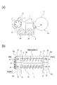
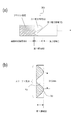
図4(a)は、現像スリーブ3の端部の構成を示す平面図である。現像スリーブ3の表面は、感光体ドラム11の画像形成領域と対向する画像形成幅領域A(印字可能幅領域)を有する。また、現像スリーブ3の表面は、現像スリーブ3の長手方向で、画像形成幅領域Aよりも外側に位置する第1領域Bと、現像スリーブ3の長手方向で、第1領域Bよりも外側に位置する第2領域Cと、を有する。なお、現像スリーブ3の長手方向は、感光体ドラム11の軸と平行な方向に相当する。
FIG. 4A is a plan view showing the configuration of the end portion of the developing
第1領域Bは、現像スリーブ3の周方向に、少なくとも第1粗さを有する第1粗さ領域X、及び、第1粗さよりも粗さが小さい第2粗さを有する第2粗さ領域Yを有する。第1粗さ領域Xは、矩形状に粗面化処理されたブラスト領域に相当し、第2粗さ領域Yは、表面処理がされていない非ブラスト領域に相当する。少なくとも第1粗さ領域Xは現像剤を担持可能である。なお、第1粗さ領域X及び第2粗さ領域Yの形状は、現像スリーブ3の端部を矩形状にマスキングし、ブラスト処理することで簡単に作ることができる。
The first region B includes, in the circumferential direction of the developing
ブレード19aの先端は、画像形成幅領域Aから第2領域Cまでに亘る現像スリーブ3の表面に(感光体ドラム11の軸と直交する方向で)対応する部位と対向する感光体ドラム11の表面の部位に対向して配置される。
The tip of the
ここで、第2粗さ領域Yは、表面処理されていないアルミニウム素管のままであり(Rz=3.0μm、Sm=100μm)、現像剤の搬送力が著しく低下しており、感光体ドラム11の対向開口部では現像スリーブ3上に現像剤コートは殆どされない状態となる。一方、第1粗さ領域Xでは画像形成幅領域Aと同じ表面処理がされているので、画像形成幅領域Aと同様の現像剤搬送性を有する。つまり、ここでは、現像スリーブ3の端部において感光体ドラム11と対向する位置で矩形状に現像剤コートの有無が繰り返される状態になる。
Here, the second roughness region Y is an aluminum base tube that has not been surface-treated (Rz = 3.0 μm, Sm = 100 μm), and the developer conveying force is significantly reduced, and the photosensitive drum In the
図4(b)は、現像スリーブ3の第1領域Bを示す展開図である。すなわち、図4(b)中には、現像スリーブ3の第1領域Bの1周分が示されている。第1粗さ領域Xの周方向長を10mm、第2粗さ領域Yの周方向長を約11mmとし、約21mm周期でこれらが繰り返されている。第2粗さ領域Yで現像剤コートが無い状態では、画像形成が不可能であるので画像形成幅領域Aより外側に第1領域Bを設けている。第1領域Bのさらに外側には第2領域Cが存在し、ここは表面処理されていない。
FIG. 4B is a development view showing the first region B of the developing
図5は、感光体ドラム11、及び、感光体ドラム11の周囲のパーツに関する長手位置関係を示す概念図である。図5では、各々のパーツの長手位置に関して、感光体ドラム11の軸の中心を通って軸と直交する平面から離れた位置が記載されている。ただし、数値に関しては、全幅を表示している。端部シールは、現像スリーブ3の第1領域Bのやや外側に位置している。端部シールは、磁気部材で出来ており、磁力線は現像スリーブ3の方向に伸びて、磁力線に沿って現像剤の磁気穂ができ、現像剤の端部からの漏れが防止される。
FIG. 5 is a conceptual diagram showing a longitudinal positional relationship regarding the
つまり、現像スリーブ3の第2領域Cでは現像剤コートされていない状態である。ブレード19aの端部は、現像剤容器2の外へ現像剤が漏れるのを防ぐために、現像剤コート幅より外側に設定され、現像スリーブ3の第2領域Cに対応する長手位置にある。
That is, the second area C of the developing
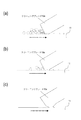
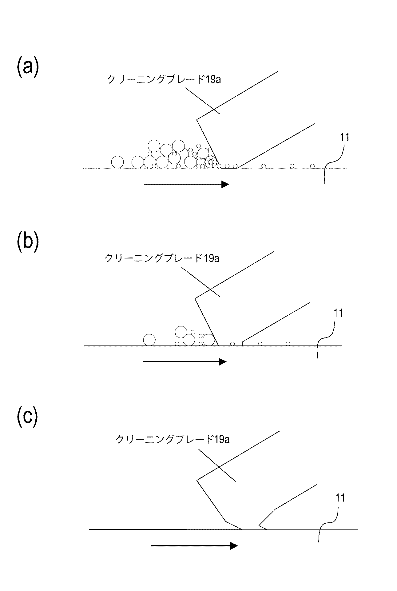
図6は、ブレード19aが感光体ドラム11の表面をクリーニングする様子を示す断面図である。図6では、ブレード19aが感光体ドラム11と当接して感光体ドラム11の回転中に受ける摩擦力を、現像スリーブ3の長手方向の領域毎に説明する。
FIG. 6 is a cross-sectional view showing how the
図6(a)は、画像形成幅領域Aに対応する感光体ドラム11の部位の様子を示す断面図である。図6(a)に示されるように、画像形成幅領域Aに対応する感光体ドラム11の領域では、ブレード19a及び感光体ドラム11のニップ部では、トナーや外添剤が供給されているので、これらが潤滑成分として働き、摩擦力が低減される。
FIG. 6A is a cross-sectional view illustrating a portion of the
図6(b)は、第1領域Bに対応する感光体ドラム11の部位の様子を示す断面図である。図6(b)に示されるように、現像スリーブ3の第1領域Bに対応する感光体ドラム11の領域は、画像形成幅領域Aの外側に相当するので、トナーは供給されないが、カブリトナーが供給される。そのために、潤滑成分は存在している。
FIG. 6B is a cross-sectional view showing the state of the portion of the
図6(c)は、第2領域Cに対応する感光体ドラム11の部位の様子を示す断面図である。図6(c)に示されるように、現像スリーブ3の第2領域Cに対応する感光体ドラム11の領域は、現像剤コートがされていない位置であるので、潤滑成分が殆ど供給されず、ゴムブレードと感光体ドラム11の表面との接触面積が増大し、摩擦力が大きくなる。
FIG. 6C is a cross-sectional view showing the state of the part of the
従来では、本発明でいう第1領域Bには画像形成幅領域Aと同じ表面処理がされ、第2領域Cの境界でクリーニングブレードが受ける摩擦係数の変動が大きくなっていた。そして、その摩擦係数の変動が大きくなった位置で、クリーニングブレードの歪みが発生し、クリーニングブレードの損傷、フィルミング、トナーすり抜け等のクリーニング性に関する問題が発生していたと考えられる。 Conventionally, the first region B referred to in the present invention is subjected to the same surface treatment as the image forming width region A, and the variation of the friction coefficient received by the cleaning blade at the boundary of the second region C has been large. Then, it is considered that the cleaning blade is distorted at a position where the fluctuation of the friction coefficient becomes large, and problems relating to cleaning properties such as damage to the cleaning blade, filming, and toner slipping have occurred.
これに対して、本実施例では、第1領域Bには第1粗さ領域X及び第2粗さ領域Yが形成されるので、感光体ドラム11の表面に供給されるカブリトナーの量が現像スリーブ3の周方向でのコート状態に応じて変化する。
On the other hand, in the present embodiment, the first roughness region X and the second roughness region Y are formed in the first region B, so that the amount of fog toner supplied to the surface of the
図7(a)は、第1領域Bの第1粗さ領域Xに対応する感光体ドラム11の部位の様子を示す断面図である。図7(a)に示されるように、第1粗さ領域Xに対応する部位では、ブレード19a及び感光体ドラム11の表面の間のニップ部では、潤滑剤の量が多い。したがって、このニップ部での摩擦力は小さい。
FIG. 7A is a cross-sectional view showing a portion of the
図7(b)は、第1領域Bの第2粗さ領域Yに対応する感光体ドラム11の部位の様子を示す断面図である。図7(b)に示されるように、第2粗さ領域Yに対応する部位では、ブレード19a及び感光体ドラム11の表面の間のニップ部では、潤滑剤の量が少ない。したがって、このニップ部での摩擦力は大きい。
FIG. 7B is a cross-sectional view illustrating a portion of the
前述した図7(a)及び図7(b)の説明からも分かるように、ブレード19a及び感光体ドラム11のニップ部での潤滑剤量の増減に応じて摩擦力(ブレードニップの巻き込み具合)が微細に変化する。その結果、ブレード19aの歪みを瞬間的に緩和することができ、ブレード19aが同じストレスを受け続けないようにすることができる。
As can be seen from the description of FIG. 7A and FIG. 7B described above, the frictional force (how the blade nip is entrapped) according to the increase / decrease in the amount of lubricant at the nip portion of the
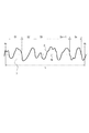
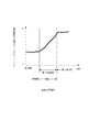
図8は、従来技術の構成において、長手方向で見たブレード19aが受ける平均摩擦力のイメージ図である(従来構成)。この従来の構成では、第1領域Bと第2領域Cの境界で、摩擦力の急激な変動がある。
FIG. 8 is an image diagram of the average frictional force that the
図9は、本実施例の構成において、長手方向で見たブレード19aが受ける平均摩擦力のイメージ図である(本実施例構成)。本実施例の構成では、第1領域Bでのカブリトナーの供給量が従来に比べ全体量として少なくなっており第2領域Cの摩擦力に近くなるため、摩擦力の急激な変動幅が従来に比べ抑えられる。
FIG. 9 is an image diagram of an average frictional force received by the
上記構成で、クリーニング性の評価試験を行った。評価条件は以下のとおりである。環境は、温度が23℃及び湿度が5%(常温低湿)、温度が30℃及び湿度が80%(高温多湿)である。通紙条件は、A4横、2枚間欠モード(2枚連続通紙後休止期間を設ける)、10万枚耐久である。プリント画像は、印字率が5%で横帯である。帯電ローラ印加バイアスは、AC+DC、ACによる放電条件は強めにし、感光体表面の放電劣化がやや促進される条件で行った。 With the above configuration, a cleaning property evaluation test was performed. The evaluation conditions are as follows. The environment has a temperature of 23 ° C. and a humidity of 5% (normal temperature and low humidity), a temperature of 30 ° C. and a humidity of 80% (high temperature and high humidity). The sheet passing condition is A4 horizontal, two-sheet intermittent mode (a pause period is provided after two sheets are continuously passed), and 100,000 sheets are durable. The print image is a horizontal band with a printing rate of 5%. The charging roller application bias was performed under conditions where AC + DC and AC discharge conditions were strengthened and discharge deterioration on the surface of the photoreceptor was somewhat accelerated.
図10(a)は、ブレード19aのエッジが抉れた様子を示す拡大断面図である。また、図10(b)は、ブレード19aのエッジが落ちた様子を示す拡大断面図である。前述のクリーニング性の評価試験にあたっては、評価項目としては、クリーニングに関する所で、ブレード欠け、フィルミング、トナーすり抜けを評価した。ただし、ブレード欠けの評価は、5万枚耐久終了後のブレード19aのエッジ抉れ(図10(a)参照)、エッジ落ち(図10(b)参照)のレベルを評価した。
FIG. 10A is an enlarged cross-sectional view showing a state in which the edge of the
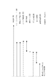
画像形成幅領域Aの長手方向に5点測定した時の平均値と端部(第1領域Bと第2領域Cの境界付近)での測定値を[表1]に示す。また、フィルミング/トナーすり抜け発生の有無も合わせて[表1]に示す。 [Table 1] shows the average values and the measured values at the edges (near the boundary between the first region B and the second region C) when five points are measured in the longitudinal direction of the image forming width region A. Table 1 also shows whether filming / toner slipping has occurred.
○:発生なし
△:感光体表面に僅かに付着物が見られるが、画像上問題無し
×:画像に出る(端部の場合は付着領域が広がり画像域まで進出する)。
トナーすり抜け
○:発生無し
△:帯電ローラが僅かに汚れ、トナーすり抜けがみられるが、画像上問題無し
×:画像に出る(帯電ローラ表面にトナーが付着し、帯電不良として画像に出る。トナーすり抜けが直接画像に出る)。
Toner slipping ○: No occurrence Δ: The charging roller is slightly soiled and toner slipping is observed, but there is no problem on the image ×: Appears on the image (Toner adheres to the surface of the charging roller and appears on the image as charging failure. Toner slipping out) Appears directly in the image).
高温多湿環境では感光体ドラム11の表面とブレード19aの密着性が増し、通常摩擦力が増加する傾向となり、ブレード19aのビビリ、捲れが厳しくなる。ここでは、端部の損傷が画像形成幅領域Aに比べやや大きくなったが、ビビリ等から誘発されるトナーすり抜けやフィルミングは画像上発生しなかった。一方、低湿環境ではトナーや外添剤の帯電量が増し感光体ドラム11の表面との付着性が増すので、トナーすり抜けや、外添剤フィルミングが厳しくなるが、これに関しても画像上発生しなかった。
In a high-temperature and high-humidity environment, the adhesion between the surface of the
ここでは、現像スリーブ3の第1領域Bで周方向の表面粗さを変化させることで現像剤コート状態を変え、感光体ドラム11の表面へのトナー供給量を周期的に異ならせている。これにより、ブレード19aのニップで潤滑成分として働くトナーの存在状態を変化させ、ブレード19aの歪みを緩和させている。
Here, the developer coating state is changed by changing the circumferential surface roughness in the first region B of the developing
ここでは、第1粗さ領域Xの10mmと第2粗さ領域Yの11mmを繰り返すことで上記の結果が得られたが、この周期を短くしすぎると感光体ドラム11の表面に供給されるトナーの周方向での分布が均一に近づくので期待する効果が得られなくなる。
Here, the above result was obtained by repeating 10 mm of the first roughness region X and 11 mm of the second roughness region Y. However, if this period is too short, the surface is supplied to the surface of the
第1粗さ領域X及び第2粗さ領域Yの周期は、感光体ドラム11の表面と現像スリーブ3の表面の周速比等を考慮して決めればよい。つまり、感光体ドラム11の表面へのトナー供給量分布を効果的なものにするには、周速比が大きい(感光体ドラム11に対して現像スリーブ3の周速が大きい方向)場合は周期も長く設定するべきである。
The period of the first roughness region X and the second roughness region Y may be determined in consideration of the peripheral speed ratio between the surface of the
実施例1では、現像方式として2成分現像方式を用いたが、本発明はこれに限定されるものではない。すなわち、磁性トナーの1成分現像、非磁性トナーの1成分現像であっても感光体ドラム11の表面へのトナーの供給され方が、本発明の意図するものであればなんら問題なく適用できる。
In Example 1, the two-component development method was used as the development method, but the present invention is not limited to this. That is, even in the case of one-component development of magnetic toner and one-component development of non-magnetic toner, any method can be applied without any problem as long as the method of supplying toner to the surface of the
図11は、従来型の現像スリーブ503の端部の構成を示す平面図である。図11に示されるように、ここでは第1領域B5として周方向の変化を持たせず、画像形成幅領域Aと同じ状態としている(所謂従来型)。その他の構成は実施例1と同じとした。評価結果を[表1]に示す。
FIG. 11 is a plan view showing a configuration of an end portion of a conventional developing
ブレード19aの端部の損傷が実施例1に比べ大きいものとなっていた。これは、第1領域B5と第2領域Cの境界においてブレード19aが受ける摩擦力の変化が大きくブレードが大きく歪んだためと考えられる。これに起因して、ブレード19aの端部において、トナーすり抜けやフィルミングも発生していた。画像形成幅領域Aでのブレード19aの損傷が、実施例1に比べて悪くなっているのは、ブレード19aの端部の挙動が不安定になるため、その影響が長手全域に及んでいるのではないかと考えられる。
The damage at the end of the
図12(a)は、ローレット加工型の現像スリーブ603の端部の構成を示す平面図であり、図12(b)は、図12(a)の断面図である。図12(a)及び図12(b)に示されるように、ここでは現像スリーブ603の表面にローレット加工したものを用いた。ローレット加工は、現像剤の搬送性を向上するのに周方向に深い溝を切る手法を用いている。溝の深さを0.2mm、溝間隔を1.5mmとした。現像スリーブ603以外の構成は実施例1と同じとした。評価結果を[表1]に示す。
FIG. 12A is a plan view showing the configuration of the end of the
ブレード19aの端部の損傷が実施例1に比べ大きいものとなっていた。これは第1領域B6と第2領域Cの境界においてブレード19aが受ける摩擦力の変化が大きくブレードが大きく歪んだためと考えられる。これはローレット加工では、周方向での感光体ドラム11の表面へのトナーの供給量が十分に変わっていないためだと考えられる。
The damage at the end of the
図13(a)は、実施例2に係る画像形成装置が備える現像スリーブ203の構成を示す平面図である。図13(b)は、第1領域B2における現像スリーブ203の展開図である。実施例2の現像スリーブ203の構成のうち実施例1の現像スリーブ3と同一の構成及び効果に関しては、同一の符号を用いて説明を適宜省略する。実施例2においても、実施例1と同様の画像形成装置に適用することができるため、画像形成装置の説明は省略する。実施例2の現像スリーブ203が実施例1の現像スリーブ3と異なる点は、以下の点である。
FIG. 13A is a plan view illustrating a configuration of the developing
第1粗さ領域X2が現像スリーブ203の表面上で周方向で占める割合は、現像スリーブ203の端部から中央部に向かって連続的に増加する。同時に、第2粗さ領域Y2が現像スリーブ203の表面上で周方向で占める割合は、現像スリーブ203の端部から中央部に向かって連続的に減少する。ここでは、側面視で、第1粗さ領域X2が現像スリーブ203の端部から中央部に向かって直線的に増加し、第2粗さ領域Y2が現像スリーブ203の端部から中央部に向かって直線的に減少している。
The ratio of the first roughness region X2 in the circumferential direction on the surface of the developing
図13(b)に示されるように、ここでは現像スリーブ203の1周分(約63mm)を1周期(第1粗さ領域X+第2粗さ領域Y)とした。また、第1粗さ領域X2が占める割合を軸方向で端部から中央部に行くにつれ連続的に大きくなるようにした。必然的に第2粗さ領域Y2が占める割合は小さくなる。その他の構成は実施例1と同じとした。評価結果を[表1]に示す。
As shown in FIG. 13B, here, one cycle (about 63 mm) of the developing
フィルミング、トナーすり抜けは発生しなかった。また、ブレード19aの損傷が実施例1と比べて良くなっていた。この理由については以下の様に考えられる。実施例2では、実施例1と同様に、第1粗さ領域X2と第2粗さ領域Y2の周期を十分にとることで周方向のトナー供給量を効果的に変えているのに加え、長手方向の供給量を連続的に変化させている。これは、第1粗さ領域X2の割合を連続的に変えることで、現像スリーブ303の端部から中央部に向かって現像剤コート面積を連続的に増加させることで達成している。
No filming or toner slip occurred. Further, the damage of the
図14は、ブレード19aが受ける摩擦力の長手方向の分布変化をイメージしたグラフである。トナー(潤滑成分)の供給量が軸方向で中央部に向かって連続的に増加することから、摩擦力変化はこのようになると考えられる。第1領域B2と第2領域Cの境界、第1領域B2と画像形成幅領域Aの境界部においても摩擦力が急激に変化する部分がなくなるので、ブレード19aの歪みは実施例1に比べさらに良いものとなると考えられる。実施例1では、端部や画像形成幅領域Aの一部にフィルミングやトナーすり抜けが見られたが、実施例2では発生していなかったことからも、さらに安定したクリーニングが出来ていると考えられる。
FIG. 14 is a graph depicting the distribution change in the longitudinal direction of the frictional force received by the
図15(a)は、実施例3に係る画像形成装置が備える現像スリーブ303の構成を示す平面図である。図15(b)は、第1領域B3における現像スリーブ303の展開図である。実施例3の現像スリーブ303の構成のうち実施例1の現像スリーブ3と同一の構成及び効果に関しては、同一の符号を用いて説明を適宜省略する。実施例3においても、実施例1と同様の画像形成装置に適用することができるため、画像形成装置の説明は省略する。実施例3の現像スリーブ303が実施例1及び2の現像スリーブ3、203と異なる点は、以下の点である。
FIG. 15A is a plan view illustrating a configuration of the developing
第1粗さ領域X3が現像スリーブ303の表面上で軸方向で占める割合は、現像スリーブ303の端部から中央部に向かって連続的に増加する。同時に、第2粗さ領域Y3が現像スリーブ303の表面上で軸方向で占める割合は、現像スリーブ303の端部から中央部に向かって連続的に減少する。ここでは、側面視で、第1粗さ領域X3が現像スリーブ303の端部から中央部に向かって曲線的に増加し、第2粗さ領域Y3が現像スリーブ303の端部から中央部に向かって曲線的に減少している。
The ratio of the first roughness region X3 in the axial direction on the surface of the developing
図15(a)に示されるように、現像スリーブ303は、周方向に向かって蛇行した曲線状に境界線が形成されている。
As shown in FIG. 15A, the developing
また、図15(b)に示されるように、ここでは周期を31.5mmとした。また第1粗さ領域X3が占める割合を端部から中央部よりに行くにつれ連続的に大きくなるようにした。その他の構成は実施例1と同じとした。評価結果を[表1]に示す。 Further, as shown in FIG. 15B, the cycle is 31.5 mm here. Further, the ratio of the first roughness region X3 is continuously increased from the end portion to the center portion. Other configurations are the same as those in the first embodiment. The evaluation results are shown in [Table 1].
実施例1〜3の構成によれば、コストアップを招来せずに、感光体ドラム11の表面をクリーニングするブレード19aが有するクリーニング性能の耐久性が向上する。なお、従来では、ブレード19aを備える画像形成装置100では、ブレード19aの端部でのビビリ、捲れ、フィルミングといった問題が発生しやすい状況にあった。本発明では、ブレード19aの端部の付近で発生するクリーニング性に関わる問題を、装置が複雑化(コストアップ、大型化)しない構成で、かつ、弊害も発生させないで解消することができる。
According to the configurations of the first to third embodiments, the durability of the cleaning performance of the
11 感光体ドラム11(像担持体)
3 現像スリーブ3(現像剤担持体)
19a ブレード(クリーニングブレード)
A 画像形成幅領域
B、B2、B3・・・第1領域
X、X2、X3・・・・第1粗さ領域
Y、Y2、Y3・・・・第2粗さ領域
C 第2領域
100 画像形成装置
11 Photosensitive drum 11 (image carrier)
3 Development sleeve 3 (developer carrier)
19a Blade (cleaning blade)
A Image formation width region B, B2, B3... First region X, X2, X3... First roughness region Y, Y2, Y3... Second roughness region
Claims (2)
前記像担持体の軸と平行な方向に延び、前記像担持体の表面の静電像を現像剤で現像する現像剤担持体と、
前記像担持体の軸と平行な方向に延び、前記像担持体と接触して前記像担持体の表面に担持される現像剤を除去するクリーニングブレードと、を備え、
前記現像剤担持体の表面は、
前記現像剤担持体の長手方向で、前記像担持体の画像形成領域と対向する画像形成幅領域よりも外側に位置する第1領域と、
前記現像剤担持体の長手方向で、前記第1領域よりも外側に位置する第2領域と、を有し、
前記第1領域は、
前記現像剤担持体の周方向で、少なくとも第1粗さを有する第1粗さ領域と、
前記第1粗さよりも粗さが小さい第2粗さを有する第2粗さ領域と、を有し、少なくとも前記第1粗さ領域は現像剤を担持可能であり、
前記クリーニングブレードの先端は、前記画像形成幅領域から前記第2領域までに亘る前記現像剤担持体の表面に対応する前記像担持体の表面の部位に対向して配置されることを特徴とする画像形成装置。 An image carrier;
A developer carrier that extends in a direction parallel to the axis of the image carrier and develops an electrostatic image on the surface of the image carrier with a developer;
A cleaning blade that extends in a direction parallel to the axis of the image carrier and removes the developer carried on the surface of the image carrier in contact with the image carrier;
The surface of the developer carrier is
A first region located outside the image forming width region facing the image forming region of the image carrier in the longitudinal direction of the developer carrier;
A second region located outside the first region in the longitudinal direction of the developer carrier,
The first region is
A first roughness region having at least a first roughness in a circumferential direction of the developer carrier;
A second roughness region having a second roughness smaller than the first roughness, and at least the first roughness region can carry a developer,
A tip of the cleaning blade is disposed to face a portion of the surface of the image carrier corresponding to the surface of the developer carrier from the image forming width region to the second region. Image forming apparatus.
前記第2粗さ領域が前記現像剤担持体の表面上で周方向で占める割合は、前記現像剤担持体の前記端部から前記中央部に向かって連続的に減少することを特徴とする請求項1に記載の画像形成装置。 The proportion of the first roughness region in the circumferential direction on the surface of the developer carrier increases continuously from the end of the developer carrier toward the center,
The ratio of the second roughness region in the circumferential direction on the surface of the developer carrying member continuously decreases from the end of the developer carrying member toward the central portion. Item 2. The image forming apparatus according to Item 1.
Priority Applications (1)
| Application Number | Priority Date | Filing Date | Title |
|---|---|---|---|
| JP2010257055A JP5615139B2 (en) | 2010-11-17 | 2010-11-17 | Image forming apparatus |
Applications Claiming Priority (1)
| Application Number | Priority Date | Filing Date | Title |
|---|---|---|---|
| JP2010257055A JP5615139B2 (en) | 2010-11-17 | 2010-11-17 | Image forming apparatus |
Publications (2)
| Publication Number | Publication Date |
|---|---|
| JP2012108317A true JP2012108317A (en) | 2012-06-07 |
| JP5615139B2 JP5615139B2 (en) | 2014-10-29 |
Family
ID=46493997
Family Applications (1)
| Application Number | Title | Priority Date | Filing Date |
|---|---|---|---|
| JP2010257055A Expired - Fee Related JP5615139B2 (en) | 2010-11-17 | 2010-11-17 | Image forming apparatus |
Country Status (1)
| Country | Link |
|---|---|
| JP (1) | JP5615139B2 (en) |
Cited By (1)
| Publication number | Priority date | Publication date | Assignee | Title |
|---|---|---|---|---|
| JP2023089852A (en) * | 2021-12-16 | 2023-06-28 | キヤノン株式会社 | image forming device |
Citations (6)
| Publication number | Priority date | Publication date | Assignee | Title |
|---|---|---|---|---|
| JP2006106260A (en) * | 2004-10-04 | 2006-04-20 | Seiko Epson Corp | Image forming apparatus |
| JP2007121951A (en) * | 2005-10-31 | 2007-05-17 | Seiko Epson Corp | Developing device, image forming apparatus, and image forming system |
| US20070112484A1 (en) * | 2005-11-15 | 2007-05-17 | Se-Yong Lee | Method of determination of driving mode of hybrid vehicle |
| US20080310889A1 (en) * | 2007-06-12 | 2008-12-18 | Konica Minolta Business Technologies, Inc. | Developing roller specific for mono-component developing apparatus |
| JP2008310252A (en) * | 2007-06-18 | 2008-12-25 | Konica Minolta Business Technologies Inc | One-component developing device and developing roller for use in the developing device |
| JP2009042581A (en) * | 2007-08-10 | 2009-02-26 | Canon Inc | Image forming apparatus and process cartridge |
-
2010
- 2010-11-17 JP JP2010257055A patent/JP5615139B2/en not_active Expired - Fee Related
Patent Citations (8)
| Publication number | Priority date | Publication date | Assignee | Title |
|---|---|---|---|---|
| JP2006106260A (en) * | 2004-10-04 | 2006-04-20 | Seiko Epson Corp | Image forming apparatus |
| JP2007121951A (en) * | 2005-10-31 | 2007-05-17 | Seiko Epson Corp | Developing device, image forming apparatus, and image forming system |
| US20070112484A1 (en) * | 2005-11-15 | 2007-05-17 | Se-Yong Lee | Method of determination of driving mode of hybrid vehicle |
| US20080310889A1 (en) * | 2007-06-12 | 2008-12-18 | Konica Minolta Business Technologies, Inc. | Developing roller specific for mono-component developing apparatus |
| JP2008309854A (en) * | 2007-06-12 | 2008-12-25 | Konica Minolta Business Technologies Inc | One-component developing device and developing roller for use in the developing device |
| JP2008310252A (en) * | 2007-06-18 | 2008-12-25 | Konica Minolta Business Technologies Inc | One-component developing device and developing roller for use in the developing device |
| JP2009042581A (en) * | 2007-08-10 | 2009-02-26 | Canon Inc | Image forming apparatus and process cartridge |
| US20090252529A1 (en) * | 2007-08-10 | 2009-10-08 | Canon Kabushiki Kaisha | Process cartridge and image forming apparatus |
Cited By (2)
| Publication number | Priority date | Publication date | Assignee | Title |
|---|---|---|---|---|
| JP2023089852A (en) * | 2021-12-16 | 2023-06-28 | キヤノン株式会社 | image forming device |
| JP7802516B2 (en) | 2021-12-16 | 2026-01-20 | キヤノン株式会社 | Image forming device |
Also Published As
| Publication number | Publication date |
|---|---|
| JP5615139B2 (en) | 2014-10-29 |
Similar Documents
| Publication | Publication Date | Title |
|---|---|---|
| US10551763B2 (en) | Image forming apparatus and cartridge having a charging roller with a surface layer including projections | |
| JP5253487B2 (en) | Image forming apparatus | |
| JP2010281907A (en) | Transfer device and image forming apparatus | |
| EP2515179A2 (en) | Image forming apparatus | |
| JP2012163601A (en) | Image forming apparatus | |
| US7917069B2 (en) | Development apparatus including a first developer member made of pure aluminum or an aluminum alloy and a second developer member of stainless steel | |
| JP4963208B2 (en) | Image forming unit, process cartridge, and image forming apparatus | |
| JP2010014984A (en) | Image forming apparatus | |
| CN105005188A (en) | Developing roller and developing apparatus and image forming apparatus using the same | |
| JP2012042608A (en) | Developer regulating member, developing apparatus, process unit, and image forming apparatus | |
| JP5615139B2 (en) | Image forming apparatus | |
| JP2007011084A (en) | Image forming method and image forming apparatus | |
| JP2019003057A (en) | Image forming apparatus and cartridge | |
| JP5359766B2 (en) | Image forming apparatus | |
| JP4936539B2 (en) | Image forming apparatus | |
| JP4261941B2 (en) | Image forming method, developing device, process cartridge, and image forming apparatus | |
| JP2023130007A (en) | Developing device and image forming device equipped with the same | |
| JP2022059718A (en) | A developing device and an image forming device equipped with the developing device. | |
| JP2008003110A (en) | Charging device, process cartridge, and image forming apparatus | |
| JP5575003B2 (en) | Developing roller, developing device, and image forming apparatus | |
| JP2015028517A (en) | Developing unit, image forming unit, and image forming apparatus | |
| JP4736575B2 (en) | Developing roller | |
| JP4261940B2 (en) | Image forming method, developing device, process cartridge, and image forming apparatus | |
| JP2008009149A (en) | Image forming apparatus | |
| JP2011081039A (en) | Image forming apparatus |
Legal Events
| Date | Code | Title | Description |
|---|---|---|---|
| A621 | Written request for application examination |
Free format text: JAPANESE INTERMEDIATE CODE: A621 Effective date: 20131025 |
|
| A977 | Report on retrieval |
Free format text: JAPANESE INTERMEDIATE CODE: A971007 Effective date: 20140516 |
|
| A131 | Notification of reasons for refusal |
Free format text: JAPANESE INTERMEDIATE CODE: A131 Effective date: 20140520 |
|
| A521 | Request for written amendment filed |
Free format text: JAPANESE INTERMEDIATE CODE: A523 Effective date: 20140718 |
|
| TRDD | Decision of grant or rejection written | ||
| A01 | Written decision to grant a patent or to grant a registration (utility model) |
Free format text: JAPANESE INTERMEDIATE CODE: A01 Effective date: 20140812 |
|
| A61 | First payment of annual fees (during grant procedure) |
Free format text: JAPANESE INTERMEDIATE CODE: A61 Effective date: 20140909 |
|
| R151 | Written notification of patent or utility model registration |
Ref document number: 5615139 Country of ref document: JP Free format text: JAPANESE INTERMEDIATE CODE: R151 |
|
| LAPS | Cancellation because of no payment of annual fees |