JP2012108263A - Image calculation unit and image calculation program - Google Patents
Image calculation unit and image calculation program Download PDFInfo
- Publication number
- JP2012108263A JP2012108263A JP2010256193A JP2010256193A JP2012108263A JP 2012108263 A JP2012108263 A JP 2012108263A JP 2010256193 A JP2010256193 A JP 2010256193A JP 2010256193 A JP2010256193 A JP 2010256193A JP 2012108263 A JP2012108263 A JP 2012108263A
- Authority
- JP
- Japan
- Prior art keywords
- image
- distance
- distance information
- parallax
- unit
- Prior art date
- Legal status (The legal status is an assumption and is not a legal conclusion. Google has not performed a legal analysis and makes no representation as to the accuracy of the status listed.)
- Withdrawn
Links
Images


Landscapes
- Automatic Focus Adjustment (AREA)
- Studio Devices (AREA)
- Focusing (AREA)
Abstract
Description
本発明は、画像演算装置および画像演算プログラムに関する。 The present invention relates to an image calculation device and an image calculation program.
レンズ光学系の絞り位置にRGB三色のカラーフィルタからなる構造化開口を配置したカメラでシーンを撮影することにより、一枚の画像データからシーンの奥行き情報を取得する技術が知られている(例えば非特許文献1)。
[先行技術文献]
[非特許文献1]カメラの絞りに色フィルタを用いた奥行き推定と前景マット抽出(Visual Computing/グラフィクスとCAD合同シンポジウム2008)
A technique is known in which scene depth information is obtained from a single piece of image data by photographing a scene with a camera in which a structured aperture composed of RGB color filters is arranged at the aperture position of the lens optical system ( For example, Non-Patent Document 1).
[Prior art documents]
[Non-Patent Document 1] Depth estimation and foreground mat extraction using a color filter for the diaphragm of a camera (Visual Computing / Graphics and CAD Joint Symposium 2008)
奥行き情報を演算する過程で用いられるマッチング処理の局所ウィンドウについて、そのサイズを適切に設定しないと正確な奥行き情報が得られなかった。 For the local window of the matching process used in the process of calculating the depth information, accurate depth information cannot be obtained unless the size is set appropriately.
上記課題を解決するために、本発明の第1の態様における画像演算装置は、入射する被写体光束を複数の波長帯に分離して検出する受光素子から出力され、複数の波長帯の少なくとも2つに対応する画像が互いに視差を有する視差画像データを取得する画像取得部と、視差画像データにおいて合焦状態にある少なくとも一つの合焦物体までの距離情報と非合焦状態にある少なくとも一つの非合焦物体までの距離情報を取得する距離情報取得部と、距離情報に基づくウィンドウサイズにより規定される局所ウィンドウを用いて視差画像データ間のマッチング処理を行うことにより、視差画像に含まれる複数の物体に対して奥行き方向に分離して輪郭を定める演算部とを備える。 In order to solve the above-described problem, the image calculation apparatus according to the first aspect of the present invention outputs from a light receiving element that detects an incident subject light beam by separating it into a plurality of wavelength bands, and outputs at least two of the plurality of wavelength bands. An image acquisition unit that acquires parallax image data in which images corresponding to each other have parallax, and distance information to at least one focused object that is in focus in the parallax image data and at least one non-focused state By performing a matching process between parallax image data using a distance information acquisition unit that acquires distance information to a focused object and a local window defined by a window size based on the distance information, a plurality of parallax images are included. A computing unit that separates the object in the depth direction and determines an outline.
上記課題を解決するために、本発明の第2の態様における画像演算プログラムは、入射する被写体光束を複数の波長帯に分離して検出する受光素子から出力され、複数の波長帯の少なくとも2つに対応する画像が互いに視差を有する視差画像データを取得する画像取得ステップと、視差画像データにおいて合焦状態にある少なくとも一つの合焦物体までの距離情報と非合焦状態にある少なくとも一つの非合焦物体までの距離情報を取得する距離情報取得ステップと、距離情報に基づくウィンドウサイズにより規定される局所ウィンドウを用いて視差画像データ間のマッチング処理を行うことにより、視差画像に含まれる複数の物体に対して奥行き方向に分離して輪郭を定める演算ステップとをコンピュータに実行させる。 In order to solve the above-described problem, an image calculation program according to the second aspect of the present invention is output from a light receiving element that detects an incident subject luminous flux by separating it into a plurality of wavelength bands, and at least two of the plurality of wavelength bands are detected. An image acquisition step of acquiring parallax image data in which images corresponding to each other have parallax, distance information to at least one in-focus object in the in-focus state in the parallax image data, and at least one non-in-focus state A distance information acquisition step for acquiring distance information to the in-focus object and a matching process between the parallax image data using a local window defined by the window size based on the distance information, thereby performing a plurality of processes included in the parallax image And causing the computer to execute a calculation step of determining an outline by separating the object in the depth direction.
なお、上記の発明の概要は、本発明の必要な特徴の全てを列挙したものではない。また、これらの特徴群のサブコンビネーションもまた、発明となりうる。 It should be noted that the above summary of the invention does not enumerate all the necessary features of the present invention. In addition, a sub-combination of these feature groups can also be an invention.
以下、発明の実施の形態を通じて本発明を説明するが、以下の実施形態は特許請求の範囲にかかる発明を限定するものではない。また、実施形態の中で説明されている特徴の組み合わせの全てが発明の解決手段に必須であるとは限らない。 Hereinafter, the present invention will be described through embodiments of the invention, but the following embodiments do not limit the invention according to the claims. In addition, not all the combinations of features described in the embodiments are essential for the solving means of the invention.
まず、本実施形態におけるシーンの奥行き情報の取得原理について説明する。ここで、シーンの奥行き情報とは、シーンを構成する被写体としての各オブジェクト間の相対的な前後関係を示す距離情報である。画像演算装置は、距離情報として例えば、シーンの奥行き方向における合焦面を基準として、当該基準からそれぞれのオブジェクトの距離を出力する。画像演算装置は、特に、シーンを構成する各オブジェクトに対して、算出された距離に基づいて奥行き方向に分離して輪郭を定める。 First, the principle of acquiring scene depth information in this embodiment will be described. Here, the depth information of the scene is distance information indicating a relative front-rear relationship between each object as a subject constituting the scene. For example, the image calculation device outputs the distance of each object from the reference with respect to the focal plane in the depth direction of the scene as the reference. In particular, the image calculation device separates the objects in the scene in the depth direction based on the calculated distance and defines the contour.
本実施形態においては、被写体光束をCCD、CMOS等によって構成される受光素子に導く光学系に、構造化開口を挿入して、奥行き情報を演算するための補助撮影画像を取得する。構造化開口は、光学系に挿入されたときに、R(赤)G(緑)B(青)の各カラーフィルタが、光学系の光軸に対してそれぞれ偏心した位置となるように設けられて構成されている。例えば、光軸中心から、左方向へ放射状に延在するGフィルタ領域、上方向へ放射状に延在するRフィルタ領域および右方向へ放射状に延在するBフィルタ領域のようにカラーフィルタパターンが形成される。また、受光素子は、RGBのいずれかのカラーフィルタが各画素上に配置されており、例えば4画素を1組とするベイヤー配列が採用される。本実施形態に係る構造化開口の構成、および受光素子の構成は、後に詳述する。 In the present embodiment, a structured aperture is inserted into an optical system that guides a subject light beam to a light receiving element constituted by a CCD, a CMOS, etc., and an auxiliary captured image for calculating depth information is acquired. The structured aperture is provided so that each color filter of R (red), G (green), and B (blue) is decentered with respect to the optical axis of the optical system when inserted into the optical system. Configured. For example, a color filter pattern is formed such as a G filter region extending radially from the optical axis center to the left, an R filter region extending radially upward, and a B filter region extending radially to the right. Is done. The light receiving element has one of RGB color filters arranged on each pixel. For example, a Bayer arrangement in which four pixels are one set is employed. The structure of the structured opening and the structure of the light receiving element according to this embodiment will be described in detail later.
上述の例によるカラーフィルタパターンが形成された構造化開口を通過した被写体光束を、上述の受光素子で撮影した場合、焦点の合った奥行きより近い点はRが下、Gが右、Bが左方向にそれぞれずれて観測される。焦点の合った奥行きより遠い点ではずれ方向が逆になる。焦点の合っている奥行きでは画像はずれない。つまり、焦点の合っていない奥行きでは、シーンの同じ点が色ごとにずれて観察される。 When the subject light flux that has passed through the structured aperture in which the color filter pattern according to the above example is formed is photographed by the above-described light receiving element, R is below, G is on the right, and B is on the left near the in-focus depth. Observed in different directions. The direction of displacement is reversed at points farther than the in-focus depth. The image will not shift at the depth of focus. In other words, at the out-of-focus depth, the same point in the scene is observed shifted for each color.
別言すれば、撮影した補助撮影画像のRGB成分であるIr、Ig、Ibは、三視点のステレオ画像となる。仮想的な中央の視点をリファレンス座標に取れば、リファレンス座標(x,y)における視差をd画素とすると、Ir(x,y−d)、Ig(x+d,y)、Ib(x−d,y)が対応するから、これらが最も良く一致するdを視差の推定値とすることができる。しかし、観測波長帯が異なるため対応点の輝度レベルは位置しないので、単純な輝度の差分をマッチング指標にすることはできない。 In other words, I r , I g , and I b that are RGB components of the captured auxiliary captured image are three-viewpoint stereo images. If the virtual central viewpoint is taken as the reference coordinate, and the parallax at the reference coordinate (x, y) is d pixels, I r (x, y−d), I g (x + d, y), I b (x -D, y) corresponds, and d that best matches them can be used as an estimated value of parallax. However, since the luminance level of the corresponding point is not located because the observation wavelength bands are different, a simple luminance difference cannot be used as a matching index.
そこで、ここでは自然画像の色成分は局所的に線形関係を示す傾向が高いことを利用する。(x,y)の周りに局所ウィンドウw(x,y)を考え、そこに含まれる画素色の集合をS(x,y;d)={(Ir(s,t−d)、Ig(s+d,t)、Ib(s−d,t))|(s,t)∈w(x,y)}とすると、真のdのときに分布が最も直線に近くなると考えられる。 Therefore, the fact that the color component of the natural image has a high tendency to show a linear relationship locally is used here. A local window w (x, y) is considered around (x, y), and a set of pixel colors included therein is defined as S (x, y; d) = {(I r (s, t−d), I If g (s + d, t), I b (s−d, t)) | (s, t) ∈w (x, y)}, the distribution is considered to be closest to a straight line when true d.
ここではRGB間の線形関係を計る指標として以下を用いる。
![]()
![]()
行列の性質からλ0+λ1+λ2=σr 2+σg 2+σb 2 (=trace(Σ))であるので、固有値間の大小に差があるほど式(1)は小さくなる。直線的な分布(λ0>>λ1、λ2)であればLは0に近く、完全無相関(固有値がR、G、B軸に沿った分散に等しい)のとき最大値L=1をとる。 Since it is λ 0 + λ 1 + λ 2 = σ r 2 + σ g 2 + σ b 2 (= trace (Σ)) due to the nature of the matrix, equation (1) becomes smaller as there is a difference in magnitude between eigenvalues. If the distribution is linear (λ 0 >> λ 1 , λ 2 ), L is close to 0, and the maximum value L = 1 when the correlation is completely uncorrelated (the eigenvalue is equal to the variance along the R, G, and B axes). Take.
画像の各点、おおび取りうる範囲の各視差dについてL(x,y;d)を計算する必要があるが、Summed Area Tableを用いてIr、Ig、Ibとそれらの二乗と積の表を計算しておけば、局所ウィンドウのサイズに依存せずに共分散行列Σの各要素を計算することができる。また、式(1)の分子は行列の性質からλ0λ1λ2=det(Σ)であるので固有値を実際に計算する必要はない。 It is necessary to calculate L (x, y; d) for each point of the image, and for each disparity d in the range that can be taken, but using Summed Area Table, I r , I g , I b and their squares If the product table is calculated, each element of the covariance matrix Σ can be calculated without depending on the size of the local window. Further, since the numerator of the equation (1) is λ 0 λ 1 λ 2 = det (Σ) due to the matrix property, it is not necessary to actually calculate the eigenvalue.
上述のように計算される各オブジェクト単位の視差dにより、シーンの奥行き情報を推定することができる。本実施形態に係る画像演算装置としての一眼レフカメラは、このようなシーンの奥行き情報の取得原理を採用する。ただし、上述の手法において、マッチング処理を行う局所ウィンドウのウィンドウサイズを適切に設定しなければ、算出される距離、および算出距離から確定されるオブジェクトの輪郭の精度が低くなる。そこで、本実施形態の一眼レフカメラでは、奥行き情報の算出において、予め取得されている距離情報を利用してウィンドウサイズの最適化を図る。以下に本実施形態について説明する。 The depth information of the scene can be estimated by the parallax d of each object calculated as described above. The single-lens reflex camera as the image arithmetic apparatus according to the present embodiment employs such a principle of acquiring depth information of a scene. However, in the above-described method, if the window size of the local window for performing the matching process is not set appropriately, the calculated distance and the accuracy of the contour of the object determined from the calculated distance are lowered. In view of this, in the single-lens reflex camera of this embodiment, the optimization of the window size is attempted using the distance information acquired in advance in the calculation of the depth information. This embodiment will be described below.
図1は、本実施形態に係る一眼レフカメラ200の要部断面図である。一眼レフカメラ200は、撮影レンズであるレンズユニット210とカメラボディであるカメラユニット230が組み合わされて撮像装置として機能する。
FIG. 1 is a cross-sectional view of a main part of a single-
レンズユニット210は、光軸201に沿って配列されたレンズ群211を備える。レンズ群211には、フォーカスレンズ212、ズームレンズ213が含まれる。また、光軸201に沿って、絞り214および構造化開口ユニット300も配列される。構造化開口ユニット300は、被写体光束に対して挿抜することができる。
The
レンズユニット210は、フォーカスレンズ212、絞り214の駆動などレンズユニット210の制御および演算を司るレンズシステム制御部216を備える。レンズユニット210を構成する各要素は、レンズ鏡筒217に支持されている。位置センサ221は、フォーカスレンズ212の位置を検出して、レンズシステム制御部216へ出力する。
The
また、レンズユニット210は、カメラユニット230との接続部にレンズマウント218を備え、カメラユニット230が備えるカメラマウント231と係合して、カメラユニット230と一体化する。レンズマウント218およびカメラマウント231はそれぞれ、機械的な係合部の他に電気的な接続部も備え、カメラユニット230からレンズユニット210への電力の供給および相互の通信を実現している。なお、以後の説明においては図示するように、光軸201に沿って被写体光束が入射する方向にz軸を定める。
The
カメラユニット230は、レンズユニット210から入射される被写体像を反射するメインミラー232と、メインミラー232で反射された被写体像が結像するピント板234を備える。メインミラー232は、回転軸233周りに回転して、光軸201を中心とする被写体光束中に斜設される状態と、被写体光束から退避する状態を取り得る。ピント板234側へ被写体像を導く場合は、メインミラー232は被写体光束中に斜設される。また、ピント板234は、撮像素子243の受光面と共役の位置に配置されている。
The
ピント板234で結像した被写体像は、ペンタプリズム235で正立像に変換され、接眼光学系236を介してユーザに観察される。また、ペンタプリズム235の射出面上方にはAEセンサ237が配置されており、被写体像の輝度分布を検出する。
The subject image formed on the focusing
斜設状態におけるメインミラー232の光軸201の近傍領域は、ハーフミラーとして形成されており、入射される光束の一部が透過する。透過した光束は、メインミラー232と連動して動作するサブミラー238で反射されて、AF光学系239へ導かれる。AF光学系239を通過した被写体光束は、AFセンサ240へ入射される。AFセンサ240は、受光した被写体光束から、予め定められた複数の領域ごとに位相差信号を検出する。具体的な検出領域等については後に詳述する。なお、サブミラー238は、メインミラー232が被写体光束から退避する場合は、メインミラー232に連動して被写体光束から退避する。
The region near the
斜設されたメインミラー232の後方には、光軸201に沿って、フォーカルプレーンシャッタ241、光学ローパスフィルタ242、撮像素子243が配列されている。フォーカルプレーンシャッタ241は、撮像素子243へ被写体光束を導くときに開放状態を取り、その他のときに遮蔽状態を取る。光学ローパスフィルタ242は、撮像素子243の画素ピッチに対する被写体像の空間周波数を調整する役割を担う。そして、撮像素子243は、例えばCMOSセンサなどの受光素子であり、受光面で結像した被写体像を電気信号に変換する。
A
撮像素子243で光電変換された電気信号は、メイン基板244に搭載されたDSPである画像処理部246で画像データに処理される。メイン基板244には、画像処理部246の他に、カメラユニット230のシステムを統合的に制御するMPUであるカメラシステム制御部245が搭載されている。カメラシステム制御部245は、カメラシーケンスを管理すると共に、各構成要素の入出力処理等を行う。
The electrical signal photoelectrically converted by the
カメラユニット230の背面には液晶モニタ等による表示部247が配設されており、画像処理部246で処理された被写体画像が表示される。表示部247は、撮影後の静止画像に限らず、ビューファインダとしてのEVF画像、各種メニュー情報、撮影情報等を表示する。また、カメラユニット230には、着脱可能な二次電池248が収容され、カメラユニット230に限らず、レンズユニット210にも電力を供給する。また、ペンタプリズム235の近傍には使用状態と収納状態を取り得るフラッシュ249を備えており、使用状態においてカメラシステム制御部245の制御により被写体を照射する。
A
図2は、構造化開口ユニット300の外観図である。図2(a)は被写体側から見た正面図であり、図2(b)は側面図である。
FIG. 2 is an external view of the
構造化開口ユニット300は、フィルタ302、ベース部307、外周部308および把持部309を主な構成要素とする。ベース部307は、被写体光束範囲に円筒状の中空部分を有し、フィルタ302は、ベース部307の中空部分に張設されて固定されている。
The
ベース部307の端部には外周部308と把持部309が一体的に形成されている。ユーザは、把持部309を掴んで構造化開口ユニット300をレンズユニット210に対して挿抜する。
An outer
フィルタ302は、被写体光束を遮断する遮断フィルタ部303、赤色の波長帯を透過させるRフィルタ部304、緑色の波長体を透過させるGフィルタ部305および青色の波長帯を透過させるBフィルタ部306から構成される。図示するようにRフィルタ部304、Gフィルタ部305、Bフィルタ部306は、フィルタ302の中心を通る光軸201に対して放射方向へそれぞれ延在するように、光軸201からは偏心した位置に設けられている。より具体的には、Rフィルタ部304、Gフィルタ部305、Bフィルタ部306は、それぞれ正方形であって互いに隣接し、それぞれひとつの頂点が光軸201近傍に集合するように配列されている。
The
図3は、構造化開口ユニット300をレンズユニット210に装着する様子を示す図である。図3(a)は、構造化開口ユニット300をレンズユニット210に挿し込む直前の様子を示し、図3(b)は、装着された様子を示す。
FIG. 3 is a diagram illustrating a state in which the structured
ユーザは、把持部309を把持して、構造化開口ユニット300をレンズ鏡筒217に設けられた装着スリット219へ挿し込む。すると、構造化開口ユニット300は、ベース部307の側面がレンズ鏡筒217の内部に設けられた挿抜ガイド220に案内されて、フィルタ302の中心が光軸201と一致する位置に到達する。フィルタ302の中心が光軸201と一致する位置に到達すると、外周部308が装着スリット219に嵌合し、外周部308の外面がレンズ鏡筒217の外観面と一致する。
The user grips the
図4は、撮像素子243の画素上に配置されたカラーフィルタの説明図である。カラーフィルタの配列は、いわゆるベイヤー配列であり、4画素を1組として、各画素上にR画素フィルタ、G画素フィルタ、G画素フィルタおよびB画素フィルタが設けられている。したがって、各画素が感度を有する波長帯は、それぞれに設けられた画素フィルタによって規制される。例えば、R画素フィルタが設けられた画素は、赤色の波長帯に対して感度を持つ。撮像素子243の全体としては、2次元的に配列された画素のそれぞれが離散的にR画素フィルタ、G画素フィルタおよびB画素フィルタのいずれかを備えることになるので、撮像素子243は、入射する被写体光束をそれぞれの波長帯に分離して検出していると言える。換言すれば、撮像素子243は、受光面に結像する被写体像をRGBの3つの波長帯に分離して光電変換する。
FIG. 4 is an explanatory diagram of color filters arranged on the pixels of the
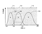
図5は、撮像素子243の画素が感度を有する波長帯と、構造化開口のそれぞれのフィルタ部が透過する波長帯の関係を示す図である。図は、縦軸に透過率(%)を、横軸に波長(nm)を示す。透過率が高い波長の光ほど、画素を構成するフォトダイオードに到達することを表す。
FIG. 5 is a diagram illustrating a relationship between a wavelength band in which a pixel of the
B曲線701は、B画素フィルタが設けられた画素の感度を示し、同様にG曲線702はG画素フィルタが設けられた画素の感度を、R曲線703はR画素フィルタが設けられた画素の感度を示す。構造化開口のBフィルタ部306は、矢印711の波長帯を透過させる。同様に、Gフィルタ部305は、矢印712の波長帯を透過させ、Rフィルタ部304は、矢印713の波長帯を透過させる。したがって、B画素フィルタが設けられた画素は、構造化開口のBフィルタ部306を透過した被写体光束に対して感度を持ち、G画素フィルタが設けられた画素は、構造化開口のGフィルタ部305を透過した被写体光束に対して感度を持ち、R画素フィルタが設けられた画素は、構造化開口のRフィルタ部304を透過した被写体光束に対して感度を持つと言える。
The
すると、Rフィルタ部304を開口とする赤色波長帯の被写体画像、Gフィルタ部305を開口とする緑色波長帯の被写体画像、およびBフィルタ部306を開口とする青色波長帯の被写体画像を、一度の撮影により取得することができる。これらの被写体画像は、それぞれ上述のIr、Ig、Ibに相当し、互いに三視点の視差画像を構成する。
Then, a subject image in the red wavelength band with the
なお、このように撮影される赤色波長帯の被写体画像、緑色波長帯の被写体画像および青色波長帯の被写体画像は、それぞれR画素フィルタが設けられた画素の出力のみ、G画素フィルタが設けられた画素の出力のみ、または、B画素フィルタが設けられた画素の出力のみを集めて互いに分離されるので、通常の撮影における画像処理とは異なる画像処理により形成される。したがって、ここでは通常の撮影により取得される撮影画像を本撮影画像と呼び、構造化開口を用いて取得される撮影画像を補助撮影画像と呼ぶ。本撮影画像は構造化開口ユニット300をレンズユニット210から抜出して撮影された画像であり、補助撮影画像は構造化開口ユニット300をレンズユニット210へ装着して撮影された画像である。
Note that the subject image of the red wavelength band, the subject image of the green wavelength band, and the subject image of the blue wavelength band captured in this manner are provided with the G pixel filter only for the output of the pixel provided with the R pixel filter. Since only pixel outputs or only pixel outputs provided with a B pixel filter are collected and separated from each other, they are formed by image processing different from image processing in normal photographing. Therefore, here, a captured image acquired by normal imaging is referred to as a main captured image, and a captured image acquired using the structured aperture is referred to as an auxiliary captured image. The actual captured image is an image captured by extracting the structured
次に、本実施形態に係る一眼レフカメラ200のシステム構成を説明する。図6は、一眼レフカメラ200のシステム構成を概略的に示すブロック図である。一眼レフカメラ200のシステムは、レンズユニット210とカメラユニット230のそれぞれに対応して、レンズシステム制御部216を中心とするレンズ制御系と、カメラシステム制御部245を中心とするカメラ制御系により構成される。そして、レンズ制御系とカメラ制御系は、レンズマウント218とカメラマウント231によって接続される接続部を介して、相互に各種データ、制御信号の授受を行う。
Next, the system configuration of the single-
カメラ制御系に含まれる画像処理部246は、カメラシステム制御部245からの指令に従って、撮像素子243で光電変換された撮像信号を画像データに処理する。本撮影画像において処理された画像データは、表示部247へ送られて、例えば撮影後の一定時間の間表示される。これに並行して、処理された画像データは、所定の画像フォーマットに加工され、外部接続IF254を介して外部メモリに記録される。画像処理部246は、補助撮影画像として撮影された撮像信号から、波長帯ごとに分離された被写体画像を生成する。生成された被写体画像は奥行き情報算出部251へ引き渡され、奥行き情報算出部251は、上述の手法により奥行き情報を算出する。算出された奥行き情報は、カメラメモリ252へ記録される。具体的な算出処理については後述する。
An
カメラメモリ252は、例えばフラッシュメモリなどの不揮発性メモリであり、生成された撮影画像の一時的な記録場所としての他に、一眼レフカメラ200を制御するプログラム、各種パラメータなどを記録する役割を担う。ワークメモリ253は、例えばRAMなどの高速アクセスできるメモリであり、処理中の画像データを一時的に保管する役割などを担う。
The
レリーズスイッチ255は押し込み方向に2段階のスイッチ位置を備えており、カメラシステム制御部245は、第1段階のスイッチであるSW1がONになったことを検出すると、AFセンサ240から位相差情報を取得する。そして、レンズシステム制御部216へフォーカスレンズ212の駆動情報を送信する。また、AEセンサ237から被写体像の輝度分布を取得して露出値を決定する。さらに、第2段階のスイッチであるSW2がONになったことを検出すると、予め定められた処理フローに従って本撮影画像の取得、または、補助撮影画像の取得を実行する。本撮影画像の取得と補助撮影画像の取得についての処理フローについては後述する。フラッシュ249は、カメラシステム制御部245の制御に従って被写体を照射する。
The
レンズシステム制御部216は、カメラシステム制御部245からの制御信号を受けて各種動作を実行する。また、レンズシステム制御部216は、位置センサ221からの出力を受けてフォーカスレンズ212の位置を検出する。レンズシステム制御部216は、焦点距離を含むレンズ情報と共に、検出したフォーカスレンズ位置をカメラシステム制御部245へ送信する。
The lens
次に、一眼レフカメラ200による撮影シーケンスの例を説明する。図7は、本撮影画像および補助撮影画像の取得フローを示す図である。撮影シーケンスが開始されると、カメラシステム制御部245は、ステップS301で、これから行う撮影動作が本撮影画像の撮影動作か、補助撮影画像の撮影動作かを判断する。本撮影画像の撮影動作であると判断したときは、ステップS302へ進む。
Next, an example of a shooting sequence by the single-
ステップS302でカメラシステム制御部245は、ユーザにより構造化開口ユニット300が被写体光束から抜出されているか否かを判断する。抜出さているか否かは、例えば、フォトインタラプタなどのセンサを設けて判断することができる。
In step S302, the camera
カメラシステム制御部245は、構造化開口ユニット300が抜出されたと判断したらステップS303へ進む。抜出されるまではステップS302で待機する。
If the camera
ステップS303では、カメラシステム制御部245は、レリーズスイッチ255のSW1がONにされるのを待って、被写体の測光を行う。具体的には、カメラシステム制御部245は、AEセンサ237から被写体像の輝度分布を取得する。カメラシステム制御部245は、被写体像の輝度分布を取得したら、ステップS304に進み、露出値を算出する。ここで、露出値とは、撮像素子243を被写体光束に露光する露光時間、被写体光束を制限する絞り214の絞り値、および撮像素子243の読み出しゲインに対応するISO感度の3つの数値である。
In step S303, the camera
また、カメラシステム制御部245は、SW1がONにされると、測光処理の他にも合焦動作などの撮影準備処理を実行する。合焦動作は、AFセンサ240を用いて被写体を測距し、得られた位相差情報に基づいて、レンズシステム制御部216がフォーカスレンズ212を駆動することにより実現される。
Further, when SW1 is turned on, the camera
撮影準備処理が終了すると、カメラシステム制御部245は、ステップS305へ進み、レリーズスイッチ255のSW2がONにされるのを待って、本撮影画像の取得動作を実行する。具体的には、メインミラー232およびサブミラー238を被写体光束から退避させ、決定された露出値に従って絞り214およびフォーカルプレーンシャッタ241を動作させる。さらに、フォーカルプレーンシャッタ241が開放されている間に撮像素子243の各画素に蓄積された電荷を読み出し、画像処理部246に予め設定されたフォーマットに従って画像ファイルを生成させ、当該画像ファイルを記録部に記録する。
When the shooting preparation process is completed, the camera
カメラシステム制御部245は、一連の本撮影画像の撮影動作が終了したらステップS306へ進み、引き続き補助撮影画像の撮影動作が指示されているか否かを判断する。補助撮影画像の撮影動作が指示されていなければ、一連の処理を終了する。
The camera
カメラシステム制御部245は、ステップS301またはステップS306で補助撮影画像の撮影動作が指示されていると判断したら、ステップS307へ進み、ユーザにより構造化開口ユニット300が被写体光束中に装着されているか否かを判断する。カメラシステム制御部245は、構造化開口ユニット300が装着されるまでステップS307で待機する。
If the camera
カメラシステム制御部245は、構造化開口ユニット300が装着されたと判断したらステップS308へ進む。補助撮影画像の撮影動作は、被写体光束中に構造化開口を介在させて実行するので、撮像素子243に到達する被写体光束の光学的条件が、本撮影画像の撮影動作時とは大きく異なる。簡単には、撮像素子243に到達する被写体光束が構造化開口によって制限されるので、本撮影画像の撮影条件と同じ条件では暗い画像が取得されることになる。そこで、カメラシステム制御部245は、補助撮影画像の撮影条件を、本撮影画像の撮影条件とは異ならせる。
If the camera
そこで、カメラシステム制御部245は、補助撮影画像の撮影動作時にフラッシュ249を動作させて被写体を照射する。カメラシステム制御部245は、ステップS308へ進むと、SW1がONにされるのを待って、フラッシュ249の事前照射動作であるプリ発光を行い、被写体の測光を行う。具体的には、カメラシステム制御部245は、AEセンサ237から被写体像のプリ発光時における輝度分布を取得する。
Therefore, the camera
また、カメラシステム制御部245は、SW1がONにされると、測光処理の他にも合焦動作などの撮影準備処理を実行する。合焦動作は、AFセンサ240を用いて被写体を測距し、得られた位相差情報に基づいて、レンズシステム制御部216がフォーカスレンズ212を駆動することにより実現される。このとき、レンズユニット210のレンズ情報、合焦動作を行った測距点、その他の測距点におけるデフォーカス量、フォーカスレンズ位置などを含む測距情報は、一旦ワークメモリ253に保管される。
Further, when SW1 is turned on, the camera
カメラシステム制御部245は、被写体像の輝度分布を取得したら、ステップS309へ進み、露出値を算出する。このときの露出値はフラッシュ249の発光を前提とした値であり、したがって、カメラシステム制御部245は、ステップS310へ進み、撮影動作時におけるフラッシュ249の照射量を決定する。なお、照射量の算出は、AEセンサ237から得られる輝度分布情報から行っても良いが、本撮影画像の撮影動作時にもフラッシュ249を照射させたのであれば、当該撮影動作時における照射量から、補助撮影画像の撮影動作における照射量を算出しても良い。具体的には、構造化開口を被写体光束中に介在させることによりカットされる光量は事前の実験等により把握されるので、これに応じて低下する露出段数分に相当する光量を本撮影画像の撮影動作時における照射量に足して算出する。
After acquiring the luminance distribution of the subject image, the camera
なお、ステップS309における露出値の算出は、ステップS310のフラッシュ249の照射量の決定とセットで実行されるが、露出値のうちISO感度については、ステップS304で算出されるISO感度よりも大きく設定すると良い。すなわち、補助撮影画像における被写体のぶれは、奥行き情報の算出に悪影響を及ぼし精度の低下を招くので、撮像素子243に対する露光時間は短いことが好ましい。そこで、露光時間を短くすべく、ISO感度を大きく設定する。補助撮影画像はユーザの鑑賞画像ではないので、奥行き情報の算出に影響しない限りにおいてISO感度が大きく設定されても良い。したがって、カメラシステム制御部245が設定し得るISO感度の上限は、本撮影画像の撮影動作時の値と補助撮影画像の撮影動作時の値で異なり、補助撮影画像の撮影動作時の値の方が大きい。
Note that the calculation of the exposure value in step S309 is executed in combination with the determination of the irradiation amount of the
このように撮影動作時における露出値と照射量が決定されると、カメラシステム制御部245は、ステップS311へ進み、レリーズスイッチ255のSW2がONにされるのを待って、補助撮影画像の取得動作を実行する。具体的には、メインミラー232およびサブミラー238を被写体光束から退避させ、決定された露出値に従って絞り214およびフォーカルプレーンシャッタ241を動作させる。このとき、決定された照射量に従ってフラッシュ249を動作させ被写体を照射する。さらに、撮像素子243の各画素に蓄積された電荷を読み出し、画像処理部246に赤色画像、緑色画像および青色画像の3つの視差画像を含む補助撮影画像ファイルを生成させ、当該画像ファイルを記録部に記録する。同時に、測距情報を当該補助撮影画像に関連付けて記録する。測距情報は、例えば、付帯情報であるEXIF情報として記述される。以上により一連の処理を終了する。
When the exposure value and the irradiation amount during the photographing operation are determined in this way, the camera
また、本フローにおいては、補助撮影画像の撮影動作時にフラッシュ249を照射させて構造化開口による光量低下を補った。しかし、被写体環境によってはフラッシュ249を照射させずに他の撮影条件を変更することにより光量低下を補っても良い。例えば、上述のように、ISO感度を大きな値に設定する。または、予め定められた露光時間を下限として、露光時間を長めに設定しても良い。つまり、カメラシステム制御部245は、本撮影画像の撮影条件に比較して、補助撮影画像の撮影条件を、被写体光束をより取り込む、取り込んだ光をより増幅する方向に変更すればよい。
Further, in this flow, the
次に、AFセンサ240の出力に基づく、距離情報の取得について説明する。図8は、光学ファインダから観察される被写体像および測距領域を示す図である。なお、ここではシーンの例として、手前から順に少女101、少年102および女性103が存在する場合を説明する。
Next, acquisition of distance information based on the output of the
AFセンサ240は、被写体空間に対して二次元的かつ離散的に配置される複数の測距点260を有する。図の例の場合、11点の測距点260が、全体として略菱形形状に離散的に配置されている。AFセンサ240は、それぞれの測距点260に対応するデフォーカス量を独立に出力することができる。
The
カメラシステム制御部245は、例えば近点優先等のアルゴリズムにより選択された合焦測距点261のデフォーカス量を検出して、合焦に至るフォーカスレンズ212の移動量および移動方向を決定し、レンズシステム制御部216へ送信する。レンズシステム制御部216は、これらの情報に従ってフォーカスレンズ212を移動させる。フォーカスレンズ212の移動が完了すると、カメラシステム制御部245は、AFセンサ240により合焦測距点261のデフォーカス量を再度検出して、合焦測距点261に対応するオブジェクトにピントが合ったことを確認する。
The camera
カメラシステム制御部245は、ピントが合ったことを確認できたら、スーパーインポーズ表示等により合焦測距点261を明滅させ、合焦動作完了をユーザに告知する。また、カメラシステム制御部245は、合焦測距点261のデフォーカス量を再度検出すると同時に、他の測距点260のデフォーカス量も検出する。このとき、ほぼ同じデフォーカス量を示す測距点260ごとにグルーピングする。図の場合、第1デフォーカス量を示す第1非合焦測距点262、および第2デフォーカス量を示す第2非合焦測距点263を別々のグループとして認識する。なお、特定のグループのデフォーカス量から一定の範囲内にあるデフォーカス量を示す測距点260、および無限遠のデフォーカス量を示す測距点260は、グルーピングの対象外とする。なお、合焦測距点261が複数存在すれば、これらを纏めてグループとして認識する。
When the camera
これらグルーピングされた測距点260に対応する被写体空間には、被写体としてのオブジェクトがそれぞれ存在する。図の例によれば、合焦測距点261に対応して少女101が、第1非合焦測距点262に対応して少年102が、第2非合焦測距点263に対応して女性103が存在している。
In the subject space corresponding to the grouped
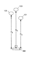
カメラシステム制御部245は、これらのグルーピング情報を含む測距情報から、それぞれのオブジェクトまでの距離を算出する。図9は、取得されるオブジェクト距離を説明する図である。
The camera
各オブジェクトまでの距離は、一眼レフカメラ200に配設された撮像素子243の受光面を基準として算出される。例えば、少年102までの距離DBは、第1非合焦測距点262におけるデフォーカス量、レンズユニット210のレンズ情報、フォーカスレンズ位置等から算出される。より具体的には、レンズ情報として、フォーカスレンズ位置と合焦オブジェクト距離の対応テーブルを取得し、現在のフォーカスレンズ位置を入力することにより、合焦オブジェクトまでの距離を得る。この距離は少女101までの距離DAに相当する。
The distance to each object is calculated with reference to the light receiving surface of the
オートフォーカスにおいては、あるデフォーカス量に対して、合焦位置までフォーカスレンズ212をどれだけ移動させればよいかの移動量変換関数を利用している。そこで、ここでもこの移動量関数を利用して、第1非合焦測距点262におけるデフォーカス量から、フォーカスレンズ212の移動量を算出する。そして、現在のフォーカスレンズ位置に算出した移動量を加算した値を対応テーブルに入力することにより、距離DBを得る。
In autofocus, a movement amount conversion function for how much the
女性103までの距離DCも同様に算出できる。この場合、第2非合焦測距点263には3つの測距点260が含まれるが、いずれか1つの測距点260におけるデフォーカス量を代表として用いれば良い。グルーピングしたそれぞれに対してオブジェクト距離を算出したら、その算出したオブジェクト距離とグルーピングした測距点260の配置とをペアとして記録する。
Distance D C to
なお、移動量変換関数を利用して非合焦測距点に対応するオブジェクトまでの距離を算出する場合は、当該関数を補助撮影画像の関連情報として保持しておく。また、移動量変換関数を利用しなくても、レンズ情報としてレンズユニット210の焦点距離、測距時における絞り値、および第1非合焦測距点262におけるデフォーカス量を取得すれば、デフォーカスに相当する距離を算出できる。この場合は、合焦オブジェクトまでの距離に算出した距離を加算して非合焦オブジェクトまでの距離を得る。
Note that when the distance to the object corresponding to the out-of-focus distance measuring point is calculated using the movement amount conversion function, the function is held as related information of the auxiliary captured image. Even if the movement amount conversion function is not used, if the focal length of the
次に、これらの距離情報を用いて行うマッチング処理について説明する。図10は、オブジェクト領域と局所ウィンドウの関係を示す概念図である。図は、左から順に、補助撮影画像から抽出されるIr画像、Ig画像、Ib画像を表す。これらは互いに視差画像である。少女101に対応する画像領域は、ピントが合っている領域なので、互いに視差が無い。一方、少年102に対応する画像領域および女性103に対応する画像領域は、ピントが合っていない領域なので、互いに視差がある。特に、少年102よりも女性103の方が少女101から遠い距離に存在するので、女性103に対応する画像領域の視差量の方が少年102に対応する画像領域の視差量よりも大きいと推測される。
Next, the matching process performed using these distance information will be described. FIG. 10 is a conceptual diagram showing the relationship between the object area and the local window. Figure, in order from the left, I r image extracted from the auxiliary captured image, I g images, representing a I b images. These are mutually parallax images. Since the image area corresponding to the
すでに説明した奥行き情報の取得原理によれば、それぞれの画像間における同一オブジェクトの視差量を算出することにより、当該オブジェクトの距離と輪郭を演算する。視差量の算出は、局所ウィンドウをそれぞれの視差画像に設定して、相対的にずらしながら互いにマッチングの良い画像領域を探索することにより実行する。そして、互いにマッチングが良いと判断される座標値から視差量を決定する。このとき、設定する局所ウィンドウのウィンドウサイズが視差量に対して大き過ぎると、境界部分の分解能が低下して結果的には曖昧な輪郭を定義することになり、逆に小さすぎると誤った領域に対してマッチングが良いと判断する誤対応が増加する。したがって、適切なウィンドウサイズを規定しなければ、精度の高い輪郭を定めることができない。 According to the depth information acquisition principle already described, the distance and contour of the object are calculated by calculating the parallax amount of the same object between the images. The calculation of the amount of parallax is performed by setting a local window for each parallax image and searching for image regions with good matching with each other while relatively shifting. Then, the amount of parallax is determined from the coordinate values that are determined to match each other. At this time, if the window size of the local window to be set is too large with respect to the amount of parallax, the resolution of the boundary portion will be reduced, resulting in the definition of an ambiguous contour. Mismatches that determine that matching is good increase. Therefore, a high-precision contour cannot be defined unless an appropriate window size is defined.
そこで、本実施形態においては、AFセンサ240の出力から算出した上述の距離情報を利用して、それぞれのオブジェクトに最適と考えられるウィンドウサイズを決定する。距離情報は、グルーピングした測距点260の配置と対応するオブジェクトの距離を含むので、まず測距点260の配置に対応する画像位置を取り囲む領域をオブジェクト領域として定義する。図の例においては、合焦測距点261に対応するオブジェクト領域として合焦オブジェクト領域271、第1非合焦測距点262に対応するオブジェクト領域として第1非合焦オブジェクト領域272、第2非合焦測距点263に対応するオブジェクト領域として第2非合焦オブジェクト領域273を定義する。
Therefore, in the present embodiment, the window size considered to be optimal for each object is determined using the above-described distance information calculated from the output of the
そして、合焦オブジェクト領域271においては、一辺の長さがWAの正方形である局所ウィンドウ281をそれぞれの視差画像で上下左右に移動させてマッチング処理を行う。同様に、第1非合焦オブジェクト領域272においては、一辺の長さがWBの正方形である局所ウィンドウ282をそれぞれの視差画像で上下左右に移動させ、第2非合焦オブジェクト領域273においては、一辺の長さがWCの正方形である局所ウィンドウ283をそれぞれの視差画像で上下左右に移動させて、マッチング処理を行う。
Then, at a
合焦オブジェクト領域271においては視差画像間に視差が存在しないことが予想されるので、局所ウィンドウ281におけるウィンドウサイズWAは、合焦オブジェクト領域に対するウィンドウサイズとして予め定められたサイズが適用される。一方、第1非合焦オブジェクト領域272においては視差画像間に、距離差|DB−DA|に基づく視差量が存在することが想定されるので、局所ウィンドウ282におけるウィンドウサイズWBは、距離差|DB−DA|から算出されるサイズが適用される。同様に、第2非合焦オブジェクト領域273においても視差画像間に、距離差|DC−DA|に基づく視差量が存在することが想定されるので、局所ウィンドウ283におけるウィンドウサイズWCは、距離差|DC−DA|から算出されるサイズが適用される。具体的な算出手順については後述する。
Because the
このようにしてマッチング処理が行われると、それぞれのオブジェクトに対する輪郭が定められ、いわゆる距離画像を生成することができる。図11は、出力される距離画像の概念を説明する図である。 When the matching process is performed in this manner, the contour for each object is determined, and a so-called distance image can be generated. FIG. 11 is a diagram for explaining the concept of the output distance image.
図示するように、被写体として存在するオブジェクトごとに輪郭が定められ、それぞれの輪郭に内包する領域がほぼ同じ距離に存在することを表す。少女101に対応する画像領域としての領域Aには、距離DAが関連付けられている。同様に、少年102に対応する画像領域としての領域Bには、距離DBが関連付けられ、女性103に対応する画像領域としての領域Cには、距離DCが関連付けられている。また、その他の領域である領域Dの距離は無限遠として関連付けられる。
As shown in the figure, a contour is defined for each object that exists as a subject, indicating that the regions included in each contour are present at substantially the same distance. A distance DA is associated with an area A as an image area corresponding to the
なお、図示する距離画像に対しては、3つの視差画像のいずれかを基準として輪郭を定めても良いし、3つの視差画像の重心により規定される視差の無い仮想的な画像を基準として輪郭を定めても良い。また、対応する本撮影画像に対応させて輪郭を定めても良い。 Note that for the distance image shown in the figure, the contour may be defined based on one of the three parallax images, or the contour image based on a virtual image having no parallax defined by the center of gravity of the three parallax images. May be determined. Further, the contour may be determined in correspondence with the corresponding main captured image.
奥行き情報算出部251は、このようにして算出した奥行き情報を、図11で示すようなオブジェクトの輪郭とそれに対応する距離により定義された距離画像として出力することもできるし、オブジェクトごとに輪郭を定めるベクトルデータと対応する距離とを列挙した、オブジェクトテーブルとして出力することもできる。
The depth
次に、距離差に基づいてウィンドウサイズを決定する算出手順について説明する。図12は、オブジェクトと視差量の関係を表す概念図である。なお、ここでは主光線がレンズ群211の瞳の中心を通ると仮定する。
Next, a calculation procedure for determining the window size based on the distance difference will be described. FIG. 12 is a conceptual diagram showing the relationship between an object and the amount of parallax. Here, it is assumed that the chief ray passes through the center of the pupil of the
フォーカスレンズ212が特定のオブジェクトに焦点を合せた場合の、そのフォーカス位置に存在する合焦オブジェクトまでの距離をsとする。また、デフォーカス位置に存在する非合焦オブジェクトまでの距離をs1とする。そして、レンズユニット210の焦点距離をfとし、絞り値をFとすれば、s1にある非合焦オブジェクトの撮像素子243上に現れる視差量εは、

視差量εは、式(2)から、非合焦オブジェクトごとに算出され得ることがわかる。したがって、非合焦オブジェクト領域ごとにεを算出できるので、それぞれの非合焦オブジェクト領域に対して、視差量εに相当するピクセルサイズをウィンドウサイズとして規定する局所ウィンドウを適用できる。 It can be seen from the equation (2) that the parallax amount ε can be calculated for each out-of-focus object. Therefore, since ε can be calculated for each non-focused object region, a local window that defines a pixel size corresponding to the parallax amount ε as a window size can be applied to each non-focused object region.
図13は、補助撮影画像の取得から奥行き情報の出力までの処理フローを示す図である。本フローにおける一連の処理は、カメラシステム制御部245が操作部材を介してユーザから指示を受け付けたとき、または、予め定められた制御プログラムに距離算出処理が組み込まれているとき等に開始される。
FIG. 13 is a diagram illustrating a processing flow from acquisition of an auxiliary captured image to output of depth information. A series of processes in this flow is started when the camera
ステップS101では、画像処理部246が処理対象となる補助撮影画像を取得する。画像処理部246は、処理対象の補助撮影画像として、撮像素子243から出力された画像信号をそのまま取得しても良いし、撮影後に奥行き情報を算出しないまま記録部に記録されている補助撮影画像を読み出して取得しても良い。したがって、本実施形態においてはカメラユニット230を画像演算装置として奥行き情報の算出を実行するが、奥行き情報の算出は、カメラとは別個の独立した画像演算装置で実行することもできる。
In step S101, the
例えば、PCを例にすれば、カメラとの間に記録媒体を介在させ、記録媒体に記録された補助撮影画像を読み出して処理することもできるし、有線、無線によりカメラと接続した状態を確立すれば、補助撮影画像の撮影と連動して処理することもできる。この場合は、補助撮影画像に関連付けられた、または一体的に記録された、AFセンサ240の出力に基づく距離情報も、補助撮影画像と共に画像演算装置に取り込む。また、演算の方式に応じて、補助撮影画像の撮影時におけるレンズユニット210のレンズ情報、移動量変換関数等も画像演算装置に取り込む。
For example, taking a PC as an example, a recording medium can be interposed between the camera and an auxiliary captured image recorded on the recording medium can be read and processed, or a state where the camera is connected to the camera by wire or wirelessly can be established. If so, processing can be performed in conjunction with the shooting of the auxiliary captured image. In this case, distance information based on the output of the
距離情報については、AFセンサ240の出力に基づく距離情報でなくても、合焦オブジェクトまでの距離、非合焦オブジェクトまでの距離がそれぞれ少なくとも1つ以上含まれる距離情報であれば、いかなる取得方式により取得されたものであっても良い。オブジェクトまでの距離は様々な取得方式が知られているが、例えば、赤外線投射型のアクティブ測距方式等が利用できる。なお、以下のフローにおいては、すでに説明したように、オブジェクト距離とグルーピングした測距点260の配置とがペアとして記録された距離情報を例に説明する。
As for the distance information, any acquisition method may be used as long as the distance information includes at least one distance to the in-focus object and at least one distance to the non-focus object, even if the distance information is not based on the output of the
画像処理部246は、ステップS102で、補助撮影画像から、Rフィルタ部304を通過して形成された赤色画像、すなわち、R画素フィルタが設けられた画素の出力から形成されるIr画像を抽出する。同様に、Gフィルタ部305を通過して形成された緑色画像であるIg画像とBフィルタ部306を通過して形成された青色画像であるIb画像を抽出する。画像処理部246は、このように波長帯別画像を抽出すると、これらの画像を奥行き情報算出部251へ引き渡す。
The
奥行き情報算出部251は、ステップS103で、距離情報を抽出する。距離情報として取得した情報が、測距情報等の未だ距離に換算される前の状態であれば、ここでそれぞれのオブジェクトまでの距離を算出する。また、奥行き情報算出部251は、オブジェクト距離とグルーピングした測距点260の配置によるペアがいくつあるかをカウントし、変数nに代入する。
In step S103, the depth
奥行き情報算出部251は、ステップS104へ進み、インクリメント変数iを1とする。そして、ステップS105へ進み、i番目のペアに対応するオブジェクトOiについて、上述の手順によりオブジェクト領域とウィンドウサイズを決定する。
The depth
奥行き情報算出部251は、ステップS105へ進み、決定したオブジェクト領域付近において、決定したウィンドウサイズにより規定した局所ウィンドウを用いてオブジェクトOiに対する境界を確定する。この段階では、隣接するオブジェクトに対して境界が確定していないので、まだ境界間の調整がなされておらず、その意味においてオブジェクトの輪郭は定まっていない。
The depth
奥行き情報算出部251は、ステップS107でインクリメント変数iをインクリメントしてステップS108へ進む。ステップS108では、インクリメント変数iが変数nより大きいか否かを判断する。つまり、距離情報として取得したペアの全てについて処理が完了したか否かを判断する。条件を満たさなければステップS105へ戻り、満たせばステップS109へ進む。
The depth
奥行き情報算出部251は、ステップS109で、それぞれのオブジェクトに対して確定した境界が互いに交差しているかなどの不整合が無いかを確認し、不整合箇所を調整する。不整合箇所の調整は、例えば近点側のオブジェクトを優先するなどの、予め定められたアルゴリズムに従って実行される。境界の調整が終了すれば、それを輪郭情報として確定し、ステップS110で奥行き情報として出力する。
In step S109, the depth
奥行き情報は、距離画像データとして別途独立したファイルを生成しても良いし、補助撮影画像に付帯して記録しても良い。別途独立したファイルを生成する場合には、補助撮影画像に対してリンク情報を記録する。もちろん、上述のように、オブジェクトごとに輪郭を定めるベクトルデータと対応する距離とを列挙した、オブジェクトテーブルとして出力することもできる。以上により一連の処理フローを終了する。 For the depth information, a separate file may be generated as the distance image data, or the auxiliary information may be recorded with the auxiliary captured image. When a separate file is generated separately, link information is recorded for the auxiliary captured image. Of course, as described above, it is also possible to output as an object table in which vector data for defining an outline for each object and corresponding distances are listed. A series of processing flow is complete | finished by the above.
次に、上記処理フローの変形例を説明する。上述の処理においては、取得した距離情報からオブジェクト間の距離差を算出し、この距離差に起因する視差量からウィンドウサイズを演算して局所ウィンドウを規定した。本変形例においては、予め設定された複数のウィンドウサイズにより局所ウィンドウを規定し、それぞれの局所ウィンドウによって視差画像の全領域に対してオブジェクトの距離と境界を抽出する演算を行う。このようにして抽出された、あるオブジェクトに対する複数の距離のうち、取得した距離情報と最も一致する演算結果を得た局所ウィンドウによる境界を、当該オブジェクトの境界と定める。以下にその処理フローを説明する。 Next, a modified example of the processing flow will be described. In the above processing, the distance difference between objects is calculated from the acquired distance information, and the window size is calculated from the amount of parallax caused by the distance difference to define the local window. In this modification, a local window is defined by a plurality of window sizes set in advance, and an operation for extracting the distance and boundary of an object is performed on the entire region of the parallax image by each local window. Of the plurality of distances with respect to a certain object extracted in this way, the boundary by the local window that obtains the operation result that most closely matches the acquired distance information is determined as the boundary of the object. The processing flow will be described below.
図14は、補助撮影画像の取得から奥行き情報の出力までの他の処理フローを示す図である。ステップS201では、画像処理部246が処理対象となる補助撮影画像を取得する。画像処理部246は、ステップS102で、補助撮影画像からIr、Ig、Ibの各視差画像を抽出し、奥行き情報算出部251へ引き渡す。奥行き情報算出部251は、ステップS203で、距離情報を抽出すると共に、オブジェクト距離とグルーピングした測距点260の配置によるペアがいくつあるかをカウントし、変数nに代入する。
FIG. 14 is a diagram illustrating another processing flow from acquisition of an auxiliary captured image to output of depth information. In step S201, the
画像処理部246は、ステップS204で、インクリメント変数jを1とする。そして、ステップS205へ進み、予め設定されたm個のウィンドウサイズのうち、j番目のウィンドウサイズであるWjにより規定した局所ウィンドウで各視差画像の全体領域を探索し、各オブジェクトの距離および境界を演算する。なお、この段階におけるウィンドウサイズは、視差量に対して適切なサイズではないものを含むので、上述のように、演算結果には誤差等を含み得る。
In step S204, the
奥行き情報算出部251は、ステップS206でインクリメント変数jをインクリメントしてステップS207へ進む。ステップS207では、インクリメント変数jが変数mより大きいか否かを判断する。つまり、予め設定されたm個のウィンドウサイズの全てについて演算が完了したか否かを判断する。条件を満たさなければステップS205へ戻り、満たせばステップS208へ進む。
The depth
奥行き情報算出部251は、ステップS208で、インクリメント変数iを1とする。そして、ステップS209へ進み、i番目のペアに対応するオブジェクトOiについて、ステップS205において演算されたm個の距離と、距離情報によるオブジェクト距離を対比する。
The depth
奥行き情報算出部251は、ステップS210へ進み、演算されたm個の距離のうち距離情報によるオブジェクト距離Diと最も近いものを選択し、これを算出したウィンドウサイズWj0によって演算されたオブジェクトOi近傍の境界を、オブジェクトOi近傍の境界として確定する。
Depth
奥行き情報算出部251は、ステップS211でインクリメント変数iをインクリメントしてステップS212へ進む。ステップS212では、インクリメント変数iが変数nより大きいか否かを判断する。つまり、距離情報として取得したペアの全てについて処理が完了したか否かを判断する。条件を満たさなければステップS208へ戻り、満たせばステップS213へ進む。
The depth
奥行き情報算出部251は、ステップS213で、それぞれのオブジェクトに対して確定した境界が互いに交差しているかなどの不整合が無いかを確認し、不整合箇所を調整する。境界の調整が終了すれば、それを輪郭情報として確定し、ステップS214で奥行き情報として出力する。以上により一連の処理フローを終了する。
In step S213, the depth
以上の実施形態においては、AFセンサ240の測距点に応じて合焦オブジェクトと非合焦オブジェクトを決定したが、複数のオブジェクトのうち少なくとも一つを、操作部材を介してユーザに指定させるように構成しても良い。この場合、奥行き情報算出部251は、ユーザによって指定されたオブジェクトに対してウィンドウサイズを決定し、奥行き情報の演算を実行する。
In the above embodiment, the in-focus object and the out-of-focus object are determined according to the distance measuring point of the
また、以上の実施形態においては、一眼レフカメラを例に説明したが、光学ファインダを持たないレンズ交換式カメラ、レンズユニットが一体化されたコンパクトカメラ、動画撮影を行うこともできるビデオカメラといった撮像装置に対しても適用することができる。 In the above embodiments, a single-lens reflex camera has been described as an example. However, imaging such as an interchangeable lens camera without an optical finder, a compact camera with an integrated lens unit, and a video camera that can also shoot moving images. It can also be applied to a device.
また、以上の実施形態においては、撮像素子としてベイヤー配列のカラーフィルタを有する単板式撮像素子を例に説明したが、他のカラーフィルタ配列であっても良く、さらには、RGBに限らず他の波長帯を透過させるフィルタが配列されていても良い。この場合、構造化開口のフィルタ部は、撮像素子のカラーフィルタの波長帯に応じて透過波長帯が選択される。 In the above embodiment, a single-plate image sensor having a Bayer array color filter as an image sensor has been described as an example. However, other color filter arrays may be used, and not limited to RGB. A filter that transmits the wavelength band may be arranged. In this case, the transmission wavelength band is selected for the filter portion of the structured aperture according to the wavelength band of the color filter of the image sensor.
また、カラーフィルタを持たず、フォトダイオードの奥行き方向に異なる感応波長帯を有する撮像素子に対しても適用できる。この場合、構造化開口のフィルタ部は、フォトダイオードの奥行き方向で分離される波長帯に応じて透過波長帯が選択される。さらには、単板の撮像素子を備えるカメラに限らず、例えばRGBのそれぞれに分けられた三板式カメラのような、入射する被写体光束を複数の波長帯に分離してそれぞれの波長帯を独立して受光する複数の撮像素子を備えるカメラに対しても適用することができる。また、RGBのうち2つの波長帯を透過させるフィルタが配列されていれば、上述の距離情報取得を行うことができるので、以上の実施形態に係る構造化開口のRGBフィルタのうちの一つを取り除いても良い。 Further, the present invention can be applied to an image pickup element that does not have a color filter and has different sensitive wavelength bands in the depth direction of the photodiode. In this case, the transmission wavelength band is selected for the filter portion of the structured aperture according to the wavelength band separated in the depth direction of the photodiode. Furthermore, the present invention is not limited to a camera having a single-plate image sensor, but separates the incident light flux into a plurality of wavelength bands, such as a three-plate camera divided into RGB, for example, to make each wavelength band independent. The present invention can also be applied to a camera including a plurality of image sensors that receive light. Moreover, if the filter which transmits two wavelength bands among RGB is arranged, the above-mentioned distance information acquisition can be performed, so one of the RGB filters of the structured aperture according to the above embodiment is It may be removed.
また、取得する距離情報は、カメラから各オブジェクトまでの絶対距離でなくても良い。この場合、合焦オブジェクトから非合焦オブジェクトまでの相対距離が取得されれば、視差量に基づくウィンドウサイズが決定できる。また、取得する距離情報を用いて非合焦オブジェクト間の距離を算出し、奥行き情報の演算結果の確からしさを評価する評価演算に利用しても良い。 Further, the acquired distance information may not be the absolute distance from the camera to each object. In this case, if the relative distance from the focused object to the non-focused object is acquired, the window size based on the parallax amount can be determined. Further, the distance information between the out-of-focus objects may be calculated using the acquired distance information, and may be used for an evaluation calculation for evaluating the certainty of the calculation result of the depth information.
また、以上の実施例においては、オブジェクトの距離差に対応して算出される視差量に基づいてウィンドウサイズを決定したが、オブジェクト領域内で適用するウィンドウサイズは多少の許容範囲を有する。具体的には、当該ウィンドウサイズ内で局所ウィンドウを移動させるときに、その位置において局所ウィンドウ内にオブジェクトの境界が含まれない場合は、境界が含まれない限りにおいてウィンドウサイズを拡大しても良い。したがって、境界が複雑形状であるオブジェクトに対しては、ウィンドウサイズを拡大できる範囲が小さい。 In the above embodiment, the window size is determined based on the parallax amount calculated corresponding to the object distance difference. However, the window size applied in the object area has some tolerance. Specifically, when the local window is moved within the window size, if the boundary of the object is not included in the local window at the position, the window size may be enlarged as long as the boundary is not included. . Therefore, the range in which the window size can be enlarged is small for an object having a complicated boundary.
以上、本発明を実施の形態を用いて説明したが、本発明の技術的範囲は上記実施の形態に記載の範囲には限定されない。上記実施の形態に、多様な変更または改良を加えることが可能であることが当業者に明らかである。その様な変更または改良を加えた形態も本発明の技術的範囲に含まれ得ることが、特許請求の範囲の記載から明らかである。 As mentioned above, although this invention was demonstrated using embodiment, the technical scope of this invention is not limited to the range as described in the said embodiment. It will be apparent to those skilled in the art that various modifications or improvements can be added to the above-described embodiment. It is apparent from the scope of the claims that the embodiments added with such changes or improvements can be included in the technical scope of the present invention.
特許請求の範囲、明細書、および図面中において示した装置、システム、プログラム、および方法における動作、手順、ステップ、および段階等の各処理の実行順序は、特段「より前に」、「先立って」等と明示しておらず、また、前の処理の出力を後の処理で用いるのでない限り、任意の順序で実現しうることに留意すべきである。特許請求の範囲、明細書、および図面中の動作フローに関して、便宜上「まず、」、「次に、」等を用いて説明したとしても、この順で実施することが必須であることを意味するものではない。 The order of execution of each process such as operations, procedures, steps, and stages in the apparatus, system, program, and method shown in the claims, the description, and the drawings is particularly “before” or “prior to”. It should be noted that the output can be realized in any order unless the output of the previous process is used in the subsequent process. Regarding the operation flow in the claims, the description, and the drawings, even if it is described using “first”, “next”, etc. for convenience, it means that it is essential to carry out in this order. It is not a thing.
101 少女、102 少年、103 女性、200 一眼レフカメラ、201 光軸、210 レンズユニット、211 レンズ群、212 フォーカスレンズ、213 ズームレンズ、214 絞り、216 レンズシステム制御部、217 レンズ鏡筒、218 レンズマウント、219 装着スリット、220 挿抜ガイド、221 位置センサ、230 カメラユニット、231 カメラマウント、232 メインミラー、233 回転軸、234 ピント板、235 ペンタプリズム、236 接眼光学系、237 AEセンサ、238 サブミラー、239 AF光学系、240 AFセンサ、241 フォーカルプレーンシャッタ、242 光学ローパスフィルタ、243 撮像素子、244 メイン基板、245 カメラシステム制御部、246 画像処理部、247 表示部、248 二次電池、249 フラッシュ、251 奥行き情報算出部、252 カメラメモリ、253 ワークメモリ、254 外部接続IF、255 レリーズスイッチ、260 測距点、261 合焦測距点、262 第1非合焦測距点、263 第2非合焦測距点、271 合焦オブジェクト領域、272 第1非合焦オブジェクト領域、273 第2非合焦オブジェクト領域、281、282、283 局所ウィンドウ、300 構造化開口ユニット、302 フィルタ、303 遮断フィルタ部、304 Rフィルタ部、305 Gフィルタ部、306 Bフィルタ部、307 ベース部、308 外周部、309 把持部、701 B曲線、702 G曲線、703 R曲線、711、712、713 矢印 101 Girl, 102 Boy, 103 Woman, 200 Single-lens reflex camera, 201 Optical axis, 210 Lens unit, 211 Lens group, 212 Focus lens, 213 Zoom lens, 214 Aperture, 216 Lens system control unit, 217 Lens barrel, 218 lens Mount, 219 Mounting slit, 220 Insertion / extraction guide, 221 Position sensor, 230 Camera unit, 231 Camera mount, 232 Main mirror, 233 Rotating shaft, 234 Focus plate, 235 Pentaprism, 236 Eyepiece optical system, 237 AE sensor, 238 Sub mirror, 239 AF optical system, 240 AF sensor, 241 focal plane shutter, 242 optical low-pass filter, 243 image sensor, 244 main board, 245 camera system control unit, 246 Image processing unit, 247 display unit, 248 secondary battery, 249 flash, 251 depth information calculation unit, 252 camera memory, 253 work memory, 254 external connection IF, 255 release switch, 260 distance measuring point, 261 focusing distance measuring point 262, first out-of-focus distance measuring point, 263 second out-of-focus distance measuring point, 271 in-focus object area, 272 first out-of-focus object area, 273 second out-of-focus object area, 281, 282, 283 Local window, 300 structured aperture unit, 302 filter, 303 blocking filter section, 304 R filter section, 305 G filter section, 306 B filter section, 307 base section, 308 outer peripheral section, 309 gripping section, 701 B curve, 702 G Curve, 703 R curve, 711, 712, 713 Arrow
Claims (8)
前記視差画像データにおいて合焦状態にある少なくとも一つの合焦物体までの距離情報と非合焦状態にある少なくとも一つの非合焦物体までの距離情報を取得する距離情報取得部と、
前記距離情報に基づくウィンドウサイズにより規定される局所ウィンドウを用いて前記視差画像データ間のマッチング処理を行うことにより、前記視差画像に含まれる複数の物体に対して奥行き方向に分離して輪郭を定める演算部と
を備える画像演算装置。 An image acquisition unit that outputs parallax image data that is output from a light receiving element that detects and separates incident subject light flux into a plurality of wavelength bands, and images corresponding to at least two of the plurality of wavelength bands have a parallax;
A distance information acquisition unit that acquires distance information to at least one in-focus object in the in-focus state and distance information to at least one in-focus object in the in-focus state in the parallax image data;
By performing a matching process between the parallax image data using a local window defined by a window size based on the distance information, a plurality of objects included in the parallax image are separated in the depth direction to define an outline. An image calculation device comprising a calculation unit.
前記演算部は、前記ユーザによって指定された前記複数の物体のうちの少なくとも一つに対して前記ウィンドウサイズを決定する請求項1から4のいずれか1項に記載の画像演算装置。 A designation unit that allows a user to designate at least one of the plurality of objects;
The image calculation device according to claim 1, wherein the calculation unit determines the window size for at least one of the plurality of objects specified by the user.
前記演算部は、前記グループ情報に基づいて複数の前記ウィンドウサイズを決定する請求項6に記載の画像演算装置。 The distance information includes group information in which a plurality of focal points of the AF sensor are divided into a plurality of groups based on the output,
The image calculation device according to claim 6, wherein the calculation unit determines a plurality of window sizes based on the group information.
前記視差画像データにおいて合焦状態にある少なくとも一つの合焦物体までの距離情報と非合焦状態にある少なくとも一つの非合焦物体までの距離情報を取得する距離情報取得ステップと、
前記距離情報に基づくウィンドウサイズにより規定される局所ウィンドウを用いて前記視差画像データ間のマッチング処理を行うことにより、前記視差画像に含まれる複数の物体に対して奥行き方向に分離して輪郭を定める演算ステップと
をコンピュータに実行させる画像演算プログラム。 An image acquisition step of acquiring parallax image data output from a light receiving element that detects and splits an incident subject luminous flux into a plurality of wavelength bands, and images corresponding to at least two of the plurality of wavelength bands have parallax with each other;
A distance information acquisition step of acquiring distance information to at least one in-focus object in the in-focus state and distance information to at least one in-focus object in the in-focus state in the parallax image data;
By performing a matching process between the parallax image data using a local window defined by a window size based on the distance information, a plurality of objects included in the parallax image are separated in the depth direction to define an outline. An image calculation program for causing a computer to execute calculation steps.
Priority Applications (1)
| Application Number | Priority Date | Filing Date | Title |
|---|---|---|---|
| JP2010256193A JP2012108263A (en) | 2010-11-16 | 2010-11-16 | Image calculation unit and image calculation program |
Applications Claiming Priority (1)
| Application Number | Priority Date | Filing Date | Title |
|---|---|---|---|
| JP2010256193A JP2012108263A (en) | 2010-11-16 | 2010-11-16 | Image calculation unit and image calculation program |
Publications (1)
| Publication Number | Publication Date |
|---|---|
| JP2012108263A true JP2012108263A (en) | 2012-06-07 |
Family
ID=46493960
Family Applications (1)
| Application Number | Title | Priority Date | Filing Date |
|---|---|---|---|
| JP2010256193A Withdrawn JP2012108263A (en) | 2010-11-16 | 2010-11-16 | Image calculation unit and image calculation program |
Country Status (1)
| Country | Link |
|---|---|
| JP (1) | JP2012108263A (en) |
Cited By (1)
| Publication number | Priority date | Publication date | Assignee | Title |
|---|---|---|---|---|
| JP2017225071A (en) * | 2016-06-17 | 2017-12-21 | キヤノン株式会社 | Information processing device, information processing method and program |
-
2010
- 2010-11-16 JP JP2010256193A patent/JP2012108263A/en not_active Withdrawn
Cited By (1)
| Publication number | Priority date | Publication date | Assignee | Title |
|---|---|---|---|---|
| JP2017225071A (en) * | 2016-06-17 | 2017-12-21 | キヤノン株式会社 | Information processing device, information processing method and program |
Similar Documents
| Publication | Publication Date | Title |
|---|---|---|
| KR101859458B1 (en) | Image processing method, image processing apparatus and image capturing apparatus | |
| JP2012022308A (en) | Imaging device | |
| JP5644468B2 (en) | IMAGING DEVICE AND IMAGING DEVICE CONTROL PROGRAM | |
| JP2007003655A (en) | Apparatus for determining focal position of imaging lens and method thereof | |
| JP5950664B2 (en) | Imaging apparatus and control method thereof | |
| JP5925186B2 (en) | Imaging apparatus and control method thereof | |
| JP6175748B2 (en) | Imaging device | |
| WO2019181622A1 (en) | Distance measurement camera | |
| JP7300895B2 (en) | Image processing device, image processing method, program, and storage medium | |
| JP2015043026A (en) | Image capturing device and control method therefor | |
| JP2012088169A (en) | Distance information acquisition device and imaging apparatus | |
| JP6039301B2 (en) | IMAGING DEVICE, IMAGING SYSTEM, IMAGING DEVICE CONTROL METHOD, PROGRAM, AND STORAGE MEDIUM | |
| JP2012022309A (en) | Imaging device | |
| JP2012108263A (en) | Image calculation unit and image calculation program | |
| JP2012107956A (en) | Device for acquiring distance information, imaging divice, and structured aperture unit | |
| JP2021051322A (en) | Focusing state detection device and camera | |
| JP5930792B2 (en) | Imaging apparatus and control method thereof | |
| JP5510094B2 (en) | Image processing apparatus and image processing program | |
| JP6223502B2 (en) | Image processing apparatus, image processing method, program, and storage medium storing the same | |
| JP2016099322A (en) | Imaging device, control method of imaging device, and program | |
| JP2015087494A (en) | Imaging device | |
| JP2014211589A (en) | Focus adjustment device and imaging device | |
| JP2012002870A (en) | Imaging device, photographic lens, and image processing program | |
| JP6071748B2 (en) | Imaging apparatus and control method thereof | |
| JP2012002859A (en) | Imaging device |
Legal Events
| Date | Code | Title | Description |
|---|---|---|---|
| A300 | Application deemed to be withdrawn because no request for examination was validly filed |
Free format text: JAPANESE INTERMEDIATE CODE: A300 Effective date: 20140204 |