JP2012108129A - Apparatus and method for automatically performing heat treatment on liquid sample - Google Patents
Apparatus and method for automatically performing heat treatment on liquid sample Download PDFInfo
- Publication number
- JP2012108129A JP2012108129A JP2011248919A JP2011248919A JP2012108129A JP 2012108129 A JP2012108129 A JP 2012108129A JP 2011248919 A JP2011248919 A JP 2011248919A JP 2011248919 A JP2011248919 A JP 2011248919A JP 2012108129 A JP2012108129 A JP 2012108129A
- Authority
- JP
- Japan
- Prior art keywords
- receptacle
- sample
- light
- excitation
- fiber
- Prior art date
- Legal status (The legal status is an assumption and is not a legal conclusion. Google has not performed a legal analysis and makes no representation as to the accuracy of the status listed.)
- Granted
Links
- 238000010438 heat treatment Methods 0.000 title claims abstract description 40
- 239000007788 liquid Substances 0.000 title claims abstract description 26
- 238000000034 method Methods 0.000 title claims abstract description 23
- 239000013307 optical fiber Substances 0.000 claims abstract description 85
- 238000001514 detection method Methods 0.000 claims abstract description 83
- 230000007246 mechanism Effects 0.000 claims abstract description 37
- 239000000835 fiber Substances 0.000 claims description 98
- 230000005284 excitation Effects 0.000 claims description 96
- 238000013507 mapping Methods 0.000 claims description 30
- 230000008878 coupling Effects 0.000 claims description 28
- 238000010168 coupling process Methods 0.000 claims description 28
- 238000005859 coupling reaction Methods 0.000 claims description 28
- 238000012546 transfer Methods 0.000 claims description 25
- 230000005855 radiation Effects 0.000 claims description 22
- 230000008859 change Effects 0.000 claims description 4
- 238000013500 data storage Methods 0.000 claims description 3
- 238000007789 sealing Methods 0.000 claims description 3
- 230000023077 detection of light stimulus Effects 0.000 claims 2
- 239000000523 sample Substances 0.000 description 74
- 239000000758 substrate Substances 0.000 description 19
- 238000003752 polymerase chain reaction Methods 0.000 description 18
- 230000003287 optical effect Effects 0.000 description 17
- 239000000463 material Substances 0.000 description 14
- 150000007523 nucleic acids Chemical class 0.000 description 14
- 230000033001 locomotion Effects 0.000 description 12
- 238000012545 processing Methods 0.000 description 12
- 239000007795 chemical reaction product Substances 0.000 description 10
- 108020004707 nucleic acids Proteins 0.000 description 10
- 102000039446 nucleic acids Human genes 0.000 description 10
- 239000000853 adhesive Substances 0.000 description 7
- 230000001070 adhesive effect Effects 0.000 description 7
- 230000005540 biological transmission Effects 0.000 description 7
- 230000003321 amplification Effects 0.000 description 5
- -1 but not limited to Substances 0.000 description 5
- 238000002844 melting Methods 0.000 description 5
- 230000008018 melting Effects 0.000 description 5
- 238000003199 nucleic acid amplification method Methods 0.000 description 5
- 108091033319 polynucleotide Proteins 0.000 description 5
- 102000040430 polynucleotide Human genes 0.000 description 5
- 239000002157 polynucleotide Substances 0.000 description 5
- 230000008569 process Effects 0.000 description 5
- 239000011541 reaction mixture Substances 0.000 description 5
- 238000003753 real-time PCR Methods 0.000 description 5
- 108091028043 Nucleic acid sequence Proteins 0.000 description 4
- 238000006243 chemical reaction Methods 0.000 description 4
- 238000002955 isolation Methods 0.000 description 4
- 239000004033 plastic Substances 0.000 description 4
- 229920003023 plastic Polymers 0.000 description 4
- 108020004414 DNA Proteins 0.000 description 3
- 238000000137 annealing Methods 0.000 description 3
- 239000011248 coating agent Substances 0.000 description 3
- 238000000576 coating method Methods 0.000 description 3
- 238000009826 distribution Methods 0.000 description 3
- 238000001917 fluorescence detection Methods 0.000 description 3
- 238000004519 manufacturing process Methods 0.000 description 3
- 239000004698 Polyethylene Substances 0.000 description 2
- 239000004743 Polypropylene Substances 0.000 description 2
- 239000004793 Polystyrene Substances 0.000 description 2
- 238000004458 analytical method Methods 0.000 description 2
- 230000008901 benefit Effects 0.000 description 2
- 230000015572 biosynthetic process Effects 0.000 description 2
- 239000003153 chemical reaction reagent Substances 0.000 description 2
- 238000001816 cooling Methods 0.000 description 2
- 230000000694 effects Effects 0.000 description 2
- 238000001506 fluorescence spectroscopy Methods 0.000 description 2
- 239000011521 glass Substances 0.000 description 2
- 238000009434 installation Methods 0.000 description 2
- 238000005259 measurement Methods 0.000 description 2
- 239000007769 metal material Substances 0.000 description 2
- 244000052769 pathogen Species 0.000 description 2
- 229920000728 polyester Polymers 0.000 description 2
- 229920000573 polyethylene Polymers 0.000 description 2
- 229920000642 polymer Polymers 0.000 description 2
- 229920001155 polypropylene Polymers 0.000 description 2
- 229920002223 polystyrene Polymers 0.000 description 2
- 239000013074 reference sample Substances 0.000 description 2
- 238000011160 research Methods 0.000 description 2
- 230000004044 response Effects 0.000 description 2
- 239000012780 transparent material Substances 0.000 description 2
- 241000894006 Bacteria Species 0.000 description 1
- 102000053602 DNA Human genes 0.000 description 1
- JOYRKODLDBILNP-UHFFFAOYSA-N Ethyl urethane Chemical compound CCOC(N)=O JOYRKODLDBILNP-UHFFFAOYSA-N 0.000 description 1
- 229920002430 Fibre-reinforced plastic Polymers 0.000 description 1
- 239000004831 Hot glue Substances 0.000 description 1
- 230000005679 Peltier effect Effects 0.000 description 1
- VYPSYNLAJGMNEJ-UHFFFAOYSA-N Silicium dioxide Chemical compound O=[Si]=O VYPSYNLAJGMNEJ-UHFFFAOYSA-N 0.000 description 1
- 229910000639 Spring steel Inorganic materials 0.000 description 1
- 229910052771 Terbium Inorganic materials 0.000 description 1
- 241000700605 Viruses Species 0.000 description 1
- 238000004026 adhesive bonding Methods 0.000 description 1
- 229910052782 aluminium Inorganic materials 0.000 description 1
- XAGFODPZIPBFFR-UHFFFAOYSA-N aluminium Chemical compound [Al] XAGFODPZIPBFFR-UHFFFAOYSA-N 0.000 description 1
- 239000012491 analyte Substances 0.000 description 1
- 238000004873 anchoring Methods 0.000 description 1
- 238000003491 array Methods 0.000 description 1
- 238000003556 assay Methods 0.000 description 1
- 230000002457 bidirectional effect Effects 0.000 description 1
- 238000012742 biochemical analysis Methods 0.000 description 1
- 239000003795 chemical substances by application Substances 0.000 description 1
- 238000003759 clinical diagnosis Methods 0.000 description 1
- 238000012864 cross contamination Methods 0.000 description 1
- 239000013078 crystal Substances 0.000 description 1
- 230000001419 dependent effect Effects 0.000 description 1
- 238000013461 design Methods 0.000 description 1
- 239000006185 dispersion Substances 0.000 description 1
- 239000013013 elastic material Substances 0.000 description 1
- 238000005516 engineering process Methods 0.000 description 1
- 238000001704 evaporation Methods 0.000 description 1
- 230000008020 evaporation Effects 0.000 description 1
- 239000011151 fibre-reinforced plastic Substances 0.000 description 1
- 239000006260 foam Substances 0.000 description 1
- 239000011888 foil Substances 0.000 description 1
- 230000006870 function Effects 0.000 description 1
- 238000003205 genotyping method Methods 0.000 description 1
- 229910052736 halogen Inorganic materials 0.000 description 1
- 150000002367 halogens Chemical class 0.000 description 1
- 238000000265 homogenisation Methods 0.000 description 1
- 238000009396 hybridization Methods 0.000 description 1
- 230000007062 hydrolysis Effects 0.000 description 1
- 238000006460 hydrolysis reaction Methods 0.000 description 1
- 238000005286 illumination Methods 0.000 description 1
- 238000011534 incubation Methods 0.000 description 1
- 229910052738 indium Inorganic materials 0.000 description 1
- 239000000138 intercalating agent Substances 0.000 description 1
- 238000011901 isothermal amplification Methods 0.000 description 1
- 239000000203 mixture Substances 0.000 description 1
- 238000012986 modification Methods 0.000 description 1
- 230000004048 modification Effects 0.000 description 1
- 230000004899 motility Effects 0.000 description 1
- 239000003973 paint Substances 0.000 description 1
- 238000003825 pressing Methods 0.000 description 1
- 239000000047 product Substances 0.000 description 1
- 230000002441 reversible effect Effects 0.000 description 1
- 229920002477 rna polymer Polymers 0.000 description 1
- 239000010979 ruby Substances 0.000 description 1
- 229910001750 ruby Inorganic materials 0.000 description 1
- 230000035945 sensitivity Effects 0.000 description 1
- 238000000926 separation method Methods 0.000 description 1
- 238000007493 shaping process Methods 0.000 description 1
- 239000010802 sludge Substances 0.000 description 1
- 239000007787 solid Substances 0.000 description 1
- 230000003595 spectral effect Effects 0.000 description 1
- 229910001220 stainless steel Inorganic materials 0.000 description 1
- 239000010935 stainless steel Substances 0.000 description 1
- 230000002194 synthesizing effect Effects 0.000 description 1
- GZCRRIHWUXGPOV-UHFFFAOYSA-N terbium atom Chemical compound [Tb] GZCRRIHWUXGPOV-UHFFFAOYSA-N 0.000 description 1
- 238000012360 testing method Methods 0.000 description 1
- 238000005382 thermal cycling Methods 0.000 description 1
- 230000003313 weakening effect Effects 0.000 description 1
Images


Classifications
-
- B—PERFORMING OPERATIONS; TRANSPORTING
- B01—PHYSICAL OR CHEMICAL PROCESSES OR APPARATUS IN GENERAL
- B01L—CHEMICAL OR PHYSICAL LABORATORY APPARATUS FOR GENERAL USE
- B01L3/00—Containers or dishes for laboratory use, e.g. laboratory glassware; Droppers
- B01L3/50—Containers for the purpose of retaining a material to be analysed, e.g. test tubes
- B01L3/508—Containers for the purpose of retaining a material to be analysed, e.g. test tubes rigid containers not provided for above
- B01L3/5085—Containers for the purpose of retaining a material to be analysed, e.g. test tubes rigid containers not provided for above for multiple samples, e.g. microtitration plates
- B01L3/50851—Containers for the purpose of retaining a material to be analysed, e.g. test tubes rigid containers not provided for above for multiple samples, e.g. microtitration plates specially adapted for heating or cooling samples
-
- B—PERFORMING OPERATIONS; TRANSPORTING
- B01—PHYSICAL OR CHEMICAL PROCESSES OR APPARATUS IN GENERAL
- B01L—CHEMICAL OR PHYSICAL LABORATORY APPARATUS FOR GENERAL USE
- B01L3/00—Containers or dishes for laboratory use, e.g. laboratory glassware; Droppers
- B01L3/50—Containers for the purpose of retaining a material to be analysed, e.g. test tubes
- B01L3/508—Containers for the purpose of retaining a material to be analysed, e.g. test tubes rigid containers not provided for above
- B01L3/5085—Containers for the purpose of retaining a material to be analysed, e.g. test tubes rigid containers not provided for above for multiple samples, e.g. microtitration plates
- B01L3/50853—Containers for the purpose of retaining a material to be analysed, e.g. test tubes rigid containers not provided for above for multiple samples, e.g. microtitration plates with covers or lids
-
- B—PERFORMING OPERATIONS; TRANSPORTING
- B01—PHYSICAL OR CHEMICAL PROCESSES OR APPARATUS IN GENERAL
- B01L—CHEMICAL OR PHYSICAL LABORATORY APPARATUS FOR GENERAL USE
- B01L7/00—Heating or cooling apparatus; Heat insulating devices
- B01L7/52—Heating or cooling apparatus; Heat insulating devices with provision for submitting samples to a predetermined sequence of different temperatures, e.g. for treating nucleic acid samples
-
- C—CHEMISTRY; METALLURGY
- C12—BIOCHEMISTRY; BEER; SPIRITS; WINE; VINEGAR; MICROBIOLOGY; ENZYMOLOGY; MUTATION OR GENETIC ENGINEERING
- C12Q—MEASURING OR TESTING PROCESSES INVOLVING ENZYMES, NUCLEIC ACIDS OR MICROORGANISMS; COMPOSITIONS OR TEST PAPERS THEREFOR; PROCESSES OF PREPARING SUCH COMPOSITIONS; CONDITION-RESPONSIVE CONTROL IN MICROBIOLOGICAL OR ENZYMOLOGICAL PROCESSES
- C12Q1/00—Measuring or testing processes involving enzymes, nucleic acids or microorganisms; Compositions therefor; Processes of preparing such compositions
- C12Q1/68—Measuring or testing processes involving enzymes, nucleic acids or microorganisms; Compositions therefor; Processes of preparing such compositions involving nucleic acids
- C12Q1/6844—Nucleic acid amplification reactions
- C12Q1/686—Polymerase chain reaction [PCR]
-
- G—PHYSICS
- G01—MEASURING; TESTING
- G01N—INVESTIGATING OR ANALYSING MATERIALS BY DETERMINING THEIR CHEMICAL OR PHYSICAL PROPERTIES
- G01N21/00—Investigating or analysing materials by the use of optical means, i.e. using sub-millimetre waves, infrared, visible or ultraviolet light
- G01N21/17—Systems in which incident light is modified in accordance with the properties of the material investigated
- G01N21/25—Colour; Spectral properties, i.e. comparison of effect of material on the light at two or more different wavelengths or wavelength bands
- G01N21/251—Colorimeters; Construction thereof
- G01N21/253—Colorimeters; Construction thereof for batch operation, i.e. multisample apparatus
-
- G—PHYSICS
- G01—MEASURING; TESTING
- G01N—INVESTIGATING OR ANALYSING MATERIALS BY DETERMINING THEIR CHEMICAL OR PHYSICAL PROPERTIES
- G01N21/00—Investigating or analysing materials by the use of optical means, i.e. using sub-millimetre waves, infrared, visible or ultraviolet light
- G01N21/62—Systems in which the material investigated is excited whereby it emits light or causes a change in wavelength of the incident light
- G01N21/63—Systems in which the material investigated is excited whereby it emits light or causes a change in wavelength of the incident light optically excited
- G01N21/64—Fluorescence; Phosphorescence
- G01N21/645—Specially adapted constructive features of fluorimeters
- G01N21/6452—Individual samples arranged in a regular 2D-array, e.g. multiwell plates
-
- G—PHYSICS
- G01—MEASURING; TESTING
- G01N—INVESTIGATING OR ANALYSING MATERIALS BY DETERMINING THEIR CHEMICAL OR PHYSICAL PROPERTIES
- G01N35/00—Automatic analysis not limited to methods or materials provided for in any single one of groups G01N1/00 - G01N33/00; Handling materials therefor
- G01N35/02—Automatic analysis not limited to methods or materials provided for in any single one of groups G01N1/00 - G01N33/00; Handling materials therefor using a plurality of sample containers moved by a conveyor system past one or more treatment or analysis stations
- G01N35/028—Automatic analysis not limited to methods or materials provided for in any single one of groups G01N1/00 - G01N33/00; Handling materials therefor using a plurality of sample containers moved by a conveyor system past one or more treatment or analysis stations having reaction cells in the form of microtitration plates
-
- B—PERFORMING OPERATIONS; TRANSPORTING
- B01—PHYSICAL OR CHEMICAL PROCESSES OR APPARATUS IN GENERAL
- B01L—CHEMICAL OR PHYSICAL LABORATORY APPARATUS FOR GENERAL USE
- B01L2200/00—Solutions for specific problems relating to chemical or physical laboratory apparatus
- B01L2200/02—Adapting objects or devices to another
- B01L2200/021—Adjust spacings in an array of wells, pipettes or holders, format transfer between arrays of different size or geometry
- B01L2200/022—Variable spacings
-
- B—PERFORMING OPERATIONS; TRANSPORTING
- B01—PHYSICAL OR CHEMICAL PROCESSES OR APPARATUS IN GENERAL
- B01L—CHEMICAL OR PHYSICAL LABORATORY APPARATUS FOR GENERAL USE
- B01L2300/00—Additional constructional details
- B01L2300/04—Closures and closing means
- B01L2300/041—Connecting closures to device or container
-
- B—PERFORMING OPERATIONS; TRANSPORTING
- B01—PHYSICAL OR CHEMICAL PROCESSES OR APPARATUS IN GENERAL
- B01L—CHEMICAL OR PHYSICAL LABORATORY APPARATUS FOR GENERAL USE
- B01L2300/00—Additional constructional details
- B01L2300/06—Auxiliary integrated devices, integrated components
- B01L2300/0627—Sensor or part of a sensor is integrated
- B01L2300/0654—Lenses; Optical fibres
-
- B—PERFORMING OPERATIONS; TRANSPORTING
- B01—PHYSICAL OR CHEMICAL PROCESSES OR APPARATUS IN GENERAL
- B01L—CHEMICAL OR PHYSICAL LABORATORY APPARATUS FOR GENERAL USE
- B01L2300/00—Additional constructional details
- B01L2300/08—Geometry, shape and general structure
- B01L2300/0809—Geometry, shape and general structure rectangular shaped
- B01L2300/0829—Multi-well plates; Microtitration plates
-
- B—PERFORMING OPERATIONS; TRANSPORTING
- B01—PHYSICAL OR CHEMICAL PROCESSES OR APPARATUS IN GENERAL
- B01L—CHEMICAL OR PHYSICAL LABORATORY APPARATUS FOR GENERAL USE
- B01L2300/00—Additional constructional details
- B01L2300/18—Means for temperature control
- B01L2300/1805—Conductive heating, heat from thermostatted solids is conducted to receptacles, e.g. heating plates, blocks
-
- G—PHYSICS
- G01—MEASURING; TESTING
- G01N—INVESTIGATING OR ANALYSING MATERIALS BY DETERMINING THEIR CHEMICAL OR PHYSICAL PROPERTIES
- G01N21/00—Investigating or analysing materials by the use of optical means, i.e. using sub-millimetre waves, infrared, visible or ultraviolet light
- G01N21/62—Systems in which the material investigated is excited whereby it emits light or causes a change in wavelength of the incident light
- G01N21/63—Systems in which the material investigated is excited whereby it emits light or causes a change in wavelength of the incident light optically excited
- G01N21/64—Fluorescence; Phosphorescence
- G01N2021/6417—Spectrofluorimetric devices
- G01N2021/6419—Excitation at two or more wavelengths
-
- G—PHYSICS
- G01—MEASURING; TESTING
- G01N—INVESTIGATING OR ANALYSING MATERIALS BY DETERMINING THEIR CHEMICAL OR PHYSICAL PROPERTIES
- G01N21/00—Investigating or analysing materials by the use of optical means, i.e. using sub-millimetre waves, infrared, visible or ultraviolet light
- G01N21/62—Systems in which the material investigated is excited whereby it emits light or causes a change in wavelength of the incident light
- G01N21/63—Systems in which the material investigated is excited whereby it emits light or causes a change in wavelength of the incident light optically excited
- G01N21/64—Fluorescence; Phosphorescence
- G01N21/645—Specially adapted constructive features of fluorimeters
- G01N2021/6484—Optical fibres
-
- G—PHYSICS
- G01—MEASURING; TESTING
- G01N—INVESTIGATING OR ANALYSING MATERIALS BY DETERMINING THEIR CHEMICAL OR PHYSICAL PROPERTIES
- G01N35/00—Automatic analysis not limited to methods or materials provided for in any single one of groups G01N1/00 - G01N33/00; Handling materials therefor
- G01N2035/00346—Heating or cooling arrangements
- G01N2035/00356—Holding samples at elevated temperature (incubation)
- G01N2035/00376—Conductive heating, e.g. heated plates
-
- G—PHYSICS
- G01—MEASURING; TESTING
- G01N—INVESTIGATING OR ANALYSING MATERIALS BY DETERMINING THEIR CHEMICAL OR PHYSICAL PROPERTIES
- G01N21/00—Investigating or analysing materials by the use of optical means, i.e. using sub-millimetre waves, infrared, visible or ultraviolet light
- G01N21/01—Arrangements or apparatus for facilitating the optical investigation
- G01N21/03—Cuvette constructions
- G01N21/0332—Cuvette constructions with temperature control
-
- G—PHYSICS
- G01—MEASURING; TESTING
- G01N—INVESTIGATING OR ANALYSING MATERIALS BY DETERMINING THEIR CHEMICAL OR PHYSICAL PROPERTIES
- G01N2201/00—Features of devices classified in G01N21/00
- G01N2201/06—Illumination; Optics
- G01N2201/062—LED's
- G01N2201/0627—Use of several LED's for spectral resolution
Abstract
Description
本発明は、生化学研究、生化学的なルーチン分析、臨床診断および臨床研究の分野に属し、とりわけ液体試料の自動熱処理、例えば蛍光検出のための機器および方法に関する。 The present invention belongs to the fields of biochemical research, routine biochemical analysis, clinical diagnosis and clinical research, and more particularly relates to instruments and methods for automatic heat treatment of liquid samples, such as fluorescence detection.
近年、核酸(DNA=デオキシリボ核酸、RNA=リボ核酸)は、上述の技術分野における様々な分析およびアッセイの対象となっている。少量を検出する目的で、周知のポリメラーゼ連鎖反応(PCR)が、目的の核酸配列が検出可能な量になるまで該核酸配列を複製するために用いられる。ポリメラーゼ連鎖反応を用いる核酸の増幅は、特許文献に広く記載されており、例えば特許文献1、特許文献2、特許文献3および特許文献4に記載されている。通常、ポリメラーゼ連鎖反応では、特定の試薬および核酸の反応混合物を含有する試料が、一連の増幅工程を繰り返し受ける。一連の工程は、二本鎖核酸を融解させて変性した一本鎖ポリヌクレオチドを得ること、短いプライマーを変性した一本鎖ポリヌクレオチドにアニーリングさせること、およびこれらプライマーを伸長して新たなポリヌクレオチド鎖を変性した鎖に沿って合成し、二本鎖核酸の新たな複製を作り出すことを含む。反応条件は温度に伴って大きく変化するという事実から、試料は、特定の時間間隔の間温度が一定に保たれるような一連の温度逸脱(「熱サイクル」)を受ける。試料の温度は通常、核酸を融解させる際には90℃まで上昇され、アニーリングおよびポリヌクレオチド鎖に沿うプライマー伸長の際には40℃〜70℃の範囲の温度まで下げられる。
In recent years, nucleic acids (DNA = deoxyribonucleic acid, RNA = ribonucleic acid) have been the subject of various analyzes and assays in the technical fields described above. For the purpose of detecting small amounts, the well-known polymerase chain reaction (PCR) is used to replicate the nucleic acid sequence until the nucleic acid sequence of interest has a detectable amount. Nucleic acid amplification using the polymerase chain reaction is widely described in the patent literature, for example, in
また、目的の核酸配列(または検体)の有無を検出するためおよび/または試料中に存在していた目的の核酸配列の当初の量を定量化するために、ポリメラーゼ連鎖反応の進行中にPCR反応生成物を検出すること(リアルタイムPCR)も知られている。日常のルーチンでは、PCRを行い、蛍光を用いて得られる反応生成物の検出をするために、市販の機器が用いられている。 PCR reactions may also be performed during the polymerase chain reaction to detect the presence or absence of the target nucleic acid sequence (or analyte) and / or to quantify the initial amount of the target nucleic acid sequence present in the sample. It is also known to detect products (real-time PCR). In daily routines, commercially available instruments are used to perform PCR and detect reaction products obtained using fluorescence.
前記に鑑みて、本発明の目的は、液体試料の正確な熱処理のための自動化された低コストの機器および方法を提供することであって、とりわけ、PCR、とりわけリアルタイムPCRによって得られる反応生成物の光学検出を行うことである。本発明のこれらおよびさらなる目的は、独立請求項および以下の記載による機器および方法によって達成される。本発明の好適な実施形態は従属請求項および以下の記載によって示される。 In view of the foregoing, it is an object of the present invention to provide an automated, low-cost instrument and method for the accurate heat treatment of liquid samples, in particular reaction products obtained by PCR, especially real-time PCR The optical detection is performed. These and further objects of the present invention are achieved by the apparatus and method according to the independent claims and the following description. Preferred embodiments of the invention are indicated by the dependent claims and the following description.
第1の態様によれば、液体試料の自動熱処理のための新規な機器が提案される。いくつかの実施形態においては、機器はPCR、とりわけリアルタイムPCRの実行のために用いられている。とりわけいくつかの実施形態においてこの機器は、ハイブリダイゼーションプローブを伴うPCR、加水分解プローブを伴うPCR、インターカレーター色素を伴うPCR、対応するプローブを伴うリアルタイムPCR、および対応するDNAの蛍光レポーターおよび融解分析を伴う様々な等温増幅方法に用いられている。代表的な分析は試料中のウイルスやバクテリアなどの病原体の有無の検出であって、任意にはそれら病原体の濃度の検出、遺伝子型決定、発現プロファイルの測定など多数ある。 According to a first aspect, a novel instrument for automatic heat treatment of a liquid sample is proposed. In some embodiments, the instrument is used for performing PCR, especially real-time PCR. In particular, in some embodiments, the instrument is a PCR with hybridization probe, a PCR with a hydrolysis probe, a PCR with an intercalator dye, a real-time PCR with a corresponding probe, and a fluorescent reporter and melting analysis of the corresponding DNA. Has been used in various isothermal amplification methods. A typical analysis is the detection of the presence or absence of pathogens such as viruses and bacteria in a sample, and there are many options such as detection of the concentration of these pathogens, genotyping, and measurement of expression profiles.
いくつかの実施形態においてこの機器は、液体試料を収容する複数の容器を受け取るための、温度が制御されたレセプタクル(receptacle)を含む。このレセプタクルは、容器中に収容される試料がレセプタクルと熱伝達を形成し、ユーザの特定の要求に応じて加熱または冷却されるように、装着される容器と熱伝達するように構成されている。 In some embodiments, the instrument includes a temperature controlled receptacle for receiving a plurality of containers containing liquid samples. The receptacle is configured to transfer heat with the mounted container so that the sample contained in the container forms heat transfer with the receptacle and is heated or cooled according to the specific requirements of the user. .
いくつかの実施形態においてこの機器は、液体試料から放射される光を検出するために1つまたはそれ以上の検出器を備える検出装置を備え付けられた検出モジュールと、放射光を検出装置に伝達するために複数の光ファイバーを備える結合装置とを含み、ここで光ファイバーは第1および第2の端部を有し、いくつかの実施形態では、各光ファイバーの第1の端部および第2の端部は互いに対して固定されている。 In some embodiments, the instrument transmits a detection module equipped with a detection device comprising one or more detectors to detect light emitted from the liquid sample and the emitted light to the detection device. And a coupling device comprising a plurality of optical fibers, wherein the optical fibers have first and second ends, and in some embodiments, a first end and a second end of each optical fiber. Are fixed relative to each other.
いくつかの実施形態においてこの検出モジュールはさらに、励起光を発生させる1つまたはそれ以上の光源を備える励起装置を含む。いくつかの実施形態において1つまたはそれ以上の検出器は、励起光に応じて液体試料から放射される光を検出するように構成される。 In some embodiments, the detection module further includes an excitation device comprising one or more light sources that generate excitation light. In some embodiments, the one or more detectors are configured to detect light emitted from the liquid sample in response to the excitation light.
いくつかの実施形態においてこの機器はさらに移動機構を含み、これに限定されるわけではないが、容器、すなわち容器中に収容されている試料をレセプタクルに熱伝達させまたは熱伝達させないように容器をレセプタクルに装着し、またはレセプタクルから離脱させることができるように、また1つまたはそれ以上のレセプタクルに装着される容器に収容されている試料から光を検出できるように、結合装置およびレセプタクル間の距離を変更する結合装置および/またはレセプタクルを移動させるための自動移動機構である。いくつかの実施形態においてこの移動機構は、これらに限定されるわけではないが、案内機構に動作可能に結合される電気モーターまたは油圧または空気圧アクチュエータなどの制御可能なドライブを含み、案内機構はこれに限定されるわけではないが、結合装置およびレセプタクル間の距離を変更するために結合装置および/またはレセプタクルを自動的に移動させるラック・ピニオン機構である。 In some embodiments, the device further includes a transfer mechanism, including but not limited to, a container, i.e., a sample that is contained in the container, that causes the container to heat or not transfer heat to the receptacle. The distance between the coupling device and the receptacle so that it can be attached to or detached from the receptacle and so that light can be detected from a sample contained in a container attached to one or more receptacles. An automatic movement mechanism for moving the coupling device and / or the receptacle for changing the position. In some embodiments, the movement mechanism includes, but is not limited to, a controllable drive such as an electric motor or a hydraulic or pneumatic actuator operably coupled to the guide mechanism, the guide mechanism including Without being limited thereto, a rack and pinion mechanism that automatically moves the coupling device and / or the receptacle to change the distance between the coupling device and the receptacle.
いくつかの実施形態において移動機構は、レセプタクルを静止させた状態のまま結合装置を移動させるように構成される。いくつかの実施形態において移動機構は、検出モジュールを移動させるように構成される。またいくつかの実施形態において移動機構は、検出装置を静止させた状態のまま結合装置を移動させるように構成される。 In some embodiments, the moving mechanism is configured to move the coupling device while keeping the receptacle stationary. In some embodiments, the moving mechanism is configured to move the detection module. In some embodiments, the moving mechanism is configured to move the coupling device while the detection device is stationary.
いくつかの実施形態において光ファイバーは、以下「放射ファイバー」と称される、放射光を検出装置に伝達する第1のファイバーと、以下「励起ファイバー」と称される、励起光を試料に伝達する、第1のファイバーとは異なる第2のファイバーとを含む。いくつかの実施形態において、励起ファイバーおよび放射ファイバーの第1の端部は、少なくとも1つのプレート状の固定エレメントによって固定されており、ここで励起ファイバーおよび放射ファイバーの第2の端部は、少なくとも1つの別のプレート状の固定エレメントによって固定されている。とりわけいくつかの実施形態では、励起ファイバーおよび放射ファイバーの第1の端部は1つの第1のプレート状の固定エレメントによって固定されており、励起ファイバーの第2の端部は1つの第2のプレート状の固定エレメントによって固定されており、放射ファイバーの第2の端部は1つの第3のプレート状の固定エレメントによって固定されている。 In some embodiments, the optical fiber transmits a first fiber, referred to hereinafter as a “radiation fiber”, that transmits the emitted light to the detection device, and an excitation light, referred to hereinafter as an “excitation fiber”, to the sample. And a second fiber different from the first fiber. In some embodiments, the first ends of the excitation and emission fibers are secured by at least one plate-like securing element, wherein the second ends of the excitation and emission fibers are at least It is fixed by one other plate-like fixing element. In particular, in some embodiments, the first ends of the excitation and emission fibers are secured by one first plate-like securing element and the second end of the excitation fiber is one second. It is fixed by a plate-like fixing element, and the second end of the radiation fiber is fixed by one third plate-like fixing element.
いくつかの実施形態において結合装置は、試料を収容するために複数のウェルを有するマルチウェルプレートを覆って配置されるシールカバーを加熱するカバーヒーターを備え付けられている。いくつかの実施形態においてこのカバーヒーターは、シールカバーと物理接触するよう構成される加熱されたプレート状の加熱部材を含み、この加熱部材は光ファイバーの第1の端部を収容する開口部を複数備え付けられている。いくつかの実施形態において光ファイバーは、この熱部材から熱的に分離されている。いくつかの実施形態において開口部は、熱部材がマルチウェルプレートと接触する場合にキャビティーを形成するように構成され、このキャビティーはウェルを互いに光学的に遮断するように適合されている。いくつかの実施形態において開口部は、熱部材がマルチウェルプレートと接触する場合に閉鎖キャビティーを形成するように構成される。いくつかの実施形態において熱部材は、ウェルをレセプタクルの溝に圧入するために、マルチウェルプレート上に機械的な力を加えるよう構成される。 In some embodiments, the binding device is equipped with a cover heater that heats a seal cover that is placed over a multi-well plate having a plurality of wells to accommodate the sample. In some embodiments, the cover heater includes a heated plate-like heating member configured to make physical contact with the seal cover, the heating member having a plurality of openings for receiving the first end of the optical fiber. It is provided. In some embodiments, the optical fiber is thermally separated from the thermal member. In some embodiments, the opening is configured to form a cavity when the thermal member contacts the multi-well plate, and the cavity is adapted to optically block the wells from each other. In some embodiments, the opening is configured to form a closed cavity when the thermal member contacts the multi-well plate. In some embodiments, the thermal member is configured to apply a mechanical force on the multi-well plate to press fit the wells into the receptacle grooves.
いくつかの実施形態においてこの機器は、試料の熱処理のために機器を制御するように設定される制御装置を含む。いくつかの実施形態において、この制御装置は、プログラム可能な論理制御装置として構成され、これは液体試料の熱的に処理するための動作を行うための命令を備えた、機械で読み取り可能なプログラムを実行する。より詳細に記載すると、いくつかの実施形態において制御装置は、制御を必要とする構成要素に電気的に接続される。いくつかの実施形態において制御装置は、温度が制御されたレセプタクルおよび光ファイバーの第1の端部の間の距離を変更する工程を行うように設定される。いくつかの実施形態において制御装置は、レセプタクルを静止させたまま、レセプタクルに対して光ファイバーを移動させる工程を行うように設定される。いくつかの実施形態において制御装置は、レセプタクルを静止させたまま、レセプタクルに対して光ファイバーおよび検出装置を共通して移動させる工程を行うように設定される。またいくつかの実施形態において制御装置は、試料の蛍光検出を実行するように設計され、この検出は、少なくとも1つの光源、フィルターホイールの位置、1つまたはそれ以上の検出器の操作およびデータ処理の制御を含む。 In some embodiments, the instrument includes a controller configured to control the instrument for heat treatment of the sample. In some embodiments, the controller is configured as a programmable logic controller, which is a machine readable program with instructions for performing operations for thermally processing a liquid sample. Execute. More specifically, in some embodiments, the controller is electrically connected to a component that requires control. In some embodiments, the controller is configured to perform a step of changing the distance between the temperature controlled receptacle and the first end of the optical fiber. In some embodiments, the controller is configured to perform the process of moving the optical fiber relative to the receptacle while the receptacle remains stationary. In some embodiments, the controller is configured to perform a common movement of the optical fiber and the detector relative to the receptacle while the receptacle is stationary. In some embodiments, the controller is also designed to perform fluorescence detection of the sample, which detection includes at least one light source, filter wheel position, operation of one or more detectors and data processing. Including control.
いくつかの実施形態において機器は、各光ファイバーの第2の端部が、1対1の関係で各光ファイバーの第1の端部に割り当てられるように、個々の光ファイバーの第1の端部および第2の端部の間のエンドツーエンド関係(マッピング)を記録する揮発性または不揮発性データ記録装置を含むか、またはアクセスしてもよい。マッピングはとりわけ、容器の光が受け取られる場所であるという点から、第1の端部の位置に関係し、これはすなわち、各光ファイバーが、その下に配置される特定の試料容器から光を受け取るように位置づけられるということである。第2の端部は確率論的横方向位置(stochastic lateral position)を有し、第2の端部からの光は横方向分解検出器によって受け取られる。エンドツーエンドマッピングにより、特定の容器からの光がどの横方向(lateral)位置に受け取られるかが決定する。したがって、測定されるシグナルは、エンドツーエンドマッピングによって特定の試料容器に関連付けられ得る。 In some embodiments, the apparatus includes a first end of each individual optical fiber and a second end such that the second end of each optical fiber is assigned to the first end of each optical fiber in a one-to-one relationship. A volatile or non-volatile data recording device that records the end-to-end relationship (mapping) between the two ends may be included or accessed. The mapping is related, among other things, to the location of the first end in that it is where the light of the container is received, that is, each optical fiber receives light from a particular sample container located below it. Is positioned as follows. The second end has a stochastic lateral position, and light from the second end is received by a laterally resolved detector. End-to-end mapping determines in which lateral position the light from a particular container is received. Thus, the measured signal can be associated with a particular sample container by end-to-end mapping.
いくつかの実施形態において結合装置には、エンドツーエンド関係(マッピング)を記録するデータ記録装置が備えられている。いくつかの実施形態において制御装置は、データ記録装置におけるマッピングデータに基づく、それぞれの容器に対する光学センサアレイから測定された蛍光データに関する。データがマッピング工程の直後に記録され得ることから不揮発性データ記録装置が好ましく、また不揮発性データ記録装置は結合装置に固定され得るので、混合および意図されたものではないデータ操作の大部分は防がれ得る。不揮発性データ記録装置の例はコンパクトディスク(CD)、USBスティック、EEPROM、フラッシュメモリである。機器はまた、インターネットを介してエンドツーエンド関係(マッピング)を供給され得る。インターネットへのアクセスは、LANまたはWLAN、またはUMTS接続またはその他の有線または無線接続の技術によって提供され得る。 In some embodiments, the coupling device is provided with a data recording device that records end-to-end relationships (mappings). In some embodiments, the controller relates to fluorescence data measured from the optical sensor array for each container based on mapping data in the data recording device. Non-volatile data recording devices are preferred because data can be recorded immediately after the mapping process, and non-volatile data recording devices can be fixed to the coupling device, thus preventing most of the mixed and unintended data manipulation. It can be removed. Examples of the non-volatile data recording device are a compact disk (CD), a USB stick, an EEPROM, and a flash memory. The device can also be provided with an end-to-end relationship (mapping) via the Internet. Access to the Internet may be provided by LAN or WLAN, or UMTS connection or other wired or wireless connection technology.
第2の態様によれば、自動熱処理のための新規な方法および例えば、液体試料の蛍光検出が提案される。この方法は例えば、上述した液体試料を熱的に処理する機器において実施され得る。 According to a second aspect, a novel method for automatic heat treatment and, for example, fluorescence detection of a liquid sample is proposed. This method can be implemented, for example, in an instrument that thermally processes the liquid sample described above.
いくつかの実施形態においてこの方法は、試料を収容する複数の容器を装着するための、温度が制御されたレセプタクルと、光ファイバーの端部との間の距離を変更する工程を含む。とりわけレセプタクルは、容器がレセプタクルに装着されると熱伝達を形成するように構成される。また、光ファイバーは第1および第2の端部を有し、各光ファイバーの第1の端部および第2の端部は、試料から放射される光を伝達するために互いに対して固定されている。レセプタクルと光ファイバーの第1の端部との間の距離を変更することにより、容器は、レセプタクルと熱伝達するよう、またはレセプタクルと熱伝達しないように、レセプタクルに装着され、またはレセプタクルから離脱されることが可能であって、光は、1つまたはそれ以上の、レセプタクルに搭載された容器に収容される試料から検出され得る。 In some embodiments, the method includes altering the distance between the temperature controlled receptacle and the end of the optical fiber for mounting a plurality of containers containing samples. In particular, the receptacle is configured to form a heat transfer when the container is attached to the receptacle. The optical fiber also has first and second ends, and the first end and the second end of each optical fiber are fixed relative to each other for transmitting light emitted from the sample. . By changing the distance between the receptacle and the first end of the optical fiber, the container is attached to or removed from the receptacle so as to transfer heat with the receptacle or not with the receptacle. It is possible that the light may be detected from a sample contained in one or more containers mounted on the receptacle.
いくつかの実施形態において光ファイバーの第1の端部は、レセプタクルを静止させた状態のままレセプタクルに対して動かされる。いくつかの実施形態において光ファイバーの端部および検出装置は、レセプタクルを静止させた状態のまま、レセプタクルに対して共通して動かされる。 In some embodiments, the first end of the optical fiber is moved relative to the receptacle while the receptacle remains stationary. In some embodiments, the end of the optical fiber and the detection device are moved in common relative to the receptacle while the receptacle remains stationary.
第3の態様によれば、液体試料を熱的に処理する機器における、光ファイバーの端部間のマッピングを決定するための新規な装置が提案される。 According to a third aspect, a novel apparatus for determining the mapping between the ends of optical fibers in an apparatus for thermally processing a liquid sample is proposed.
いくつかの実施形態においてマッピング装置は、温度が制御されたレセプタクル上に置かれるように構成されるプレート状の基板を含み、このレセプタクルはそこに熱伝達する液体試料を含有する複数の容器を受け取る。いくつかの実施形態においてこの基板には、光を発生させる複数の光発生エレメントが備えられ、この光発生エレメントは、試料から放射された光を少なくとも1つの検出器へ伝達するように構成される複数の光ファイバーに光学的に結合されるような方法で配置されている。またいくつかの実施形態においてマッピング装置は、光発生エレメントに対して選択的に電流を供給するように設定される制御装置を含む。 In some embodiments, the mapping device includes a plate-like substrate configured to be placed on a temperature-controlled receptacle, the receptacle receiving a plurality of containers containing a liquid sample that transfers heat thereto. . In some embodiments, the substrate includes a plurality of light generating elements that generate light, the light generating elements being configured to transmit light emitted from the sample to at least one detector. They are arranged in such a way that they are optically coupled to a plurality of optical fibers. In some embodiments, the mapping device also includes a controller configured to selectively supply current to the light generating element.
第4の態様によれば、液体試料を熱的に処理する機器における、光ファイバーの端部間のマッピングを決定するための新規な方法が提案される。 According to a fourth aspect, a novel method is proposed for determining the mapping between the ends of an optical fiber in an apparatus for thermally processing a liquid sample.
いくつかの実施形態においてこの方法は、レセプタクルと熱伝達する液体試料を含有する複数の容器を受け取る、温度が制御されたレセプタクル上に、プレート状の基板を配置する工程を含む。いくつかの実施形態においてこの方法は、光を発生させる複数の光発生エレメントに対して選択的に電流を供給する工程を含む。いくつかの実施形態においてこの方法は、この光を、試料から放射される光を伝達するように構成される光ファイバーに光学的に結合する工程を含む。またいくつかの実施形態においてこの方法は、少なくとも1つの検出器によって光ファイバーから出る光を検出する工程を含む。 In some embodiments, the method includes placing a plate-like substrate on a temperature controlled receptacle that receives a plurality of containers containing a liquid sample that is in heat transfer with the receptacle. In some embodiments, the method includes selectively supplying current to a plurality of light generating elements that generate light. In some embodiments, the method includes optically coupling the light to an optical fiber configured to transmit the light emitted from the sample. In some embodiments, the method also includes detecting light exiting the optical fiber with at least one detector.
上述した本発明の様々な態様による実施形態は、単独で用いられてもよいし、本発明の範囲を逸脱しない範囲で組み合わせて用いられてもよい。 The embodiments according to the various aspects of the present invention described above may be used alone or in combination without departing from the scope of the present invention.
本発明の他のおよびさらなる目的、特徴および利点は、以下の記載からより完全に明らかになるだろう。明細書に組み込まれかつ明細書の一部を構成する付随の図面は、本発明の好適な実施形態を示し、また上記の一般的な記載および下記の詳細な記載と共に、本発明の原理の説明に貢献する。 Other and further objects, features and advantages of the present invention will become more fully apparent from the following description. The accompanying drawings, which are incorporated in and constitute a part of the specification, illustrate a preferred embodiment of the invention and, together with the above general description and the following detailed description, explain the principles of the invention. To contribute.
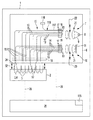
本発明は、付随する図面に関して以下に詳細に記載され、同一の符号は同一または同様のエレメントを示す。まず、図1〜図10を参照すると、液体試料を自動熱処理する例示的な機器の実施形態が説明され、この機器は通常参照符号1として参照される。図1は、図2〜図10で示される例示的な機器の、様々なモジュールを示す。とりわけ図2〜図9は第1の例示的な機器1に言及し、図10は第2の例示的な機器1に言及する。第2の例示的な機器1は、励起装置および検出装置のみ第1の例示的な機器1と異なっている。いくつかの実施形態において機器1は、核酸と1つまたはそれ以上の試薬との反応混合物を、一連の温度逸脱を通して熱循環させ、得られる反応生成物を光学検出するサーマルサイクラーとして構成される。いくつかの実施形態において機器1は、PCR、とりわけリアルタイムPCR、または他のあらゆる核酸増幅型の反応を行うために用いられ得る。いくつかの実施形態において機器1は、反応生成物の光学的なオンライン検出のために用いられ得る。いくつかの実施形態において機器1は、恒温処理または融解曲線の実行のために用いられ得る。
The present invention is described in detail below with reference to the accompanying drawings, wherein like reference numerals indicate like or similar elements. Referring first to FIGS. 1-10, an exemplary instrument embodiment for automatically heat treating a liquid sample is described, which instrument is generally referred to as
とりわけ図1を参照すると、いくつかの実施形態において機器1は、以下の記載において詳述される様々なモジュールを含み、これらモジュールは、液体試料を処理するための機能的または(任意には)構造的な構成要素(entity)である。とりわけいくつかの実施形態において機器1は、液体試料5を受け取るための複数のキャビティーまたはウェル4を備えるマルチウェルプレート3との熱伝達をもたらされ得る熱モジュール2を含む。いくつかの実施形態においてこの熱モジュール2は、制御された方法で熱を試料5にまたは試料5から伝達するよう、予め定められた温度プロファイルにしたがって加熱または冷却され得る。
With particular reference to FIG. 1, in some embodiments, the
引き続き、図1を参照すると、いくつかの実施形態においては試料5のポリメラーゼ連鎖反応の結果として得られ得る反応生成物を特定するために、いくつかの実施形態において、光を検出するために検出モジュール6を用いることができる。いくつかの実施形態において機器1は、増幅反応の進行中に、反応生成物の光学的なオンライン検出に用いることができる。
With continued reference to FIG. 1, in some embodiments, detection is performed to detect light in order to identify reaction products that may be obtained as a result of the polymerase chain reaction of
双方向の矢印により示されるように、いくつかの実施形態において検出モジュール6は、移動機構52(図1では詳述されていない)によって、制御された方法で熱モジュール2に対して少なくとも垂直に動かすことができる。いくつかの実施形態においてこの移動機構52は、自動移動機構である。移動機構52は例えば、駆動式のラック・ピニオン機構または少なくとも検出モジュール6の垂直移動を可能にする他のあらゆる機構として構成することができる。とりわけ移動機構52は例えば、これに限定されるわけではないが、検出モジュール6を自動的に移動させる電気モーターまたは油圧アクチュエータなどの、(制御可能な)ドライバである。当業者であればこのような移動機構の具体的な構成は承知しているので、ここでさらに説明する必要はない。移動機構52を用いて、いくつかの実施形態においては、検出モジュール6は選択的に、試料5から得られる反応生成物を光学的に検出するよう適合された下方の第1位置または動作位置に動かされるか、またはマルチウェルプレート3に対して機器1を装着または離脱するよう適合された、上方の第2位置または非動作位置または装着/離脱位置へと動かされ得る。
As indicated by the double arrows, in some embodiments the
引き続き、図1を参照すると、いくつかの実施形態において検出モジュール6は、励起光9を発生させる少なくとも1つの光源8を備える励起装置7を含み、この励起光9は、試料5による、以下「放射光」と称される光24(例えば蛍光)の放射を励起するよう適合される。図示されるように、いくつかの実施形態において検出モジュール6はさらに、放射光24を光学的に検出する少なくとも1つの検出器11を備える検出装置10を含む。またいくつかの実施形態において検出モジュール6はさらに、概して参照符号12で表される結合装置を含み、この装置は励起装置7および検出装置10のそれぞれをウェル4に光学的に結合するためのものである。より詳細に記載すると、いくつかの実施形態においてこの結合装置12は、以下「励起ファイバー」として示される、励起装置7からの励起光9をウェル4に伝達する複数の第1の光ファイバー13と、以下「放射ファイバー」として示される、ウェル4からの放射光24を検出装置10に伝達する複数の第2の光ファイバー14とを含む。いくつかの実施形態においてマルチウェルプレート3の各ウェル4は、1つの励起ファイバー13と1つの放射ファイバー14という単一のペアと関連づけられる。
With continued reference to FIG. 1, in some embodiments, the
さらに図1に示されているように、いくつかの実施形態では、励起ファイバー13のウェル側の第1の端部15は、第1の固定エレメント16によって互いに対して固定されており、励起ファイバー13の第1の端部15と逆側の第2の端部17は、第2の固定エレメント18によって互いに対して固定されている。またいくつかの実施形態では、放射ファイバー14のウェル側の第1の端部15は第1の固定エレメント16によって互いに固定されており、放射ファイバー14の第1の端部15と逆側の第2の端部17は、第3の固定エレメント19によって固定されている。とりわけ、いくつかの実施形態において励起光9は、第2の端面61において励起ファイバー13に結合され、第1の端面60において励起ファイバー13から切り離され得る。またいくつかの実施形態では、放射光24は、第1の端面60において放射ファイバー14に結合され、第2の端面61において放射ファイバー14から切り離され得る。
As further shown in FIG. 1, in some embodiments, the
さらに図1を参照すると、いくつかの実施形態において、概して参照符号20で表される励起光学系は、第2の端面61で励起光9を励起ファイバー13に光学的に結合するために用いられる。とりわけいくつかの実施形態において、励起光9が励起ファイバー13に結合される前に、1つまたはそれ以上の特定の波長または1つまたはそれ以上の波長帯をフィルターするために、1つまたはそれ以上の励起フィルター22が用いられる。またいくつかの実施形態では、検出モジュール6が動作可能な位置にある場合に、励起ファイバー13の第1の端面60は、励起光9がウェル4に向けられ、試料5による放射光24を励起するように配置される。
Still referring to FIG. 1, in some embodiments, an excitation optics, generally designated by the
さらに図1を参照すると、いくつかの実施形態において、検出モジュール6が動作可能な位置にある場合に、放射ファイバー14の第1の端面60は、放射光24が放射ファイバー14に結合され得るように配置される。いくつかの実施形態において、概して参照符号21で表される放射光学系は、第2の端面61において放射ファイバー14から放たれた放射光24を検出器11に光学的に結合するために用いられる。いくつかの実施形態においては、放射光24が検出器11に達する前に放射光24から1つまたはそれ以上の波長または1つまたはそれ以上の波長帯をフィルターするために、1つまたはそれ以上の放射フィルター23が用いられる。
Still referring to FIG. 1, in some embodiments, the
機器1において、いくつかの実施形態では、一組の光ファイバー13、14が、基準測定を行う光学基準チャネルとして用いられる。通常の試料の代わりに、1つの基準試料または基準試料のセットが、光ファイバー13、14と関連するウェル4に収容される。いくつかの実施形態において基準試料は、蛍光ガラスまたは蛍光クリスタルで作製され、これらに限定されるわけではないがテルビウムガラスまたはルビーで作製される。
In the
さらに図1を参照すると、いくつかの実施形態において機器1は、組み込まれた(専用の)基準チャネル116を有し、これは励起光9を発する光源8の輝度および強度をモニターするよう構成される。基準チャネル116の信号は、光源8を調査するため、および/または例えばフィードバック制御ループによって、励起光9が一定の強度を有するように励起光9の強度を制御するために用いられ得る。代替的には、この基準チャネル116の信号は、測定される試料の蛍光データを正規化(normalize)するために用いられ得る。この基準チャネル116は、光源8によって発生させられた光を、基準チャネルファイバー117を通して伝達される光の強度を測定する基準チャネル検出器118に向けるよう構成される1つの基準チャネルファイバー117からなる。いくつかの実施形態においてこの基準チャネル検出器118は、電子増幅器(図示せず)およびアナログ・デジタルコンバータ(図示せず)に接続されている。
Still referring to FIG. 1, in some embodiments, the
いくつかの実施形態において、試料5の自動熱処理を制御する制御装置25は、マイクロコントローラとして構成され、これは予め定められた工程のシーケンスに従って動作を行うための指令を備えた、コンピュータ読み取り可能なプログラムを実行する。とりわけ、制御装置25は、機器1の様々な構成要素、とりわけ検出器11からの情報を受け取り、対応する制御信号を発生させ、検出モジュール6を垂直に移動させる移動機構52、光源8および熱モジュール2などの、制御を必要とする構成要素にその制御信号を伝達する。図1に概略的に示されるように、いくつかの実施形態においては、電気信号を伝達するために送電線26が用いられる。
In some embodiments, the
とりわけ図2〜図10を参照すると、図1で概略的に示された機器1の例示的な実施形態が説明される。とりわけ、図2〜図9は、例示的な機器1の第1の変形例に言及し、図10は例示的な機器1の第2の変形例に言及する。したがって、いくつかの実施形態において熱モジュール2は、金属材料などの熱伝導率が良好な材料で作製された、温度が制御された(熱)ブロック27を含む。図5に示されるように、いくつかの実施形態において熱ブロック27は熱電素子55を備え、この熱電素子55はいくつかの実施形態においてペルティエ効果を利用する。DC電源(図示せず)に接続されると、各熱電素子55は加えられる電流の向きによって熱を生成または吸収するヒートポンプとして機能する。いくつかの代替的な実施形態では、熱電素子55は、空気で熱ブロック27を冷却するファンなどの冷却手段と組み合わされて、オーム加熱に基づいて加熱され得る抵抗加熱器などの他の加熱装置に置き換えられる。またいくつかの代替的な実施形態において、熱ブロック27は異なる温度を有する液体が流入できるチャネルを備える。通常、先行技術から公知である他の加熱/冷却手段が用いられてもよい。
With particular reference to FIGS. 2 to 10, an exemplary embodiment of the
いくつかの実施形態において熱ブロック27は、その上側でプレート状のレセプタクル28と一体化して形成される。このレセプタクル28は、熱ブロック27と熱伝達するマルチウェルプレート3を保持するように適合され、またいくつかの実施形態においては、ウェル4に収容される試料5への熱伝達/試料5からの熱伝達を可能にするために良好な熱伝導率を有する物質により作製される。いくつかの実施形態において熱モジュール2は、その下側に、熱ブロック27と熱的に結合される熱交換器29を含む。とりわけいくつかの実施形態において、熱交換器29は複数のプレート状のリブ30を備え、これらリブは周囲への効果的な熱伝達を可能にするために、短い相互距離を保って連続的に配置されている。
In some embodiments, the
いくつかの実施形態において、所定の時間の間、試料5の様々な温度に変更および維持するようにレセプタクル28を加熱または冷却するために、熱モジュール2の熱電素子55は、制御装置25による制御の下で、電流を供給され得る。とりわけいくつかの実施形態において制御装置25は、レセプタクル28の温度を所望の温度に調整するために熱電素子55に制御信号を送ることができ、いくつかの実施形態においてこの所望の温度はレセプタクル28および/または試料5の温度を感知するための温度センサ(図示せず)の入力に応じて変わる。
In some embodiments, the
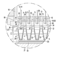
図5に示されるように、いくつかの実施形態において、以下「レセプタクル上面」として記されるレセプタクル28の上面32は複数の凹部33を備え、マルチウェルプレート3が、ウェル4が凹部33の内部にある位置でレセプタクル上に配置され得るように、凹部の内側の輪郭は、少なくともその下部においてウェル4の輪郭と形状が一致する。したがって、少なくとも部分的な締りばめ(close fit)により、レセプタクル28とウェル4との間の良好な熱伝達が得られ、結果として、レセプタクル28とウェル4との間の、非常に効率的な熱伝達をもたらす。またいくつかの実施形態では、以下「プレート下面」として記されるマルチウェルプレート3の下面36が、レセプタクル28とウェル4との間の熱伝達を向上させるために、ウェル間の領域ではレセプタクル上面から間隔を置かれる。
As shown in FIG. 5, in some embodiments, the
いくつかの実施形態においてマルチウェルプレート3は、以下「プレート上面」として記される上面35を有するメイン基板31を含み、この基板は試料5を受け取るために、長方形のウェル4のアレイを備える。このアレイは例えば、8×12ウェル(96ウェル)、6×10ウェル(60ウェル)、16×24ウェル(384ウェル)を含んでもよいし、または、試料5を熱処理する自動化された機器1に適合できるその他の数および配置でもよい。マルチウェルプレート3の設置面積は例えば、長さがおよそ127mm、幅がおよそ85mmのものでもよいが、当業者であれば、マルチウェルプレート3はここで特定される寸法以外の寸法でも形成され得るということを認識するだろう。いくつかの実施形態においてマルチウェルプレート3はこれらに限定されるわけではないが、ポリプロピレン、ポリスチレンおよびポリエチレンなどのプラスティック材料からなる。いくつかの実施形態においてこのマルチプレート3は、単一の試験のために試料5で充填され、その後処分され得るように、一回きりの使用を意図される。
In some embodiments, the
いくつかの実施形態において透明なシールカバー34は、接着または熱シールによりウェル4間に位置づけられるその平面接触領域71で、プレート上面35に固定される。とりわけ、透明なシールカバー34は、試料5の蒸発を防ぐため、および試料5をクロスコンタミネーションなどの外部からの影響から保護するために、上部が開いたウェル4を気密にシールする。いくつかの実施形態においてこの透明なシールカバー34は、励起光9に照射された際に示す蛍光が少ない透明のフィルムなどの、光学的に透明な材料で作製される。またいくつかの実施形態においてこの透明なシールカバー34は、ポリスチレン、ポリエチレンおよびポリエステルからなる群から選択される1つまたはそれ以上のポリマーにより作製される。またいくつかの実施形態においてこの透明なシールカバー34は、例えばポリプロピレンの一層とポリエステルの一層からなる多層フィルムである。またいくつかの実施形態においてこの透明なシールカバー34は、透明なシールカバー34をプレート上面35に固定するために、1つまたはそれ以上の低公害塗料および/または粘着剤またはホットメルト接着剤などの接着剤を含む。透明なシールカバー34は有利には、得られる反応生成物の光学的なオンライン検出ができるように、例えばポリメラーゼ連鎖反応の進行中に放射光24の光学検出をすることを可能にする。ゆえに透明なシールカバー34は、励起光9をウェル4に伝達させ、また放射光24を1つまたはそれ以上の検出器11に戻すように伝達させる。いくつかの実施形態においてシールカバー34は、試料がウェル4に充填された後、かつマルチウェルプレート3が機器1に装着される前に、マルチウェルプレート3に適用される。
In some embodiments, the
とりわけ図2を参照すると、いくつかの実施形態において結合装置12は、ネジ、ボルトまたは溶接接合などの従来の固定手段により組み立てられる、4枚の、垂直プレート39、上側水平プレート40および2枚の離間された底側水平プレート41を含む高剛性の筐体38を含む。いくつかの実施形態において、励起および放射ファイバー13、14の両方の第1の端部15を固定するための第1の固定エレメント16は、筐体38と一体に形成されるように、底側水平プレート41に固定される長方形のソリッドプレートである。いくつかの実施形態において、励起および放射ファイバー13、14の第2の端部17を固定する第2および第3の固定エレメント18、19は、それぞれ、円筒部56およびディスク状の平面部57を含む。図示されるように、いくつかの実施形態において、円筒部56は、それぞれ上側水平プレート40によって形成される第1および第2の開口部43、44に挿入され、プラグのように固定される。上側水平プレート40に固定され、第2および第3の固定エレメント18、19は筐体38と一体に形成される。
With particular reference to FIG. 2, in some embodiments, the
例えば図5に示されるように、いくつかの実施形態において第1の固定エレメント16は、多数の第1の貫通孔42のアレイを備える。いくつかの実施形態では、第1の貫通孔42の数および配置はウェル4の数および配置と対応しており、この場合、この第1の貫通孔42は例えば、ウェル4の真上に配置され得る。さらに図5を参照すると、いくつかの実施形態では、それぞれの第1の貫通孔42が、一対の励起ファイバー13と放射ファイバー14の組の第1の端部15を収容し、励起ファイバー13により伝達された励起光9を、試料5を照射するためにウェル4へ向ける。また、放射光24は放射ファイバー14により受け取られ得る。また代替的ないくつかの実施形態において、2つの第1の貫通孔42が各ウェル4用に備えられ、一方の貫通孔42は励起ファイバー13の第1の端部15を収容するためのものであり、他方の貫通孔42は放射ファイバー14の第1の端部15を収容するためのものである。これにより、各端部15は、別々の第1の貫通孔42に収容される。いくつかの実施形態において、この1つのウェル4に関連する2つの第1の貫通孔42は、0.1〜2mmの範囲で互いに距離を有するように離間される。当業者であれば、ユーザの特定の要望に応じて、ここで特定される相互距離以外の距離も考えられ得ることを認識するだろう。
For example, as shown in FIG. 5, in some embodiments, the first securing
とりわけ、第2または第3の固定エレメント18、19の1つを示す図8を参照すると、いくつかの実施形態において、第2の固定エレメント18は1つの第2の貫通孔45を備え、第3の固定エレメント19は1つの第3の貫通孔46を備え、ここで第2の貫通孔45は励起ファイバー13の第2の端部17を全て収容し、第3の貫通孔46は放射ファイバー14の第2の端部17をすべて収容する。とりわけ、図8は第2の固定エレメント18を示すものの、第3の固定エレメント19に関して括弧内の参照符号によって示されているように、第3の固定エレメント19の構造も同様のものである。図示されるように、いくつかの実施形態において、複数の励起ファイバー13、複数の放射ファイバー14はそれぞれ、互いに対して対応する貫通孔45、46に接着剤63によって固定されており、不規則に配置されてもよい。いくつかの代替的な実施形態において、励起ファイバー13の第2の端部17を収容する1つの第2の貫通孔45および放射ファイバー14の第2の端部17を収容する1つの第3の貫通孔46の代わりに、第2および第3の固定エレメント18、19はそれぞれ、励起および放射ファイバー13、14両方の全ての第2の端部17を収容する1つの貫通孔(図示せず)を備えられ得る。この場合、いくつかの実施形態において、励起および放射ファイバー13、14両方の第2の端部は、接着剤により互いに固定される。また、いくつかのさらに代替的な実施形態においては、励起ファイバー13の第2の端部17を収容する1つの第2の貫通孔45および放射ファイバー14の第2の端部17を収容する1つの第3の貫通孔46の代わりに、第2および第3の固定エレメント18、19はそれぞれ、多数の第1および第2の貫通孔45、46を備えられ得る。より詳細に記載すると、第2の固定エレメント18は、励起ファイバー13の第2の端部17を収容する多数の第2の貫通孔45を備え、ここで各第2の貫通孔45は、励起ファイバー13の第2の端部17を収容する。また、第3の固定エレメント19は、放射ファイバー14の第2の端部17を収容する多数の第3の貫通孔46を備え、ここで各第3の貫通孔46は、放射ファイバー14の第2の端部17を収容する。したがって結合装置12では、個々の光ファイバー13、14について、固定された第1の端部15の第1の端面60と固定された第2の端部17の第2の端面61との間に、一定の1対1の関係またはマッピングが存在する。また、ウェル4と光ファイバー13、14との間で光を伝達させる、検出モジュール6の動作可能な位置において、ウェル4とファイバー13、14の第2の端面61との間に1対1の関係またはマッピングがもたらされる。マッピングにより、励起光9を励起ファイバー13の特定の第2の端面61に結合させ、また放射光24を放射ファイバー14の特定の第2の端面61から切り離すことによって、光は選択的にウェル4のそれぞれに伝達され、および/または選択的にウェル4のそれぞれから受け取られ得る。
In particular, referring to FIG. 8, which shows one of the second or third securing
機器1の拡大詳細図を示す図5および図6に示されるように、いくつかの実施形態では、第1の固定エレメント16は、マルチウェルプレート3に向かって突出する円筒状の突起58を備えるプレート状の平面部72を備える。とりわけいくつかの実施形態では、第1の貫通孔42のそれぞれが平面部72を貫通し、中央の位置で1つの突起58を収容する。より詳細に記載すると、いくつかの実施形態において1つの第1の貫通孔42は、一対の励起ファイバー13と放射ファイバー14の組の第1の端部15を収容し、ここで第1の端面60は、第1の貫通孔42の円形の開口部59と同一平面上にある。さらに、いくつかの実施形態において第1の貫通孔42のそれぞれは、接着剤63で充填される第1の固定エレメント16の上側に隣接する、環状の幅の広いくぼみ62を備えられ、これは収容される光ファイバー13、14の第1の端部15を固定するためである。図5では、1つの第1の貫通孔42につき1つの光ファイバー13、14が示されているが、いくつかの実施形態では、図6に示されるように各第1の貫通孔42が、1つの励起ファイバー13および1つの放射ファイバー14を収容することを理解されたい。同様に、光ファイバー13、14の第2の端部17は、接着剤によって第2および第3の固定エレメント18、19にそれぞれ固定され、接着剤については図面ではさらに詳細には示さない。したがって、光ファイバー13、14は、固定された第1および第2の端部15、17以外の領域では固定されない。いくつかの代替的な実施形態(図示せず)では、光ファイバー13、14の運動性を減少させるために、光ファイバー13、14は例えば、これに限定されるわけではないが、ウレタンフォームなどの接着剤によって第1および第2の端部15、17の間でも固定される。
As shown in FIGS. 5 and 6, which show enlarged detailed views of the
光ファイバー13、14の少なくとも1つの第1および第2の端部15、17は互いに対して固定されるという事実により、検出モジュール6の垂直方向への移動の間に機械的な力が光ファイバー13、14に作用することは回避され得る。したがって、通常光ファイバー13、14の光学的特性の望ましくない変化を伴う、光ファイバー13、14の形状の変化(ファイバーのたわみ)が、有利に回避され得る。ゆえに検出結果の信頼性および再現性が向上する。また、光ファイバー13、14の寿命も延ばされ得る。
Due to the fact that at least one first and second ends 15, 17 of the
図6に示されるように、いくつかの実施形態において、励起ファイバー13および放射ファイバー14のそれぞれは、これらに限定されるわけではないが石英ガラスまたはプラスティックポリマーなどの光学的に透明な材料で作製されるコア76からなる。いくつかの実施形態においてこのコア76は、コア76中の光を維持するよう、コア76よりも低い光屈折率を有する材料で作製される被覆材(図示せず)により被覆される。図示されるようにいくつかの実施形態では、ファイバー13、14を容易に通すことができるように不透明な被覆77を備えられ、機器1の製造を容易にするこの被覆77は取り除かれない。いくつかの実施形態では、コア76は0.05mm〜1.5mm、好ましくは0.1mm〜0.8mmの範囲にある直径を有する。またいくつかの実施形態では、被覆77を含む光ファイバー13、14は、0.3mm〜2mm、好ましくは0.4mm〜1.0mmの範囲にある直径を有する。
As shown in FIG. 6, in some embodiments, each of the
とりわけPCRを行う場合、試料5は、熱サイクル工程の間中、合理的に可能な限り単一な温度を有することが望ましく、これは小さな変化でも増幅工程の失敗または望ましくない結果を引き起こし得るからである。また、ウェル4は通常完全には試料5で充填されないので、ウェル4には、液体試料5とシールカバー34との間に空隙が存在し得る。ゆえに、熱サイクルはシールカバー34の裏面において凝縮物の形成を引き起こすおそれがあり、これはシールカバー34の光伝達を低下させるので放射光24の光学検出に干渉するおそれがある。またそうでなくても凝縮物は、反応混合物の組成を変化させる可能性がある。
Especially when performing PCR, it is desirable for
さらに図5および図6を参照すると、上述のような欠点を克服するためにいくつかの実施形態では、結合装置12は底側水平プレート41と良好な熱接触にあるような方法で、筐体38の底側水平プレート41に固定されるシールカバー34を加熱するカバーヒーター64を含む。とりわけいくつかの実施形態では、カバーヒーター64は、金属材料、例えばステンレス鋼またはアルミニウムなど良好な熱伝導率を有する物質で作製される加熱プレート66を含む。この加熱プレート66は、検出モジュール6の動作可能な位置でシールカバー34に接触する底側接触面37を有する。いくつかの実施形態では、加熱プレート66は2mm〜7mmの範囲にある厚さを有する。いくつかの実施形態では、加熱プレート66は5W/m/Kよりも大きな熱伝導率を有する。
Still referring to FIGS. 5 and 6, in some embodiments to overcome the disadvantages described above, in some embodiments, the
図示されるようにいくつかの実施形態では、このカバーヒーター64はさらに、加熱プレート66のプレート上面69に加えられる熱を発生させる加熱エレメント65を含む。いくつかの実施形態では、加熱エレメント65はオーム加熱を発生させるよう適合され、例えば、抵抗加熱線(図示せず)を備えられ得る。
As shown, in some embodiments, the cover heater 64 further includes a
さらに図5を参照すると、いくつかの実施形態では、加熱プレート66は複数のプレートホール67を備え、その数および配置はマルチウェルプレート3のウェル4に対応する。図示されるようにいくつかの実施形態では、検出モジュール6の動作可能な位置において、接触面37は隣接するウェル4の間の接触領域71でのみシールカバー34に接触する。とりわけいくつかの実施形態では、ウェル4をレセプタクル28の凹部33に押し込んで、マルチウェルプレート3と熱ブロック27との間で確実な熱接触を得るために、接触面37を用いて接触領域71に機械的な力が加えられ得る。一般にカバーヒーター64は、とりわけウェル4の外側と内側で温度差を引き起こすおそれのあるエッジ効果を減少させることによって、試料5の中での温度の誤差および変化を最小限にできる。また、シールカバー34上への凝縮物の形成は有利に回避され得る。
With further reference to FIG. 5, in some embodiments, the
いくつかの実施形態において制御装置25は、所望の熱出力を調整するために、送電線(図示せず)によってカバーヒーター64に電気的に接続され、この所望の熱出力は、いくつかの実施形態では加熱プレート66の温度を感知する1つまたはそれ以上の温度センサー(図示せず)からの入力に応じて変更される。いくつかの実施形態では、加熱プレート66の温度が反応混合物の最大温度よりも5℃から15℃高いような方法で熱出力を調整することが好ましく、この温度は、ポリメラーゼ連鎖反応の場合には例えば95℃から110℃の範囲にある。
In some embodiments, the
さらに図5および図6を参照すると、いくつかの実施形態では、加熱エレメント65は複数のエレメントホール70を備え、このホールはそれぞれプレートホール67中に開口しているので、共通のカバーヒーターホール78を形成する。図6に示されるように、いくつかの実施形態では、エレメントホール70はプレートホール67と同一平面上にある。いくつかの実施形態では、カバーヒーターホール78は、円筒状の貫通孔として構成される。いくつかの実施形態では、光ファイバー13、14を収容する突起58のそれぞれは、伝導熱が光ファイバー13、14に伝達するのを回避するために、カバーヒーター64と直接接触せずに別々のヒーターホール78に入り込む。
With further reference to FIGS. 5 and 6, in some embodiments, the
いくつかの実施形態では、検出モジュール6の動作可能な状態、すなわちウェル4の間で接触面37が接触領域71に接触する位置において、カバーヒーターホール78は、試料5の温度の均一性を向上させるために、有利には対流空気を回避する閉鎖されたキャビティーを形成する。またいくつかの実施形態では、空気が入った複数のキャビティー68が、第1の固定エレメント16の平面部72の平面部下面73と、加熱エレメント65のエレメント上面74との間に形成される。したがって、第1の固定エレメント16、とりわけそこに固定される光ファイバー13、14と、カバーヒーター64との間の熱伝達が減少され得る。
In some embodiments, the
いくつかの実施形態では、カバーヒーターホール78および/またはカバーヒーター64の上のキャビティー68が、光ファイバー13、14とカバーヒーター64との間の熱的結合を減少させるために、プラスティック材料などの熱伝導率が低い物質で少なくとも部分的に充填される。いくつかの実施形態では、光ファイバー13、14は、プラスティック材料などの熱伝導率が低い物質で被覆されるか、またはこの物質に埋め込まれ、これは光ファイバー13、14とカバーヒーター64との間の熱的結合を減少させ、また検出モジュール6を作動させる際の、物質のわずかな歪曲をも防ぐためである。いくつかの実施形態において熱伝導率が低い物質は、光ファイバー13、14を第1の貫通孔42内に固定するために用いられる。
In some embodiments, the
材料によっては、光ファイバー13、14の固定、および時には光ファイバー13、14自体が、熱に対して敏感である。光ファイバー13、14は、上述したように大部分がカバーヒーター64から熱的に切り離されているという事実から、光ファイバー13、14およびその固定の寿命は有利に延ばされ得る。同様に、カバーヒーター64からの、励起および放射光学系20、21の熱的な切り離しもまた達成され得る。別の利点は、ウェル4が互いに光学的に遮蔽されるように、各ウェル4が、1つのカバーホール78のみと光学的につながるという事実によりもたらされる。
Depending on the material, the fixation of the
さらに図2および図3を参照すると、いくつかの実施形態では、励起装置7は第1のケーシング47に収容され、このケーシングは以下「水平プレート上面75」として記される上側の水平プレート40の上面に固定されており、筐体38と一体に形成される。励起装置7の目的は、励起光を励起ファイバー13に向けることである。当業者であれば、波長、電力、一様性および開口は、ユーザの特定の要望にしたがって選択されるデザインに左右されるということを理解するだろう。
Still referring to FIGS. 2 and 3, in some embodiments, the
図2に示されるように、いくつかの実施形態において励起装置7は、これらに限定されるわけではないが、2種類の異なる波長を有する発光ダイオード(LED)などの、2つの光源8を含む。この光源8は互いに直交関係で配置され、各光源8は、ダイクロイックミラー48で入射する励起光9をフィルターする1つまたはそれ以上の励起フィルター22に結合される。いくつかの実施形態において光学系は例えば、光を励起ファイバー13に向けるために、8mmの直径および0.15の開口数を有する均一な照射点を作り出すように設計される。いくつかの実施形態では、2つまたはそれ以上のLEDが、ダイクロイックミラー、および/またはファイバー光学系、および/または移動または回転するミラーまたはプリズムなどの移動または回転エレメントによって結合され、これは光を励起アダプターに向けるためである。多色LEDの使用は、高い励起電力に有利である。様々な励起波長帯で蛍光を測定するために、LEDはスイッチで切り替えられてもよいし、回転エレメントが回転されてもよい。いくつかの実施形態では、ハロゲンランプなどの白光源または白LEDが、(図1に示されるように)フィルターホイールまたはフィルタースラッジと組み合わせて用いられる。いくつかの実施形態では、検出装置10は、筐体38と一体に形成される水平プレート上面75に固定されている第2のケーシング49に収容される。検出装置10の目的は放射ファイバー14から出る放射光24を測定することである。
As shown in FIG. 2, in some embodiments, the
図示されるようにいくつかの実施形態では、検出装置10は複数の検出器11を含み、放射光24を光学的に検出するために、各検出器11が1つの感光素子を有するか、または少なくとも1つの検出器11が複数の感光素子を有する。感光素子は、これらに限定されるわけではないが、電荷結合素子(CCD)およびCMOS素子などの横方向分解検出器、走査のために動かされ得るリニアアレイ検出器およびカメラセンサーなどの二次元配列センサーである。放射光学系21は放射光24を検出器11に向けて伝達するために用いられ、この検出器11はいくつかの実施形態では、放射光24をフィルターする複数の放射フィルター23の1つに光学的に結合される。
As shown, in some embodiments, the
さらに図2を参照すると、いくつかの実施形態では、複数の放射フィルター23は、1つの放射フィルター23を放射光24の光路に選択的に移動させるように、電気モーター51によって中央回転軸の周りを回転させられ得るフィルターホイール50に取り付けられる。いくつかの実施形態において放射光24は、例えば、ダイクロイックミラーおよび/または従来のフィルターによって色分離された後に、CCDカメラなどの複数の検出器に同時に向けられる。より詳細に記載すると、いくつかの実施形態では、放射ファイバー14の第2の端部17の第2の端面61の画像は、第2の端面61と検出器11のピクセルとの間の1対1マッピングを有することなく、検出器11によって得られる。その代わりにこの画像は、各ファイバーからの光強度を決定するために処理される。放射ファイバー14の第1および第2の端部15、17の1対1マッピングの情報に基づき、決定された光強度が特定の容器によるものとされる。いくつかの代替的な実施形態では、各第2の端面61が1つの割り当てられた検出器11に関連付けられるように、複数の検出器11が1対1の関係で放射ファイバー14の第2の端面に割り当てられ得る。
Still referring to FIG. 2, in some embodiments, a plurality of radiating
いくつかの実施形態において励起および放射光学系20、21は、励起光9を試料5に伝達させ、複数の検出器11によって放射光24を検出するために、これらに限定されるわけではないがレンズおよび平面ミラーまたは湾曲ミラーなどの、1つまたはそれ以上の導光エレメントおよび/または光成形エレメントおよび/または光配向エレメント(図示せず)、および/または、これらに限定されるわけではないが、透過回折格子、反射回折格子およびプリズムなどの分光エレメント(図示せず)を含む。このため、いくつかの実施形態では、制御装置25が、励起光9を放射し、かつ放射光24を検出する制御信号を出力するために、光源8および検出器11に光学的に結合される。また、励起および放射フィルター22、23はユーザの特定の要望にしたがって変更され得る。
In some embodiments, the excitation and
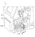
とりわけ図7Aおよび図7Bを参照すると、いくつかの実施形態では、機器1は、検出モジュール6が熱モジュール2に対して少なくとも垂直に動かされることを可能にする自動移動機構52を含む。いくつかの実施形態では、検出モジュール6は垂直および水平に動かされ得る。図示されるように、いくつかの実施形態において移動機構52は、検出モジュール6を直線上に案内するために、筐体38の2枚の底側水平プレート41に案内係合され熱ブロック27に固定される2つの垂直な案内レール53を含む。いくつかの実施形態においてこの移動機構52はさらに、検出モジュール6を熱モジュール2に対して、案内レール53に沿って移動させるために、これらに限定されるわけではないが、筐体38に光学的に結合されるスピンドルドライブなどの作動機構を含む。ゆえに、検出モジュール6は、熱モジュール2に向かうよう、また熱モジュール2から離れるように、少なくとも垂直に動かされ得る。図7Aに示されるようにいくつかの実施形態において、検出モジュール6は試料5を熱処理するために動作可能な位置まで垂直に下降され、また図7Bに示されるように、検出モジュール6が熱モジュール2から離される動作不能な位置まで垂直に上昇され得る。とりわけ動作不能な位置において、自由空間54が検出モジュール6と熱モジュール2との間に形成され、この空間は試料5を熱処理するためにマルチプレートウェル3を熱ブロック27上の位置に持ち込むことを可能にする。いくつかの実施形態では、マルチウェルプレート3は手動で熱ブロック27上に配置され、またそこから取り除かれ得る。当業者であれば、自由空間54の垂直方向の寸法はユーザの特定の要望にしたがって変更され得るということを認識するだろう。
With particular reference to FIGS. 7A and 7B, in some embodiments, the
一方いくつかの実施形態において移動機構52は、熱モジュール2に検出モジュール6を強制的に押圧するように、すなわちマルチウェルプレート3に所望の圧力を加えるように適合される。これによりウェル4は、マルチウェルプレート3と熱ブロック27との間の熱伝達を向上させ、熱分配を均一にする目的で、接触面37を用いてレセプタクル28の凹部33に圧入され得る。また、この圧力は、透明なカバー34の封止効果を向上し得る。いくつかの実施形態において検出モジュール6は、手動でマルチプレート3上に押圧され得る。またいくつかの実施形態において検出モジュール6は、自動的にマルチプレート3上に押圧され得る。このために、いくつかの実施形態において制御装置25は、制御信号を出力して自動化された検出モジュール6の垂直動作を調整するために、移動機構52に電気的に接続される。いくつかの実施形態では、マルチウェルプレート3に加えられる圧力は100N〜1000Nの範囲、好ましくは200N〜600Nの範囲である。また、いくつかの実施形態において検出モジュール6は、機器1を手動および/または自動でマルチウェルプレート3に取り付け、またそこから取り外すために自由空間54を形成する動作不能な位置に手動で上昇され得る。
On the other hand, in some embodiments, the moving
とりわけ図9A〜9Fを参照すると、いくつかの実施形態では、熱モジュール2は、マルチウェルプレート3をレセプタクル28に取り付けるため、またそこから取り除くために、それぞれ、機器ケーシング90外部の取り付けおよび/または取り外し位置に運び出される。また熱モジュール2は、液体試料5を熱処理するためおよび検出装置10によって得られる反応生成物を検出するために、機器ケーシング90内部の処理位置に運び込まれ得る。より詳細に記載すると、機器1は水平移動可能なトレイ102を含み、このトレイ102は、熱モジュールを支持する水平な支持ベース103と、熱モジュール2の処理位置において機器ケーシング90を閉鎖するために支持ベース103に取り付けられる垂直な正面カバー105とを含む。この支持ベース103は、機器1の基板89に垂直に固定される水平な案内レール113に、摺動自在に係合される1つまたは2つの平行なはり104を含み、トレイ102を、機器ケーシング90の内部へまたは外部に摺動可能に移動させ得る。
With particular reference to FIGS. 9A-9F, in some embodiments, the
機器1は概して参照符号108で表される双安定型の開放/閉鎖装置を含み、これはトレイ102の開放または閉鎖動作を自動的に行い、トレイ102を閉鎖位置で固定するためのものである。とりわけ、この双安定型の開放/閉鎖装置108は、回転ナックル97から放射状に突出する第1アーム98および第2アーム99を中央軸109の周りで回転自在に支持する中央回転ナックル97を含む。回転ナックル97は、支持ベース103の案内レール113に対して平行に配置されている水平な案内ロッド100によって摺動可能に支持される。2つのアーム98、99はその自由端部で、コイルスプリング101によって相互接続される。トレイ102は、支持基板103に固定される弾性変形可能なスプリングキャッチ107によって、開放/閉鎖装置108に解放可能なように接続される。とりわけスプリングキャッチ107は、回転ナックル97とともに移動可能なように、開放/閉鎖装置108に固定される突起112と係合する、深くなったレスト部114を形成する。機器1はさらに、支点92で機器1に固定されるレバー91を含む。支点92の片側では、レバー91が上側のレバー部分93を有し、このレバー部分93はその上端95で、接続ロッド96によって垂直に移動可能な検出モジュール6に結合される。また支点92の反対側では、レバー91が下側のレバー部分94を有し、このレバー部分94はその下端110で、水平に移動可能な回転ナックル97に結合される。
The
とりわけ図9Aを参照すると、熱モジュール2が、試料5を熱処理するために機器ケーシング90の内部の処理位置にある状態が示される。この状態において検出モジュール6は、放射光24を検出するために、例えばマルチウェルプレート3に圧力を加えるような、下側の動作可能な位置にある。双安定型の開放/閉鎖装置108の2つのアームは、回転ナックル97の片側(例えば図9Aでは左側)で第1の安定位置にあり、ここでその自由端部はコイルスプリング101に弾性的に接続される。この第1の安定位置において、2つのアーム98、99は約90度の角度を形成し、この角度はアーム98、99の回転動作を停止するためのストッパー(図示せず)により容易に到達され得る。この状態においてトレイ102は、スプリングキャッチ107のレスト部114に載る突起112に係合されたスプリングキャッチ107によって開放/閉鎖装置108に接続される。したがって、トレイ102が開放されるべき場合にはコイルスプリング101の弾性力を克服しなければならないので、トレイ102は、不注意による手動の開放から守られる。
With particular reference to FIG. 9A, the
とりわけ図9Bおよび図9Cを参照すると、他の状態が2つの斜視図で示され、ここで検出モジュール6は、垂直な移動機構52によって垂直に上昇された動作不能な位置に持ちこまれている。動作不能な位置において検出モジュール6は熱モジュール2から離間され、これはその間に自由空間54を作り出すためである。検出モジュール6を垂直方向に移動させる場合、回転ナックル97が、回転ナックル97に結合される下側のレバー部分94によって案内ロッド100に沿って(例えば、左側に)動かされるように、レバー91が支点92において回転される(例えば図9Bおよび図9Cでは、時計回りの方向に)。トレイ102は突起112に結合され、正面カバー105の上側によって形成される、トレイ102を手動で把持するための凹状把持部106が外側からアクセス可能になるように、水平方向(図9Bおよび図9Cでは左側)に同時に動かされる。また、検出モジュール6を上昇させる場合には、2つのアーム98、99は不安定な位置を越えて回転され、不安定な位置とは、これらアームがコイルスプリング101を弾性的に拡張するような、反対方向に延伸する位置である。
With particular reference to FIGS. 9B and 9C, another situation is shown in two perspective views, in which the
とりわけ図9Dおよび図9Eを参照すると、2つのアーム98、99は収縮するコイルスプリング101の弾性力によって駆動され、回転ナックル97の反対側(例えば図9Dおよび図9Eでは、右側)の第2の安定位置に持ち込まれる。この第2の安定位置において、アーム98、99の自由端はコイルスプリング101によって弾性的に接続され、このコイルスプリング101はここでも、アームの回転動作を停止するためのストッパー(図示せず)により容易に到達され得る約90度の角度を形成する。結果として、スプリングキャッチ107により開放/閉鎖装置108に結合されるトレイ102は、凹状把持部106が外側から完全にアクセスできる位置において動かされる。
With particular reference to FIGS. 9D and 9E, the two
とりわけ図9Fを参照すると、凹状把持部106を手動で把持することにより、トレイ102は、機器ケーシング90から引き出され、マルチウェルプレート3を熱モジュール2のレセプタクル28に取り付け、またそこから取り外すための、取り付け/取り外し位置に持ち込まれる。トレイ102を取り付け/取り外し位置において手動で移動させる場合、スプリングキャッチ107はその弾性力を弱めることにより突起112との係合から取り外され、トレイ102は双方向型の開放/閉鎖装置108から解放される。
With particular reference to FIG. 9F, by manually grasping the concave
また、支持ベース103は逆動作によって機器ケーシング90に容易に送り返され得る。したがってトレイ102は、スプリングキャッチ107が突起112と係合するまで、凹状把持部106で機器ケーシング90に手動で圧入される。さらにトレイ102は、2つのアーム98、99が反対方向に延伸してコイルスプリング101を弾性的に拡張するような不安定な位置を越えて回転されるまで、案内ロッド100に沿って回転ナックル97を移動させるように内側に向かって(例えば、右側に向かって)圧入される。ここで2つのアーム98、99は収縮するコイルスプリング101の弾性力によって駆動され、第1の安定位置に持ち込まれ、この位置ではトレイ102が、正面カバー105が機器ケーシング90を閉鎖する閉鎖位置に自動的に移動され、また熱モジュール2は処理位置にある。
Further, the support base 103 can be easily sent back to the
いくつかの実施形態では、ウェル4は機器1に装着される前にあらかじめ試料5を充填される。いくつかの実施形態においてウェル4は、マルチウェルプレート3がレセプタクル28に位置づけられる時に試料5を充填される。またいくつかの実施形態では、試料5は様々な温度逸脱を受けるので、そこに収容される反応混合物を所定の培養間隔の間所定の温度で培養し、これは例えば、ポリメラーゼ連鎖反応を行うためである。試料5の温度は例えば、核酸を融解するためにおよそ90℃まで上昇されてもよく、プライマーのアニーリングおよび変性ポリヌクレオチドのストランドに沿ったプライマーの伸長のために約40℃〜70℃に降下されてもよい。いくつかの実施形態において核酸の融解は、例えば試料5の温度がゆっくりと上昇または下降される間に試料5の蛍光が検出されるような状態で行われる。一般的な融解曲線は30℃〜50℃で開始し、75℃〜95℃で終了してもよく、この場合例えば、0.05〜0.25℃/secの範囲のランプ速度が用いられ得る。
In some embodiments, the
試料5の自動的な温度循環のための機器1は非常に小型に作製されてもよく、これは短い光ファイバー13、14の使用を可能にする。光ファイバー13、14の固定された第1の端部15の第1の端面60は、放射光24の光学検出の感度を向上させる一方でファイバー13、14とシールカバー34との間の一切の直接的な接触を回避するように、透明なシールカバー34に非常に近接させられる。いくつかの実施形態では、第1の端面60と透明なシールカバー34との間の(垂直)距離は、0.5mm〜5mmの範囲であり、好ましくは1mm〜3mmの範囲である。
The
いくつかの実施形態では、機器1は放射光24のリアルタイム(オンライン)検出を行うように作動され、これは例えば、熱処理の進行中であっても全ての試料5に対して同時にその反応生成物を特定するためである。とりわけいくつかの実施形態では、試料5は、全ての試料5に対して並行して放射光24を同時に検出しながら、熱サイクルされ得る。いくつかの実施形態では、一対の光ファイバー13、14により、励起光9の励起ファイバー13への結合および放射光24の放射ファイバー14からの分離が、全ての試料5に対して同時に、かつ並行して行われ得る。
In some embodiments, the
別の例示的な機器1を示す図10に示されるように、いくつかの実施形態では、励起および検出装置7、10の両方が、垂直な光路を有するように配置され、ここで励起装置7は励起光9をフィルターするために1つまたはそれ以上の励起フィルター22に光学的に結合される1つの光源8のみを含む。したがって試料5を照射するための、図2に示されるようなダイクロイックミラーを用いる必要がない。
As shown in FIG. 10, which shows another
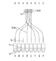
次に、機器1の光ファイバー13、14の第1の端部15と第2の端部17との間の1対1の関係を測定するための例示的な方法を示す、図11および図12を参照する。とりわけ図11を参照すると、いくつかの実施形態において光ファイバー13、14の第1の端部15は第1の固定エレメント16(図11には図示せず)によって互いに固定され、一方で励起ファイバー13の第2の端部17は第2の固定エレメント18によって互いに固定され、放射ファイバー14の第2の端部17は第3の固定エレメント19によって互いに固定される。図11では、図示の目的のためだけに一種の光ファイバー13、14が示されているが、図11は同様に、励起ファイバー13および放射ファイバー14の両方に適用できることを理解されたい。
Next, an exemplary method for measuring the one-to-one relationship between the
いくつかの実施形態では、第1〜第3の固定エレメント16、18、19のそれぞれにおいて、光ファイバー13、14の第1および第2の端部15、17の確率的(stochastic)またはランダムな配置があり、これはそれらの製造を相当に容易にする。これは、製造中に特定の配列(scheme)または順番(ordering)を監視する必要がないからである。ゆえに、検出モジュール6の動作可能な位置において、第1の端部15とウェル4との間の1対1の関係を確立する位置にあり、例えばウェル4の真上に位置づけられる光ファイバー13、14の第1の端部15に関して、励起ファイバー13の第1の端部15を出る励起光9がどのウェル4に向けられているのかは最初は明らかではない。また、より重要なことには、どの試料5によって放射ファイバー14の特定の第2の端部17を出る放射光24が発生しているのかが最初は明らかではない。例えばA、B、C、D、E、F、GおよびHとして記される、連続して配置される8つのウェル4の放射光24は、放射ファイバー14の連続して配列される第2の端部17、すなわちG、F、A、D、H、B、EおよびCによって検出され得る。ゆえに、放射ファイバー14の第1の端部15と第2の端部17との間での、試料5の正確なマッピング(1対1の関係)を知らずには、試料5は個別に(選択的に)検出され得ない。このような欠点を克服するために、各光ファイバー13、14の、第1および第2の端部15、17間でのマッピングが決定されなければならない。
In some embodiments, stochastic or random placement of the first and second ends 15, 17 of the
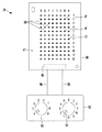
とりわけ図12を参照すると、いくつかの実施形態では、各光ファイバー13、14の、第1および第2の端部15、17間のマッピングを決定する装置79(以下「マッピング装置」と記す)が用いられる。図示されるようにいくつかの実施形態では、これに限定されるわけではないがダイオードなどの複数の光発生エレメント81の長方形アレイを備える基板上面87を有する平面なプレート状の基板80を含む。いくつかの実施形態では、光発生エレメント81の数および配置は、マルチウェルプレート3のウェル4と対応する。いくつかの実施形態では、光発生エレメント81は、互いに直角に交差する複数の並行な縦列および複数の並行な横列で配置される。図示されるようにいくつかの実施形態においてマッピング装置は例えば、機器1に用いられるマルチウェルプレート3によって、8つの縦列および12の横列1〜12の光発生エレメント81を含む。
With particular reference to FIG. 12, in some embodiments, an apparatus 79 (hereinafter “mapping apparatus”) that determines the mapping between the first and second ends 15, 17 of each
さらに図12を参照すると、いくつかの実施形態では、マッピング装置79はさらにコントロールパネル82を含み、これは2つの手動で動作可能な切り替えスイッチ83、84を備える。とりわけいくつかの実施形態では、第1の切り替えスイッチ83は特定の縦列A〜Hを設定するために用いられ、第2の切り替えスイッチ84は特定の横列1〜12を設定するために用いられ得る。いくつかの実施形態では、コントロールパネル82は装置の制御装置85に接続されており、この制御装置85は、送電線86によって光発生エレメント81を制御するために、基板80の裏側に固定される。切り替えスイッチ83、84による設定にしたがって、光発生エレメント81は光を発生させるために、選択的に電流を供給され得る。
Still referring to FIG. 12, in some embodiments, the
さらに図12を参照すると、いくつかの実施形態において基板80は、検出モジュール6が動作可能な状態で動かされ得るように、マルチウェルプレート3の代わりにレセプタクル28上に配置されるよう構成される。いくつかの実施形態では、放射ファイバー14の第1の端部15が、各第1の端部15が別々の光発生エレメント81に関連づけられるように、光発生エレメント81の真上に配置される。いくつかの実施形態では、加熱プレート66の底側接触面37は光発生エレメント81との間の接触領域88において基板上面87と接触し、これは各光発生エレメント81が個別のカバーヒーターホルダー78に収容されるようにするためである。したがっていくつかの実施形態では、接触面37が基板上面87に接触する場合には、光発生エレメント81は互いに対して光学的に遮断される。
Still referring to FIG. 12, in some embodiments, the
したがって、縦列および横列によってもたらされる光発生エレメント81それぞれの正確な位置を知ることにより、いくつかの実施形態では、光発生エレメント81は光を発生するよう連続的に電流を供給され、この光は放射ファイバー14の第1の端部15に結合され、その第2の端部17で結合が解かれる。したがって、光発生エレメント81の光を検出する検出器11によって、放射ファイバー14の第1の端部15またはウェル4と、第2の端部17との間の1対1の関係(マッピング)が容易に確立され得る。いくつかの実施形態においてこの1対1の関係は、ウェル4またはそこに収容される試料5が選択的に検出されるように、例えばルックアップテーブルの形状で、例えば永久データ記憶装置115に保存される。
Thus, by knowing the exact position of each of the
上に詳述されるように、いくつかの実施形態では、放射ファイバー14の第2の端部17の第2の端面61の画像は、第2の端面61と検出器11の画像との間の1対1のマッピングを有することなく、検出器11によって得られる。また、放射ファイバー14の第1および第2の端部15、17間での、公知の1対1の関係(マッピング)に基づく電子画像処理を用いることができ、これは検出された光を個別のウェル4に帰するよう、検出器11の画像と、放射ファイバー14の第2の端面61の画像との関係について情報を得るためである。
As detailed above, in some embodiments, the image of the
とりわけ図13〜図15を参照すると、図2〜図10の機器1のレセプタクル28をクランプするクランプ機構129が記載される。実際問題としていくつかの実施形態では、これに限定されるわけではないが機器1を熱循環器として用いる場合、レセプタクル28は適切な範囲で可能な限り一定な温度分散を有することを要求される。この要求に適うために、レセプタクル28は、熱ブロック27の1つまたはそれ以上の熱電素子55にクランプされる。クランプ機構129は、ウェルにより定められた圧力および圧力分散をレセプタクル28に加えるように構成される。より詳細に記載すると、いくつかの実施形態においてクランプ機構129は、これに限定されるわけではないがDIN規格1.4310によるスプリング鋼などの、弾性材料で作製される弾性クランプ123を含む。いくつかの実施形態ではこのクランプ123は、フラットスプリングとして構成される。とりわけ図示されるように、いくつかの実施形態においてクランプ123は中央部分127によって接続される2つの対向するアーム126を有する延長部材として構成される。この中央部分127は、レセプタクル28の基板プレート125で静止するアイソレーション・ブロック124を備えられる。アイソレーション・ブロック124は、これに限定されるわけではないが繊維強化ポリマーなどの、熱遮蔽材料で作製される。クランプ123の両側のフランジ119は、アーム126の把持部分128と把持係合する把持凹部130を備えられる。フランジ119は、ネジ120によって熱ブロック27に動かないように固定され、このネジ120は取り付け穴121にねじ込まれ、またそこから巻き上げられ得る。したがって、ネジ120をねじ込むことにより、アーム126の把持部分128はアーム126を歪曲しながら基板プレート125に向かって移動され得る。結果として、クランプ力が中央部分127を通して基板プレート125に加えられ、これによりレセプタクル28を1つまたはそれ以上の熱電素子55にクランプするので、機械負荷が均等になる。図示されるように、いくつかの実施形態では、クランプ力のさらなる均一化により、これらに限定されるわけではないが熱伝達のために適合されるオイル、ペーストまたはホイルなどの、良好な熱伝導性を有する材料により作製される熱電素子55の片面または両面にある1つまたはそれ以上の界面層122により温度分配が達成され得る。熱アイソレーション・ブロック124は、レセプタクル28から熱ブロック27への過度な熱流を、クランプ123を用いて妨げ、例えば、レセプタクル28が例えば95℃の温度まで加熱される場合には、熱ブロック27はより低い温度、例えば35℃の温度を有する。いくつかの実施形態では、例えば、約16cm2の面積を有する熱電素子55のために、クランプ123は200N〜500Nの範囲でクランプ力を加えるように構成される。当業者であれば、しかしながら、レセプタクル28に加えられるクランプ力はユーザの特定の要望にしたがって変更されてもよく、いくつかの実施形態では10N〜1000Nの範囲である場合もあることを理解するだろう。いくつかの実施形態ではクランプ機構129の代わりに、機器1はレセプタクル28を熱電素子55にクランプする複数のクランプ機構129を含む。
With particular reference to FIGS. 13-15, a
言うまでもなく、上記の記載に鑑みて、本発明の多数の修正および変更が可能である。それゆえ添付の請求項の範囲内で、本発明は詳細に考案されたもの以外に実行されてもよいということを理解されたい。いくつか例を挙げると、いくつかの実施形態では励起装置7および検出装置10は結合装置12と一体には形成されず、これは軽量の結合装置12が、励起装置7および検出装置10を動かさずに、試料5を処理するための動作位置またはマルチウェルプレート3を取り付け/取り外しするための非動作位置へと垂直に移動されることを可能にする。この場合、ファイバー13、14の第2の端面61が励起装置7および検出装置10に光学的に結合されていることが要求される。またいくつかの実施形態では、構成上の高さを減少できるように、検出モジュール6が熱モジュール2に対して横に配置される。またいくつかの実施形態では、ウェル4に対して1組の光ファイバー13、14を用いる代わりに、1つの光ファイバーのみが、励起光および放射光の両方を伝達するために用いられる。この場合、励起光および放射光はダイクロイックミラーを用いて光学的に切り離され得る。またいくつかの実施形態では、励起光9および放射光24を伝達するために、1つのウェル4に対して光ファイバー13、14の束が用いられる。またいくつかの実施形態では、第1の貫通孔42はウェル4に対して垂直に配置される代わりに、ウェル4の(例えば水平な)開放面に対して傾けられる。またいくつかの実施形態では、各励起ファイバー13および放射ファイバー14の組が2つの貫通孔に収容されるように、一組の光ファイバー13、14を1つの貫通孔42、45、46に収容する代わりに、各ファイバー13、14が別個の貫通孔に収容される。この場合、1組の光ファイバー13、14の貫通孔は例えば、0.2mmといった最小限の間隔を有していればよい。なお、上記の変更された実施形態は網羅的なものではない。
Obviously, many modifications and variations of the present invention are possible in light of the above description. It is therefore to be understood that within the scope of the appended claims, the invention may be practiced other than as specifically designed. In some examples, in some embodiments, the
1 機器
2 熱モジュール
3 マルチウェルプレート
4 ウェル
5 試料
6 検出モジュール
7 励起装置
8 光源
9 励起光
10 検出装置
11 検出器
12 結合装置
13 励起ファイバー
14 放射ファイバー
15 第1の端部
16 第1の固定エレメント
17 第2の端部
18 第2の固定エレメント
19 第3の固定エレメント
20 励起光学系
21 放射光学系
22 励起フィルター
23 放射フィルター
24 放射光
25 制御装置
26 送電線
27 熱ブロック
28 レセプタクル
29 熱交換器
30 リブ
31 メイン基板
32 レセプタクル上面
33 凹部
34 シールカバー
35 プレート上面
36 プレート下面
37 接触面
38 筐体
39 垂直プレート
40 上側水平プレート
41 底側水平プレート
42 第1の貫通孔
43 第1の開口部
44 第2の開口部
45 第2の貫通孔
46 第3の貫通孔
47 第1のケーシング
48 ダイクロイックミラー
49 第2のケーシング
50 フィルターホイール
51 電気モーター
52 移動機構
53 レール
54 自由空間
55 熱電素子
56 円筒部
57 ディスク状の平面部
58 突起
59 開口部
60 第1の端面
61 第2の端面
62 くぼみ
63 接着剤
64 カバーヒーター
65 加熱エレメント
66 加熱プレート
67 プレートホール
68 キャビティー
69 プレート上面
70 エレメントホール
71 接触領域
72 平面部
73 平面部下面
74 加熱エレメント上面
75 水平プレート上面
76 コア
77 被覆
78 カバーヒーターホール
79 マッピング装置
80 基板
81 光発生エレメント
82 コントロールパネル
83 第1の切り替えスイッチ
84 第2の切り替えスイッチ
85 装置の制御装置
86 送電線
87 基板上面
88 接触領域
89 基板
90 機器ケーシング
91 レバー
92 支点
93 上側のレバー部分
94 下側のレバー部分
95 上端
96 接続ロッド
97 回転ナックル
98 第1のアーム
99 第2のアーム
100 案内ロッド
101 コイルスプリング
102 トレイ
103 支持ベース
104 はり
105 正面カバー
106 凹状把持部
107 スプリングキャッチ
108 開放/閉鎖装置
109 中央軸
110 下端
112 突起
113 案内レール
114 レスト部
115 データ記憶装置
116 基準チャネル
117 基準チャネルファイバー
118 基準チャネル検出器
119 フランジ
120 ネジ
121 取り付け穴
122 界面層
123 クランプ
124 アイソレーション・ブロック
125 基板プレート
126 アーム
127 中間部分
128 把持部分
129 クランプ機構
130 把持凹部
DESCRIPTION OF SYMBOLS 1 Apparatus 2 Thermal module 3 Multiwell plate 4 Well 5 Sample 6 Detection module 7 Excitation apparatus 8 Light source 9 Excitation light 10 Detection apparatus 11 Detector 12 Coupling apparatus 13 Excitation fiber 14 Radiation fiber 15 1st edge part 16 1st fixation Element 17 Second end 18 Second fixed element 19 Third fixed element 20 Excitation optical system 21 Radiation optical system 22 Excitation filter 23 Radiation filter 24 Radiation light 25 Controller 26 Transmission line 27 Heat block 28 Receptacle 29 Heat exchange Container 30 Rib 31 Main board 32 Receptacle upper surface 33 Recess 34 Seal cover 35 Plate upper surface 36 Plate lower surface 37 Contact surface 38 Housing 39 Vertical plate 40 Upper horizontal plate 41 Bottom horizontal plate 42 First through hole 43 First opening 4 Second opening 45 Second through hole 46 Third through hole 47 First casing 48 Dichroic mirror 49 Second casing 50 Filter wheel 51 Electric motor 52 Moving mechanism 53 Rail 54 Free space 55 Thermoelectric element 56 Cylinder Part 57 disk-shaped flat part 58 projection 59 opening 60 first end face 61 second end face 62 depression 63 adhesive 64 cover heater 65 heating element 66 heating plate 67 plate hole 68 cavity 69 plate upper surface 70 element hole 71 contact Area 72 Plane portion 73 Plane portion bottom surface 74 Heating element top surface 75 Horizontal plate top surface 76 Core 77 Covering 78 Cover heater hole 79 Mapping device 80 Substrate 81 Light generating element 82 Control panel 83 First cut Changeover switch 84 Second changeover switch 85 Device control device 86 Transmission line 87 Upper surface of substrate 88 Contact area 89 Substrate 90 Equipment casing 91 Lever 92 Support point 93 Upper lever portion 94 Lower lever portion 95 Upper end 96 Connecting rod 97 Rotary knuckle 98 First arm 99 Second arm 100 Guide rod 101 Coil spring 102 Tray 103 Support base 104 Beam 105 Front cover 106 Concave grip 107 Spring catch 108 Opening / closing device 109 Central shaft 110 Lower end 112 Protrusion 113 Guide rail 114 Rest Part 115 Data storage device 116 Reference channel 117 Reference channel fiber 118 Reference channel detector 119 Flange 120 Screw 121 Mounting hole 122 Interface layer 123 Clamp 124 Isolation block 125 Substrate plate 126 Arm 127 Intermediate part 128 Holding part 129 Clamp mechanism 130 Holding recess
Claims (15)
前記液体試料(5)を収容する複数の容器(4)を装着するための温度制御されたレセプタクル(28)であって、前記装着された容器(4)と熱伝達を形成するように構成されるレセプタクル(28)と、
試料(5)から放射される放射光(24)を検出する1または2以上の検出器(11)を備える検出装置(10)と、前記放射光(9、24)を前記検出装置(10)へ伝達する複数の光ファイバー(13、14)を備える結合装置(12)とを備える検出モジュール(6)であって、前記光ファイバー(13、14)は第1の端部および第2の端部(15、17)を有し、各光ファイバー(13、14)の前記第1の端部(15)および前記第2の端部(17)が互いに対して固定されている検出モジュール(6)と、
前記容器(4)が前記レセプタクル(28)に装着されること、または前記レセプタクル(28)から離脱されることを可能にし、かつ前記レセプタクル(28)に装着された1または2以上の容器(4)に収容される試料(5)からの光(24)の検出を可能にするために、前記結合装置(12)と前記レセプタクル(28)との間の相互距離を変更する方法で、前記結合装置および/または前記レセプタクル(28)を移動させる移動機構(52)と
を含んでなる機器(1)。 An apparatus (1) for automatically heat-treating a liquid sample (5),
A temperature controlled receptacle (28) for mounting a plurality of containers (4) containing the liquid sample (5), wherein the receptacle (28) is configured to form heat transfer with the mounted containers (4). A receptacle (28),
A detection device (10) including one or more detectors (11) for detecting radiation (24) emitted from the sample (5), and the radiation (9, 24) to the detection device (10). A detection module (6) comprising a coupling device (12) comprising a plurality of optical fibers (13, 14) for transmitting to the optical fiber (13, 14), the first end and the second end ( A detection module (6) having a first end (15) and a second end (17) of each optical fiber (13, 14) fixed relative to each other;
One or more containers (4) that allow the container (4) to be attached to or detached from the receptacle (28) and attached to the receptacle (28) In order to allow detection of light (24) from the sample (5) contained in the), the coupling device (12) and the receptacle (28) are modified in a manner that alters the mutual distance between the coupling (12) and the receptacle (28). A device (1) comprising an apparatus and / or a moving mechanism (52) for moving the receptacle (28).
前記液体試料(5)を収容する複数の容器(4)を装着する温度制御されたレセプタクル(28)と光ファイバー(13、14)の端部(15)との間の相互距離を変更する工程を含んでなり、
前記レセプタクル(28)は前記装着された容器(4)と熱伝達を形成するように構成され、前記光ファイバー(13、14)は第1および第2の端部(15、17)を有し、光(9、24)を伝達するために各光ファイバー(13、14)の前記第1の端部(15)および前記第2の端部(17)が互いに対して固定され、前記相互距離の変更が、前記容器(4)が前記レセプタクル(28)に装着され、または前記レセプタクルから離脱されることを可能にし、かつレセプタクル(28)に装着された1または2以上の容器(4)に収容される試料(5)からの光(24)の検出を可能にする方法。 A method of automatically heat-treating a liquid sample (5),
Changing the mutual distance between the temperature-controlled receptacle (28) for mounting the plurality of containers (4) containing the liquid sample (5) and the ends (15) of the optical fibers (13, 14); Comprising
The receptacle (28) is configured to form heat transfer with the mounted container (4), the optical fiber (13, 14) having first and second ends (15, 17); The first end (15) and the second end (17) of each optical fiber (13, 14) are fixed with respect to each other to transmit light (9, 24), and the mutual distance change Is accommodated in one or more containers (4) that allow the container (4) to be attached to or detached from the receptacle (28) and attached to the receptacle (28). Enabling detection of light (24) from the sample (5).
Applications Claiming Priority (2)
| Application Number | Priority Date | Filing Date | Title |
|---|---|---|---|
| EP10191156.8 | 2010-11-15 | ||
| EP10191156.8A EP2463661B1 (en) | 2010-11-15 | 2010-11-15 | Instrument and method for the automated thermal treatment of liquid samples |
Publications (2)
| Publication Number | Publication Date |
|---|---|
| JP2012108129A true JP2012108129A (en) | 2012-06-07 |
| JP5872856B2 JP5872856B2 (en) | 2016-03-01 |
Family
ID=43798475
Family Applications (1)
| Application Number | Title | Priority Date | Filing Date |
|---|---|---|---|
| JP2011248919A Active JP5872856B2 (en) | 2010-11-15 | 2011-11-14 | Apparatus and method for automatic heat treatment of liquid samples |
Country Status (6)
| Country | Link |
|---|---|
| US (3) | US8797526B2 (en) |
| EP (3) | EP2463661B1 (en) |
| JP (1) | JP5872856B2 (en) |
| CN (1) | CN102533539B (en) |
| CA (1) | CA2757783C (en) |
| HK (1) | HK1168621A1 (en) |
Cited By (8)
| Publication number | Priority date | Publication date | Assignee | Title |
|---|---|---|---|---|
| WO2014014016A1 (en) * | 2012-07-17 | 2014-01-23 | ユニバーサル・バイオ・リサーチ株式会社 | Light measurement apparatus for reaction vessel, and light measurement method |
| JP2016524124A (en) * | 2013-03-15 | 2016-08-12 | ハイコア バイオメディカル インコーポレイテッド | Apparatus and related methods for performing luminescence and fluorescence measurements of samples |
| JP2017090112A (en) * | 2015-11-05 | 2017-05-25 | ウシオ電機株式会社 | Optical measurement device |
| KR20170138993A (en) * | 2015-02-06 | 2017-12-18 | 라이프 테크놀로지스 코포레이션 | Biological analysis system and method |
| JP2020060572A (en) * | 2013-01-04 | 2020-04-16 | メソ スケール テクノロジーズ エルエルシー | Analysis evaluation device, method, and reagent |
| JP2020187139A (en) * | 2013-03-14 | 2020-11-19 | ジェン−プローブ・インコーポレーテッド | Apparatus for detecting signal emission from a plurality of fluorescent sources |
| JP2021171045A (en) * | 2020-04-17 | 2021-11-01 | コネクタクセン カンパニー リミテッド | Portable isothermal amplification detector |
| JP2021536572A (en) * | 2018-08-31 | 2021-12-27 | ルシッド サイエンティフィック, インク.Lucid Scientific, Inc. | Dynamic system measurement |
Families Citing this family (38)
| Publication number | Priority date | Publication date | Assignee | Title |
|---|---|---|---|---|
| EP2463661B1 (en) | 2010-11-15 | 2014-01-08 | F. Hoffmann-La Roche AG | Instrument and method for the automated thermal treatment of liquid samples |
| WO2013133725A1 (en) | 2012-03-09 | 2013-09-12 | Rawle Christopher Bruce | Portable device for detecting molecule(s) |
| US20140211204A1 (en) * | 2012-08-31 | 2014-07-31 | Board Of Trustees Of Michigan State University | Hand-held wireless platform and optics for measurement of dna, rna, micrornas, and other markers of pathogens, genetic diseases, and cancer |
| FR2999288B1 (en) * | 2012-12-11 | 2016-01-08 | Envolure | MICROPLATE READER DEVICE |
| DE102013101176B4 (en) * | 2013-02-06 | 2018-04-05 | Cybio Ag | Cooling box with a rack equipped with tube-shaped vessels for automatic filling with a pipetting machine |
| WO2014137228A1 (en) * | 2013-03-08 | 2014-09-12 | Otago Innovation Limited | Reaction vessel holder and molecule detection device |
| WO2014179483A2 (en) * | 2013-05-02 | 2014-11-06 | Bio-Rad Laboratories, Inc. | Drawer handle mechanism |
| GB2526520B (en) * | 2014-04-04 | 2021-08-18 | It Is Int Ltd | Biochemical reaction system |
| CN107076770B (en) | 2014-07-28 | 2019-07-12 | 道格拉斯科学有限责任公司 | For analyzing the instrument of biological sample and reagent |
| DE102014115564A1 (en) * | 2014-10-27 | 2016-04-28 | Christian-Albrechts-Universität Zu Kiel | Mobile photometric measuring device and method for the mobile photometric measurement of microtiter plates |
| GB2531616B (en) * | 2015-02-02 | 2017-11-22 | Atlas Genetics Ltd | Instrument for performing a diagnostic test on a fluidic cartridge |
| CA2987397C (en) * | 2015-05-29 | 2022-03-01 | Illumina, Inc. | Sample carrier and assay system for conducting designated reactions |
| EP3311163B1 (en) | 2015-06-19 | 2020-08-05 | The Regents of the University of California | Micro-plate reader for elisa testing |
| RU2640186C2 (en) * | 2015-11-19 | 2017-12-26 | Федеральное государственное бюджетное учреждение науки Институт аналитического приборостроения Российской академии наук (ИАП РАН) | Device for real time simultaneous control of plurality of nucleic acid amplifications |
| US11213827B2 (en) * | 2015-12-09 | 2022-01-04 | Indian Institute of Technology Guwahati | Device with integrated methods for reverse transcription polymerase chain reaction (RT-PCR) and/or DNA/protein array based analyses |
| US10161872B2 (en) * | 2016-04-14 | 2018-12-25 | Shimadzu Corporation | Optical measuring device and safety device used therein |
| RU2666209C2 (en) * | 2016-09-22 | 2018-09-06 | Федеральное государственное бюджетное учреждение науки Институт аналитического приборостроения Российской академии наук (ИАП РАН) | Apparatus for real-time simultaneous monitoring of multiple nucleic acid amplifications |
| JP6849405B2 (en) * | 2016-11-14 | 2021-03-24 | 浜松ホトニクス株式会社 | Spectral measuring device and spectroscopic measuring system |
| WO2018102346A1 (en) * | 2016-11-29 | 2018-06-07 | The Regents Of The University Of California | Antimicrobial susceptibility testing device and method for use with portable electronic devices |
| KR102423452B1 (en) * | 2017-09-19 | 2022-07-20 | 제네리치 바이오테크놀로지 코포레이션 | Heating apparatus of biochemical reaction device |
| US10260033B1 (en) * | 2017-10-06 | 2019-04-16 | Wyatt Technology Corporation | Method and apparatus to mitigate evaporation in high throughput measurements |
| EP3721211A4 (en) * | 2017-12-06 | 2021-08-18 | California Institute of Technology | System for analyzing a test sample and method therefor |
| CN108031140B (en) * | 2018-01-22 | 2023-07-28 | 上海仪乐智能仪器有限公司 | Full-automatic batch reflux condensing device |
| SG10201801853WA (en) * | 2018-03-02 | 2019-10-30 | Delta Electronics Int’L Singapore Pte Ltd | Portable multi-color fluorescence detection device |
| WO2019231339A1 (en) * | 2018-06-01 | 2019-12-05 | Ubiquitome Limited | Heater for apparatus for detecting molecule(s) |
| DE102018212489A1 (en) * | 2018-07-26 | 2020-01-30 | Implen GmbH | Device for light spectroscopic analysis |
| EP3614128B1 (en) | 2018-08-22 | 2023-04-26 | F. Hoffmann-La Roche AG | A method to correct signal light intensities measured by a detector of a detection unit in a laboratory instrument |
| CN109283139B (en) * | 2018-10-25 | 2023-12-01 | 湖南正中制药机械有限公司 | Lamp inspection machine large disc tracking device |
| CN110426240B (en) * | 2019-06-17 | 2022-02-11 | 浙江省海洋水产研究所 | Device and method for taking out underwater sludge and attachments |
| GB2601501A (en) | 2020-12-01 | 2022-06-08 | Stratec Se | Optical fiber coupling in a real-time thermal cycler |
| CN112816649B (en) * | 2021-01-04 | 2023-03-10 | 郎溪县重振钢构有限公司 | Head and tail detection device for steel bar production |
| CN112857856B (en) * | 2021-01-20 | 2021-09-03 | 东北农业大学 | Animal manure sample acquisition and storage device |
| CN113046230B (en) * | 2021-03-17 | 2024-02-27 | 杭州博日科技股份有限公司 | PCR instrument, detection method of PCR instrument and electronic terminal |
| CN113466071B (en) * | 2021-05-28 | 2023-01-24 | 昆明华城兴建材有限公司 | Hardness detection device of cement board |
| CN113621482A (en) * | 2021-08-11 | 2021-11-09 | 林曙晓 | Food fermentation device |
| CN114563352B (en) * | 2022-04-27 | 2022-07-19 | 深圳市标谱半导体科技有限公司 | Light source installation component and braid detection device |
| US20240110874A1 (en) * | 2022-09-30 | 2024-04-04 | Endress+Hauser Optical Analysis, Inc. | Intensity calibration of multipass raman systems using standard reference materials |
| CN116297416B (en) * | 2023-05-22 | 2023-11-10 | 科美诊断技术股份有限公司 | Photo-excitation chemiluminescence detection device and detection method |
Citations (6)
| Publication number | Priority date | Publication date | Assignee | Title |
|---|---|---|---|---|
| JPH11500232A (en) * | 1995-12-05 | 1999-01-06 | ザ パーキン−エルマー コーポレイション | Optical cuvette |
| US20030175813A1 (en) * | 1998-11-12 | 2003-09-18 | 3-Dimensional Pharmaceuticals, Inc. | Microplate thermal shift assay for ligand development using 5- (4"-dimethylaminophenyl) -2- (4' -phenyl) oxazole derivative fluorescent dyes |
| JP2008059867A (en) * | 2006-08-30 | 2008-03-13 | Seiko Epson Corp | Organic electroluminescent device, its manufacturing method, and electronic apparatus |
| JP2008519266A (en) * | 2004-11-04 | 2008-06-05 | アプレラ コーポレイション | Optical scanning system comprising a thermally compensated light emitting diode |
| WO2010079338A2 (en) * | 2009-01-08 | 2010-07-15 | It-Is International Ltd | Optical system for chemical and/or biochemical reactions |
| WO2011124918A1 (en) * | 2010-04-06 | 2011-10-13 | It-Is International Limited | Biochemical reactions system |
Family Cites Families (40)
| Publication number | Priority date | Publication date | Assignee | Title |
|---|---|---|---|---|
| US3636366A (en) * | 1964-05-08 | 1972-01-18 | Sheldon Edward E | Opto-electric screens provided with light-conducting members |
| DE3340006A1 (en) | 1983-11-04 | 1985-05-23 | Hans Rudolf Prof. Dipl.-Chem. Dr. 8000 München Pfaendler | METHOD FOR PRODUCING AZETIDIN-2-ONES |
| US4683195A (en) | 1986-01-30 | 1987-07-28 | Cetus Corporation | Process for amplifying, detecting, and/or-cloning nucleic acid sequences |
| US4965188A (en) | 1986-08-22 | 1990-10-23 | Cetus Corporation | Process for amplifying, detecting, and/or cloning nucleic acid sequences using a thermostable enzyme |
| US4800159A (en) | 1986-02-07 | 1989-01-24 | Cetus Corporation | Process for amplifying, detecting, and/or cloning nucleic acid sequences |
| AU585033B2 (en) * | 1986-07-04 | 1989-06-08 | Tosoh Corporation | Quantitative dispenser for a liquid |
| JPS63298137A (en) | 1987-05-29 | 1988-12-05 | Soken:Kk | Sample analyzer using image fiber |
| US5994056A (en) | 1991-05-02 | 1999-11-30 | Roche Molecular Systems, Inc. | Homogeneous methods for nucleic acid amplification and detection |
| US5670113A (en) | 1991-12-20 | 1997-09-23 | Sibia Neurosciences, Inc. | Automated analysis equipment and assay method for detecting cell surface protein and/or cytoplasmic receptor function using same |
| JPH0634546A (en) | 1992-07-17 | 1994-02-08 | Tosoh Corp | Fluorescene detector |
| CA2159830C (en) | 1994-04-29 | 2001-07-03 | Timothy M Woudenberg | System for real time detection of nucleic acid amplification products |
| US5589351A (en) | 1994-12-06 | 1996-12-31 | Nps Pharmaceuticals, Inc. | Fluorescence detection apparatus |
| IT1280954B1 (en) | 1995-10-05 | 1998-02-11 | Sorin Biomedica Cardio Spa | PROCEDURE AND SYSTEM FOR DETECTING CHEMICAL-PHYSICAL PARAMETERS. |
| US6043880A (en) * | 1997-09-15 | 2000-03-28 | Becton Dickinson And Company | Automated optical reader for nucleic acid assays |
| ES2224347T3 (en) | 1998-05-01 | 2005-03-01 | F. Hoffmann-La Roche Ag | APPARATUS TO SIMULTANEOUSLY CONTROL THE REACTIONS THAT HAVE PLACED A PLURALITY OF REACTION CONTAINERS. |
| EP0953838A1 (en) | 1998-05-01 | 1999-11-03 | F. Hoffmann-La Roche Ag | Apparatus for simultaneously monitoring reactions taking place in a plurality of reaction vessels |
| ATE278471T1 (en) * | 1998-05-04 | 2004-10-15 | Hoffmann La Roche | THERMOCYCLING APPARATUS WITH AN AUTOMATICALLY POSITIONABLE LID |
| US6838680B2 (en) | 1999-05-12 | 2005-01-04 | Aclara Biosciences, Inc. | Multiplexed fluorescent detection in microfluidic devices |
| CA2374596A1 (en) | 1999-05-20 | 2000-11-30 | Illumina, Inc. | Method and apparatus for retaining and presenting at least one microsphere array to solutions and/or to optical imaging systems |
| US6657169B2 (en) * | 1999-07-30 | 2003-12-02 | Stratagene | Apparatus for thermally cycling samples of biological material with substantial temperature uniformity |
| JP2002098696A (en) * | 2000-09-26 | 2002-04-05 | Inst Of Physical & Chemical Res | Integrated biomolecule sensor |
| DE10202999B4 (en) * | 2002-01-26 | 2004-04-15 | Palas Gmbh Partikel- Und Lasermesstechnik | Method and device for measuring the size distribution and concentration of particles in a fluid |
| AU2003243281A1 (en) | 2002-05-17 | 2003-12-02 | Applera Corporation | Optical instrument includung excitation source |
| GB0221167D0 (en) | 2002-09-12 | 2002-10-23 | Quanta Biotech Ltd | Control apparatus |
| CN100374579C (en) * | 2003-04-04 | 2008-03-12 | 霍夫曼-拉罗奇有限公司 | Improved system for multicolor real time PCR |
| US7136550B2 (en) | 2004-10-28 | 2006-11-14 | Corning Incorporated | Single-fiber launch/receive system for biosensing applications |
| DE102005043834A1 (en) * | 2005-09-13 | 2007-03-22 | Eppendorf Ag | Device for performing real-time PCR reactions |
| US20070098594A1 (en) | 2005-11-03 | 2007-05-03 | Roche Molecular Systems, Inc. | Analytical multi-spectral optical detection system |
| US7715001B2 (en) | 2006-02-13 | 2010-05-11 | Pacific Biosciences Of California, Inc. | Methods and systems for simultaneous real-time monitoring of optical signals from multiple sources |
| US7872749B2 (en) * | 2006-03-23 | 2011-01-18 | Nanodrop Technologies Llc | Instrument for making optical measurements on multiple samples retained by surface tension |
| DE102006036017B4 (en) | 2006-08-02 | 2008-07-31 | Haldex Brake Products Gmbh | Compressed air supply unit |
| JP2008089321A (en) | 2006-09-29 | 2008-04-17 | Fujifilm Corp | Biosensor detector |
| JP2008122297A (en) * | 2006-11-14 | 2008-05-29 | Fujitsu Ltd | Device and method for detecting fluorescence |
| WO2009027102A2 (en) | 2007-08-29 | 2009-03-05 | Eppendorf Ag | Device and method for radiometric measurement of a plurality of samples |
| EP2276574B1 (en) * | 2008-04-04 | 2019-06-12 | IT-IS International Ltd | Thermal control system and method for chemical and biochemical reactions |
| CN201530828U (en) * | 2009-07-28 | 2010-07-21 | 呼吸疾病国家重点实验室 | Full-automatic serial fluorescent PCR detecting system |
| EP2463643B1 (en) * | 2009-08-06 | 2020-01-15 | Universal Bio Research Co., Ltd. | Optical fiber measurement device and measurement method using same |
| EP2311563A1 (en) * | 2009-08-07 | 2011-04-20 | F. Hoffmann-La Roche AG | Processing units and methods for the processing of liquid samples |
| EP2463661B1 (en) | 2010-11-15 | 2014-01-08 | F. Hoffmann-La Roche AG | Instrument and method for the automated thermal treatment of liquid samples |
| WO2013131017A1 (en) * | 2012-03-02 | 2013-09-06 | Laxco, Inc. | Multichannel analytical instruments for use with specimen holders |
-
2010
- 2010-11-15 EP EP10191156.8A patent/EP2463661B1/en active Active
- 2010-11-15 EP EP13162185.6A patent/EP2615462B1/en active Active
- 2010-11-15 EP EP16199095.7A patent/EP3151015A1/en not_active Withdrawn
-
2011
- 2011-11-14 US US13/295,504 patent/US8797526B2/en active Active
- 2011-11-14 JP JP2011248919A patent/JP5872856B2/en active Active
- 2011-11-14 CA CA2757783A patent/CA2757783C/en active Active
- 2011-11-14 CN CN201110359110.3A patent/CN102533539B/en active Active
-
2012
- 2012-09-25 HK HK12109445.8A patent/HK1168621A1/en unknown
-
2014
- 2014-04-02 US US14/243,524 patent/US9557269B2/en active Active
-
2016
- 2016-12-20 US US15/385,020 patent/US9956559B2/en active Active
Patent Citations (6)
| Publication number | Priority date | Publication date | Assignee | Title |
|---|---|---|---|---|
| JPH11500232A (en) * | 1995-12-05 | 1999-01-06 | ザ パーキン−エルマー コーポレイション | Optical cuvette |
| US20030175813A1 (en) * | 1998-11-12 | 2003-09-18 | 3-Dimensional Pharmaceuticals, Inc. | Microplate thermal shift assay for ligand development using 5- (4"-dimethylaminophenyl) -2- (4' -phenyl) oxazole derivative fluorescent dyes |
| JP2008519266A (en) * | 2004-11-04 | 2008-06-05 | アプレラ コーポレイション | Optical scanning system comprising a thermally compensated light emitting diode |
| JP2008059867A (en) * | 2006-08-30 | 2008-03-13 | Seiko Epson Corp | Organic electroluminescent device, its manufacturing method, and electronic apparatus |
| WO2010079338A2 (en) * | 2009-01-08 | 2010-07-15 | It-Is International Ltd | Optical system for chemical and/or biochemical reactions |
| WO2011124918A1 (en) * | 2010-04-06 | 2011-10-13 | It-Is International Limited | Biochemical reactions system |
Cited By (16)
| Publication number | Priority date | Publication date | Assignee | Title |
|---|---|---|---|---|
| JPWO2014014016A1 (en) * | 2012-07-17 | 2016-07-07 | ユニバーサル・バイオ・リサーチ株式会社 | Photometric device for reaction vessel and method thereof |
| WO2014014016A1 (en) * | 2012-07-17 | 2014-01-23 | ユニバーサル・バイオ・リサーチ株式会社 | Light measurement apparatus for reaction vessel, and light measurement method |
| US11156801B2 (en) | 2013-01-04 | 2021-10-26 | Meso Scale Technologies, Llc. | Assay apparatuses, methods and reagents |
| JP2020060572A (en) * | 2013-01-04 | 2020-04-16 | メソ スケール テクノロジーズ エルエルシー | Analysis evaluation device, method, and reagent |
| US11966086B2 (en) | 2013-03-14 | 2024-04-23 | Gen-Probe Incorporated | Determining temperature-varying signal emissions during automated, random-access thermal cycling processes |
| JP7206022B2 (en) | 2013-03-14 | 2023-01-17 | ジェン-プローブ・インコーポレーテッド | Apparatus for detecting signal emissions from multiple fluorescent sources |
| JP2020187139A (en) * | 2013-03-14 | 2020-11-19 | ジェン−プローブ・インコーポレーテッド | Apparatus for detecting signal emission from a plurality of fluorescent sources |
| JP2020187138A (en) * | 2013-03-14 | 2020-11-19 | ジェン−プローブ・インコーポレーテッド | Apparatus for detecting signal emission from a plurality of fluorescent sources |
| JP2016524124A (en) * | 2013-03-15 | 2016-08-12 | ハイコア バイオメディカル インコーポレイテッド | Apparatus and related methods for performing luminescence and fluorescence measurements of samples |
| KR20170138993A (en) * | 2015-02-06 | 2017-12-18 | 라이프 테크놀로지스 코포레이션 | Biological analysis system and method |
| KR102375707B1 (en) * | 2015-02-06 | 2022-03-18 | 라이프 테크놀로지스 코포레이션 | Biological analysis systems and methods |
| JP2018505680A (en) * | 2015-02-06 | 2018-03-01 | ライフ テクノロジーズ コーポレーション | Systems and methods for biological analysis |
| JP2017090112A (en) * | 2015-11-05 | 2017-05-25 | ウシオ電機株式会社 | Optical measurement device |
| JP2021536572A (en) * | 2018-08-31 | 2021-12-27 | ルシッド サイエンティフィック, インク.Lucid Scientific, Inc. | Dynamic system measurement |
| JP2021171045A (en) * | 2020-04-17 | 2021-11-01 | コネクタクセン カンパニー リミテッド | Portable isothermal amplification detector |
| JP7062847B2 (en) | 2020-04-17 | 2022-05-09 | コネクタゲン インコーポレイテッド | Portable isothermal amplification detector |
Also Published As
| Publication number | Publication date |
|---|---|
| EP2615462A1 (en) | 2013-07-17 |
| CA2757783A1 (en) | 2012-05-15 |
| EP2463661B1 (en) | 2014-01-08 |
| EP3151015A1 (en) | 2017-04-05 |
| JP5872856B2 (en) | 2016-03-01 |
| US20170100715A1 (en) | 2017-04-13 |
| EP2463661A1 (en) | 2012-06-13 |
| CA2757783C (en) | 2019-12-31 |
| CN102533539B (en) | 2015-02-25 |
| US9956559B2 (en) | 2018-05-01 |
| US8797526B2 (en) | 2014-08-05 |
| US20120295249A1 (en) | 2012-11-22 |
| HK1168621A1 (en) | 2013-01-04 |
| US9557269B2 (en) | 2017-01-31 |
| CN102533539A (en) | 2012-07-04 |
| EP2615462B1 (en) | 2016-12-14 |
| US20140220669A1 (en) | 2014-08-07 |
Similar Documents
| Publication | Publication Date | Title |
|---|---|---|
| JP5872856B2 (en) | Apparatus and method for automatic heat treatment of liquid samples | |
| US11966086B2 (en) | Determining temperature-varying signal emissions during automated, random-access thermal cycling processes | |
| EP2419743B1 (en) | OPTICAL DETECTION SYSTEM FOR MONITORING rtPCR REACTION | |
| JP2019198328A (en) | System, method, and apparatus for automated incubation | |
| US20150102025A1 (en) | Heated Cover Methods and Technology | |
| US9644234B2 (en) | Methods and device to balance radiation transference | |
| US20080006202A1 (en) | Compressible transparent sealing for open microplates | |
| CA3009080C (en) | Light-mediated polymerase chain reaction amplification and product detection system and methods of use | |
| JP2003344290A (en) | Fluorescence detector with temperature controller | |
| JP6754420B2 (en) | Convection PCR device | |
| US20040241691A1 (en) | Thermo-optical analysis system for biological reactions | |
| WO2013100859A1 (en) | Methods and device to balance radiation transference | |
| WO2004024330A2 (en) | Thermocycler and sample holder | |
| KR20040048754A (en) | Temperature controlled real time fluorescence detection apparatus | |
| JP2023545555A (en) | Systems and methods for rapid multiplexed sample processing with application to nucleic acid amplification assays | |
| WO2023057338A1 (en) | Integrated system for chemical, biochemical or molecular biological reactions in a microplate |
Legal Events
| Date | Code | Title | Description |
|---|---|---|---|
| A621 | Written request for application examination |
Free format text: JAPANESE INTERMEDIATE CODE: A621 Effective date: 20140723 |
|
| RD02 | Notification of acceptance of power of attorney |
Free format text: JAPANESE INTERMEDIATE CODE: A7422 Effective date: 20140723 |
|
| A977 | Report on retrieval |
Free format text: JAPANESE INTERMEDIATE CODE: A971007 Effective date: 20150326 |
|
| A131 | Notification of reasons for refusal |
Free format text: JAPANESE INTERMEDIATE CODE: A131 Effective date: 20150421 |
|
| A521 | Request for written amendment filed |
Free format text: JAPANESE INTERMEDIATE CODE: A523 Effective date: 20150713 |
|
| TRDD | Decision of grant or rejection written | ||
| A01 | Written decision to grant a patent or to grant a registration (utility model) |
Free format text: JAPANESE INTERMEDIATE CODE: A01 Effective date: 20160105 |
|
| A61 | First payment of annual fees (during grant procedure) |
Free format text: JAPANESE INTERMEDIATE CODE: A61 Effective date: 20160114 |
|
| R150 | Certificate of patent or registration of utility model |
Ref document number: 5872856 Country of ref document: JP Free format text: JAPANESE INTERMEDIATE CODE: R150 |
|
| R250 | Receipt of annual fees |
Free format text: JAPANESE INTERMEDIATE CODE: R250 |
|
| R250 | Receipt of annual fees |
Free format text: JAPANESE INTERMEDIATE CODE: R250 |
|
| R250 | Receipt of annual fees |
Free format text: JAPANESE INTERMEDIATE CODE: R250 |
|
| R250 | Receipt of annual fees |
Free format text: JAPANESE INTERMEDIATE CODE: R250 |
|
| R250 | Receipt of annual fees |
Free format text: JAPANESE INTERMEDIATE CODE: R250 |
|
| R250 | Receipt of annual fees |
Free format text: JAPANESE INTERMEDIATE CODE: R250 |