JP2012104992A - Reproduction device, reproduction method, presentation device, and reproduction system - Google Patents
Reproduction device, reproduction method, presentation device, and reproduction system Download PDFInfo
- Publication number
- JP2012104992A JP2012104992A JP2010250714A JP2010250714A JP2012104992A JP 2012104992 A JP2012104992 A JP 2012104992A JP 2010250714 A JP2010250714 A JP 2010250714A JP 2010250714 A JP2010250714 A JP 2010250714A JP 2012104992 A JP2012104992 A JP 2012104992A
- Authority
- JP
- Japan
- Prior art keywords
- volume
- acoustic data
- unit
- value
- parameter
- Prior art date
- Legal status (The legal status is an assumption and is not a legal conclusion. Google has not performed a legal analysis and makes no representation as to the accuracy of the status listed.)
- Granted
Links
Images


Classifications
-
- H—ELECTRICITY
- H03—ELECTRONIC CIRCUITRY
- H03G—CONTROL OF AMPLIFICATION
- H03G3/00—Gain control in amplifiers or frequency changers without distortion of the input signal
- H03G3/20—Automatic control
- H03G3/30—Automatic control in amplifiers having semiconductor devices
- H03G3/3089—Control of digital or coded signals
-
- H—ELECTRICITY
- H03—ELECTRONIC CIRCUITRY
- H03G—CONTROL OF AMPLIFICATION
- H03G3/00—Gain control in amplifiers or frequency changers without distortion of the input signal
- H03G3/20—Automatic control
- H03G3/30—Automatic control in amplifiers having semiconductor devices
- H03G3/3005—Automatic control in amplifiers having semiconductor devices in amplifiers suitable for low-frequencies, e.g. audio amplifiers
-
- H—ELECTRICITY
- H03—ELECTRONIC CIRCUITRY
- H03G—CONTROL OF AMPLIFICATION
- H03G7/00—Volume compression or expansion in amplifiers
- H03G7/002—Volume compression or expansion in amplifiers in untuned or low-frequency amplifiers, e.g. audio amplifiers
-
- H—ELECTRICITY
- H03—ELECTRONIC CIRCUITRY
- H03G—CONTROL OF AMPLIFICATION
- H03G7/00—Volume compression or expansion in amplifiers
- H03G7/007—Volume compression or expansion in amplifiers of digital or coded signals
Abstract
Description
本発明は、再生装置、再生方法、提供装置および再生システムに関する。 The present invention relates to a playback device, a playback method, a providing device, and a playback system.
近年、HDD(Hard Disk Drive)などの記憶装置の大容量化に伴い、ユーザが携帯機器などを使用して楽曲を聴くなどといった一般的な環境などにおいても携帯機器などにおいて容易に大量の楽曲を保持することができる環境が整ってきている。しかし、そのような大量の楽曲を順に再生する場合、楽曲ごとの録音状態が異なっているなどといった理由から、楽曲ごとの音量が所望の範囲内に収まらず、ある楽曲の音量は大き過ぎる一方、別の楽曲の音量は小さ過ぎるなどといった状況が起こり得る。 In recent years, with the increase in the capacity of storage devices such as HDDs (Hard Disk Drives), a large amount of music can be easily stored on a mobile device even in a general environment where a user listens to music using the mobile device. An environment that can be maintained is in place. However, when reproducing such a large number of songs in order, the volume of each song does not fall within the desired range because the recording state of each song is different, while the volume of a certain song is too high, There may be situations where the volume of another song is too low.
さらに、最近では、ADSL(Asymmetric Digital Subscriber Line)や光ファイバーなどの高速ネットワークも普及してきており、一般家庭に存在するPC(Personal Computer)などにおいても、ネットワーク上の楽曲サーバに常時接続して、連続的に楽曲をストリーミング再生できる環境が整ってきている。このような環境においても同様に、ある楽曲の音量は大き過ぎる一方、別の楽曲の音量は小さ過ぎるなどといった状況が起こり得る。 Furthermore, recently, high-speed networks such as ADSL (Asymmetric Digital Subscriber Line) and optical fibers have also become widespread, and PCs (Personal Computers) that exist in ordinary households are always connected to music servers on the network and are continuously connected. In particular, the environment for streaming music playback has been established. Similarly, in such an environment, a situation may occur in which the volume of one song is too high while the volume of another song is too low.
かかる状況においては、ユーザは楽曲を心地よく聴くのが困難であり、楽曲の音量を調整する操作はユーザにとって煩わしいものである。このような状況を改善するために、ノーマライザーという自動音量補正装置が提案されている。自動音量補正装置は、各楽曲の再生時の音量を自動的に補正するものである(例えば、特許文献1参照。)。 In such a situation, it is difficult for the user to listen to the music comfortably, and the operation for adjusting the volume of the music is troublesome for the user. In order to improve such a situation, an automatic volume correction device called a normalizer has been proposed. The automatic volume correction device automatically corrects the volume during playback of each music piece (see, for example, Patent Document 1).
しかしながら、上記したノーマライザーは、一般的には楽曲の音量が所定の目標レベルに収まるように動的に楽曲の音量を制御するため、再生中の楽曲に関して原曲の音量カーブを忠実に再現できないという問題があった。例えば、楽曲の先頭付近は音量が小さいが、再生の途中から急激に音量が上がる楽曲であっても、常に所定の音量レベルで再生されてしまう。このような楽曲の再生では、楽曲の作曲者や録音者が意図した音量カーブを得ることはできないのは明らかである。楽曲以外の音響データに関しても同様の問題があった。 However, since the normalizer generally controls the volume of the music dynamically so that the volume of the music falls within a predetermined target level, the volume curve of the original music cannot be faithfully reproduced with respect to the music being played. There was a problem. For example, although the volume is small near the beginning of a song, even a song whose volume suddenly increases from the middle of reproduction is always reproduced at a predetermined volume level. It is clear that such a music reproduction cannot obtain the volume curve intended by the music composer or recorder. There was a similar problem with acoustic data other than music.
また、このような楽曲の再生では、再生中の楽曲の音量が必要以上に増幅されることがあり、増幅による音声の歪みが発生し易く、楽曲の音質を損ねてしまうという問題が起こっている。楽曲以外の音響データに関しても同様の問題が起こっている。 Moreover, in the reproduction of such music, the volume of the music being played may be amplified more than necessary, and there is a problem that sound distortion due to amplification tends to occur and the sound quality of the music is impaired. . Similar problems occur with acoustic data other than music.
そこで、本発明は、上記問題に鑑みてなされたものであり、本発明の目的とするところは、元の音響データの音量変化に比較的近い音量変化を維持しつつ各音響データ間の音量の違いを低減させ、音量増幅による音声の歪みを低減させながら音響データを再生することが可能な、新規かつ改良された技術を提供することにある。 Therefore, the present invention has been made in view of the above problems, and an object of the present invention is to maintain the volume change between the acoustic data while maintaining the volume change relatively close to the volume change of the original acoustic data. It is an object of the present invention to provide a new and improved technique capable of reproducing acoustic data while reducing differences and reducing distortion of sound due to volume amplification.
上記課題を解決するために、本発明のある観点によれば、音響データを再生する再生部と、上記再生部により再生された上記音響データの音量を、複数の音響データの各々の音量特性値と上記音響データの音量特性値との関係に基づいて補正する音量補正部と、を備える、再生装置が提供される。 In order to solve the above-described problem, according to an aspect of the present invention, a reproduction unit that reproduces acoustic data, and the volume of the acoustic data reproduced by the reproduction unit are set to a volume characteristic value of each of the plurality of acoustic data. And a sound volume correction unit that performs correction based on the relationship between the sound data and the sound volume characteristic value of the acoustic data.
上記再生装置は、上記複数の音響データの各々の音量特性値と上記音響データの音量特性値との関係に基づいて音量補正のためのパラメータを算出するパラメータ算出部をさらに備え、上記音量補正部は、上記パラメータ算出部により算出されたパラメータに従って上記音響データの音量を補正することとしてもよい。 The reproduction apparatus further includes a parameter calculation unit that calculates a parameter for volume correction based on a relationship between a volume characteristic value of each of the plurality of acoustic data and a volume characteristic value of the acoustic data, and the volume correction unit May correct the volume of the acoustic data in accordance with the parameter calculated by the parameter calculation unit.
上記音量特性値は、上記音響データの音量平均値を示し、上記パラメータ算出部は、上記複数の音響データの上記音量平均値の分布に基づいて決定される基準平均値より上記音響データの上記音量平均値が小さい場合に上記音響データの音量を増幅するためのパラメータを算出し、上記基準平均値よりも上記音響データの上記音量平均値が大きい場合に上記音響データの音量を減衰するためのパラメータを算出することとしてもよい。 The volume characteristic value indicates an average volume value of the acoustic data, and the parameter calculation unit determines the volume of the acoustic data based on a reference average value determined based on a distribution of the volume average values of the plurality of acoustic data. A parameter for amplifying the volume of the acoustic data when the average value is small, and a parameter for attenuating the volume of the acoustic data when the volume average value of the acoustic data is larger than the reference average value May be calculated.
上記音量補正部は、非線形補正部および第1の線形補正部を有し、上記パラメータ算出部は、上記第1の線形補正部に設定される線形補正用パラメータ、および上記非線形補正部に設定される非線形補正用パラメータを算出することとしてもよい。 The volume correction unit includes a non-linear correction unit and a first linear correction unit, and the parameter calculation unit is set to a linear correction parameter set in the first linear correction unit and the non-linear correction unit. The nonlinear correction parameters may be calculated.
上記パラメータ算出部は、上記基準平均値より上記音響データの上記音量平均値が小さい場合、上記音響データの音量ピーク値に対する音量上限値の比率を上記線形補正用パラメータとして算出し、上記音響データの上記音量平均値に対する上記基準平均値の比率に基づいて上記非線形補正用パラメータを算出することとしてもよい。 When the volume average value of the acoustic data is smaller than the reference average value, the parameter calculation unit calculates a ratio of a volume upper limit value to a volume peak value of the acoustic data as the linear correction parameter, and The nonlinear correction parameter may be calculated based on a ratio of the reference average value to the volume average value.
上記パラメータ算出部は、上記基準平均値より上記音響データの上記音量平均値が大きい場合、上記音響データの上記音量平均値に対する上記基準平均値の比率を上記線形補正用パラメータとして算出することとしてもよい。 When the volume average value of the acoustic data is larger than the reference average value, the parameter calculation unit may calculate a ratio of the reference average value to the volume average value of the acoustic data as the linear correction parameter. Good.
上記パラメータ算出部は、上記基準平均値よりも小さい下側基準値より上記音響データの上記音量平均値が小さい場合に上記音響データの音量を増幅するためのパラメータを算出し、上記基準平均値よりも大きい上側基準値より上記音響データの上記音量平均値が大きい場合に上記音響データの音量を減衰するためのパラメータを算出し、上記下側基準値と上記上側基準値との間に上記音響データの上記音量平均値が含まれる場合、上記音響データをスルー出力させるためのパラメータを上記音量補正部に設定することとしてもよい。 The parameter calculation unit calculates a parameter for amplifying the volume of the acoustic data when the volume average value of the acoustic data is smaller than a lower reference value that is smaller than the reference average value. A parameter for attenuating the volume of the acoustic data when the volume average value of the acoustic data is greater than a larger upper reference value, and the acoustic data is between the lower reference value and the upper reference value. If the average value of the volume is included, a parameter for outputting the acoustic data through may be set in the volume correction unit.
上記音量補正部は、上記第1の線形補正部の後段に上記非線形補正部と並列に接続される第2の線形補正部を有し、上記パラメータ算出部は、上記音響データをスルー出力させるためのパラメータとして、上記第1の線形補正部および上記第2の線形補正部に増幅率1を設定し、上記非線形補正用パラメータとして増幅率0を設定することとしてもよい。 The volume correction unit has a second linear correction unit connected in parallel with the nonlinear correction unit at a subsequent stage of the first linear correction unit, and the parameter calculation unit allows the acoustic data to be output through. As a parameter, an amplification factor of 1 may be set in the first linear correction unit and the second linear correction unit, and an amplification factor of 0 may be set as the nonlinear correction parameter.
以上説明したように、本発明によれば、元の音響データの音量変化に比較的近い音量変化を維持しつつ各音響データ間の音量の違いを低減させ、音量増幅による音声の歪みを低減させながら音響データを再生することが可能である。 As described above, according to the present invention, the volume difference between the respective acoustic data is reduced while maintaining the volume change relatively close to the volume change of the original acoustic data, and the distortion of the sound due to the volume amplification is reduced. However, it is possible to reproduce acoustic data.
以下に添付図面を参照しながら、本発明の好適な実施の形態について詳細に説明する。なお、本明細書及び図面において、実質的に同一の機能構成を有する構成要素については、同一の符号を付すことにより重複説明を省略する。 Exemplary embodiments of the present invention will be described below in detail with reference to the accompanying drawings. In addition, in this specification and drawing, about the component which has the substantially same function structure, duplication description is abbreviate | omitted by attaching | subjecting the same code | symbol.
また、以下の順序にしたがって当該「発明を実施するための形態」を説明する。
1.実施形態
1−1. 音響データを再生して得られる音声の波形
1−2. 一般的な音量補正技術による音量補正
1−3. 本発明の実施形態に係る再生装置による音量補正
1−4. 音量特性値の一例としてのPeak値およびRMS値
1−5. 音量特性値の一例としてのPeak値の計算例
1−6. 音量特性値の一例としてのRMS値の計算例
1−7. 再生装置のハードウェア構成
1−8. 再生システムの機能構成
1−9. 属性情報の管理手法の一例
1−10.属性情報の管理手法の他の一例
1−11.再生システムにより実行される処理
1−12.音響データの音量補正に適用し得るコンプレッサー回路
1−13.コンプレッサー回路が有する静特性(音量増幅時)の一例
1−14.コンプレッサー回路が有する静特性(音量減衰時)の一例
1−15.コンプレッサー回路が有する静特性(音量増幅時)の他の一例
1−16.コンプレッサー回路が有する動特性の一例
1−17.コンプレッサー回路における制御信号の生成手法の一例
1−18.音響データの音量補正の処理の流れの詳細
1−19.パラメータ算出部によるパラメータ(音量増幅時)の算出例
1−20.パラメータ算出部によるパラメータ(音量減衰時)の算出例
1−21.パラメータ算出部によるパラメータ(スルー出力時)の算出例
1−22.音量特性値の一例としてのPeak値の統計分布
1−23.音量特性値の一例としてのRMS値の統計分布
1−24.RMS基準値の決定手法の一例
1−25.RMS基準値の決定手法の他の一例
2.使用例
3.変形例
4.まとめ
Further, the “DETAILED DESCRIPTION OF THE INVENTION” will be described in the following order.
1. Embodiment 1-1. Sound waveform obtained by reproducing acoustic data 1-2. Volume correction by general volume correction technology 1-3. Volume correction by a playback apparatus according to an embodiment of the present invention 1-4. Peak value and RMS value as an example of volume characteristic value 1-5. Calculation example of Peak value as an example of volume characteristic value 1-6. Calculation example of RMS value as an example of volume characteristic value 1-7. Hardware configuration of playback apparatus 1-8. Functional configuration of playback system 1-9. Example of attribute information management method 1-10. Another example of attribute information management method 1-11. Processing executed by playback system 1-12. Compressor circuit applicable to sound data volume correction 1-13. Example of static characteristics (during volume amplification) of compressor circuit 1-14. Example of static characteristic (when volume is attenuated) of compressor circuit 1-15. Another example of static characteristics (during volume amplification) of compressor circuit 1-16. Example of dynamic characteristics of compressor circuit 1-17. Example of control signal generation method in compressor circuit 1-18. Details of processing flow for correcting sound volume of acoustic data 1-19. Calculation example of parameter (during volume amplification) by parameter calculation unit 1-20. Calculation example of parameter (when volume is attenuated) by parameter calculation unit 1-21. Example of calculation of parameter (through output) by parameter calculation unit 1-22. Statistical distribution of Peak value as an example of volume characteristic value 1-23. Statistical distribution of RMS value as an example of volume characteristic value 1-24. Example of determination method of RMS reference value 1-25. 1. Another example of RMS reference value determination method Usage example 3. Modified example 4. Summary
<1.実施形態>
[1−1.音響データを再生して得られる音声の波形]
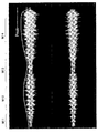
図1は、音響データを再生して得られる音声の波形の一例を示す図である。図1を参照しながら、音響データを再生して得られる音声の波形の一例について説明する。なお、図1には、音声波形のPeak値およびRMS(Root Mean Square)値のラインが示されているが、Peak値およびRMS値は、本発明の実施形態において、音量特性の一例として用いられ得るものである。また、RMS値は、音量平均値の一例として使用されるものである。
<1. Embodiment>
[1-1. Sound waveform obtained by playing back acoustic data]
FIG. 1 is a diagram illustrating an example of a sound waveform obtained by reproducing acoustic data. An example of a sound waveform obtained by reproducing acoustic data will be described with reference to FIG. FIG. 1 shows a peak value and RMS (Root Mean Square) line of a speech waveform. The Peak value and the RMS value are used as an example of a volume characteristic in the embodiment of the present invention. To get. The RMS value is used as an example of the volume average value.
ある音響データを再生して得られる音声の波形は、図1に示すように示される。ここで、図1に示された波形のうちの上側に示した波形は、音響データを再生して得られる音声を左(Lch)および右(Rch)のスピーカの双方から出力する方式(以下、「ステレオ音声方式」とも言う。)によりLchから出力された音声の波形を示したものである。また、図1に示された波形のうちの下側に示した波形は、ステレオ音声方式によりRchから出力された音声の波形を示したものである。音響データに対する補正は行われていない。 A sound waveform obtained by reproducing certain acoustic data is shown in FIG. Here, the waveform shown on the upper side of the waveforms shown in FIG. 1 is a method of outputting sound obtained by reproducing acoustic data from both the left (Lch) and right (Rch) speakers (hereinafter, referred to as “the sound”). This is also referred to as “stereo audio system”.) Shows the waveform of the audio output from the Lch. Further, the waveform shown at the lower side of the waveform shown in FIG. 1 shows the waveform of the sound output from the Rch by the stereo sound system. Correction for acoustic data is not performed.
図1に示された音声波形は、CD−DA形式(Compact Disc Digital Audio)により記録された音響データと同様の記録方式により記録された音響データを再生して得られたものである。CD−DA形式は、サンプリング周波数44.1kHz、量子化ビット数16bit、ステレオPCM(Pulse Code Modulation)形式により音響データを記録するものである。 The audio waveform shown in FIG. 1 is obtained by reproducing acoustic data recorded by the same recording method as the acoustic data recorded in the CD-DA format (Compact Disc Digital Audio). The CD-DA format records sound data in a sampling frequency of 44.1 kHz, a quantization bit number of 16 bits, and a stereo PCM (Pulse Code Modulation) format.
音響データが量子化ビット数16bit、PCM形式により記録されたものである場合、その音響データは、符号1bitおよびデータ15bitにより構成された2の補数コードにより表現される。この音響データにより表現できる音声の音量(振幅値)の最大値(あるいは最小値)は、正側で+32767、負側で−32768である。最小値から最大値までの範囲を超える音量の音声については最大値(あるいは最小値)に丸められることとなるが、その結果としてクリップノイズと呼ばれる不快な歪みが発生する可能性がある。 When the acoustic data is recorded in the PCM format with a quantization bit number of 16 bits, the acoustic data is represented by a two's complement code composed of a code of 1 bit and data of 15 bits. The maximum value (or minimum value) of the sound volume (amplitude value) that can be expressed by this acoustic data is +32767 on the positive side and −32768 on the negative side. Sound with a volume exceeding the range from the minimum value to the maximum value is rounded to the maximum value (or the minimum value). As a result, unpleasant distortion called clip noise may occur.
他方、音量が小さ過ぎる音声が音響データとして記録されている場合には、16bitの情報量を使い切れずに、音響データが再生された結果として良好なS/Nの音声が得られないこととなる。それゆえ、音響データの一例として楽曲を使用する場合には、楽曲の制作者は1曲を通して音量が16bitにより表現される範囲内に収まるようにミキサーなどの機器を用いて音量を調整しながら楽曲を録音する。 On the other hand, when a sound whose volume is too low is recorded as acoustic data, the 16-bit information amount is not used up, and as a result of reproducing the acoustic data, a good S / N sound cannot be obtained. . Therefore, when music is used as an example of acoustic data, the music producer adjusts the volume using a device such as a mixer so that the volume falls within the range expressed by 16 bits throughout the song. Record.
しかしながら、図1に示した音声波形を有する楽曲のように、市販されているCDもしくは楽曲ファイルの中には、全体を通して16bitにより表現できる値の最大値に音量が達しない楽曲が録音されていることもある。そのような楽曲が録音されている理由としては様々なものが想定されるが、録音技術が発達していなかった古い年代に録音された楽曲には、一般的にそのような傾向がある。 However, like the music having the audio waveform shown in FIG. 1, in the commercially available CD or music file, there is recorded music whose volume does not reach the maximum value that can be expressed by 16 bits throughout. Sometimes. There are various reasons why such music is recorded, but music recorded in an old age when recording technology was not developed generally has such a tendency.
図1に示した例は、他の楽曲と比べて比較的音量が小さいクラシック曲の音声波形である。このようなクラシック曲を単独で再生する場合には音量はさほど気にならないが、音量が比較的大きい楽曲の前後にこのようなクラシック曲を再生する場合は、このようなクラシック曲の音量が相対的に小さくなるため、音量の小ささが気になる可能性が高い。それゆえ、このクラシック曲の音量のみを上げたくなるという状況となり得る。 The example shown in FIG. 1 is an audio waveform of a classic song whose volume is relatively small compared to other songs. When playing such a classic song alone, the volume is not much of an issue, but when playing such a classic song before or after a relatively loud song, the volume of such a classic song is relative. Therefore, there is a high possibility that the volume is low. Therefore, it may be a situation where it is desired to increase only the volume of this classical song.
図1に示した音声波形を音声波形部分M11〜M14に分けた場合、音声波形部分M11は静かな部分であり、音声波形部分M12は徐々に盛り上がる部分であり、音声波形部分M13は静かな部分であり、音声波形部M14は盛り上がる部分である。上記したように、図1に示した音声波形はクラシック曲を再生して得られるものであり、聴く人に対して全体的に音量が小さいという印象を与え易いと想定される。そこで、このクラシック曲を再生する場合には、音声の音量を全体的に上げる必要があると考えられる。 When the speech waveform shown in FIG. 1 is divided into speech waveform portions M11 to M14, the speech waveform portion M11 is a quiet portion, the speech waveform portion M12 is a gradually rising portion, and the speech waveform portion M13 is a quiet portion. The voice waveform part M14 is a rising part. As described above, the audio waveform shown in FIG. 1 is obtained by playing a classical song, and it is assumed that it is easy to give the listener the impression that the overall volume is low. Therefore, when playing this classical music, it is considered necessary to increase the overall sound volume.
[1−2.一般的な音量補正技術による音量補正]
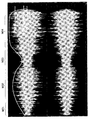
図2は、一般的な音量補正技術による音量補正を音響データに適用した場合において音響データを再生して得られる音声の波形の一例を示す図である。図2を参照しながら、一般的な音量補正技術による音量補正を音響データに適用した場合において音響データを再生して得られる音声の波形の一例について説明する。
[1-2. Volume correction using general volume correction technology]
FIG. 2 is a diagram illustrating an example of a sound waveform obtained by reproducing sound data when sound volume correction by a general sound volume correction technique is applied to the sound data. With reference to FIG. 2, an example of a sound waveform obtained by reproducing sound data when sound volume correction by a general sound volume correction technique is applied to the sound data will be described.
図2に示した音声波形を音声波形部分M21、M22に分けた場合、音声波形部分M21は一気に盛り上がる部分であり、音声波形部分M22は盛り上がりっぱなしによりメリハリがない部分である。図2に示すように、一般的な音量補正技術による音量補正により、上記したクラシック曲の音量は大きくなっているが、原曲が有する音量変化(以下、「音量カーブとも言う。」を維持することができておらず、聴く人に不自然な感じを与える結果となっている。 When the speech waveform shown in FIG. 2 is divided into speech waveform portions M21 and M22, the speech waveform portion M21 is a portion that rises all at once, and the speech waveform portion M22 is a portion that does not have sharpness due to the continued rise. As shown in FIG. 2, the volume of the classic song is increased by the volume correction by a general volume correction technique, but the volume change (hereinafter also referred to as “volume curve”) of the original song is maintained. The result is that the listener can feel unnatural.
また、一般的な音量補正技術による音量補正により、図2に示された音声波形からは把握できないような音声の歪みも発生している。聴く人に不自然な感じを与えることとなってしまった理由の1つは、音量増幅が音声波形全体を考慮してなされたものではなく、音声波形の一部を考慮して部分的に適切な音量増幅を行っていることが挙げられる。 Further, due to volume correction by a general volume correction technique, voice distortion that cannot be grasped from the voice waveform shown in FIG. 2 has also occurred. One of the reasons that caused the listener to feel unnatural is that the volume amplification was not done considering the entire speech waveform, but was partially appropriate considering a part of the speech waveform. It is mentioned that the sound volume is amplified.
[1−3.本発明の実施形態に係る再生装置による音量補正]
図3は、本発明の実施形態に係る再生装置による音量補正を音響データに適用した場合において音響データを再生して得られる音声の波形の一例を示す図である。図3を参照しながら、本発明の実施形態に係る再生装置による音量補正を音響データに適用した場合において音響データを再生して得られる音声の波形の一例について説明する。
[1-3. Volume correction by a playback apparatus according to an embodiment of the present invention]
FIG. 3 is a diagram illustrating an example of an audio waveform obtained by reproducing acoustic data when volume correction by the reproduction apparatus according to the embodiment of the present invention is applied to the acoustic data. With reference to FIG. 3, an example of an audio waveform obtained by reproducing acoustic data when volume correction by the reproduction apparatus according to the embodiment of the present invention is applied to the acoustic data will be described.
図3に示した音声波形を音声波形部分M31、M32、M33、M34に分けた場合、音声波形部分M31は静かな部分であり、音声波形部分M32は徐々に盛り上がる部分であり、音声波形部分M33は静かな部分であり、音声波形部分M34は徐々に盛り上がる部分である。図3に示すように、本発明の実施形態に係る再生装置による音量補正により、上記したクラシック曲の音量は大きくなっており、原曲が有する音量カーブを維持することができている。 When the speech waveform shown in FIG. 3 is divided into speech waveform portions M31, M32, M33, and M34, the speech waveform portion M31 is a quiet portion, the speech waveform portion M32 is a portion that gradually rises, and the speech waveform portion M33. Is a quiet part, and the voice waveform part M34 is a part that gradually rises. As shown in FIG. 3, the volume of the classic song is increased by the volume correction by the playback apparatus according to the embodiment of the present invention, and the volume curve of the original song can be maintained.
また、本発明の実施形態に係る再生装置による音量補正により、音声の歪みも軽減することができる。聴く人に自然な感じを与えるような音量補正を行うことが可能となった理由の1つは、音量増幅が音声波形全体を考慮してなされたものであることが挙げられる。音声波形全体を考慮して音量増幅を行うために、例えば、上記したPeak値およびRMS値などといったメタデータを使用することができる。Peak値およびRMS値などのメタデータは、例えば、サーバに保持させておき、再生装置にダウンロードして使用することができる。 In addition, sound distortion can be reduced by the volume correction by the playback device according to the embodiment of the present invention. One reason why the volume correction that gives a natural feeling to the listener can be performed is that the volume amplification is performed in consideration of the entire speech waveform. In order to perform volume amplification in consideration of the entire audio waveform, for example, metadata such as the above-described Peak value and RMS value can be used. Metadata such as Peak value and RMS value can be stored in a server and downloaded to a playback device for use.
[1−4.音量特性値の一例としてのPeak値およびRMS値]
図4は、本発明の実施形態に係る音量特性値の一例としてのPeak値およびRMS値について説明するための図である。図4を参照しながら、本発明の実施形態に係る音量特性値の一例としてのPeak値およびRMS値について説明する。
[1-4. Peak value and RMS value as an example of volume characteristic value]
FIG. 4 is a diagram for explaining the Peak value and the RMS value as an example of the volume characteristic value according to the embodiment of the present invention. With reference to FIG. 4, the Peak value and the RMS value as an example of the volume characteristic value according to the embodiment of the present invention will be described.
図4に示すように、1箇所だけ突発的な衝撃音のような大きな音があり、それ以外は歌声のみが含まれている楽曲が録音されていたとする。このような楽曲は、一般的にはダイナミックレンジの広い音と呼ばれる。衝撃音の音量が最大音量に相当し、16bitにより表現できる値の最大値に相当するため、衝撃音以外の音声については相対的に音量を下げて録音せざるを得ない。 As shown in FIG. 4, it is assumed that there is a loud sound such as a sudden impact sound at one place, and a music piece that includes only the singing voice is recorded. Such music is generally called a sound with a wide dynamic range. Since the volume of the impact sound corresponds to the maximum volume and corresponds to the maximum value that can be expressed by 16 bits, it is necessary to record the sound other than the impact sound with a relatively low volume.
例えば、衝撃音のPeak値が+32767であった場合は、衝撃音以外の音声に相当する歌声などの音量はPeak値を+1000くらいまで下げて録音しないと、楽曲全体が16bitに収まらない。このようなケースでは、衝撃音以外の音声に相当する歌声の音量が、相対的にかなり小さく感じられてしまう。 For example, if the peak value of the impact sound is +32767, the volume of the singing voice corresponding to the sound other than the impact sound cannot be recorded within 16 bits unless the peak value is reduced to about +1000 and recorded. In such a case, the volume of the singing voice corresponding to the sound other than the impact sound is felt relatively small.
このような背景から、本発明の実施形態に係る再生システムは、例えば、楽曲の音量を表す特徴量としてPeak値およびRMS値の2つを保持することとしている。Peak値は、楽曲1曲の中に出現する突発的な音量変化が生じたときの音量レベルを表す特徴量として用いるのに適していると言える。図4に示した例では、Peak値は、衝撃音の音量レベルを表現するのに適していると言える。また、RMS値は、楽曲の音声が有するパワーに対する積分値の時間平均を表すものであり、楽曲全体の平均的な音量レベルを表す特徴量として用いるのに適していると言える。図4に示した例においては、RMS値は、主に衝撃音以外の音声に相当する歌声の音量レベルを表す特徴量となっている。 From such a background, the playback system according to the embodiment of the present invention holds, for example, two Peak values and RMS values as feature amounts representing the volume of music. It can be said that the Peak value is suitable for use as a feature value representing a volume level when a sudden volume change that appears in one piece of music occurs. In the example shown in FIG. 4, the Peak value can be said to be suitable for expressing the volume level of the impact sound. Further, the RMS value represents the time average of the integral value with respect to the power possessed by the sound of the music, and can be said to be suitable for use as a feature value representing the average volume level of the entire music. In the example illustrated in FIG. 4, the RMS value is a feature amount that mainly represents the volume level of a singing voice corresponding to a sound other than the impact sound.
[1−5.音量特性値の一例としてのPeak値の計算例]
図5は、本発明の実施形態に係る音量特性値の一例としてのPeak値の計算例を示す図である。図5を参照しながら、本発明の実施形態に係る音量特性値の一例としてのPeak値の計算例について説明する。
[1-5. Calculation example of Peak value as an example of volume characteristic value]
FIG. 5 is a diagram illustrating a calculation example of the Peak value as an example of the volume characteristic value according to the embodiment of the present invention. A calculation example of the Peak value as an example of the volume characteristic value according to the embodiment of the present invention will be described with reference to FIG.
音響データの一例としての楽曲1曲をモノラル音声により再生した場合、例えば、図5に示した式1のような関数により計算を行うことにより、変数PeakにPeak値が格納される。また、音響データの一例としての楽曲1曲をステレオ音声により再生した場合、例えば、図5に示した式2のような関数により計算を行うことにより、変数PeakにPeak値が格納される。本発明の実施形態に係る再生システムは、例えば、このような計算により変数PeakにPeak値を格納し、変数Peakに格納したPeak値を音量特性値の一例として使用することができる。
When one piece of music as an example of acoustic data is reproduced with monaural sound, for example, the Peak value is stored in the variable Peak by performing calculation using a function such as
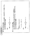
[1−6.音量特性値の一例としてのRMS値の計算例]
図6は、本発明の実施形態に係る音量特性値の一例としてのRMS値の計算例を示す図である。図6を参照しながら、本発明の実施形態に係る音量特性値の一例としてのRMS値の計算例について説明する。
[1-6. Example of RMS value calculation as an example of volume characteristic value]
FIG. 6 is a diagram illustrating a calculation example of the RMS value as an example of the volume characteristic value according to the embodiment of the present invention. A calculation example of the RMS value as an example of the volume characteristic value according to the embodiment of the present invention will be described with reference to FIG.
音響データの一例としての楽曲1曲をモノラル音声により再生した場合、例えば、図6に示した式3のような関数により計算を行うことにより、変数RMSにRMS値が格納される。また、音響データの一例としての楽曲1曲をステレオ音声により再生した場合、例えば、図6に示した式2のような関数により計算を行うことにより、変数RMSにRMS値が格納される。本発明の実施形態に係る再生システムは、例えば、このような計算により変数RMSにRMS値を格納し、変数RMSに格納したRMS値を音量特性値の一例として使用することができる。
When one piece of music as an example of acoustic data is reproduced with monaural sound, the RMS value is stored in the variable RMS, for example, by calculating with a function such as Equation 3 shown in FIG. Further, when one piece of music as an example of acoustic data is reproduced with stereo sound, the RMS value is stored in the variable RMS, for example, by performing calculation using a function such as
[1−7.再生装置のハードウェア構成]
図7は、本発明の実施形態に係る再生装置のハードウェア構成例を示す図である。図7を参照しながら、本発明の実施形態に係る再生装置のハードウェア構成例について説明する。
[1-7. Hardware configuration of playback device]
FIG. 7 is a diagram illustrating a hardware configuration example of the playback device according to the embodiment of the present invention. A hardware configuration example of the playback apparatus according to the embodiment of the present invention will be described with reference to FIG.
図7に示すように、本発明の実施形態に係る再生装置100は、例えば、CPU(Central Processing Unit)910と、ROM(Read Only Memory)920と、RAM(Random Access Memory)930と、バス940と、ユーザインタフェース950と、記憶装置960と、通信装置970と、デコード回路980と、を備えるものである。
As shown in FIG. 7, the
CPU910は、演算処理装置および制御装置として機能し、例えば、ROM920に記録された各種プログラムを読み出して記憶装置960に記憶させておき、各種プログラムを実行するに際して、記憶装置960により記憶された各種プログラムをRAM930に展開し、RAM930に展開した各種プログラムを実行することができる。かかる各種プログラムの実行により、再生装置100内の動作全般またはその一部を制御することが可能である。
The
ROM920は、読み出し専用のメモリであり、例えば、CPU910により読み出される各種プログラムやその実行に使用されるパラメータなどを記憶することができる。
The
RAM930は、記憶装置960からCPU910により読み出された各種プログラムやその実行に使用されるパラメータなどを一時的に記憶することが可能である。また、CPU910による各種プログラムの実行に際して一時的に記憶しておく必要が生じた各種データなどを記憶することも可能である。
The
バス940は、再生装置100の内部に設けられている各ハードウェアを接続し、各ハードウェア間における信号の送受信を実現するために機能する。
The
ユーザインタフェース950は、入力装置により構成されるものである。例えば、マウス、キーボード、タッチパネル、ボタン、スイッチおよびレバーなどにより構成され、ユーザからの操作を受け付ける機能を有する。入力装置は、例えば、受け付けた操作に基づいて入力信号を生成し、CPU910に出力する。音響データを再生して得られる音声を聴いている人は、例えば、入力装置を操作することにより、再生装置100に対して各種のデータを入力したり処理動作を指示したりすることができる。
The
記憶装置960は、記憶装置960は、データ格納用の装置であり、例えば、HDDなどの磁気記憶部デバイス、半導体記憶デバイス、光記憶デバイス、または光磁気記憶デバイス等により構成される。記憶装置960は、外部から取得した音響データや画像データなどを格納することができる。記憶装置960は、例えば、CPU910によりROM920から読み出された各種プログラムを記憶しておく機能などを有するものである。
The
通信装置970は、例えば、ネットワークに接続するための通信デバイス等で構成された通信インタフェースである。通信装置970は、例えば、有線または無線LAN(Local Area Network)用の通信カード、ADSL(Asymmetric Digital Subscriber Line)用のルータ、各種通信用のモデムなどにより構成される。この通信装置970は、例えば、他の通信機器との間で音響データなどのデータを送受信することができる。また、通信装置970に接続されるネットワークは、有線または無線によって接続されたネットワークなどにより構成され、例えば、インターネット、家庭内LANなどであってもよい。
The
デコード回路980は、符号化された音響データを復号し、再生する機能を有するものである。また、デコード回路980は、符号化された映像データを復号し、再生する機能を有していてもよい。
The
以上、本発明の実施形態に係る再生装置100の機能を実現可能なハードウェア構成の一例を示した。上記の各構成要素は、汎用的な部材を用いて構成されていてもよいし、各構成要素の機能に特化したハードウェアにより構成されていてもよい。従って、本発明の実施形態に係る再生装置100を実施する時の技術レベルに応じて、適宜、利用するハードウェア構成を変更することが可能である。
Heretofore, an example of the hardware configuration capable of realizing the function of the
[1−8.再生システムの機能構成]
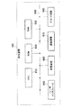
図8は、本発明の実施形態に係る再生システムの機能構成を示す図である。図8を参照しながら、本発明の実施形態に係る再生システムの機能構成について説明する。
[1-8. Functional configuration of playback system]
FIG. 8 is a diagram showing a functional configuration of the reproduction system according to the embodiment of the present invention. The functional configuration of the playback system according to the embodiment of the present invention will be described with reference to FIG.
図8に示すように、本発明の実施形態に係る再生システム10は、再生装置100と、提供装置200と、出力装置300とを備えるものである。再生装置100と提供装置200とは、例えば、ネットワークを介して接続されており、互いに通信可能とされている。再生装置100と出力装置300とは、例えば、専用線により接続されており、出力装置300は、再生装置100から出力された音声信号を音声として出力することが可能である。また、出力装置300は、再生装置100から出力された画像信号を画像として出力することが可能である。
As shown in FIG. 8, the
再生装置100は、少なくとも、再生部の一例としての映像音響データデコード回路130(以下、単に「映像音響データデコード回路130」とも言う。)と、音量補正部の一例としてのコンプレッサー回路160(以下、単に「コンプレッサー回路160」とも言う。)を備えるものである。ここでは、再生装置100は、映像音響データデコード回路130を備えることとしており、映像音響データデコード回路130は、符号化された映像データと符号化された音響データとの双方を復号して再生することとする。しかしながら、再生装置100は、再生部は、符号化された映像データを復号して再生する機能は有していなくてもよい。映像音響データデコード回路130は、例えば、上記したデコード回路980により構成される。
The
コンプレッサー回路160は、映像音響データデコード回路130により再生された音響データ(以下、「再生対象音響データ」とも言う。)の音量を、複数の音響データの各々の音量特性値と再生対象音響データの音量特性値との関係に基づいて補正する機能を有するものである。複数の音響データは、特に限定されるものではなく、再生対象音響データを含むものであってもよいし、含まないものであってもよい。音量特性値としては、Peak値やRMS値などを例として挙げることができる。
The
再生装置100は、映像音響データデコード回路130と、コンプレッサー回路160とを備えることにより、元の音響データの音量変化に比較的近い音量変化を維持しつつ各音響データ間の音量の違いを低減させ、音量増幅による音声の歪みを低減させながら音響データを再生することが可能となる。
The
再生装置100は、パラメータ算出部150を備えることとしてもよい。パラメータ算出部150は、複数の音響データの各々の音量特性値と音響データの音量特性値との関係に基づいて音量補正のためのパラメータを算出する機能を有するものである。音量補正のためのパラメータは、コンプレッサー回路160において音響データの音量補正に使用される。すなわち、コンプレッサー回路160は、パラメータ算出部150により算出されたパラメータに従って再生対象音響データの音量を補正する。
The
再生装置100は、受信部110、映像音響データ取得部120、映像音響データデコード回路130、属性情報取得部140、ミキサー装置170、記憶部180などを備えることとしてもよい。受信部110は、提供装置200から、上記した複数の音響データの各々の音量特性値、再生対象音響データの音量特性値、再生対象音響データ自体などを受信することが可能である。しかしながら、上記した複数の音響データの各々の音量特性値、再生対象音響データの音量特性値、再生対象音響データ自体などは、提供装置200から受信せずに、再生装置100が備える記憶部180により記憶されているものを再生装置100において使用することもできる。受信部110は、提供装置200から映像データを受信することとしてもよい。受信部110は、例えば、通信装置970により構成されるものである。
The
映像音響データ取得部120は、受信部110により受信された再生対象音響データを受信部110から取得する機能を有するものである。映像音響データ取得部120は、取得した再生対象音響データを映像音響データデコード回路130に出力する機能をさらに有している。映像音響データ取得部120は、受信部110により映像データが受信された場合には、その映像データを受信部110から取得する機能を有していてもよい。その場合には、映像音響データ取得部120は、受信部110から取得した映像データを映像音響データデコード回路130に出力する機能をさらに有する。映像音響データデコード回路130に出力された再生対象音響データや映像データは、映像音響データデコード回路130において使用される。
The audiovisual
属性情報取得部140は、受信部110により受信された再生対象音響データの音量特性値を受信部110から取得する機能を有するものである。属性情報取得部140は、受信部110により受信された再生対象音響データの音量特性値をパラメータ算出部150に出力する機能をさらに有している。パラメータ算出部150に出力された再生対象音響データの音量特性値は、パラメータ算出部150において使用される。属性情報取得部140は、再生対象音響データの音量特性値を再生対象音響データの属性情報(「メタデータ」とも言う。以下同じ。)として属性情報取得部140から受信することができる。
The attribute
ミキサー装置170は、コンプレッサー回路160から出力された再生対象音響データおよび映像データを合成する機能を有するものである。コンプレッサー回路160から出力された再生対象音響データは、必要に応じて音量が補正されている。ミキサー装置170は、再生対象音響データおよび映像データが合成されてなる合成信号を出力装置300に出力する。
The
再生装置100は、記憶部180をさらに備えることとしてもよい。記憶部180は、例えば、記憶装置960によって構成されるものである。記憶部180は、再生装置100を構成する各機能ブロックの動作を制御するための各種プログラムを記憶する機能や、そのプログラムが実行される際に使用される各種データなどを記憶する機能を有するものである。
The
映像音響データ取得部120や、属性情報取得部140、パラメータ算出部150などは、例えば、CPU910、RAM930などにより構成され、CPU910が記憶部180によって記憶されているプログラムをRAM930に展開して実行することによりその機能が実現されるものである。しかし、このような構成に限らず、映像音響データ取得部120や、属性情報取得部140、パラメータ算出部150の中には、専用のハードウェアにより構成されるものが存在してもよい。
The audiovisual
提供装置200は、少なくとも、記憶部210と、取得部220と、解析部230と、送信部240とを備えるものである。記憶部210は、例えば、記憶装置によって構成されるものである。記憶部180は、提供装置200を構成する各機能ブロックの動作を制御するための各種プログラムを記憶する機能や、そのプログラムが実行される際に使用される各種データなどを記憶する機能を有するものである。記憶部180は、例えば、上記した複数の音響データの各々の音量特性値を記憶する機能を有していてもよい。また、記憶部180は、再生対象音響データを記憶する機能を有していてもよい。
The providing
取得部220は、複数の音響データの各々の音量特性値を取得する機能を有するものである。取得部220は、例えば、記憶部180により記憶されている複数の音響データの各々の音量特性値を取得する。複数の音響データの各々の音量特性値としては、例えば、複数の音響データの各々のRMS値を使用することができる。また、取得部220は、再生対象音響データを取得する機能を有するものである。取得部220は、例えば、記憶部180により記憶されている再生対象音響データを取得する。
The
解析部230は、取得部220により取得された複数の音響データの各々の音量特性値の分布を解析する機能を有するものである。複数の音響データの各々の音量特性値の分布としては、例えば、複数の音響データの各々のRMS値の分布を使用することができる。解析部230は、複数の音響データの各々の音量特性値の分布を解析することにより、RMS基準値を解析結果として算出してもよい。RMS基準値の算出手法については、後に詳細に説明する。解析部230により複数の音響データの各々の音量特性値の分布が解析されて得られた結果は、解析結果の一例として送信部240に出力される。RMS基準値は、基準平均値の一例である。
The
また、解析部230は、取得部220により取得された再生対象音響データを解析する機能をさらに有するものである。解析部230は、再生対象音響データを解析することにより、再生対象音響データの音量特性値を算出してもよい。また、解析部230は、再生対象音響データの音量特性値の一例として、再生対象音響データのRMS値を算出してもよい。解析部230は、このように解析して得られた再生対象音響データの音量特性値を、例えば、再生対象音響データの属性情報として記憶部210に記憶させておき、必要に応じて記憶部210から取得できるようにしておくこともできる。解析部230により再生対象音響データが解析されて得られた結果は、解析結果の一例として送信部240に出力される。
The
ここでは、解析部230は、複数の音響データの各々の音量特性値の分布を解析して得た結果と、再生対象音響データを解析して得た結果とを、解析結果として送信部240に出力することとしている。しかしながら、解析部230は、これらの解析結果を用いてさらに解析を進め、その結果として得られた解析結果を送信部240に出力するようにしてもよい。例えば、解析部230は、解析をさらに進めた結果として、音量補正のためのパラメータを算出することとしてもよい。かかる場合には、当該パラメータを解析結果の一例として送信部240に出力することとしてもよい。音量補正のためのパラメータについては、後に詳細に説明する。
Here, the
送信部240は、再生対象音響データを再生する再生装置100に対して、再生対象音響データ、および解析部230による解析結果を送信する機能を有するものである。送信部240は、例えば、取得部220により記憶部210から取得された再生対象音響データを再生装置100に送信することができる。送信部240は、例えば、通信装置により構成されるものである。送信部240は、記憶部210により映像データが記憶されている場合には、記憶部210により記憶されている映像データを再生装置100に送信し、再生させることとしてもよい。
The
取得部220や、解析部230などは、例えば、CPU、RAMなどにより構成され、CPUが記憶部210によって記憶されているプログラムをRAMに展開して実行することによりその機能が実現されるものである。しかし、このような構成に限らず、取得部220や、解析部230の中には、専用のハードウェアにより構成されるものが存在してもよい。
The
出力装置300は、少なくとも、音声出力部310を備えるものである。音声出力部310は、例えば、スピーカまたはヘッドホンによって構成されるものである。音声出力部310は、映像音響データデコード回路130により再生された音響データをアナログ信号に変換して出力する機能を有している。出力装置300は、画像出力部320を有していてもよい。画像出力部320は、例えば、表示装置によって構成されるものである。画像出力部320は、映像音響データデコード回路130により再生された映像データをアナログ信号に変換して出力する機能を有している。
The
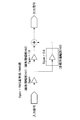
[1−9.属性情報の管理手法の一例]
図9は、本発明の実施形態に係る属性情報の管理手法の一例について説明するための図である。図9を参照しながら、本発明の実施形態に係る属性情報の管理手法の一例について説明する。
[1-9. Example of attribute information management method]
FIG. 9 is a diagram for explaining an example of the attribute information management method according to the embodiment of the present invention. An example of the attribute information management method according to the embodiment of the present invention will be described with reference to FIG.
図9に示すように、再生対象音響データの属性情報は、提供装置200が備える記憶部210に記憶されている再生対象音響データと同一の楽曲ファイルにヘッダデータとして埋め込まれていることとしてもよい。解析部230は、例えば、上記した解析結果を属性情報として楽曲ファイルにヘッダデータとして埋め込んでおけばよい。そのようにすれば、提供装置200は、再生装置100からの再生対象音響データの送信要求に応じて、取得部220により属性情報が埋め込まれた楽曲ファイルを取得し、送信部240により再生装置100に送信すればよい。
As shown in FIG. 9, the attribute information of the reproduction target acoustic data may be embedded as header data in the same music file as the reproduction target acoustic data stored in the
[1−10.属性情報の管理手法の他の一例]
図10は、本発明の実施形態に係る属性情報の管理手法の他の一例について説明するための図である。図10を参照しながら、本発明の実施形態に係る属性情報の管理手法の他の例について説明する。
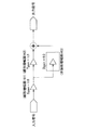
[1-10. Another example of attribute information management method]
FIG. 10 is a diagram for explaining another example of the attribute information management method according to the embodiment of the present invention. Another example of the attribute information management method according to the embodiment of the present invention will be described with reference to FIG.
図10に示すように、再生対象音響データの属性情報は、提供装置200が備える記憶部210に記憶されている再生対象音響データと同一の楽曲ファイルに埋め込まれていなくてもよい。解析部230は、例えば、上記した解析結果を属性情報として再生対象音響データに紐付けをして記憶部210に記憶させておけばよい。提供装置200は、例えば、再生対象音響データを識別するための情報と属性情報とを対応付けて記憶部210に記憶しておく。
As illustrated in FIG. 10, the attribute information of the reproduction target acoustic data may not be embedded in the same music file as the reproduction target acoustic data stored in the
一方、再生装置100は、必要に応じて、再生対象音響データを識別するための情報を含む要求を提供装置200に送信し、その要求に対する応答として再生対象音響データを識別するための情報に対応する属性情報を取得することができる。再生対象音響データを識別するための情報としては、例えば、再生対象音響データの一部を解析して得られる情報(Fingerprint)を使用することができる。
On the other hand, the
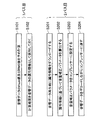
[1−11.再生システムにより実行される処理]
図11は、本発明の実施形態に係る再生システムにより実行される処理の流れを示すフローチャートである。図11を参照しながら、本発明の実施形態に係る再生システム10により実行される処理の流れについて説明する。
[1-11. Processing executed by playback system]
FIG. 11 is a flowchart showing a flow of processing executed by the reproduction system according to the embodiment of the present invention. With reference to FIG. 11, the flow of processing executed by the
図11に示すように、提供装置200の解析部230は、再生対象音響データのPeak値およびRMS値を予め計算しておくことができる(ステップS101)。再生対象音響データのPeak値およびRMS値は、再生対象音響データの音量特性値の例に相当する。続いて、記憶部210は、解析部230により計算された再生対象音響データのPeak値およびRMS値を再生対象音響データと対応付けて属性情報として保持しておくことができる(ステップS102)。計算結果と再生対象音響データとの対応付けについては、上記したように様々な手法が想定される。ステップS101およびステップS102は、再生システム10において1パス目の処理として実行され得るものである。記憶部210がこのように属性情報を保持しておき、必要に応じて取得されるようにしておけば、同一の再生対象音響データを次回以降に再生する際に再度1パス目の処理を実行する必要はなくなるという利点がある。
As illustrated in FIG. 11, the
続いて、再生装置100の受信部110は、映像音響データデコード回路130による再生対象音響データの再生前に再生対象音響データの属性情報をダウンロードする(ステップS201)。再生装置100のパラメータ算出部150は、この属性情報に基づいて音量補正パラメータを算出し(ステップS202)、算出した音量補正パラメータをコンプレッサー回路160に設定する(ステップS203)。映像音響データデコード回路130は、再生対象音響データをデコードしながらコンプレッサー回路160に通す(ステップS204)。ステップS201〜ステップS204は、再生システム10において2パス目の処理として実行され得るものである。2パス目の処理を実行すると、音量が補正された後の再生対象音響データが出力される。
Subsequently, the
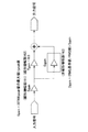
[1−12.音響データの音量補正に適用し得るコンプレッサー回路]
図12は、本発明の実施形態に係る再生装置100による音響データの音量補正に適用し得るコンプレッサー回路を示す図である。図12を参照しながら、本発明の実施形態に係る再生装置100による音響データの音量補正に適用し得るコンプレッサー回路160について説明する。
[1-12. Compressor circuit applicable to sound volume correction]
FIG. 12 is a diagram illustrating a compressor circuit that can be applied to sound volume correction of acoustic data by the
図12に示すように、コンプレッサー回路160は、映像音響データデコード回路130から入力された信号の大きさが出力目標レベルになるように信号を調整し、調整後の信号を出力信号として出力する。本発明の実施形態に係るコンプレッサー回路160は、既存のコンプレッサー回路とは異なり、例えば、線形増幅部161および非線形増幅部163を有している。また、コンプレッサー回路160は、例えば、線形増幅部161の後段に非線形増幅部163と並列に接続される線形増幅部162を有しており、かかるコンプレッサー回路160を有することは、本発明の実施形態に係る再生装置100の特徴の1つである。これらの増幅部をメタデータにより適切に制御することで、制作者の意図する元の音響データの音量変化カーブを維持しつつ各音響データ間の音量の違いを低減させ、音量増幅による音声の歪みを低減させながら音響データを再生することが可能となる。以下、映像音響データデコード回路130から入力される信号が音声信号(例えば、再生対象音響データの音声信号)であるとして説明する。
As shown in FIG. 12, the
線形増幅部161は、第1の線形補正部の一例として機能し、図12においては「Sgain」と表されている。また、線形増幅部162は、第2の線形補正部の一例として機能し、図12においては「Tgain」と表されている。また、非線形増幅部163は、非線形補正部の一例として機能し、図12においては「Dgain」と表されている。「Sgain」「Tgain」「Dgain」は、各増幅部における増幅率を示している。 The linear amplification unit 161 functions as an example of a first linear correction unit, and is represented as “Sgain” in FIG. The linear amplification unit 162 functions as an example of a second linear correction unit, and is represented as “Tgain” in FIG. The nonlinear amplifier 163 functions as an example of a nonlinear corrector, and is represented as “Dgain” in FIG. “Sgain”, “Tgain”, and “Dgain” indicate the amplification factor in each amplification unit.
線形増幅部161は、音声信号に対して線形の増幅処理を施すものである。線形増幅部162は、線形増幅部161から出力された音声信号に対して線形の増幅処理を施すものである。非線形増幅部163は、線形増幅部161から出力された音声信号に対して非線形の増幅処理を施すものであり、主に音声レベルの高い音声波形への振幅圧縮処理を行う。その振幅圧縮処理は、非線形処理により行われるため、音声に歪みが生じ、振幅圧縮率が高まるにつれ、その歪み率が大きくなってしまう。 The linear amplification unit 161 performs linear amplification processing on the audio signal. The linear amplification unit 162 performs linear amplification processing on the audio signal output from the linear amplification unit 161. The non-linear amplification unit 163 performs non-linear amplification processing on the audio signal output from the linear amplification unit 161, and mainly performs amplitude compression processing on an audio waveform having a high audio level. Since the amplitude compression processing is performed by non-linear processing, distortion occurs in the sound, and the distortion rate increases as the amplitude compression rate increases.
[1−13.コンプレッサー回路が有する静特性(音量増幅時)の一例]
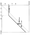
図13は、本発明の実施形態に係る再生装置100に適用し得るコンプレッサー回路160内の非線形増幅部163が有する静特性(音響データの音量を増幅する場合)の一例を示す図である。図13を参照しながら、本発明の実施形態に係る再生装置100に適用し得るコンプレッサー回路160内の非線形増幅部163が有する静特性(音響データの音量を増幅する場合)の一例について説明する。
[1-13. Example of static characteristics of compressor circuit (when volume is amplified)]
FIG. 13 is a diagram illustrating an example of a static characteristic (in the case of amplifying the volume of acoustic data) included in the non-linear amplification unit 163 in the
図13に示したグラフは、特に、再生対象音響データの音量を増幅する場合において、非線形増幅部163(増幅率Dgainを有する増幅部)が有する静特性を示したものである。図13には、非線形増幅部163に対して入力される信号の大きさと非線形増幅部163から出力される信号の大きさとの関係が示されている。非線形増幅部163が有する動特性を考慮する場合には、図13に示された非線形増幅部163から出力される信号の大きさは、当該大きさを有する信号になるように非線形増幅部163により制御される出力目標レベルとしての意味を持つ。 The graph shown in FIG. 13 shows the static characteristics of the nonlinear amplifying unit 163 (amplifying unit having the amplification factor Dgain), particularly when the volume of the acoustic data to be reproduced is amplified. FIG. 13 shows the relationship between the magnitude of the signal input to the nonlinear amplifier 163 and the magnitude of the signal output from the nonlinear amplifier 163. When considering the dynamic characteristics of the nonlinear amplifying unit 163, the magnitude of the signal output from the nonlinear amplifying unit 163 shown in FIG. It has the meaning as the output target level to be controlled.
図13に示した例では、非線形増幅部163への入力信号の大きさがTに達するまでは、入力信号の大きさの増分に比例して非線形増幅部163からの出力信号の大きさの増分が変化する。また、非線形増幅部163への入力信号の大きさがTを超えると、非線形増幅部163からの出力信号の大きさの増分が0dBに飽和する。非線形増幅部163への入力信号の大きさがTに達するまでは、非線形増幅部163からの出力信号の大きさは、非線形増幅部163への入力信号の大きさに増幅率Dgainを乗じた分だけ大きい値となっている。非線形増幅部163への入力信号の大きさがTに達するまでは、音声信号に対して非線形な増幅が行われていることになる。 In the example shown in FIG. 13, until the magnitude of the input signal to the nonlinear amplifier 163 reaches T, the magnitude of the output signal from the nonlinear amplifier 163 is proportional to the magnitude of the input signal. Changes. When the magnitude of the input signal to the nonlinear amplifier 163 exceeds T, the increase in the magnitude of the output signal from the nonlinear amplifier 163 is saturated to 0 dB. Until the magnitude of the input signal to the nonlinear amplifying section 163 reaches T, the magnitude of the output signal from the nonlinear amplifying section 163 is equal to the magnitude of the input signal to the nonlinear amplifying section 163 multiplied by the amplification factor Dgain. Only a large value. Until the magnitude of the input signal to the nonlinear amplifier 163 reaches T, nonlinear amplification is performed on the audio signal.
[1−14.コンプレッサー回路が有する静特性(音量減衰時)の一例]
図14は、本発明の実施形態に係る再生装置100に適用し得るコンプレッサー回路160内の非線形増幅部163が有する静特性(音響データの音量を減衰する場合)の一例を示す図である。図14を参照しながら、本発明の実施形態に係る再生装置100に適用し得るコンプレッサー回路160内の非線形増幅部163が有する静特性(音響データの音量を減衰する場合)の一例について説明する。
[1-14. Example of static characteristics of compressor circuit (when volume is attenuated)]
FIG. 14 is a diagram illustrating an example of a static characteristic (in the case where the volume of acoustic data is attenuated) included in the nonlinear amplifier 163 in the
図14に示したグラフは、特に、再生対象音響データの音量を減衰する場合において、非線形増幅部163(増幅率Dgainを有する増幅部)が有する静特性を示したものである。図14には、非線形増幅部163に対して入力される信号の大きさと非線形増幅部163から出力される信号の大きさとの関係が示されている。非線形増幅部163が有する動特性を考慮する場合には、図14に示された非線形増幅部163から出力される信号の大きさは、当該大きさを有する信号になるように非線形増幅部163により制御される出力目標レベルとしての意味を持つ。 The graph shown in FIG. 14 shows the static characteristics of the nonlinear amplifying unit 163 (amplifying unit having the amplification factor Dgain) particularly when the volume of the sound data to be reproduced is attenuated. FIG. 14 shows the relationship between the magnitude of the signal input to the nonlinear amplifier 163 and the magnitude of the signal output from the nonlinear amplifier 163. When considering the dynamic characteristics of the nonlinear amplifying unit 163, the magnitude of the signal output from the nonlinear amplifying unit 163 shown in FIG. It has the meaning as the output target level to be controlled.
図14に示した例では、非線形増幅部163からの出力信号の大きさは、非線形増幅部163への入力信号の大きさに増幅率Dgainを乗じた分だけ小さい値となっている。非線形増幅部163への入力信号の大きさがTに達するまでは、音声信号に対して非線形な増幅が行われていることになる。図14に示した場合のように、音声信号の音量を減衰する場合には、音声信号に対して線形減衰を施すこととなるため、音声に歪みが発生することは考慮しなくてよい。 In the example shown in FIG. 14, the magnitude of the output signal from the nonlinear amplifying unit 163 is a small value corresponding to the magnitude of the input signal to the nonlinear amplifying unit 163 multiplied by the amplification factor Dgain. Until the magnitude of the input signal to the nonlinear amplifier 163 reaches T, nonlinear amplification is performed on the audio signal. As shown in FIG. 14, when the volume of the audio signal is attenuated, linear attenuation is applied to the audio signal, so that it is not necessary to consider the occurrence of distortion in the audio.
[1−15.コンプレッサー回路が有する静特性(音量増幅時)の他の一例]
図15は、本発明の実施形態に係る再生装置100に適用し得るコンプレッサー回路160内の非線形増幅部163が有する静特性(音響データの音量を増幅する場合)の他の一例を示す図である。図15を参照しながら、本発明の実施形態に係る再生装置100に適用し得るコンプレッサー回路160内の非線形増幅部163が有する静特性(音響データの音量を増幅する場合)の他の一例について説明する。
[1-15. Another example of static characteristics of compressor circuit (when volume is amplified)]
FIG. 15 is a diagram illustrating another example of static characteristics (in the case of amplifying the volume of acoustic data) included in the nonlinear amplifier 163 in the
図15に示したグラフは、特に、再生対象音響データの音量を増幅する場合において、非線形増幅部163(増幅率Dgainを有する増幅部)が有する静特性を示したものであり、図13を参照しながら説明した静特性に代わって使用される例であり、図13に示した静特性と図14に示した静特性との複合型に相当するものである。図15には、非線形増幅部163に対して入力される信号の大きさと非線形増幅部163から出力される信号の大きさとの関係が示されている。非線形増幅部163が有する動特性を考慮する場合には、図15に示された非線形増幅部163から出力される信号の大きさは、当該大きさを有する信号になるように非線形増幅部163により制御される出力目標レベルとしての意味を持つ。 The graph shown in FIG. 15 shows the static characteristics of the nonlinear amplifying unit 163 (amplifying unit having an amplification factor Dgain), particularly when the volume of the acoustic data to be reproduced is amplified, see FIG. However, this example is used in place of the static characteristics described above, and corresponds to a composite type of the static characteristics shown in FIG. 13 and the static characteristics shown in FIG. FIG. 15 shows the relationship between the magnitude of the signal input to the nonlinear amplifier 163 and the magnitude of the signal output from the nonlinear amplifier 163. When considering the dynamic characteristics of the nonlinear amplifying unit 163, the magnitude of the signal output from the nonlinear amplifying unit 163 shown in FIG. 15 is set by the nonlinear amplifying unit 163 so that the signal has the magnitude. It has the meaning as the output target level to be controlled.
図15に示した例では、非線形増幅部163への入力信号の大きさがT1に達するまでは、比較的大きな増幅率により入力信号の大きさの増分に比例して非線形増幅部163からの出力信号の大きさの増分が変化する。また、非線形増幅部163への入力信号の大きさがT1を超えると、非線形増幅部163からの出力信号の大きさの増分が低下していく。非線形増幅部163への入力信号の大きさがT2を超えてからは、非線形増幅部163からの出力信号の大きさは、非線形増幅部163への入力信号の大きさよりも低くなり、音声信号に対して非線形な増幅が行われていることになる。かかる増幅処理も振幅圧縮処理に相当し、音声に歪みが生じ得る。 In the example shown in FIG. 15, until the magnitude of the input signal to the nonlinear amplifier 163 reaches T1, the output from the nonlinear amplifier 163 is proportional to the increase in the magnitude of the input signal with a relatively large amplification factor. The signal magnitude increment changes. Further, when the magnitude of the input signal to the nonlinear amplifying unit 163 exceeds T1, the increase in the magnitude of the output signal from the nonlinear amplifying unit 163 decreases. After the magnitude of the input signal to the nonlinear amplifying section 163 exceeds T2, the magnitude of the output signal from the nonlinear amplifying section 163 becomes lower than the magnitude of the input signal to the nonlinear amplifying section 163, so that the audio signal On the other hand, non-linear amplification is performed. Such amplification processing is also equivalent to amplitude compression processing, and distortion may occur in the sound.
[1−16.コンプレッサー回路が有する動特性の一例]
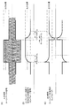
図16は、本発明の実施形態に係る再生装置に適用し得るコンプレッサー回路が有する動特性の一例を示す図である。図16を参照しながら、本発明の実施形態に係る再生装置100に適用し得るコンプレッサー回路160内の非線形増幅部163が有する動特性の一例について説明する。
[1-16. Example of dynamic characteristics of compressor circuit]
FIG. 16 is a diagram illustrating an example of dynamic characteristics of a compressor circuit that can be applied to the playback device according to the embodiment of the present invention. With reference to FIG. 16, an example of the dynamic characteristics of the nonlinear amplifying unit 163 in the
一般的に、コンプレッサーは聴感上自然な音声振幅圧縮を実現するため、時間的に増幅率の変動する動特性を有している。図16(A)に示した入力信号は、トーンバースト信号に相当する。また、図16(B)に示した信号は、コンプレッサーが生成したエンベロープ信号に相当する。コンプレッサー回路160内の非線形増幅部163は、図16(A)に示した入力信号に基づいて図16(B)に示したエンベロープ信号を生成することができる。エンベロープ信号の生成については、図17を参照しながら後に詳細に説明する。
In general, a compressor has dynamic characteristics in which an amplification factor fluctuates with time in order to realize sound amplitude compression that is natural in terms of hearing. The input signal shown in FIG. 16A corresponds to a tone burst signal. Further, the signal shown in FIG. 16B corresponds to an envelope signal generated by the compressor. The nonlinear amplifier 163 in the
非線形増幅部163は、図16(B)に示したエンベロープ信号の大きさと出力目標レベルとの比率から、増幅ゲイン率を求める。具体的には、非線形増幅部163は、出力目標レベルをエンベロープ信号の大きさで除算して増幅ゲイン率とする。非線形増幅部163は、この増幅ゲイン率を、時々刻々、図16(A)に示した入力信号に乗算することで、図16(C)に示した出力信号を得ることができる。図16(C)に示した出力信号は、トーンバースト信号のエンベロープを表している。 The nonlinear amplification unit 163 obtains an amplification gain rate from the ratio between the envelope signal magnitude and the output target level shown in FIG. Specifically, the nonlinear amplifying unit 163 divides the output target level by the magnitude of the envelope signal to obtain an amplification gain factor. The nonlinear amplifying unit 163 can obtain the output signal shown in FIG. 16C by multiplying the input gain shown in FIG. 16A by this amplification gain factor every moment. The output signal shown in FIG. 16C represents the envelope of the tone burst signal.
[1−17.コンプレッサー回路における制御信号の生成手法の一例]
図17は、本発明の実施形態に係る再生装置100に適用し得るコンプレッサー回路160内の非線形増幅部163における制御信号(エンベロープ信号)の生成手法の一例を示す図である。図17を参照しながら、本発明の実施形態に係る再生装置100に適用し得るコンプレッサー回路160における制御信号(エンベロープ信号)の生成手法の一例について説明する。
[1-17. Example of control signal generation method in compressor circuit]
FIG. 17 is a diagram illustrating an example of a control signal (envelope signal) generation method in the non-linear amplification unit 163 in the
非線形増幅部163は、図16(A)に示した入力信号に対して絶対値をとり、時定数を持たせる。時定数には3種類あり、立ち上がり率を表すアタックタイム、ピークを保持するホールドタイム、立ち下がり率を表すリリースタイムである。非線形増幅部163は、これらのパラメータを変えることで、コンプレッサー回路160内の非線形増幅部163の挙動を変えることができる。具体的には、非線形増幅部163は、これらのパラメータを変えることでコンプレッサー回路160に音響データを通して得られる音声の音色が変化する。一般的には、聴感上において適切な値をパラメータの固定値として設定しておく。
The nonlinear amplifier 163 takes an absolute value for the input signal shown in FIG. 16A and gives a time constant. There are three types of time constants: attack time indicating the rising rate, hold time for holding the peak, and release time indicating the falling rate. The nonlinear amplifying unit 163 can change the behavior of the nonlinear amplifying unit 163 in the
[1−18.音響データの音量補正の処理の流れの詳細]
図18は、本発明の実施形態に係る再生装置による音響データの音量補正の処理の流れの詳細を示すフローチャートである。図18を参照しながら、本発明の実施形態に係る再生装置100による音響データの音量補正の処理の流れの詳細について説明する。なお、図18に示した処理は、上記した2パス目の処理に相当する。
[1-18. Details of the flow of sound data volume correction]
FIG. 18 is a flowchart showing details of the processing flow of sound data volume correction by the playback apparatus according to the embodiment of the present invention. With reference to FIG. 18, the details of the flow of the sound data volume correction processing by the
図18に示すように、再生装置100の属性情報取得部140は、受信部110を介して再生対象音響データのRMS値を取得する(ステップS303)。パラメータ算出部150は、属性情報取得部140により取得されたRMS値とあらかじめ定められたRMS基準値との大小を比較する(ステップS302)。RMS基準値は、複数の音響データのRMS値の分布に基づいて決定されるものであり、その決定手法については後に詳細に説明する。
As illustrated in FIG. 18, the attribute
パラメータ算出部150は、RMS値が基準値より小さい場合は、音量増幅(ゲイン増幅)を行うためのパラメータを算出し、RMS値より大きい場合は、音量減衰(ゲイン減衰)を行うためのパラメータを算出する。RMS値が基準値と同じ場合は、音量補正を行わない(スルー出力する)ようにするためのパラメータを算出する。パラメータ算出部150は、例えば、コンプレッサー回路160内の線形増幅部161に設定される線形補正用パラメータ(例えば、増幅率Sgain)、およびコンプレッサー回路160内の非線形増幅部163に設定される非線形補正用パラメータ(例えば、増幅率Dgain)を算出することができる。コンプレッサー回路160は、パラメータ算出部150により算出されたパラメータに基づいて、音量補正を行う。
The
[1−19.パラメータ算出部によるパラメータ(音量増幅時)の算出例]
図19は、本発明の実施形態に係る再生装置100に適用し得るパラメータ算出部150によるパラメータの算出例(音響データの音量を増幅する場合)を示す図である。図19を参照しながら、本発明の実施形態に係る再生装置100に適用し得るパラメータ算出部150によるパラメータの算出例(音響データの音量を増幅する場合)について説明する。
[1-19. Example of parameter (during volume amplification) calculation by parameter calculation unit]
FIG. 19 is a diagram illustrating a parameter calculation example (when the volume of acoustic data is amplified) by the
図19に示すように、音響データの音量を増幅する場合、パラメータ算出部150は、再生対称音響データの音量が全体で(RMS基準値/RMS値)倍に増幅するよう、線形増幅部161に設定される増幅率Sgain(線形補正用パラメータの一例)および非線形増幅部163に設定される増幅率Dgain(非線形補正用パラメータの一例)を算出する。
As shown in FIG. 19, when amplifying the volume of the acoustic data, the
まず、線形増幅部161に設定される増幅率Sgainの算出方法について述べる。ここでは、再生対象音響データのメタデータの1つであるPeak値を利用する。パラメータ算出部150は、例えば、メタデータの1つであるPeak値と音量上限値(例えば、「32768」)との比率を線形増幅部161に設定される増幅率Sgainとして算出する。パラメータ算出部150により算出された増幅率Sgainは、パラメータ算出部150により線形増幅部161に設定される。線形増幅部161では線形増幅を行い、メタデータの1つであるPeak値を考慮した増幅のため、飽和しないことが保証されている。このため、線形増幅部161における音量増幅に際して音声の歪みは発生しない。但し、線形増幅部161では音量増幅が足りない可能性があり、音量増幅の不足分については非線形増幅部163にて補うことができる。
First, a method for calculating the amplification factor Sgain set in the linear amplification unit 161 will be described. Here, a Peak value, which is one of metadata of reproduction target acoustic data, is used. For example, the
次に、非線形増幅部163に設定される増幅率Dgainの算出方法について述べる。ここでは、再生対象音響データのメタデータの1つであるRMS値を利用する。パラメータ算出部150は、再生対象音響データのRMS値に対するRMS基準値の比率に基づいて増幅率Dgainを算出する。パラメータ算出部150により算出された増幅率Dgainは、パラメータ算出部150により非線形増幅部163に設定される。パラメータ算出部150は、例えば、(RMS基準値/RMS値)/Sgainを増幅率Dgainとして算出する。かかる値が増幅率Dgainとしてパラメータ算出部150により設定されれば、非線形増幅部163における増幅を、増幅率Sgainを考慮して低く抑えられる。すなわち、音声の歪みを低く抑えることができる。増幅率Dgainは、図13に示した静特性における増幅率に相当する。
Next, a method for calculating the amplification factor Dgain set in the nonlinear amplification unit 163 will be described. Here, the RMS value which is one of the metadata of the reproduction target acoustic data is used. The
[1−20.パラメータ算出部によるパラメータ(音量減衰時)の算出例]
図20は、本発明の実施形態に係る再生装置100に適用し得るパラメータ算出部150によるパラメータの算出例(音響データの音量を減衰する場合)を示す図である。図20を参照しながら、本発明の実施形態に係る再生装置100に適用し得るパラメータ算出部150によるパラメータの算出例(音響データの音量を減衰する場合)について説明する。
[1-20. Example of calculating parameters (during volume attenuation) by the parameter calculation unit]
FIG. 20 is a diagram showing a parameter calculation example (when the volume of acoustic data is attenuated) by the
図20に示すように、音響データの音量を減衰する場合、パラメータ算出部150は、再生対象音響データのRMS値に対するRMS基準値の比率を線形増幅部161に設定される増幅率Sgain(線形補正用パラメータの一例)として算出する。パラメータ算出部150により算出された増幅率Sgainは、パラメータ算出部150により線形増幅部161に設定される。
As shown in FIG. 20, when the volume of the acoustic data is attenuated, the
パラメータ算出部150は、「0.0」を増幅率Dgain(非線形補正用パラメータの一例)として算出する。「1.0」を増幅率Tgainとして算出する。パラメータ算出部150により算出された増幅率Dgainおよび増幅率Tgainは、パラメータ算出部150により非線形増幅部163および線形増幅部162に設定される。かかる値がパラメータ算出部150により設定されれば、線形増幅部162により線形減衰を行うため、音声の歪み無く減衰することができる。線形増幅部162はスルー出力を行い、非線形増幅部163は無音を出力し、線形増幅部162および非線形増幅部163から出力された両出力が加算され、最終段の出力信号となる。
The
[1−21.パラメータ算出部によるパラメータ(スルー出力時)の算出例]
図21は、本発明の実施形態に係る再生装置100に適用し得るパラメータ算出部150によるパラメータの算出例(音響データをスルー出力する場合)を示す図である。図21を参照しながら、本発明の実施形態に係る再生装置100に適用し得るパラメータ算出部150によるパラメータの算出例(音響データをスルー出力する場合)について説明する。
[1-21. Example of calculating parameters (through output) by the parameter calculation unit]
FIG. 21 is a diagram showing a parameter calculation example (when acoustic data is output through) by the
図21に示すように、音響データをスルー出力する場合、パラメータ算出部150は、「1.0」を線形増幅部161に設定される増幅率Sgain(線形補正用パラメータの一例)として算出する。また、パラメータ算出部150は、「0.0」を増幅率Dgain(非線形補正用パラメータの一例)として算出する。また、パラメータ算出部150は、「1.0」を増幅率Tgainとして算出する。
As illustrated in FIG. 21, when the acoustic data is output through, the
パラメータ算出部150により算出された増幅率Sgain、増幅率Dgainおよび増幅率Tgainは、パラメータ算出部150により線形増幅部161、非線形増幅部163および線形増幅部162に設定される。かかる値がパラメータ算出部150により設定されれば、非線形増幅部163による処理が行われないため、歪みのない音声を出力することができる。
The amplification factor Sgain, amplification factor Dgain, and amplification factor Tgain calculated by the
次に、パラメータ算出部150において算出に用いられているRMS基準値の求め方について述べる。RMS基準値は、例えば、再生対象音響データのPeak値及びRMS値の統計分布から算出する。
[1−22.音量特性値の一例としてのPeak値の統計分布]
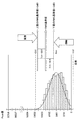
図22は、本発明の実施形態に係る音量特性値の一例としてのPeak値の統計分布について説明するための図である。図22を参照しながら、本発明の実施形態に係る音量特性値の一例としてのPeak値の統計分布について説明する。
Next, how to obtain the RMS reference value used for calculation in the
[1-22. Statistical distribution of Peak value as an example of volume characteristic value]
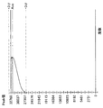
FIG. 22 is a diagram for explaining a statistical distribution of Peak values as an example of a volume characteristic value according to the embodiment of the present invention. A statistical distribution of Peak values as an example of a volume characteristic value according to the embodiment of the present invention will be described with reference to FIG.
図22は、一般的な楽曲(音響データの例)群のPeak値の統計分布(ヒストグラム)を示している。多くの楽曲のPeak値は音量の上限値である32768の付近となっているが、図22に示されたヒストグラムを参照する限りは、Peak値が音量の上限値付近にない曲も多く存在しているので、そのような楽曲に対しては、図19に示したような、線形増幅のための各増幅率の組み合わせを適用することで、非線形増幅による音声の歪みを適切に抑えることができる。本例では、RMS基準値の算出にPeak値の統計分布を直接利用していないが、例えば、Peak値の統計分布の平均値と後述するRMS値の統計分布の平均値との差分とから、最適な増幅率となるよう非線形増幅部163が有する静特性と動特性を変更してもよい。 FIG. 22 shows a statistical distribution (histogram) of Peak values of a general musical piece (example of acoustic data) group. The Peak value of many songs is in the vicinity of 32768 which is the upper limit value of the volume, but as long as the histogram shown in FIG. 22 is referred to, there are many songs whose Peak value is not near the upper limit value of the volume. Therefore, by applying a combination of amplification factors for linear amplification as shown in FIG. 19 to such a musical piece, it is possible to appropriately suppress the distortion of sound due to nonlinear amplification. . In this example, the statistical distribution of the Peak value is not directly used to calculate the RMS reference value. For example, from the difference between the average value of the statistical distribution of Peak values and the average value of the statistical distribution of RMS values described later, The static characteristics and dynamic characteristics of the nonlinear amplification unit 163 may be changed so as to obtain an optimum amplification factor.
[1−23.音量特性値の一例としてのRMS値の統計分布]
図23は、本発明の実施形態に係る音量特性値の一例としてのRMS値の統計分布について説明するための図である。図23を参照しながら、本発明の実施形態に係る音量特性値の一例としてのRMS値の統計分布について説明する。
[1-23. Statistical distribution of RMS value as an example of volume characteristic value]
FIG. 23 is a diagram for explaining a statistical distribution of RMS values as an example of the volume characteristic value according to the embodiment of the present invention. With reference to FIG. 23, the statistical distribution of the RMS value as an example of the volume characteristic value according to the embodiment of the present invention will be described.
図23は、一般的な楽曲(音響データの例)群のRMS値の統計分布(ヒストグラム)を示している。図23を参照すると、RMS値の平均値を中心にほぼ正規分布で広範囲に広がっているのがわかる。数十dBの音量差で、さまざまな楽曲が分布していることがわかる。リスナーが再生しようとしている楽曲群に相当する音楽ライブラリは既知であるため、それらの楽曲群の統計分布を予め求めておくことは可能である。ネットワークを介したストリーミング再生のユースケースに関しても同様である。本発明の実施形態においては、再生する楽曲群の統計分布を、図22、図23などに示したようにあらかじめ計算して求めておくことができる。 FIG. 23 shows a statistical distribution (histogram) of RMS values of a general music piece (example of acoustic data). Referring to FIG. 23, it can be seen that the distribution is wide in a substantially normal distribution centering on the average value of the RMS values. It can be seen that various musical pieces are distributed with a volume difference of several tens of dB. Since the music library corresponding to the music group that the listener is going to reproduce is known, it is possible to obtain the statistical distribution of those music groups in advance. The same applies to the use case of streaming playback via the network. In the embodiment of the present invention, the statistical distribution of the music group to be reproduced can be calculated in advance as shown in FIGS.
[1−24.RMS基準値の決定手法の一例]
図24は、本発明の実施形態に係る再生装置100による音響データの音量補正の処理に使用され得るRMS基準値の決定手法の一例について説明するための図である。図24を参照しながら、本発明の実施形態に係る再生装置100による音響データの音量補正の処理に使用され得るRMS基準値の決定手法の一例について説明する。
[1-24. Example of RMS reference value determination method]
FIG. 24 is a diagram for explaining an example of a method for determining an RMS reference value that can be used for the sound data volume correction processing by the
図24に示すように、解析部230は、統計分布からRMS値の平均値を求めることができる。解析部230は、RMS値の平均値をRMS基準値としてもよいが、図24に示した例では、RMS値の平均値+1.5シグマ(シグマは標準偏差)をRMS基準値としている。また、解析部230は、RMS値の平均値+3シグマ−数dB(例えば、6dB)をRMS基準値としてもよい。解析部230は、RMS値の平均値をRMS基準値としない理由は、より多くの楽曲に対して、音量補正をゲイン増幅モードで動作させるためであり、量子化ビット数16ビットを有効に利用したS/Nの良い音にすることができる。
As shown in FIG. 24, the
ノーマライザーを3つの動作モード(ゲイン増幅、ゲイン減衰、スルー出力)のいずれにより動作させるのが好ましいかはユーザに嗜好によるので、このRMS基準値の決め方は一通りではなく、ユーザが統計分布のRMS平均値を基準に好きな音量レベルに決めてよい。 It is up to the user to decide which of the three operating modes (gain amplification, gain attenuation, and through output) is preferred for operation, so there is no one way to determine this RMS reference value. You may decide on a favorite volume level on the basis of the RMS average value.
[1−25.RMS基準値の決定手法の他の一例]
図25は、本発明の実施形態に係る再生装置100による音響データの音量補正の処理に使用され得るRMS基準値の決定手法の他の一例について説明するための図である。図25を参照しながら、本発明の実施形態に係る再生装置100による音響データの音量補正の処理に使用され得るRMS基準値の決定手法の他の一例について説明するための図である。
パラ
[1-25. Another example of RMS reference value determination method]
FIG. 25 is a diagram for explaining another example of the RMS reference value determination method that can be used in the sound data volume correction processing by the
Para
図24に示した例では、RMS基準値を一つとしたが、図25に示した例では、RMS基準値の上限値と下限値の2つを設けている。このとき、パラメータ算出部150は、RMS基準値よりも小さい下側基準値(下限のRMS基準値)より再生対象音響データのRMS値が小さい場合に再生対象音響データの音量を増幅するためのパラメータを算出する。また、パラメータ算出部150は、RMS基準値よりも大きい上側基準値(上限のRMS基準値)より再生対象音響データのRMS値が大きい場合に再生対象音響データの音量を減衰するためのパラメータを算出する。パラメータ算出部150は、下限のRMS基準値と上限のRMS基準値との間に再生対象音響データのRMS値が含まれる場合、再生対象音響データをスルー出力させるためのパラメータを算出する。
In the example shown in FIG. 24, there is one RMS reference value, but in the example shown in FIG. 25, two upper and lower limits of the RMS reference value are provided. At this time, the
RMS基準値と下側基準値との差分およびRMS基準値と上側基準値との差分についは、特に限定されるものではなく、例えば、3dBとすることができる。すなわち、RMS基準値+3dBを上限のRMS基準値とし、RMS基準値−3dBレベルを下限のRMS基準値とすることができる。コンプレッサー回路160は、上限のRMS基準値より大きいRMS値を持つ楽曲に対してはゲイン減衰の音量補正動作を行い、下限のRMS基準値より小さいRMS値を持つ楽曲に対してはゲイン増幅の音量補正動作を行うことができる。上限のRMS基準値と下側のRMS基準値との間のRMS値を持つ楽曲に対しては何もせずに、楽曲をスルー出力する。スルー出力することで、再生対象音響データに必要以上の音量制御処理をする必要がなくなり、音質の劣化を最小限にすることができる。これらの動作モードの設定に関しても、ユーザ側で統計分布のRMS平均値を基準に自由に決めることができる。
The difference between the RMS reference value and the lower reference value and the difference between the RMS reference value and the upper reference value are not particularly limited, and may be 3 dB, for example. That is, the RMS reference value +3 dB can be set as the upper limit RMS reference value, and the RMS reference value −3 dB level can be set as the lower limit RMS reference value. The
<2.使用例>
以上に説明した本発明の実施形態に係る再生システム10の使用例と一般的な再生システムの使用例とについて説明する。以下に示すように、一般的な再生システムの使用例についてシナリオ1、2に記載し、本発明の実施形態に係る再生システム10の使用例についてシナリオ例3に記載する。
<2. Example of use>
A usage example of the
シナリオ例1)
Aさんはこれまでに購入したCDが100枚くらいあり、これらの楽曲は全てPCなどにリッピングして保存している。楽曲数として1000曲くらいがPCに保存されている。その中にはクラシックの曲やロックの曲が混じっている。AさんはPC上の音楽ファイルを専用のソフトウェアを使ってランダム再生してみた。
Example scenario 1)
Mr. A has about 100 CDs purchased so far, and all these songs are ripped and saved on a PC. About 1000 songs are stored on the PC. It contains a mix of classic and rock songs. Mr. A tried to play music files on the PC randomly using dedicated software.
1曲目はロックが再生された。音量が大きめだったので音量ボリュームを10段階中3にした。次に2曲目にクラシックが再生された。音量がとても小さく感じたので、Aさんは音量ボリュームを3から7に上げた。ところがこのクラシックの曲は後半にとても盛り上がり、うるさく感じられてきた。そこでAさんはボリュームを5に下げた。3曲目は再び、別のロックの曲が再生された、音量がすごく大きく感じられたので、ボリュームを5から3に下げた。Aさんは音量調整をとても煩わしく感じた。 The first song was played with rock. Since the volume was large, the volume volume was set to 3 out of 10 levels. Next, the classic was played on the second song. Mr. A raised the volume from 3 to 7 because the volume felt very low. However, this classical song was very exciting in the second half and felt noisy. So A lowered the volume to 5. For the third song, another rock song was played again, and the volume felt very loud, so the volume was lowered from 5 to 3. Mr. A felt the volume adjustment very annoying.
シナリオ例2)
Aさんは、既存の「ダイナミック型」のノーマライザー処理をONにした。AさんはPC上の音楽ファイルを専用のソフトウェアを使ってランダム再生してみた。1曲目はロックが再生された。音量が大きめだったので音量ボリュームを10段階中3にした。次に2曲目にクラシックが再生された。音量はロックの曲とそんなに差を感じなかったので3のまま再生した。ところがクラシックの曲のフルートやピアノの音が原曲と比べて、なぜか歪みっぽく感じられた。
Scenario example 2)
Mr. A turned on the existing “dynamic” normalizer. Mr. A tried to play music files on the PC randomly using dedicated software. The first song was played with rock. Since the volume was large, the volume volume was set to 3 out of 10 levels. Next, the classic was played on the second song. Since the volume did not feel so much different from that of the rock song, I played it as 3. However, the flute and piano sounds of classical music seemed to be distorted for some reason compared to the original music.
そして、このクラシック曲は前半が静かで後半がすごく盛り上がるはずなのに、前半からフルートとピアノの音量がすごく上がり過ぎているのが気になった。前半の音量感の勢いのまま後半の盛り上がり部分に突入したので、後半のドラマチックな盛り上がり方を感じ取ることができなかった。3曲目は再び、別のロックの曲が再生された。音量調整は全体を通して3のままで変える必要がなかったが、クラシックの曲の音量の不自然さや歪みによる音質の劣化が気になった。 And this classic song was quiet in the first half and should be very exciting in the second half, but I was worried that the volume of the flute and piano has increased too much from the first half. As we entered the excitement of the latter half with the momentum of the first half, we could not feel the dramatic excitement of the latter half. The third song was played again with another rock song. The volume adjustment did not need to be changed to 3 throughout, but I was worried about the deterioration of the sound quality due to unnaturalness and distortion of classical songs.
シナリオ例3)
Aさんは本発明の実施形態に係る再生システム10の音量補正機能をONにした。AさんはPC上の音楽ファイルを専用のソフトウェアを使ってランダム再生してみた。1曲目はロックが再生された。音量が大きめだったので音量ボリュームを10段階中3にした。次に2曲目にクラシックが再生された。静かな感じのフルートとピアノの演奏から始まったが、音量を上げようと思う程ではなかった。むしろ、静寂の中のフルートとピアノの演奏が心地良かった。音も透き通ったようなきれいな音色が響いていた。後半は打楽器を含む大人数でのオーケストラの演奏が始まり、すごく盛り上がり感を感じとることができた。この場合でも音量は3のままで最適な音量感を感じとることができた。
Example scenario 3)
Mr. A turned on the volume correction function of the
クラシック曲の再生が終わり、3曲目は再び、別のロックの曲が再生された。クラシックの後にロック調の気持の良いドラムやギター音が再生されたが、音量感はちょうど良かった。音量調整は全体を通して3のままで変える必要がなかった。全体を通して、クラシックのやさしい音色とロックの激しい音色の対比が気持ちよかった。音量感は全体を通して3でちょうど良かった。 The classic song has finished playing, and the third song again has another rock song. After classical music, rock-like drums and guitar sounds were played, but the volume was just right. The volume adjustment remained at 3 throughout and did not need to be changed. Overall, the contrast between the gentle tone of the classic and the intense tone of the rock was pleasant. The feeling of volume was just 3 throughout.
<3.変形例>
以上、添付図面を参照しながら本発明の好適な実施形態について詳細に説明したが、本発明はかかる例に限定されない。本発明の属する技術の分野における通常の知識を有する者であれば、特許請求の範囲に記載された技術的思想の範疇内において、各種の変更例または修正例に想到し得ることは明らかであり、これらについても、当然に本発明の技術的範囲に属するものと了解される。
<3. Modification>
The preferred embodiments of the present invention have been described in detail above with reference to the accompanying drawings, but the present invention is not limited to such examples. It is obvious that a person having ordinary knowledge in the technical field to which the present invention pertains can come up with various changes or modifications within the scope of the technical idea described in the claims. Of course, it is understood that these also belong to the technical scope of the present invention.
例えば、上記実施形態では、提供装置200により保持されている楽曲に対してRMS基準値を算出するための統計処理を行うこととしたが、本発明はかかる例に限定されない。例えば、RMS基準値を楽曲のジャンルごとに行うようにしてもよい。例えば、クラシック曲の楽曲群のRMS基準値とロック曲の楽曲群のRMS基準値とを別個に算出し、再生装置100による音量補正に使用することも可能である。また、各ユーザのプレイリストごとに算出してもよい。また、上記実施形態では、RMS基準値を算出するための統計処理を提供装置200が行うこととしたが、再生装置100が行うこととすることもできる。
For example, in the above-described embodiment, the statistical processing for calculating the RMS reference value is performed on the music held by the providing
<4.まとめ>
本実施形態によれば、元の音響データの音量変化に比較的近い音量変化を維持しつつ各音響データ間の音量の違いを低減させ、音量増幅による音声の歪みを低減させながら音響データを再生することが可能である。
<4. Summary>
According to this embodiment, while maintaining the volume change relatively close to the volume change of the original acoustic data, the difference in volume between each acoustic data is reduced, and the acoustic data is reproduced while reducing the distortion of the sound due to the volume amplification. Is possible.
10 再生システム
100 再生装置
110 受信部
120 映像音響データ取得部
130 映像音響データデコード回路(再生部)
140 属性情報取得部
150 パラメータ算出部
160 コンプレッサー回路(音量補正部)
161 線形増幅部
162 線形増幅部
163 非線形増幅部
170 ミキサー装置
180 記憶部
200 提供装置
210 記憶部
220 取得部
230 解析部
240 送信部
300 出力装置
310 音声出力部
320 画像出力部
DESCRIPTION OF
140 Attribute
161 Linear Amplification Unit 162 Linear Amplification Unit 163
Claims (11)
前記再生部により再生された前記音響データの音量を、複数の音響データの各々の音量特性値と前記音響データの音量特性値との関係に基づいて補正する音量補正部と、
を備える、再生装置。 A playback unit for playing back acoustic data;
A volume correction unit that corrects the volume of the acoustic data reproduced by the reproduction unit based on the relationship between the volume characteristic value of each of the plurality of acoustic data and the volume characteristic value of the acoustic data;
A playback device comprising:
前記複数の音響データの各々の音量特性値と前記音響データの音量特性値との関係に基づいて音量補正のためのパラメータを算出するパラメータ算出部をさらに備え、
前記音量補正部は、
前記パラメータ算出部により算出されたパラメータに従って前記音響データの音量を補正する、
請求項1に記載の再生装置。 The playback device
A parameter calculation unit that calculates a parameter for volume correction based on the relationship between the volume characteristic value of each of the plurality of acoustic data and the volume characteristic value of the acoustic data;
The volume correction unit is
Correcting the volume of the acoustic data according to the parameter calculated by the parameter calculation unit;
The playback apparatus according to claim 1.
前記音響データの音量平均値を示し、
前記パラメータ算出部は、
前記複数の音響データの前記音量平均値の分布に基づいて決定される基準平均値より前記音響データの前記音量平均値が小さい場合に前記音響データの音量を増幅するためのパラメータを算出し、
前記基準平均値よりも前記音響データの前記音量平均値が大きい場合に前記音響データの音量を減衰するためのパラメータを算出する、
請求項2に記載の再生装置。 The volume characteristic value is
Indicates the volume average value of the acoustic data,
The parameter calculation unit
Calculating a parameter for amplifying the volume of the acoustic data when the volume average value of the acoustic data is smaller than a reference average value determined based on a distribution of the volume average values of the plurality of acoustic data;
Calculating a parameter for attenuating the volume of the acoustic data when the volume average value of the acoustic data is larger than the reference average value;
The reproducing apparatus according to claim 2.
非線形補正部および第1の線形補正部を有し、
前記パラメータ算出部は、
前記第1の線形補正部に設定される線形補正用パラメータ、および前記非線形補正部に設定される非線形補正用パラメータを算出する、
請求項3に記載の再生装置。 The volume correction unit is
A non-linear correction unit and a first linear correction unit;
The parameter calculation unit
Calculating a linear correction parameter set in the first linear correction unit and a nonlinear correction parameter set in the nonlinear correction unit;
The playback apparatus according to claim 3.
前記基準平均値より前記音響データの前記音量平均値が小さい場合、前記音響データの音量ピーク値に対する音量上限値の比率を前記線形補正用パラメータとして算出し、前記音響データの前記音量平均値に対する前記基準平均値の比率に基づいて前記非線形補正用パラメータを算出する、
請求項4に記載の再生装置。 The parameter calculation unit
When the volume average value of the acoustic data is smaller than the reference average value, the ratio of the volume upper limit value to the volume peak value of the acoustic data is calculated as the linear correction parameter, and the volume level relative to the volume average value of the acoustic data is calculated. Calculating the nonlinear correction parameter based on the ratio of the reference average value;
The reproducing apparatus according to claim 4.
前記基準平均値より前記音響データの前記音量平均値が大きい場合、前記音響データの前記音量平均値に対する前記基準平均値の比率を前記線形補正用パラメータとして算出する、
請求項5に記載の再生装置。 The parameter calculation unit
When the volume average value of the acoustic data is larger than the reference average value, a ratio of the reference average value to the volume average value of the acoustic data is calculated as the linear correction parameter.
The playback apparatus according to claim 5.
前記基準平均値よりも小さい下側基準値より前記音響データの前記音量平均値が小さい場合に前記音響データの音量を増幅するためのパラメータを算出し、
前記基準平均値よりも大きい上側基準値より前記音響データの前記音量平均値が大きい場合に前記音響データの音量を減衰するためのパラメータを算出し、
前記下側基準値と前記上側基準値との間に前記音響データの前記音量平均値が含まれる場合、前記音響データをスルー出力させるためのパラメータを前記音量補正部に設定する、
請求項6に記載の再生装置。 The parameter calculation unit
Calculating a parameter for amplifying the volume of the acoustic data when the volume average value of the acoustic data is smaller than a lower reference value smaller than the reference average value;
Calculating a parameter for attenuating the volume of the acoustic data when the volume average value of the acoustic data is larger than the upper reference value larger than the reference average value;
When the volume average value of the acoustic data is included between the lower reference value and the upper reference value, a parameter for causing the acoustic data to be output through is set in the volume correction unit.
The playback apparatus according to claim 6.
前記第1の線形補正部の後段に前記非線形補正部と並列に接続される第2の線形補正部を有し、
前記パラメータ算出部は、
前記音響データをスルー出力させるためのパラメータとして、前記第1の線形補正部および前記第2の線形補正部に増幅率1を設定し、前記非線形補正用パラメータとして増幅率0を設定する、
請求項7に記載の再生装置。 The volume correction unit is
A second linear correction unit connected in parallel with the non-linear correction unit after the first linear correction unit;
The parameter calculation unit
As a parameter for through-outputting the acoustic data, an amplification factor of 1 is set in the first linear correction unit and the second linear correction unit, and an amplification factor of 0 is set as the nonlinear correction parameter.
The playback device according to claim 7.
再生された前記音響データの音量を、複数の音響データの各々の音量特性値と前記音響データの音量特性値の関係とに基づいて補正するステップと;
を含む、再生方法。 Playing back acoustic data;
Correcting the volume of the reproduced acoustic data based on the relationship between the volume characteristic value of each of the plurality of acoustic data and the volume characteristic value of the acoustic data;
Including a playback method.
前記音響データおよび前記複数の音響データの各々の音量特性値を取得する取得部と、
前記音響データを解析するとともに前記複数の音響データの各々の音量特性値の分布を解析する解析部と、
音響データを再生する再生装置に、前記音響データ、および前記解析部による解析結果を送信する送信部と、
を備える、提供装置。 A storage unit that stores sound volume characteristic values of each of the acoustic data and the plurality of acoustic data;
An acquisition unit for acquiring a volume characteristic value of each of the acoustic data and the plurality of acoustic data;
Analyzing the acoustic data and analyzing the distribution of volume characteristic values of each of the plurality of acoustic data;
A transmission unit that transmits the acoustic data and the analysis result by the analysis unit to a reproduction device that reproduces the acoustic data;
A providing device comprising:
前記音響データおよび前記複数の音響データの各々の音量特性値を取得する取得部、
前記音響データを解析するとともに前記複数の音響データの各々の音量特性値の分布を解析する解析部、および
前記解析部による解析結果を送信する送信部、
を有する提供装置と;
前記提供装置から、前記音響データ、および前記解析結果を受信する受信部、
前記音響データを再生する再生部、および、
前記再生部により再生された前記音響データの音量を前記解析結果に基づいて補正する音量補正部、
を有する再生装置と、
を備える、再生システム。
A storage unit for storing the volume characteristic value of each of the acoustic data and the plurality of acoustic data;
An acquisition unit for acquiring a volume characteristic value of each of the acoustic data and the plurality of acoustic data;
An analysis unit that analyzes the acoustic data and analyzes a distribution of volume characteristic values of each of the plurality of acoustic data; and a transmission unit that transmits an analysis result by the analysis unit;
A providing device comprising:
A receiving unit for receiving the acoustic data and the analysis result from the providing device;
A playback unit for playing back the acoustic data; and
A volume correction unit that corrects the volume of the acoustic data reproduced by the reproduction unit based on the analysis result;
A playback device having
A reproduction system comprising:
Priority Applications (2)
| Application Number | Priority Date | Filing Date | Title |
|---|---|---|---|
| JP2010250714A JP5585401B2 (en) | 2010-11-09 | 2010-11-09 | REPRODUCTION DEVICE, REPRODUCTION METHOD, PROVIDING DEVICE, AND REPRODUCTION SYSTEM |
| US13/287,000 US9148104B2 (en) | 2010-11-09 | 2011-11-01 | Reproduction apparatus, reproduction method, provision apparatus, and reproduction system |
Applications Claiming Priority (1)
| Application Number | Priority Date | Filing Date | Title |
|---|---|---|---|
| JP2010250714A JP5585401B2 (en) | 2010-11-09 | 2010-11-09 | REPRODUCTION DEVICE, REPRODUCTION METHOD, PROVIDING DEVICE, AND REPRODUCTION SYSTEM |
Publications (2)
| Publication Number | Publication Date |
|---|---|
| JP2012104992A true JP2012104992A (en) | 2012-05-31 |
| JP5585401B2 JP5585401B2 (en) | 2014-09-10 |
Family
ID=46019643
Family Applications (1)
| Application Number | Title | Priority Date | Filing Date |
|---|---|---|---|
| JP2010250714A Expired - Fee Related JP5585401B2 (en) | 2010-11-09 | 2010-11-09 | REPRODUCTION DEVICE, REPRODUCTION METHOD, PROVIDING DEVICE, AND REPRODUCTION SYSTEM |
Country Status (2)
| Country | Link |
|---|---|
| US (1) | US9148104B2 (en) |
| JP (1) | JP5585401B2 (en) |
Cited By (6)
| Publication number | Priority date | Publication date | Assignee | Title |
|---|---|---|---|---|
| JP2014078298A (en) * | 2012-10-10 | 2014-05-01 | Teac Corp | Sound recording device |
| JP2014078297A (en) * | 2012-10-10 | 2014-05-01 | Teac Corp | Sound recording device |
| WO2019181778A1 (en) * | 2018-03-22 | 2019-09-26 | ヤマハ株式会社 | Method and device for displaying dynamic characteristic of dynamics processor |
| WO2019181781A1 (en) * | 2018-03-23 | 2019-09-26 | ヤマハ株式会社 | Dynamics processing method and dynamics processing device |
| JP2020067531A (en) * | 2018-10-23 | 2020-04-30 | 株式会社コーエーテクモゲームス | Program, information processing method, and information processing device |
| JP2021510038A (en) * | 2018-01-07 | 2021-04-08 | グレースノート インコーポレイテッド | Methods and devices for volume control |
Families Citing this family (4)
| Publication number | Priority date | Publication date | Assignee | Title |
|---|---|---|---|---|
| US9729118B2 (en) * | 2015-07-24 | 2017-08-08 | Sonos, Inc. | Loudness matching |
| US10057681B2 (en) | 2016-08-01 | 2018-08-21 | Bose Corporation | Entertainment audio processing |
| US10331400B1 (en) * | 2018-02-22 | 2019-06-25 | Cirrus Logic, Inc. | Methods and apparatus for soft clipping |
| WO2021085242A1 (en) * | 2019-10-30 | 2021-05-06 | ソニー株式会社 | Information processing device, and command processing method |
Citations (4)
| Publication number | Priority date | Publication date | Assignee | Title |
|---|---|---|---|---|
| JPH11352967A (en) * | 1998-06-11 | 1999-12-24 | Casio Comput Co Ltd | Sound effect adder |
| JP2007003845A (en) * | 2005-06-24 | 2007-01-11 | Seiko Epson Corp | Reproduction information generating device and speech reproducing device |
| JP2008065904A (en) * | 2006-09-07 | 2008-03-21 | Sony Corp | Reproducing device, method, and program |
| JP2008521028A (en) * | 2004-11-16 | 2008-06-19 | ソニー エリクソン モバイル コミュニケーションズ, エービー | How to normalize recording volume |
Family Cites Families (1)
| Publication number | Priority date | Publication date | Assignee | Title |
|---|---|---|---|---|
| KR100724836B1 (en) * | 2003-08-25 | 2007-06-04 | 엘지전자 주식회사 | Apparatus and method for controlling audio output level in digital audio device |
-
2010
- 2010-11-09 JP JP2010250714A patent/JP5585401B2/en not_active Expired - Fee Related
-
2011
- 2011-11-01 US US13/287,000 patent/US9148104B2/en not_active Expired - Fee Related
Patent Citations (4)
| Publication number | Priority date | Publication date | Assignee | Title |
|---|---|---|---|---|
| JPH11352967A (en) * | 1998-06-11 | 1999-12-24 | Casio Comput Co Ltd | Sound effect adder |
| JP2008521028A (en) * | 2004-11-16 | 2008-06-19 | ソニー エリクソン モバイル コミュニケーションズ, エービー | How to normalize recording volume |
| JP2007003845A (en) * | 2005-06-24 | 2007-01-11 | Seiko Epson Corp | Reproduction information generating device and speech reproducing device |
| JP2008065904A (en) * | 2006-09-07 | 2008-03-21 | Sony Corp | Reproducing device, method, and program |
Cited By (14)
| Publication number | Priority date | Publication date | Assignee | Title |
|---|---|---|---|---|
| JP2014078297A (en) * | 2012-10-10 | 2014-05-01 | Teac Corp | Sound recording device |
| US9666196B2 (en) | 2012-10-10 | 2017-05-30 | Teac Corporation | Recording apparatus with mastering function |
| JP2014078298A (en) * | 2012-10-10 | 2014-05-01 | Teac Corp | Sound recording device |
| JP2021510038A (en) * | 2018-01-07 | 2021-04-08 | グレースノート インコーポレイテッド | Methods and devices for volume control |
| US11824507B2 (en) | 2018-01-07 | 2023-11-21 | Gracenote, Inc. | Methods and apparatus for volume adjustment |
| US11545949B2 (en) | 2018-01-07 | 2023-01-03 | Gracenote, Inc. | Methods and apparatus for volume adjustment |
| JP7071508B2 (en) | 2018-01-07 | 2022-05-19 | グレースノート インコーポレイテッド | Methods for volume control, computer-readable storage media and equipment |
| WO2019181778A1 (en) * | 2018-03-22 | 2019-09-26 | ヤマハ株式会社 | Method and device for displaying dynamic characteristic of dynamics processor |
| US11252507B2 (en) | 2018-03-23 | 2022-02-15 | Yamaha Corporation | Dynamics processing method and dynamics processing device |
| JP7193772B2 (en) | 2018-03-23 | 2022-12-21 | ヤマハ株式会社 | Dynamics processing method |
| JP2019169887A (en) * | 2018-03-23 | 2019-10-03 | ヤマハ株式会社 | Dynamics processing method |
| WO2019181781A1 (en) * | 2018-03-23 | 2019-09-26 | ヤマハ株式会社 | Dynamics processing method and dynamics processing device |
| JP2020067531A (en) * | 2018-10-23 | 2020-04-30 | 株式会社コーエーテクモゲームス | Program, information processing method, and information processing device |
| JP7194559B2 (en) | 2018-10-23 | 2022-12-22 | 株式会社コーエーテクモゲームス | Program, information processing method, and information processing apparatus |
Also Published As
| Publication number | Publication date |
|---|---|
| US20120114127A1 (en) | 2012-05-10 |
| JP5585401B2 (en) | 2014-09-10 |
| US9148104B2 (en) | 2015-09-29 |
Similar Documents
| Publication | Publication Date | Title |
|---|---|---|
| JP5585401B2 (en) | REPRODUCTION DEVICE, REPRODUCTION METHOD, PROVIDING DEVICE, AND REPRODUCTION SYSTEM | |
| KR101310231B1 (en) | Apparatus and method for enhancing bass | |
| JP4668415B2 (en) | Low frequency audio enhancement system | |
| JP5149991B2 (en) | Audio playback device, audio playback method and program | |
| US20110170710A1 (en) | Method and apparatus for adjusting volume | |
| JP2012235310A (en) | Signal processing apparatus and method, program, and data recording medium | |
| JP2009300707A (en) | Information processing device and method, and program | |
| WO2012111043A1 (en) | Signal processing method, signal processing device, reproduction device, and program | |
| JP4706666B2 (en) | Volume control device and computer program | |
| TW201118719A (en) | System and method for modifying an audio signal | |
| JP5062055B2 (en) | Audio signal processing apparatus and method | |
| US20190074805A1 (en) | Transient Detection for Speaker Distortion Reduction | |
| JP2003243952A (en) | Digital audio system, auto volume control factor generating method, auto volume control method, auto volume control factor generating program, auto volume control program, recording medium for recording the auto volume control factor generating program, and recording medium for recording the auto volume control program | |
| JP4527715B2 (en) | Optimizing playback of MIDI files | |
| JP2009031357A (en) | Music piece distribution system, music piece editing device, music piece playback device, music piece storage device, and program | |
| JP4392040B2 (en) | Acoustic signal processing apparatus, acoustic signal processing method, acoustic signal processing program, and computer-readable recording medium | |
| US8195317B2 (en) | Data reproduction apparatus and data reproduction method | |
| JP5598722B2 (en) | Audio reproduction device and reproduction sound adjustment method in audio reproduction device | |
| JP2002109824A (en) | Method for recording digital audio signal and its device | |
| JP2006350132A (en) | Device, method, and program for audio reproduction | |
| Thiele | Some Thoughts on the Dynamiics of Reproduced Sound | |
| KR100698847B1 (en) | Method for audio service of mobile phone | |
| Ciesla | Bits, Sample Rates, and Other Fundamentals of Digital Audio | |
| JP5440677B2 (en) | Music distribution system, music editing apparatus and program | |
| JP2003273678A (en) | Digital audio system, acoustic characteristic control element generating method, acoustic characteristic control method, acoustic characteristic control element generation program, acoustic characteristic control program, recording medium recorded with acoustic characteristic control element generation program, and recording medium recorded with acoustic characteristic control program |
Legal Events
| Date | Code | Title | Description |
|---|---|---|---|
| A621 | Written request for application examination |
Free format text: JAPANESE INTERMEDIATE CODE: A621 Effective date: 20130920 |
|
| A977 | Report on retrieval |
Free format text: JAPANESE INTERMEDIATE CODE: A971007 Effective date: 20140212 |
|
| A131 | Notification of reasons for refusal |
Free format text: JAPANESE INTERMEDIATE CODE: A131 Effective date: 20140218 |
|
| A521 | Written amendment |
Free format text: JAPANESE INTERMEDIATE CODE: A523 Effective date: 20140414 |
|
| TRDD | Decision of grant or rejection written | ||
| A01 | Written decision to grant a patent or to grant a registration (utility model) |
Free format text: JAPANESE INTERMEDIATE CODE: A01 Effective date: 20140624 |
|
| A61 | First payment of annual fees (during grant procedure) |
Free format text: JAPANESE INTERMEDIATE CODE: A61 Effective date: 20140707 |
|
| R151 | Written notification of patent or utility model registration |
Ref document number: 5585401 Country of ref document: JP Free format text: JAPANESE INTERMEDIATE CODE: R151 |
|
| R250 | Receipt of annual fees |
Free format text: JAPANESE INTERMEDIATE CODE: R250 |
|
| R250 | Receipt of annual fees |
Free format text: JAPANESE INTERMEDIATE CODE: R250 |
|
| R250 | Receipt of annual fees |
Free format text: JAPANESE INTERMEDIATE CODE: R250 |
|
| LAPS | Cancellation because of no payment of annual fees |