JP2012103620A - Image development cartridge and process unit - Google Patents
Image development cartridge and process unit Download PDFInfo
- Publication number
- JP2012103620A JP2012103620A JP2010254088A JP2010254088A JP2012103620A JP 2012103620 A JP2012103620 A JP 2012103620A JP 2010254088 A JP2010254088 A JP 2010254088A JP 2010254088 A JP2010254088 A JP 2010254088A JP 2012103620 A JP2012103620 A JP 2012103620A
- Authority
- JP
- Japan
- Prior art keywords
- developing cartridge
- pressed
- posture
- developing
- axial direction
- Prior art date
- Legal status (The legal status is an assumption and is not a legal conclusion. Google has not performed a legal analysis and makes no representation as to the accuracy of the status listed.)
- Granted
Links
- 238000000034 method Methods 0.000 title claims abstract description 9
- 230000008569 process Effects 0.000 title claims abstract description 9
- 238000011161 development Methods 0.000 title abstract description 4
- 238000003825 pressing Methods 0.000 claims abstract description 47
- 108091008695 photoreceptors Proteins 0.000 claims description 5
- 230000036544 posture Effects 0.000 description 53
- 230000000694 effects Effects 0.000 description 11
- 230000009471 action Effects 0.000 description 9
- 238000000926 separation method Methods 0.000 description 5
- 238000005520 cutting process Methods 0.000 description 4
- 230000004048 modification Effects 0.000 description 4
- 238000012986 modification Methods 0.000 description 4
- 238000003860 storage Methods 0.000 description 4
- 238000004519 manufacturing process Methods 0.000 description 2
- 230000007246 mechanism Effects 0.000 description 2
- 230000002093 peripheral effect Effects 0.000 description 2
- 238000012546 transfer Methods 0.000 description 2
- 238000003491 array Methods 0.000 description 1
- 239000003086 colorant Substances 0.000 description 1
- 238000013461 design Methods 0.000 description 1
- 238000006073 displacement reaction Methods 0.000 description 1
- 238000010438 heat treatment Methods 0.000 description 1
- 230000002452 interceptive effect Effects 0.000 description 1
- 230000000149 penetrating effect Effects 0.000 description 1
Images


Classifications
-
- G—PHYSICS
- G03—PHOTOGRAPHY; CINEMATOGRAPHY; ANALOGOUS TECHNIQUES USING WAVES OTHER THAN OPTICAL WAVES; ELECTROGRAPHY; HOLOGRAPHY
- G03G—ELECTROGRAPHY; ELECTROPHOTOGRAPHY; MAGNETOGRAPHY
- G03G21/00—Arrangements not provided for by groups G03G13/00 - G03G19/00, e.g. cleaning, elimination of residual charge
- G03G21/16—Mechanical means for facilitating the maintenance of the apparatus, e.g. modular arrangements
- G03G21/18—Mechanical means for facilitating the maintenance of the apparatus, e.g. modular arrangements using a processing cartridge, whereby the process cartridge comprises at least two image processing means in a single unit
- G03G21/1803—Arrangements or disposition of the complete process cartridge or parts thereof
- G03G21/1817—Arrangements or disposition of the complete process cartridge or parts thereof having a submodular arrangement
- G03G21/1821—Arrangements or disposition of the complete process cartridge or parts thereof having a submodular arrangement means for connecting the different parts of the process cartridge, e.g. attachment, positioning of parts with each other, pressure/distance regulation
-
- G—PHYSICS
- G03—PHOTOGRAPHY; CINEMATOGRAPHY; ANALOGOUS TECHNIQUES USING WAVES OTHER THAN OPTICAL WAVES; ELECTROGRAPHY; HOLOGRAPHY
- G03G—ELECTROGRAPHY; ELECTROPHOTOGRAPHY; MAGNETOGRAPHY
- G03G2221/00—Processes not provided for by group G03G2215/00, e.g. cleaning or residual charge elimination
- G03G2221/16—Mechanical means for facilitating the maintenance of the apparatus, e.g. modular arrangements and complete machine concepts
- G03G2221/1678—Frame structures
- G03G2221/1684—Frame structures using extractable subframes, e.g. on rails or hinges
Abstract
Description
本発明は、現像カートリッジおよびプロセスユニットに関する。 The present invention relates to a developing cartridge and a process unit.
レーザプリンタなどの画像形成装置の一例では、感光体ドラムを保持するドラムカートリッジが本体ケース内に着脱可能に設けられ、そのドラムカートリッジに現像ローラを保持する現像カートリッジが装着される。ドラムカートリッジに現像カートリッジが装着された状態で、それらはプロセスユニットをなす。 In an example of an image forming apparatus such as a laser printer, a drum cartridge that holds a photosensitive drum is detachably provided in a main body case, and a developing cartridge that holds a developing roller is attached to the drum cartridge. With the developing cartridge mounted on the drum cartridge, they form a process unit.
本体ケース内には、現像ローラを感光体ドラムに押圧させるための押圧機構が備えられている。現像カートリッジの側壁には、係合部(被押圧部)が突出して形成されている。押圧機構は、係合部を挟む1対の挟持体と、一方の挟持体を付勢する付勢バネとを備えている。一方の挟持体が付勢バネにより付勢され、その挟持体により係合部が押圧されることにより、現像ローラが感光体ドラムに押圧される。 A pressing mechanism for pressing the developing roller against the photosensitive drum is provided in the main body case. On the side wall of the developing cartridge, an engaging portion (pressed portion) is formed so as to protrude. The pressing mechanism includes a pair of sandwiching bodies that sandwich the engaging portion, and a biasing spring that biases one of the sandwiching bodies. One holding member is urged by the urging spring, and the engaging portion is pressed by the holding member, whereby the developing roller is pressed against the photosensitive drum.
また、現像ローラを感光体ドラムから離間させるために、カムがその周面を他方の挟持体に接触させた状態で設けられている。カムの回転位置によって、他方の挟持体が一方の挟持体側に押圧され、他方の挟持体により係合部が押圧される。これにより、現像カートリッジが付勢バネの付勢力に抗して移動し、現像ローラが感光体ドラムから離間する。 Further, in order to separate the developing roller from the photosensitive drum, a cam is provided in a state where the peripheral surface thereof is in contact with the other holding member. Depending on the rotational position of the cam, the other clamping body is pressed toward one clamping body, and the engaging portion is pressed by the other clamping body. As a result, the developing cartridge moves against the biasing force of the biasing spring, and the developing roller is separated from the photosensitive drum.
現像ローラが回転していないときに、現像ローラが感光体ドラムから離間されることにより、現像ローラまたは感光体ドラムの変形を防止することができる。 When the developing roller is not rotating, the developing roller is separated from the photosensitive drum, whereby deformation of the developing roller or the photosensitive drum can be prevented.
しかしながら、現像カートリッジの側壁には、現像ローラを駆動するためのギヤや現像ローラへの給電のための電極などの部材が配置されているので、係合部が形成される位置は、かなり制約を受ける。 However, since members such as a gear for driving the developing roller and an electrode for supplying power to the developing roller are arranged on the side wall of the developing cartridge, the position where the engaging portion is formed is considerably limited. receive.
本発明の目的は、押圧力が入力される被押圧部の位置の自由度を増すことができる、現像カートリッジおよびプロセスユニットを提供することである。 An object of the present invention is to provide a developing cartridge and a process unit that can increase the degree of freedom of the position of a pressed portion to which a pressing force is input.
前記の目的を達成するため、第1の発明は、感光体および押圧部材を備える感光体ユニットに対して着脱可能な現像カートリッジにおいて、前記感光体に現像剤を供給する現像ローラと、前記現像ローラの軸線方向に対向する1対の側壁を有し、前記現像ローラを回転可能に支持する筐体と、前記筐体の外側で各前記側壁に沿って延びる1対のアーム部および各前記アーム部から前記軸線方向の外側に延びる被押圧部を有し、前記被押圧部が前記押圧部材により押圧される第1姿勢と、前記押圧部材による前記被押圧部の押圧が解除される第2姿勢とに、前記軸線方向に延びる軸線を中心として揺動可能に設けられた揺動部材とを備えることを特徴としている。 To achieve the above object, according to a first aspect of the present invention, there is provided a developing cartridge detachable from a photosensitive unit including a photosensitive member and a pressing member, a developing roller for supplying a developer to the photosensitive member, and the developing roller. A pair of side walls opposed to each other in the axial direction, and a housing that rotatably supports the developing roller, a pair of arm portions that extend along the side walls outside the housing, and the arm portions A first posture in which the pressed portion that extends outward in the axial direction is pressed by the pressing member, and a second posture in which the pressing of the pressed portion by the pressing member is released And a swinging member provided so as to be swingable about an axis extending in the axial direction.
また、第2の発明は、画像形成装置の装置本体に対して所定方向に移動可能なプロセスユニットにおいて、前記所定方向に互いに間隔を空けて並列に配置される複数の感光体および各前記感光体に対応して設けられた複数の押圧部材とを有する感光体ユニットと、各前記感光体に対応して設けられた、請求項1〜9のいずれか一項に記載の複数の現像カートリッジとを備えることを特徴としている。
According to a second aspect of the present invention, in the process unit that is movable in a predetermined direction with respect to the apparatus main body of the image forming apparatus, a plurality of photoconductors arranged in parallel at intervals in the predetermined direction and the photoconductors And a plurality of developing cartridges according to any one of
第1および第2の発明によれば、現像カートリッジは、感光体および押圧部材を備える感光体ユニットに対して着脱可能である。現像カートリッジの筐体には、感光体に現像剤を供給する現像ローラが回転可能に支持されている。筐体は、現像ローラの軸線方向に対向する1対の側壁を備えている。 According to the first and second inventions, the developing cartridge can be attached to and detached from the photoreceptor unit including the photoreceptor and the pressing member. A developing roller for supplying a developer to the photosensitive member is rotatably supported on the housing of the developing cartridge. The housing includes a pair of side walls that face each other in the axial direction of the developing roller.
筐体の外側には、揺動部材が設けられている。揺動部材は、各側壁に沿って延びる1対のアーム部と、各アーム部から軸線方向の外側に延びる被押圧部とを有している。そして、揺動部材は、軸線方向に延びる軸線を中心として、第1姿勢と第2姿勢とに揺動可能に設けられている。揺動部材が第1姿勢をなす状態で、被押圧部が押圧部材により押圧される。揺動部材が第1姿勢から第2姿勢に変位されると、押圧部材による被押圧部の押圧が解除される。 A swing member is provided on the outside of the housing. The swing member has a pair of arm portions extending along each side wall and a pressed portion extending outward in the axial direction from each arm portion. The swing member is provided so as to be swingable between a first posture and a second posture around an axis extending in the axial direction. The pressed portion is pressed by the pressing member while the swinging member is in the first posture. When the swing member is displaced from the first posture to the second posture, the pressing of the pressed portion by the pressing member is released.
被押圧部が筐体とは別部材である揺動部材に設けられているので、被押圧部の位置は、筐体の側壁に配置される他部材の配置による制約を受けない。よって、被押圧部の位置の自由度を増すことができる。 Since the pressed portion is provided on the swinging member that is a separate member from the casing, the position of the pressed portion is not restricted by the arrangement of other members disposed on the side wall of the casing. Therefore, the freedom degree of the position of a to-be-pressed part can be increased.
また、押圧部材による被押圧部の押圧が繰り返されて、たとえ被押圧部が破損しても、揺動部材を新品と交換すれば、現像カートリッジを使用し続けることができる。よって、現像カートリッジを長期間にわたって使用することができる。 Further, even if the pressed portion is repeatedly pressed by the pressing member and the pressed portion is damaged, the developing cartridge can be continuously used by replacing the swing member with a new one. Therefore, the developing cartridge can be used for a long time.
以下では、本発明の実施の形態について、添付図面を参照しつつ詳細に説明する。
1.カラープリンタ
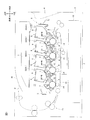
図1に示されるカラープリンタ1は、タンデム型のカラープリンタである。カラープリンタ1は、本体ケーシング2を備えている。本体ケーシング2内には、プロセスユニットの一例としてのドロワユニット3が装着されている。本体ケーシング2の正面には、フロントカバー4が開閉可能に設けられている。そして、ドロワユニット3は、フロントカバー4を開けた状態で、本体ケーシング2内の収容位置(図1に示される位置)と本体ケーシング2外の引出位置(図8Aに示される位置)との間で水平方向に移動させることができる。
Hereinafter, embodiments of the present invention will be described in detail with reference to the accompanying drawings.
1. Color Printer
なお、以下の説明では、カラープリンタ1の正面側を前側とし、その前側からカラープリンタ1の各部(ドロワユニット3を含む。)を見て、上下左右の方向を規定している。
In the following description, the front side of the
ドロワユニット3は、平面視四角枠状のドロワフレーム5を備えている。
The
ドロワフレーム5には、4つの感光体の一例としての感光ドラム6がそれぞれ左右方向に延びる回転軸線を中心に回転可能に保持されている。4つの感光ドラム6は、ブラック、イエロー、マゼンタおよびシアンの各色用として設けられ、前側からブラック、イエロー、マゼンタおよびシアンの順に前後方向に等間隔で並列に配置されている。
The
また、ドロワフレーム5には、4つの帯電器7が保持されている。4つの帯電器7は、それぞれ感光ドラム6に対応して設けられ、その対応する感光ドラム6の後上方に配置されている。帯電器7は、たとえば、ワイヤおよびグリッドを備えるスコロトロン型帯電器である。
The
ドロワユニット3は、ドロワフレーム5に対して着脱可能に構成された4つの現像カートリッジ8を備えている。4つの現像カートリッジ8は、それぞれ感光ドラム6に対応して設けられている。各現像カートリッジ8は、ドロワユニット3が引出位置に引き出された状態でドロワフレーム5の上方から装着され、感光ドラム6の前上方に配置される。なお、ドロワフレーム5から現像カートリッジ8が離脱された状態のドロワユニット3は、感光体ユニットの一例である。
The
各現像カートリッジ8は、筐体9と、筐体9に保持される現像ローラ10とを備えている。現像ローラ10は、左右方向に延びる回転軸線を中心に回転可能に設けられ、その表面(周面)の一部が筐体9から露出している。現像カートリッジ8がドロワフレーム5に装着された状態で、現像ローラ10の表面は、感光ドラム6の表面に前上方から接触する。
Each developing
本体ケーシング2内において、ドロワユニット3の上方には、各色に対応した4本のレーザビームを出射する露光器11が配置されている。
In the
感光ドラム6の回転に伴って、感光ドラム6の表面は、帯電器7からの放電によって一様に帯電された後、露光器11からのレーザビームにより選択的に露光される。この露光によって、感光ドラム6の表面から電荷が選択的に除去され、感光ドラム6の表面に静電潜像が形成される。静電潜像が現像ローラ10に対向すると、現像ローラ10から静電潜像にトナーが供給される。これによって、感光ドラム6の表面にトナー像が担持される。
As the
なお、露光器11に代えて、4つのLEDアレイが各感光ドラム6に対応して設けられてもよい。
Instead of the
本体ケーシング2の底部には、用紙Pを収容する給紙カセット12が配置されている。給紙カセット12に収容されている用紙Pは、各種ローラにより、搬送ベルト13上に搬送される。搬送ベルト13は、4つの感光ドラム6に下方から対向して配置されている。感光ドラム6に対して搬送ベルト13の上側部分を挟んで対向する各位置には、転写ローラ14が配置されている。搬送ベルト13上に搬送された用紙Pは、搬送ベルト13の走行により、搬送ベルト13と各感光ドラム6との間を順次に通過する。そして、感光ドラム6の表面上のトナー像は、感光ドラム6と転写ローラ14との間で用紙Pと対向したときに、用紙Pに転写される。
A
搬送ベルト13に対して用紙Pの搬送方向における下流側には、定着器15が設けられている。トナー像が転写された用紙Pは、定着器15に搬送される。定着器15では、加熱および加圧により、トナー像が用紙Pに定着される。トナー像が定着した用紙Pは、各種ローラにより、本体ケーシング2の上面の排紙トレイ16に排出される。
2.ドロワユニット
(1)ドロワフレーム
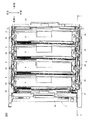
図2に示されるように、ドロワユニット3のドロワフレーム5は、平面視で四角枠状をなしている。具体的には、ドロワフレーム5は、左右方向に間隔を開けて対向する1対の側板21,22と、1対の側板21,22の各前端部間に架設されるフロントビーム23と、1対の側板の各後端部間に架設されるリヤビーム24とを備えている。
A fixing
2. Drawer Unit (1) Drawer Frame As shown in FIG. 2, the
図3に示されるように、4つの感光ドラム6は、1対の側板21,22の下端部間に架設されている。また、4つの帯電器7は、それぞれ感光ドラム6の後上方において、1対の側板21,22間に架設されている。
As shown in FIG. 3, the four
1対の側板21,22間において、各感光ドラム6の前上方かつ各帯電器7の前方には、現像カートリッジ8を装着するためのスペースが空けられている。現像カートリッジ8は、そのスペースに上方から装着される。
(2)カートリッジ案内部
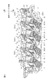
各側板21,22の内面には、4つの現像カートリッジ8が装着される各スペースと対向する位置に、現像カートリッジ8の着脱を案内するためのカートリッジ案内部25が形成されている。具体的には、各側板21,22の内面には、ドロワフレーム5の内側に突出する突条(リブ状の壁)26が形成されている。突条26は、現像カートリッジ8が装着される各スペースと対向する位置において、上方に開放される略U字状をなしている。そして、その突条26の略U字状の部分の内側がカートリッジ案内部25とされている。
Between the pair of
(2) Cartridge guide part A
突条26は、略U字状をなす各部分の下端部で途切れている。この途切れた部分の幅は、後述の軸カバー45の外径とほぼ同じであり、その途切れた部分において、突条26は、現像カートリッジ8がドロワフレーム5に装着された状態における感光ドラム6の回転中心と現像ローラ10の回転中心とを結ぶ直線と平行に延びている。
(3)押圧部材
各側板21,22には、4つの現像カートリッジ8が装着される各スペースに対応して、現像カートリッジ8を押圧するための4つの押圧部材31が設けられている。押圧部材31は、側面視で中心角約60°の扇形から周面の一部を切り欠いた略扇形状の板状をなしている。
The
(3) Pressing member Each
各側板21,22には、4つの揺動軸32が回転不能に保持されている。揺動軸32は、各押圧部材31の略扇形状の中心をなす部分と左右方向に対向する位置において、左右方向に延びている。
Four
そして、押圧部材31の略扇形状の中心をなす部分に揺動軸32の先端部が相対回転可能に挿通されることにより、押圧部材31は、揺動軸32により、揺動軸32を支点として揺動(回動)可能に支持されている。また、揺動軸32には、線ばね33が巻回されており、押圧部材31は、線ばね33により、左側から見て反時計回りに付勢されている。
(4)離間部材
また、図4に示されるように、各側板21,22には、各押圧部材31に対して左右方向の外側に、現像ローラ10を感光ドラム6から離間させるための離間部材34が設けられている。離間部材34は、前上端部が直角に屈曲する角部となる側面視略直角三角形状の板状をなし、線ばね(図示せず)により、左側から見て時計回りに付勢されている。
Then, the distal end portion of the
(4) Separating Member As shown in FIG. 4, each
また、離間部材34は、図3に示されるように、押圧部材31に対して後下方から対向する位置に、左右方向の内側に突出する作用部35を備えている。
3.現像カートリッジ
(1)筐体
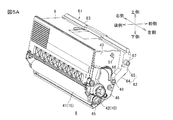
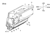
図5A,5B,5C,5D,6A,6B,6C,6Dに示されるように、現像カートリッジ8の筐体9は、側面視で下端部が狭まった略三角形状をなしている。
Further, as shown in FIG. 3, the
3. Developing Cartridge (1) Housing As shown in FIGS. 5A, 5B, 5C, 5D, 6A, 6B, 6C, and 6D, the
筐体9の下端部において、現像ローラ10が回転可能に保持されている。現像ローラ10は、図5A,5C,6A,6Cに示されるように、左右方向に延びる軸線を中心とする円柱状のローラ本体41と、ローラ本体41にその中心軸線に沿って挿通される現像ローラ軸42とを有している。現像ローラ軸42の両端部は、それぞれローラ本体41の左右両端面から突出し、筐体9の左側壁43および右側壁44を貫通して、左側壁43および右側壁44に回転可能に保持されている。現像ローラ軸42における左側壁43および右側壁44から突出する両端部には、軸カバー45が外嵌されている。
The developing
左側壁43の下端部には、図5A,5B,6A,6Bに示されるように、軸カバー45の上方の位置に、ギヤカバー46が取り付けられている。ギヤカバー46の内側には、現像ローラ10などに駆動力を伝達するためのギヤが収容されている。一方、右側壁44の下端部には、図5C,5D,6C,6Dに示されるように、電極カバー47が取り付けられている。
A
また、左側壁43には、図5A,5B,6A,6Bに示されるように、ギヤカバー46の上方であって、前端部の上下方向の中央部には、左右方向に延びる円柱状の支持軸48が突出して設けられている。一方、右側壁44には、図5C,5D,6C,6Dに示されるように、支持軸49が支持軸48と中心軸線が共通となる位置に突出して設けられている。支持軸48,49の左右方向の外側の端面は、後述の被押圧部67の左右方向の外側の端面より内側に位置している。
As shown in FIGS. 5A, 5B, 6A, and 6B, the
また、左側壁43および右側壁44には、図5A〜6Dに示されるように、支持軸48,49に対して前上方に離間した位置に、ストッパ50が突出して形成されている。また、左側壁43および右側壁44には、その上端部の左右方向の中央部に、ストッパ51が突出して形成されている。
(2)揺動部材
そして、現像カートリッジ8には、支持軸48,49に揺動可能に支持される揺動部材61が備えられている。揺動部材61は、1対のアーム部62と、1対のアーム部62を連結する連結部63とを有している。
Further, as shown in FIGS. 5A to 6D, the
(2) Oscillating Member
左右のアーム部62は、筐体9の外側に設けられ、2つのストッパ50,51の間で、それぞれ左側壁43および右側壁44に沿って延びている。具体的には、左右のアーム部62は、それぞれ支持軸48,49から前上方に延びる第1部分64と、第1部分64の上端部から後側に屈曲して、筐体9の上面を越える位置まで延びる第2部分65とを一体的に有している。
The left and
第1部分64の下端部には、貫通孔66が左右方向に貫通して形成されている。そして、貫通孔66に支持軸48,49が遊びを有して挿通(遊嵌)されることにより、左右のアーム部62がそれぞれ支持軸48,49に揺動可能に支持されている。
A through
第2部分65の長手方向の中央部には、円柱状の被押圧部67が左右方向の外側に突出して設けられている。被押圧部67は、第2部分65と一体に形成されている。
A columnar pressed
連結部63は、筐体9の上方において、左右のアーム部62の第2部分65の先端部間に架設されている。連結部63は、アーム部62と一体に形成されている。
4.現像ローラの押圧/離間
現像カートリッジ8がドロワフレーム5に装着された状態では、図3に示されるように、軸カバー45がカートリッジ案内部25の下端部(突条26の途切れた部分)に位置している。また、揺動部材61の第1部分64がストッパ50に当接して、揺動部材61が第1姿勢をなし、揺動部材61の被押圧部67が押圧部材31と離間部材34の作用部35との間に挟持されている。これにより、被押圧部67が押圧部材31から後下方に向かう押圧力を受け、この押圧力が揺動部材61を介して支持軸48,49に伝達されて、支持軸48,49が後下方に押圧され、現像ローラ10のローラ本体41が感光ドラム6に押圧される。
The connecting
4). Pressing / separation of the developing roller When the developing
カラープリンタ1は、動作モードとして、用紙Pにカラー画像を形成するカラーモードと、用紙Pにモノクロ画像を形成するモノクロモードとを有している。カラーモードでは、すべての感光ドラム6に対して現像ローラ10が圧接される。モノクロモードでは、ブラック用の感光ドラム6に対してのみ現像ローラ10が圧接され、イエロー、マゼンタおよびシアン用の感光ドラム6から現像ローラ10が離間される。
The
感光ドラム6から現像ローラ10が離間されるときには、本体ケーシング2内に設けられている直動カム(図示せず)が前後方向に移動されて、直動カムにより離間部材34の後端部が押し下げられる。これにより、離間部材34が左側から見て反時計回りに回動して、離間部材34の作用部35が被押圧部67を前上方に押し上げ、現像カートリッジ8が上方に移動する。その結果、現像ローラ10が感光ドラム6から離間する。
5.現像カートリッジの着脱
ドロワフレーム5に対する現像カートリッジ8の着脱は、ドロワフレーム5(ドロワユニット3)が本体ケーシング2外の引出位置に引き出された状態で行われる。
When the developing
5. Attaching / detaching the developing cartridge The attaching / detaching of the developing
ドロワフレーム5から現像カートリッジ8が離脱されるときには、揺動部材61の連結部63が把持されて、揺動部材61が後方に引き起こされる。これにより、図7Aに示されるように、揺動部材61が左側から見て反時計回りに回動し、被押圧部67が押圧部材31と離間部材34の作用部35との間から抜け出す。そして、アーム部62の第2部分65がストッパ51に当接すると、それ以上の揺動部材61の回動が阻止され、揺動部材61が第2姿勢をなす。
When the developing
その後、図7Bに示されるように、揺動部材61の連結部63が引き上げられる。すると、軸カバー45がカートリッジ案内部25に案内されつつ、具体的には、軸カバー45が突条26におけるカートリッジ案内部25の前側に形成されている部分に沿って移動しつつ、現像カートリッジ8が上方に移動する。
Thereafter, as shown in FIG. 7B, the connecting
そして、現像カートリッジ8の上方への移動が進み、図7Cに示されるように、軸カバー45が突条26から離れると、現像カートリッジ8がドロワフレーム5から離脱した状態となる。現像カートリッジ8がドロワフレーム5から離脱された状態では、揺動部材61の連結部63が把持されて、現像カートリッジ8が持ち運ばれる。このとき、連結部63は、現像カートリッジ8のハンドリングのための把手として機能する。
When the developing
ドロワフレーム5に現像カートリッジ8が装着されるときには、ドロワフレーム5の上方に現像カートリッジ8が配置され、現像ローラ10を下方に向けた姿勢で、現像カートリッジ8が感光ドラム6に向けて移動される。この移動の途中で、軸カバー45がカートリッジ案内部25に上方から差し入れられる。その後、現像カートリッジ8の移動に伴って、軸カバー45がカートリッジ案内部25に案内され、現像ローラ10が感光ドラム6に近づく方向に移動する。そして、軸カバー45がカートリッジ案内部25の下端部に達すると、現像ローラ10のローラ本体41が感光ドラム6に接触する。
When the developing
その後、揺動部材61の連結部63が把持されて、揺動部材61が前方に押し倒される。これにより、揺動部材61が左側から見て時計回りに回動し、被押圧部67が押圧部材31を持ち上げつつ、被押圧部67が押圧部材31と離間部材34の作用部35との間に入り込む。そして、アーム部62の第1部分64がストッパ50に当接すると、それ以上の揺動部材61の回動が阻止され、揺動部材61が第1姿勢をなす。以上により、ドロワフレーム5に対する現像カートリッジ8の装着が完了する。
6.揺動部材の第2姿勢から第1姿勢への強制変位
揺動部材61が第2姿勢から第1姿勢に変位されず、ドロワフレーム5に対する現像カートリッジ8の装着が未完了のまま、ドロワフレーム5が引出位置から本体ケーシング2内の収容位置に戻されるおそれがある。
Thereafter, the connecting
6). Forced displacement of the swinging member from the second posture to the first posture The swinging
そのため、図8Aに示されるように、本体ケーシング2内には、フロントカバー4の近傍に、当接部71が設けられている。当接部71は、たとえば、露光器11を支持する支持板72の下面に固定されている。当接部71は、第1姿勢をなす揺動部材61の連結部63と前後方向(水平方向)にオーバラップし、第2姿勢をなす揺動部材61の連結部63と前後方向にオーバラップしない。
Therefore, as shown in FIG. 8A, a
図8Bに示されるように、揺動部材61が第2姿勢から第1姿勢に変位されずに、ドロワフレーム5が引出位置から収容位置に向けて移動されると、その移動の途中で、第2姿勢をなす揺動部材61の連結部63が当接部71に当接する。その後、ドロワフレーム5がさらに移動されると、当接部71により連結部63が前方に押される。これにより、揺動部材61は、第1姿勢から第2姿勢に変位される。
As shown in FIG. 8B, when the
よって、図8Cに示されるように、ドロワフレーム5が収容位置に配置された状態では、すべての現像カートリッジ8の揺動部材61が第1姿勢をなす。
7.作用効果
(1)作用効果1
以上のように、現像カートリッジ8は、感光ドラム6および押圧部材31を備えるドロワユニット3(ドロワフレーム5)に対して着脱可能である。現像カートリッジ8の筐体9には、現像ローラ10が回転可能に支持されている。筐体9は、現像ローラ10の軸線方向である左右方向に対向する1対の左側壁43および右側壁44を備えている。
Therefore, as shown in FIG. 8C, in a state where the
7). Function and Effect (1) Function and
As described above, the developing
筐体9の外側には、揺動部材61が設けられている。揺動部材61は、左側壁43および右側壁44に沿って延びる1対のアーム部62と、各アーム部62から左右方向の外側に延びる被押圧部67とを有している。そして、揺動部材61は、左右方向に延びる軸線を中心として、第1姿勢と第2姿勢とに揺動可能に設けられている。揺動部材61が第1姿勢をなす状態で、被押圧部67が押圧部材31により押圧される。揺動部材61が第1姿勢から第2姿勢に変位されると、押圧部材31による被押圧部67の押圧が解除される。
A
被押圧部67が筐体9とは別部材である揺動部材61に設けられているので、被押圧部67の位置は、筐体9の左側壁43および右側壁44に配置される他部材の配置による制約を受けない。よって、被押圧部67の位置の自由度を増すことができる。
Since the pressed
また、押圧部材31による被押圧部67の押圧が繰り返されて、たとえ被押圧部67が破損しても、揺動部材61を新品と交換すれば、現像カートリッジ8を使用し続けることができる。よって、現像カートリッジ8を長期間にわたって使用することができる。
(2)作用効果2
1対のアーム部62は、連結部63により連結されている。そのため、1対のアーム部62を同時に揺動させることができる。
(3)作用効果3
連結部63は、把手を兼ねている。そのため、部品点数を増加させることなく、現像カートリッジ8を持ち運ぶときの操作性を向上させることができる。
(4)作用効果4
連結部63は、アーム部62と一体に形成されている。そのため、現像カートリッジ8の製造の際に、アーム部62と連結部63とを接続する必要がない。よって、現像カートリッジ8の製造に要する手間を軽減することができる。
(5)作用効果5
左側壁43および右側壁44とそれらに沿って延びるアーム部62との間には、それぞれ左右方向に延びる支持軸48,49が設けられている。支持軸48,49を支点として、揺動部材61を第1姿勢と第2姿勢とに揺動させることができる。
(6)作用効果6
支持軸48,49の一端部は、筐体9の左側壁43および右側壁44に固定されている。一方、支持軸48,49の他端部は、アーム部62に形成された貫通孔66に遊嵌されている。そのため、支持軸48,49を貫通孔66から抜くことにより、揺動部材61を筐体9から容易に取り外すことができる。また、貫通孔66に支持軸48,49を挿通させることにより、揺動部材61を筐体9に容易に取り付けることができる。よって、被押圧部67が破損したときなどに、揺動部材61を新品と簡単に交換することができる。
(7)作用効果7
支持軸48,49における左右方向の外側の端面は、被押圧部67における左右方向の外側の端面よりも左右方向の内側に配置されている。これにより、ドロワユニット3に対する現像カートリッジ8の着脱の際に、支持軸48,49が邪魔になることを防止できる。
(8)作用効果8
被押圧部67は、アーム部62と一体に形成されている。そのため、現像カートリッジ8の製造の際に、アーム部62に被押圧部67を取り付ける必要がない。よって、現像カートリッジ8の製造に要する手間を軽減することができる。
(9)作用効果9
アーム部62は、現像ローラ10の径方向に延び、その一端部が左側壁43および右側壁44に揺動可能に連結された第1部分64と、第1部分64の他端部から、第1部分64に沿った延長線に対して第1姿勢から第2姿勢に向かう方向の下流側である後側に延びる第2部分65とを有している。そして、揺動部材61が第1姿勢および第2姿勢のいずれの姿勢をなすときでも、連結部63が筐体9の上方に配置される。そのため、連結部63を容易に把持することができるので、連結部63を把持して、揺動部材61を第1姿勢と第2姿勢とに容易に揺動させることができる。
8.変形例
(1)第1変形例
揺動部材61は、図9に示されるように、連結部63を有していなくてもよい。この構成の場合、揺動部材61を第1姿勢と第2姿勢とに変位させるために、互いに分離された2つのアーム部62の両方を揺動させる必要がある。
(2)第2変形例
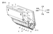
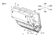
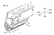
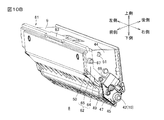
図5A〜6Dに示される構成では、支持軸48,49がそれぞれ左側壁43および右側壁44に突出して設けられている。しかしながら、支持軸48,49が形成される部分(位置)は、左側壁43および右側壁44に限らない。たとえば、図10A,10Bに示されるように、支持軸48,49は、それぞれギヤカバー46および電極カバー47に突出して形成されていてもよい。
(3)第3変形例
また、図11A,11B,12A,12Bに示される構成が採用されてもよい。図11A〜12Bの各図において、図5A〜6Dに示される各部に相当する部分には、それらの各部と同一の参照符号が付されている。
Further, even if the pressed
(2)
The pair of
(3)
The connecting
(4) Action effect 4
The connecting
(5)
(6)
One end portions of the
(7)
The outer end surfaces in the left-right direction of the
(8)
The pressed
(9)
The
8). Modified Example (1) First Modified Example As shown in FIG. 9, the oscillating
(2) Second Modification In the configuration shown in FIGS. 5A to 6D,
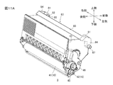
(3) Third Modification The configuration shown in FIGS. 11A, 11B, 12A, and 12B may be employed. 11A to 12B, parts corresponding to the parts shown in FIGS. 5A to 6D are denoted by the same reference numerals as those parts.
この構成では、現像カートリッジ8の筐体9の上面の左前端部および右前端部に、それぞれ軸受部81が設けられている。軸受部81には、軸受孔82が左右方向に貫通して形成されている。
In this configuration, bearing
現像カートリッジ8は、揺動部材83を備えている。揺動部材83は、1対のアーム部84と、1対のアーム部84を連結する連結部85とを一体的に有している。
The developing
左右のアーム部84は、側面視V字状に形成されている。各アーム部84の屈曲部分には、左右方向の内側に延びる支持軸86が形成されている。
The left and
連結部85は、筐体9の上方において、各アーム部84の先端部間に架設されている。
The connecting
各アーム部84の支持軸86が軸受孔82に左右方向の外側から遊びを有して挿通されることにより、揺動部材83(アーム部84)は、支持軸86を支点に第1姿勢と第2姿勢とに揺動可能に設けられている。揺動部材83が第1姿勢をなす状態では、図11A,11Bに示されるように、各アーム部84の下端部が筐体9の左側壁43および右側壁44の前端部に配置される。また、揺動部材83が第2姿勢をなす状態では、図12A,12Bに示されるように、各アーム部84の下端部は、揺動部材83が第1姿勢をなす状態での下端部の位置に対して後上方に離間した位置に配置される。
When the
そして、各アーム部84の下端部には、円柱状の被押圧部87が左右方向の外側に突出して設けられている。
A columnar pressed
この構成によっても、図5A〜6Dに示される構成の場合と同様な作用効果を奏することができる。
(4)その他の変形例
図5A〜6Dに示される構成において、アーム部62における貫通孔66が形成されている位置に、貫通孔66に代えて、支持軸48,49が左右方向の内側に突出して形成され、それらの支持軸48,49の先端部がそれぞれ左側壁43および右側壁44に回動可能に支持されてもよい。
Also with this configuration, the same operational effects as in the configuration shown in FIGS. 5A to 6D can be obtained.
(4) Other Modifications In the configuration shown in FIGS. 5A to 6D, the
また、図10A,10Bに示される構成において、アーム部62における貫通孔66が形成されている位置に、貫通孔66に代えて、支持軸48,49が左右方向の内側に突出して形成され、それらの支持軸48,49の先端部がそれぞれギヤカバー46および電極カバー47に回動可能に支持されてもよい。
10A and 10B, instead of the through
また、図11A〜12Bに示される構成において、各軸受部81における軸受孔82が形成されている位置に、軸受孔82に代えて、支持軸86が左右方向の外側に突出して形成され、それらの支持軸86の先端部がそれぞれアーム部84の屈曲部分に回動可能に支持されてもよい。
In addition, in the configuration shown in FIGS. 11A to 12B, instead of the bearing holes 82,
その他、前述の構成には、特許請求の範囲に記載された事項の範囲で種々の設計変更を施すことが可能である。 In addition, various design changes can be made to the above-described configuration within the scope of the matters described in the claims.
3 ドロワユニット
6 感光ドラム
8 現像カートリッジ
9 筐体
10 現像ローラ
31 押圧部材
43 左側壁
44 右側壁
48 支持軸
49 支持軸
61 揺動部材
62 アーム部
63 連結部
64 第1部分
65 第2部分
66 貫通孔
67 被押圧部
83 揺動部材
84 アーム部
85 連結部
86 支持軸
87 被押圧部
3
Claims (10)
前記感光体に現像剤を供給する現像ローラと、
前記現像ローラの軸線方向に対向する1対の側壁を有し、前記現像ローラを回転可能に支持する筐体と、
前記筐体の外側で各前記側壁に沿って延びる1対のアーム部および各前記アーム部から前記軸線方向の外側に延びる被押圧部を有し、前記被押圧部が前記押圧部材により押圧される第1姿勢と、前記押圧部材による前記被押圧部の押圧が解除される第2姿勢とに、前記軸線方向に延びる軸線を中心として揺動可能に設けられた揺動部材とを備える、現像カートリッジ。 A developing cartridge that is attachable to and detachable from a photoreceptor unit including a photoreceptor and a pressing member,
A developing roller for supplying a developer to the photoreceptor;
A housing having a pair of side walls facing in the axial direction of the developing roller and rotatably supporting the developing roller;
A pair of arm portions extending along the side walls on the outside of the casing and a pressed portion extending outward in the axial direction from the arm portions, and the pressed portion is pressed by the pressing member. A developing cartridge comprising a first posture and a swinging member provided so as to be swingable about an axis extending in the axial direction in a second posture in which the pressing of the pressed portion by the pressing member is released. .
前記揺動部材は、前記支持軸を支点として揺動可能に設けられている、請求項1〜4のいずれか一項に記載の現像カートリッジ。 Provided between each of the side walls and each of the arm portions, each including two support shafts extending in the axial direction;
The developing cartridge according to claim 1, wherein the swing member is swingably provided with the support shaft as a fulcrum.
前記被押圧部は、前記第2部分から前記軸線方向の外側に延びている、請求項1〜8のいずれか一項に記載の現像カートリッジ。 The arm portion extends in the radial direction of the developing roller, and one end portion of the arm portion is swingably connected to the side wall, and the other end portion of the first portion extends along the first portion. A second portion extending downstream in the direction from the first posture to the second posture with respect to the extension line,
The developing cartridge according to claim 1, wherein the pressed portion extends outward in the axial direction from the second portion.
前記所定方向に互いに間隔を空けて並列に配置される複数の感光体および各前記感光体に対応して設けられた複数の押圧部材を有する感光体ユニットと、
各前記感光体に対応して設けられた、請求項1〜9のいずれか一項に記載の複数の現像カートリッジとを備える、プロセスユニット。 A process unit movable in a predetermined direction with respect to the apparatus main body of the image forming apparatus,
A plurality of photoconductors arranged in parallel at intervals in the predetermined direction and a photoconductor unit having a plurality of pressing members provided corresponding to the photoconductors;
A process unit comprising a plurality of developing cartridges according to any one of claims 1 to 9, provided corresponding to each of the photoconductors.
Priority Applications (3)
| Application Number | Priority Date | Filing Date | Title |
|---|---|---|---|
| JP2010254088A JP5707883B2 (en) | 2010-11-12 | 2010-11-12 | Process unit |
| CN201110357886.1A CN102467030B (en) | 2010-11-12 | 2011-11-11 | Developing cartridge and process unit |
| US13/294,208 US8897670B2 (en) | 2010-11-12 | 2011-11-11 | Developing cartridge and process unit |
Applications Claiming Priority (1)
| Application Number | Priority Date | Filing Date | Title |
|---|---|---|---|
| JP2010254088A JP5707883B2 (en) | 2010-11-12 | 2010-11-12 | Process unit |
Publications (2)
| Publication Number | Publication Date |
|---|---|
| JP2012103620A true JP2012103620A (en) | 2012-05-31 |
| JP5707883B2 JP5707883B2 (en) | 2015-04-30 |
Family
ID=46047860
Family Applications (1)
| Application Number | Title | Priority Date | Filing Date |
|---|---|---|---|
| JP2010254088A Active JP5707883B2 (en) | 2010-11-12 | 2010-11-12 | Process unit |
Country Status (3)
| Country | Link |
|---|---|
| US (1) | US8897670B2 (en) |
| JP (1) | JP5707883B2 (en) |
| CN (1) | CN102467030B (en) |
Cited By (1)
| Publication number | Priority date | Publication date | Assignee | Title |
|---|---|---|---|---|
| JP2018169521A (en) * | 2017-03-30 | 2018-11-01 | ブラザー工業株式会社 | Developing cartridge |
Families Citing this family (3)
| Publication number | Priority date | Publication date | Assignee | Title |
|---|---|---|---|---|
| JP7047541B2 (en) * | 2018-03-30 | 2022-04-05 | ブラザー工業株式会社 | Develop cartridge |
| JP1647818S (en) * | 2019-06-14 | 2019-12-16 | Printer paper feeder | |
| USD952030S1 (en) * | 2019-10-23 | 2022-05-17 | Lexmark International, Inc. | Toner cartridge |
Citations (8)
| Publication number | Priority date | Publication date | Assignee | Title |
|---|---|---|---|---|
| JPS60102663A (en) * | 1983-11-09 | 1985-06-06 | Canon Inc | Developing device |
| JPS61230159A (en) * | 1985-04-04 | 1986-10-14 | Minolta Camera Co Ltd | Image forming device |
| JPS6299764A (en) * | 1985-10-26 | 1987-05-09 | Canon Inc | Developing member shutter opening and closing mechanism for developing device |
| JPH05341635A (en) * | 1992-06-09 | 1993-12-24 | Nagano Japan Radio Co | Developing device for printer |
| JP2003084647A (en) * | 2001-09-13 | 2003-03-19 | Brother Ind Ltd | Image forming apparatus and development unit |
| JP2007178654A (en) * | 2005-12-27 | 2007-07-12 | Brother Ind Ltd | Image forming apparatus |
| US20070280733A1 (en) * | 2006-05-30 | 2007-12-06 | Brother Kogyo Kabushiki Kaisha | Photosensitive unit and developer cartridge |
| US20100166453A1 (en) * | 2008-12-26 | 2010-07-01 | Brother Kogyo Kabushiki Kaisha | Image Forming Apparatus and Developing Cartridge |
Family Cites Families (10)
| Publication number | Priority date | Publication date | Assignee | Title |
|---|---|---|---|---|
| JP4737349B2 (en) | 1999-02-26 | 2011-07-27 | ブラザー工業株式会社 | Image forming apparatus |
| US6330410B1 (en) | 1999-02-26 | 2001-12-11 | Brother Kogyo Kabushiki Kaisha | Photosensitive member cartridge |
| CN2627544Y (en) | 2001-09-13 | 2004-07-21 | 兄弟工业株式会社 | Imaging device and processing unit used thereof |
| US6751428B2 (en) | 2001-09-13 | 2004-06-15 | Brother Kogyo Kabushiki Kaisha | Image forming device and detachably loaded process unit |
| AU153015S (en) | 2002-03-25 | 2003-09-03 | Brother Ind Ltd | Toner cartridge |
| AU153016S (en) | 2002-03-25 | 2003-09-03 | Brother Ind Ltd | Photosensitive drum unit |
| JP4089639B2 (en) * | 2004-02-27 | 2008-05-28 | ブラザー工業株式会社 | Process cartridge and image forming apparatus |
| JP4701830B2 (en) | 2005-05-11 | 2011-06-15 | ブラザー工業株式会社 | Process cartridge and image forming apparatus |
| JP4280770B2 (en) * | 2006-01-11 | 2009-06-17 | キヤノン株式会社 | Process cartridge and electrophotographic image forming apparatus |
| JP2010072307A (en) * | 2008-09-18 | 2010-04-02 | Canon Inc | Developing cartridge and image forming apparatus |
-
2010
- 2010-11-12 JP JP2010254088A patent/JP5707883B2/en active Active
-
2011
- 2011-11-11 CN CN201110357886.1A patent/CN102467030B/en active Active
- 2011-11-11 US US13/294,208 patent/US8897670B2/en active Active
Patent Citations (11)
| Publication number | Priority date | Publication date | Assignee | Title |
|---|---|---|---|---|
| JPS60102663A (en) * | 1983-11-09 | 1985-06-06 | Canon Inc | Developing device |
| JPS61230159A (en) * | 1985-04-04 | 1986-10-14 | Minolta Camera Co Ltd | Image forming device |
| JPS6299764A (en) * | 1985-10-26 | 1987-05-09 | Canon Inc | Developing member shutter opening and closing mechanism for developing device |
| JPH05341635A (en) * | 1992-06-09 | 1993-12-24 | Nagano Japan Radio Co | Developing device for printer |
| JP2003084647A (en) * | 2001-09-13 | 2003-03-19 | Brother Ind Ltd | Image forming apparatus and development unit |
| JP2007178654A (en) * | 2005-12-27 | 2007-07-12 | Brother Ind Ltd | Image forming apparatus |
| US20070183814A1 (en) * | 2005-12-27 | 2007-08-09 | Brother Kogyo Kabushiki Kaisha | Image Foming Device |
| US20070280733A1 (en) * | 2006-05-30 | 2007-12-06 | Brother Kogyo Kabushiki Kaisha | Photosensitive unit and developer cartridge |
| JP2007322553A (en) * | 2006-05-30 | 2007-12-13 | Brother Ind Ltd | Photoreceptor unit and development cartridge |
| US20100166453A1 (en) * | 2008-12-26 | 2010-07-01 | Brother Kogyo Kabushiki Kaisha | Image Forming Apparatus and Developing Cartridge |
| JP2010156790A (en) * | 2008-12-26 | 2010-07-15 | Brother Ind Ltd | Image forming apparatus and developing cartridge |
Cited By (1)
| Publication number | Priority date | Publication date | Assignee | Title |
|---|---|---|---|---|
| JP2018169521A (en) * | 2017-03-30 | 2018-11-01 | ブラザー工業株式会社 | Developing cartridge |
Also Published As
| Publication number | Publication date |
|---|---|
| CN102467030A (en) | 2012-05-23 |
| CN102467030B (en) | 2014-10-08 |
| US8897670B2 (en) | 2014-11-25 |
| JP5707883B2 (en) | 2015-04-30 |
| US20120121292A1 (en) | 2012-05-17 |
Similar Documents
| Publication | Publication Date | Title |
|---|---|---|
| US9335655B2 (en) | Developing cartridge | |
| JP5838611B2 (en) | Image forming apparatus | |
| JP4600535B2 (en) | Image forming apparatus | |
| JP5861581B2 (en) | Process cartridge and image forming apparatus | |
| JP5929174B2 (en) | Image forming apparatus | |
| JP2013182036A (en) | Image forming apparatus | |
| JP5991163B2 (en) | Cartridge and image forming apparatus | |
| JP5707883B2 (en) | Process unit | |
| JP2011248295A (en) | Process unit | |
| JP5857541B2 (en) | Process cartridge | |
| WO2014010127A1 (en) | Process cartridge and image forming device | |
| JP5136601B2 (en) | Tandem drum unit | |
| JP6056420B2 (en) | Photoconductor cartridge | |
| JP5994443B2 (en) | Process cartridge | |
| JP4569644B2 (en) | Image forming apparatus | |
| JP6164351B2 (en) | Cartridge and image forming apparatus | |
| JP6011085B2 (en) | cartridge | |
| WO2014010125A1 (en) | Cartridge | |
| JP2015099222A (en) | Photoreceptor cartridge | |
| WO2014010119A1 (en) | Cartridge | |
| JP2014066843A (en) | Process cartridge, developing cartridge, and image forming apparatus |
Legal Events
| Date | Code | Title | Description |
|---|---|---|---|
| A621 | Written request for application examination |
Free format text: JAPANESE INTERMEDIATE CODE: A621 Effective date: 20131108 |
|
| A977 | Report on retrieval |
Free format text: JAPANESE INTERMEDIATE CODE: A971007 Effective date: 20140820 |
|
| A131 | Notification of reasons for refusal |
Free format text: JAPANESE INTERMEDIATE CODE: A131 Effective date: 20140902 |
|
| A521 | Request for written amendment filed |
Free format text: JAPANESE INTERMEDIATE CODE: A523 Effective date: 20141104 |
|
| TRDD | Decision of grant or rejection written | ||
| A01 | Written decision to grant a patent or to grant a registration (utility model) |
Free format text: JAPANESE INTERMEDIATE CODE: A01 Effective date: 20150203 |
|
| A61 | First payment of annual fees (during grant procedure) |
Free format text: JAPANESE INTERMEDIATE CODE: A61 Effective date: 20150216 |
|
| R150 | Certificate of patent or registration of utility model |
Ref document number: 5707883 Country of ref document: JP Free format text: JAPANESE INTERMEDIATE CODE: R150 |