JP2012102877A - Gearing profile with constant torque - Google Patents
Gearing profile with constant torque Download PDFInfo
- Publication number
- JP2012102877A JP2012102877A JP2011247198A JP2011247198A JP2012102877A JP 2012102877 A JP2012102877 A JP 2012102877A JP 2011247198 A JP2011247198 A JP 2011247198A JP 2011247198 A JP2011247198 A JP 2011247198A JP 2012102877 A JP2012102877 A JP 2012102877A
- Authority
- JP
- Japan
- Prior art keywords
- tooth
- wheel
- profile
- edge
- transmission
- Prior art date
- Legal status (The legal status is an assumption and is not a legal conclusion. Google has not performed a legal analysis and makes no representation as to the accuracy of the status listed.)
- Granted
Links
Images


Classifications
-
- G—PHYSICS
- G04—HOROLOGY
- G04B—MECHANICALLY-DRIVEN CLOCKS OR WATCHES; MECHANICAL PARTS OF CLOCKS OR WATCHES IN GENERAL; TIME PIECES USING THE POSITION OF THE SUN, MOON OR STARS
- G04B13/00—Gearwork
- G04B13/02—Wheels; Pinions; Spindles; Pivots
- G04B13/027—Wheels; Pinions; Spindles; Pivots planar toothing: shape and design
-
- F—MECHANICAL ENGINEERING; LIGHTING; HEATING; WEAPONS; BLASTING
- F16—ENGINEERING ELEMENTS AND UNITS; GENERAL MEASURES FOR PRODUCING AND MAINTAINING EFFECTIVE FUNCTIONING OF MACHINES OR INSTALLATIONS; THERMAL INSULATION IN GENERAL
- F16H—GEARING
- F16H55/00—Elements with teeth or friction surfaces for conveying motion; Worms, pulleys or sheaves for gearing mechanisms
- F16H55/02—Toothed members; Worms
- F16H55/08—Profiling
-
- Y—GENERAL TAGGING OF NEW TECHNOLOGICAL DEVELOPMENTS; GENERAL TAGGING OF CROSS-SECTIONAL TECHNOLOGIES SPANNING OVER SEVERAL SECTIONS OF THE IPC; TECHNICAL SUBJECTS COVERED BY FORMER USPC CROSS-REFERENCE ART COLLECTIONS [XRACs] AND DIGESTS
- Y10—TECHNICAL SUBJECTS COVERED BY FORMER USPC
- Y10T—TECHNICAL SUBJECTS COVERED BY FORMER US CLASSIFICATION
- Y10T74/00—Machine element or mechanism
- Y10T74/19—Gearing
- Y10T74/19949—Teeth
- Y10T74/19963—Spur
- Y10T74/19972—Spur form
Landscapes
- Engineering & Computer Science (AREA)
- General Engineering & Computer Science (AREA)
- Physics & Mathematics (AREA)
- General Physics & Mathematics (AREA)
- Mechanical Engineering (AREA)
- Gears, Cams (AREA)
Abstract
Description
本発明は、一般に、ウォッチのギヤ列を構成しているホイールとピニオンに関し、更に詳しくは、これらのホイールの歯のプロフィールとこれらのピニオンのプロフィール(以下、プロフィールを単に「輪郭」と呼ぶ。)に関する。本発明は、また本発明によるホイールやピニオンを含む時計以外に、ウォッチのムーブメントに関するものである。 The present invention relates generally to the wheels and pinions that make up the gear train of a watch, and more particularly to the tooth profiles of these wheels and the profiles of these pinions (hereinafter the profiles are simply referred to as “contours”). About. The present invention also relates to a watch movement in addition to a timepiece including a wheel and a pinion according to the present invention.
ウォッチにおいて、スプラングバランスの振動が完全に等時性を持たないことは、知られている。換言すれば、この振動の継続時間(周期)は、振動の振幅から完全に独立してはいない。また、テン輪(バランスホイール)の振動の総角度がリミット値を超える場合は、このテン輪ローラーのピンはフォークの外側に当接し、それによってウォッチのムーブメントにかなりの進みが生じることも知られている。従って、この後者については、ノックすると言われている。上述のことから、テン輪の振動の振幅を出来る限り等しくすることが望ましいということが分かる。 In watches, it is known that the vibration of the sprung balance is not completely isochronous. In other words, the duration (cycle) of this vibration is not completely independent of the amplitude of the vibration. It is also known that if the total angle of vibration of the ten wheel (balance wheel) exceeds the limit value, the pin of the ten wheel roller abuts the outside of the fork, which causes a significant advance in the watch movement. ing. Therefore, the latter is said to knock. From the above, it can be seen that it is desirable to make the vibration amplitude of the ten wheel as equal as possible.
螺旋のテン輪の振動の振幅の変動には、複数の原因がある。ウォッチが水平位置から垂直位置に向かって変位すると、このテン輪のピボットによって被る摩擦の強度が増加することは、当業者には周知である。他方、脱進機構によってテン輪に伝達される力の変動によって、このテン輪の振幅に同様に変動を引き起こすことがよく知られている。 There are a plurality of causes for fluctuations in the amplitude of vibration of the spiral ten wheel. It is well known to those skilled in the art that when the watch is displaced from a horizontal position toward a vertical position, the strength of the friction experienced by the pivot of the ten wheel increases. On the other hand, it is well known that the fluctuation of the force transmitted to the ten wheel by the escape mechanism causes a similar fluctuation in the amplitude of the ten wheel.
様々な要因が、脱進機構からテン輪に伝達される力の変動の根元にあると考えられる。第1に、バレル・スプリングの張力は、この後者の巻回の程度に依る。これは、通常、パワーリザーブの関数として、ギヤ列によって伝達される力の変動となる。他方、伝動装置(ギヤリング)において、嵌合する2つの歯のフランクの輪郭間の接触点は、歯の駆動中に、半径方向に移動し、駆動歯のヘッドの方へ移動する。この現象は添付図1に概略的に例示され、82個の歯とピッチ円半径R1を有する駆動輪10が、12個の歯とピッチ円半径R2を有する被駆動輪11と嵌合するのが示されている。矢印は、回転方向を示す。
この接触点の軌跡(嵌合線12と呼ばれる)は、ポイントAからポイントBまで延在し、2つのホイールの中心を結ぶ中心線13の近傍でホイールの2つのピッチ円を横切る。
公知の伝動装置においては、この駆動輪の被駆動輪との接触点がこの嵌合線に沿って進行する間、伝達されるトルクと受け取られるトルク間の比は一定ではない。
これに反して、ある歯の駆動中に、この比は、図1の垂直中心スケールの反対側で、例えば、曲線14が示すように、変動する。
Various factors are considered to be the basis of fluctuations in the force transmitted from the escapement mechanism to the ten wheel. First, the tension of the barrel spring depends on the degree of this latter winding. This is usually a variation in the force transmitted by the gear train as a function of power reserve. On the other hand, in the transmission (gearing), the point of contact between the contours of the two tooth flanks to be fitted moves in the radial direction and moves towards the head of the drive tooth during tooth drive. This phenomenon is schematically illustrated in the accompanying FIG. 1, where a
The trajectory of this contact point (referred to as the fitting line 12) extends from point A to point B and crosses the two pitch circles of the wheel in the vicinity of the
In known transmissions, the ratio between the transmitted torque and the received torque is not constant while the point of contact of this drive wheel with the driven wheel travels along this fitting line.
On the other hand, during the drive of a tooth, this ratio fluctuates on the opposite side of the vertical center scale of FIG. 1, for example, as
ウォッチのムーブメントにおいて、バレルから脱進機構へと力を伝達するのは、ギヤ列である。このギヤ列がマルチプライングギヤ列であることは知られている。従って、このギヤ列の下流側端部で、脱進機構ホイールが秒あたり数ステップだけ正常に進むならば、このギヤ列の上流の部分はこの同じ期間中殆ど移動しない。これらの状態においては、ギヤ列の上流の部分にある単一の歯の駆動は、テン輪のかなりの数の振動の間続くことができる。従って、伝達装置の上流側の1つの歯の駆動中に伝達されるトルクの変動は、一般的に、テン輪の振動の振幅に影響を及ぼすのに十分な時間の間続く。 In the watch movement, it is the gear train that transmits the force from the barrel to the escapement mechanism. It is known that this gear train is a multiplying gear train. Thus, at the downstream end of the gear train, if the escapement mechanism wheel normally proceeds a few steps per second, the upstream portion of the gear train will hardly move during the same period. In these conditions, the drive of a single tooth in the upstream part of the gear train can last for a significant number of vibrations of the ten wheel. Thus, the variation in torque transmitted during the drive of one tooth upstream of the transmission device generally lasts for a time sufficient to affect the amplitude of the vibration of the ten wheel.
最終的には、脱進機構からテン輪へと伝達される力は、1つのタイムピースから他のタイムピースに同様に変化することができ、これらのタイムピースが理論的に同一の場合であっても、そのようになる。事実、時計および時計の製造の特徴である小型化の高度さのため、複数のホイールとウォッチのピニオンの位置決めの製造許容度は、このウォッチのギヤ列によって伝達される力に大いに影響を及ぼすのに十分でありえる。その理由は、公知の伝動装置(ギヤ)の輪郭について、この2つの歯付きホイールの回転軸間の距離が理論値から外れるや否や伝動装置において伝達されるトルクが大いに変化するからである。
軸心の距離の変動に対するこの伝動装置の感度の主な不利点は、ノッキングのあらゆるリスクを無くすためにウォッチのムーブメントの各例のテン輪の振動の振幅を相当な時間に亘って計測する必要があることだ。
Eventually, the force transmitted from the escapement mechanism to the wheel can vary from one timepiece to another, as long as these timepieces are theoretically identical. Even so. In fact, due to the high degree of miniaturization that is characteristic of watches and watchmaking, the manufacturing tolerance of positioning of multiple wheels and watch pinions greatly affects the force transmitted by this watch gear train. Can be enough. The reason for this is that, for the contour of a known transmission device (gear), the torque transmitted in the transmission device changes greatly as soon as the distance between the rotational axes of the two toothed wheels deviates from the theoretical value.
The main disadvantage of this gearing's sensitivity to axial distance variations is the need to measure the vibration amplitude of the watch ring for each instance of the watch movement over a considerable amount of time to eliminate any risk of knocking. There is.
時計および時計の製造の分野において、例えば歯付きホイールの歯の輪郭とピニオンの刃の輪郭を、ある円に対するサイクロイド、エピサイクロイド、インボリュートなどの幾何学的な曲線に基づいて決定することは、知られている。このようにして得られたホイールとピニオンはある「比例した伝達」を与えることができる特徴、即ち、換言すれば、1つの歯の駆動中、一定のままである回転速度を伝達する特徴を有する。更に、歯を有し、その歯の輪郭が円に対するインボリュート(以下、円に対するインボリュートを、単に「インボリュート」と呼ぶ。)に基づいているホイールおよびピニオンは、この2つのホイールの軸間の距離がこの理論値から外れている場合でさえ、この同じ伝達比で、比例した伝達ができるという追加的な特徴を有する。 In the field of watches and watchmaking, for example, it is known to determine the tooth profile of a toothed wheel and the pinion blade profile based on geometric curves such as cycloid, epicycloid, involute etc. for a circle. It has been. The wheel and pinion obtained in this way have the characteristic of giving a certain "proportional transmission", i.e. the characteristic of transmitting a rotational speed that remains constant during the drive of one tooth. . Furthermore, wheels and pinions that have teeth and whose tooth profile is based on an involute with respect to a circle (hereinafter, the involute with respect to the circle is simply referred to as “involute”) have a distance between the axes of the two wheels. Even when deviating from this theoretical value, this same transmission ratio has the additional feature that proportional transmission is possible.
図2A(インボリュートを有する伝動装置を表す)は、24個の歯を有するホイール1と16個の歯を有するホイール2との嵌合を示す。図2Aは、更に、この2つのホイールの各々に重畳された2つの同心円を示す。これらの2つの円(それぞれの参照符号はB1、B2)のうち小さい方の円は、このインボリュートのベース円である。大きい方の円(それぞれの参照符号はP1、P2)は、ピッチ円である。このホイール1のピッチ円P1とホイール2のピッチ円P2は、定義上一点で接触する。更に、これらのピッチ円の半径d1とd2の比は、この伝動装置の伝達比に等しく選択される。ここで注目すべきことは、これらのピッチ円の半径d1とd2に反して、この2つのベース円B1とB2の半径R1とR2が、2つのホイールの中心間の距離に依存しないことである。しかしながら、定義上、それらは、d1およびd2と同じ比である。
FIG. 2A (representing a transmission with involute) shows the fitting of a
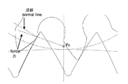
噛合線7を、再び、図2A、2Bに示す。この図示の例において、この嵌合線は2点AとBによって区切られた直線の線分の形状を有することが見て取れる。更に注目すべきことは、インボリュートを有する伝動装置の示差的特徴によれば、この嵌合線7にサブテンドする直線はこの2つのベース円B1とB2に対して正しく接線方向(タンジェンシャル)であることである。インボリュートを有する伝動装置の別の示差的特徴は、この接触点での2つの歯のエッジに共通な法線は、嵌合線の方向に、常に指向している(図2B)ことである。インボリュートを有する伝動装置の有利な特徴は、駆動輪と被駆動輪の角速度間の比が一定のままであって、かつ2つのホイール間の軸中心距離から独立していることである。換言すれば、すでに述べたように、インボリュートを有する伝動装置は、この2つのホイールの軸間の距離が公称値から外れているときでも、同じ伝達比で、比例した伝達を与えるという特徴を有することである。前述したことから、インボリュートを有する伝動装置によって伝達されるトルクは、2つのホイール間の軸中心距離がどうであろうと、歯の駆動中一定のままであるとの結論を出したくなるかもしれない。しかしながら、そのように考えるのは、この伝動装置がもはや平衡状態にないとなるや否や避けられない摩擦力を無視することとなる。事実、これらのホイールの回転には、相互に接触している面の滑りと、従ってまた接触しているこの2つの歯のフランクに接線方向(タンジェンシャル)である摩擦力とが常に付随する。これらの摩擦力は、この接触点でこの2つの歯のエッジに垂直な共通線に対して垂直であることが理解されよう。これらの摩擦力は、従って、伝達される力を嵌合線の方向から散開(ダイバージ)させる効果を有する。図2Bに類似の図3を参照すれば、力は互いに接触しているエッジによって及ぼされているのが知れる(これらの力は、2つの歯間の接触点に起源を持つ2本の対向する矢で示されている)。これらの力の方向は、嵌合線と共線的でないことが分かる。力と嵌合線間の散開(ダイバージェンス)により、伝達されるトルクが歯の駆動中一定でないということである。 The meshing line 7 is again shown in FIGS. 2A and 2B. In this illustrated example, it can be seen that the fitting line has a shape of a straight line segment separated by two points A and B. Further noteworthy is that according to the differential characteristics of the transmission with involute, the straight line subtending to this fitting line 7 is correctly tangential to the two base circles B1 and B2. That is. Another differential feature of the transmission with involute is that the normal common to the two tooth edges at this contact point is always oriented in the direction of the mating line (FIG. 2B). An advantageous feature of a transmission with an involute is that the ratio between the angular velocities of the driving and driven wheels remains constant and is independent of the axial center distance between the two wheels. In other words, as already mentioned, a transmission with an involute has the characteristic of providing a proportional transmission with the same transmission ratio even when the distance between the axes of the two wheels is outside the nominal value. That is. From the foregoing, it may be tempting to conclude that the torque transmitted by the transmission with involute remains constant during tooth drive, whatever the axial center distance between the two wheels. . However, to do so would neglect the inevitable frictional forces as soon as this transmission is no longer in equilibrium. In fact, the rotation of these wheels is always accompanied by slippage of the surfaces that are in contact with each other and, therefore, friction forces that are tangential to the flank of the two teeth that are also in contact. It will be appreciated that these frictional forces are perpendicular to a common line perpendicular to the edges of the two teeth at this point of contact. These frictional forces therefore have the effect of diverging the transmitted force from the direction of the mating line. Referring to FIG. 3, which is similar to FIG. 2B, it can be seen that the forces are exerted by edges that are in contact with each other (the two forces originate from the point of contact between the two teeth). Indicated by arrows). It can be seen that the direction of these forces is not collinear with the mating line. The transmitted torque is not constant during tooth drive due to the divergence between the force and the mating line.
事実、一定のトルクを伝達するために、歯の駆動の初めから終わりまで、2つの歯間の接触点での力は、この中心線の同一点(図8A、8Bおよび8Cにおける参照符号P0)に向かって、コンスタントに指向されていることが必要であるということが示される。従って、上述のことから、この接触している歯が摩擦なしで互いの上を滑ることができない限り、インボリュートを有する伝動装置は一定のトルクを伝達することができないということが理解されよう。 In fact, in order to transmit a constant torque, the force at the contact point between the two teeth from the beginning to the end of the tooth drive is the same point of this centerline (reference symbol P 0 in FIGS. 8A, 8B and 8C). ) Towards the need for constant orientation. Thus, it will be appreciated from the foregoing that transmissions with involute cannot transmit a constant torque unless the contacting teeth can slide on each other without friction.
本発明の目的は、従って、2つのホイールの軸間の距離が理論値から外れるときでも、歯の駆動中一定のトルクを伝達する特性を有する伝動装置の輪郭を提供することによって従来技術の不利な点を改善することである。本発明は、一方では、請求項1に従うホイールまたはピニオンを提供することによって、そして、他方では、本発明によるホイールまたはピニオンを含むウォッチのムーブメントや時計を提供することによって、この目的を達成する。
The object of the present invention is therefore to provide a transmission profile that has the property of transmitting a constant torque during tooth drive even when the distance between the axes of the two wheels deviates from the theoretical value. It is to improve this point. The invention achieves this object on the one hand by providing a wheel or pinion according to
本発明の他の特徴および効果は、添付図を参照して以下の説明から明らかとなる。なお、これらの図は単に例示的なものであり、発明を限定するものではない。 Other features and advantages of the present invention will become apparent from the following description with reference to the accompanying drawings. These figures are merely illustrative and do not limit the invention.
図4は、本発明による伝動装置の2つの歯17、18間の接触点(参照符号P0)がこの中心線上に位置する場合の部分的な模式図である。以下、図4の伝動装置を作り出すプロセスの簡単な説明を行う。
FIG. 4 is a partial schematic view when the contact point (reference symbol P 0 ) between the two
今説明しようとしているプロセスは、あるパラメータの値が既に公知(または選択済み)である瞬間から始まるものとする。
これらのパラメータは、以下の通り:
− 公称軸中心距離「d」;
− この軸中心距離の許容度、換言すると、間隔[dmin、dmax]で、この範囲内では歯の輪郭は一定のトルクを与えなければならない;
− 2つのホイールの歯の数「z1」と「z2」;
− 2つの歯間の接触点での摩擦係数「μ」。
The process that we are going to describe now starts at the moment when the value of a parameter is already known (or selected).
These parameters are as follows:
-Nominal axial center distance "d";
-Tolerance of this axial center distance, in other words, at intervals [dmin, dmax], within this range the tooth profile must give a constant torque;
The number of teeth on the two wheels “z 1 ” and “z 2 ”;
The coefficient of friction “μ” at the point of contact between the two teeth.
1.このプロセスのこの第1のステップは、伝動装置が持たねばならない効率「ε」を定めることである。 1. This first step in the process is to define the efficiency “ε” that the transmission must have.
ホイール1によってホイール2上に及ぼされるトルクをM1→2で示し、ホイール1上に及ぼされるホイール2の反応を、M2→1で示すと、歯の駆動中にホイール1によってホイール2に与えられる仕事(エネルギー)は2π/z2 M1→2に等しく、ホイール2に受け取られるこのエネルギーは2π/z2 M2→1に等しい。
これらの状態において、効率出力がεに等しいとすると、2π/z2 M2→1 =ε2π/z1 M1→2または等価的に
![]()
In these states, if the efficiency output is equal to ε, 2π / z 2 M 2 → 1 = ε2π / z 1 M 1 → 2 or equivalently
![]()
本発明によってこの輪郭を構成するためには、この平均効率「ε」を選択することが必要である。殆ど1に近いεの値、例えば間隔[0.9; 0.99]内の値が、好ましくは選択される。 In order to construct this contour according to the invention, it is necessary to select this average efficiency “ε”. A value of ε almost close to 1, for example a value in the interval [0.9; 0.99] is preferably selected.
d1をホイール1の中心とP0(即ち、中心線と嵌合線の交点)間の距離とし、d2をホイール2の中心とP0間の距離とすると、
M2→1 = d1 sinβ F2→1およびM1→2 = d2 sinβ F1→2(ここで、βはこの力がこの中心線でつくる角度である)。
If d 1 is the distance between the center of the
M 2 → 1 = d 1 sin β F 2 → 1 and M 1 → 2 = d 2 sin β F 1 → 2 (where β is the angle that this force creates at this centerline).
この中心線上の接触点P0の位置は、従って、
図5は、視覚的にこの関係を例示する。
The position of the contact point P 0 on this center line is therefore
FIG. 5 visually illustrates this relationship.
2.このプロセスのこの第2のステップは、この歯の傾斜の角度を選択することである。 2. This second step of the process is to select the angle of inclination of the tooth.
公知の伝動装置の輪郭の場合のように、この歯の傾斜を選択することが必要である。図6で示すように、本実施例では、この歯のエッジの傾斜は、この中心線上の接触点P0で選択される。この傾斜は接触点P0での1つの歯の接線(タンジェント)と中心線間のなす角度αで表される。この角度は、10°と30°の間で好ましくは選択される。 It is necessary to select this tooth inclination, as is the case with the known gear profile. As shown in FIG. 6, in this embodiment, the inclination of the tooth edge is selected at the contact point P 0 on the center line. This inclination is expressed by an angle α formed between the tangent (tangent) of one tooth at the contact point P 0 and the center line. This angle is preferably selected between 10 ° and 30 °.
3.このプロセスの第3のステップは、これらのベース円の半径R1とR2を算出することである。 3. The third step in this process is to calculate the radii R 1 and R 2 of these base circles.
本実施例では、各歯のエッジの機能的な(または有用な)部分は、2つの部分「a」と「b」、即ち、有用なヘッド部と有用なフット部から形成される;
図7で分かるように、このフット部とヘッド部は、接触しているこの2つの歯に共通である点P0で接合される。ホイール1の歯のエッジの機能的な部分は、有用なフット部「a1」と有用なヘッド部「b1」によって形成される。
同様に、ホイール2の歯のエッジの機能的な部分は、有用なフット部「a2」と有用なヘッド部「b2」によって形成される。
In this example, the functional (or useful) part of each tooth edge is formed from two parts "a" and "b", a useful head and a useful foot;
As can be seen in FIG. 7, the foot and head are joined at point P 0 common to the two teeth in contact. The functional part of the tooth edge of the
Similarly, the functional part of the tooth edge of the
再び図7に加えて図4を参照すると、まず第1に、駆動輪(ホイール1)の歯のエッジのフット部a1が被駆動輪(ホイール2)の歯のエッジのヘッド部b2を押すと理解されよう。次に、ヘッド部b1がフット部分a2を押す。更にまた、この接触点が中心線と交差するとき、または、換言すれば、この摩擦の力が点P0で方向を代えるときに、接触している2つの歯のエッジ間の摩擦の力「μ」が、方向を切り換える。従って、この摩擦係数「μ」は、この中心線を横切る前は、負(部分a1とb2間の摩擦)で、その後は正(部分b1およびa2間の摩擦)であると考えられる。 Referring to FIG. 4 in addition to FIG. 7 again, first of all, the foot portion a 1 edge tooth of the drive wheel (wheel 1) is a head portion b 2 of the tooth edge of the driving wheel (wheel 2) It will be understood when you press. Next, the head part b 1 pushes the foot part a 2 . Furthermore, when this point of contact intersects the centerline, or in other words, when this frictional force changes direction at point P 0 , the frictional force “between the two tooth edges in contact“ μ ”switches the direction. Therefore, it is considered that the friction coefficient “μ” is negative (friction between the portions a 1 and b 2 ) before crossing the center line and positive (friction between the portions b 1 and a 2 ) thereafter. It is done.
これらの2つのホイールのこのベース半径RlとR2は、この以下の公式によって与えられる:
Rl = dl cos(a − atan μ)
R2 = d2 cos(a − atan μ)
The base radii R 1 and R 2 of these two wheels are given by this formula:
R l = d l cos (a - atan μ)
R 2 = d 2 cos (a−atan μ)
従って、歯は、例えばサイクロイドで発生するごとき、異なる輪郭の2つの部分から形成される。実際のところ、この摩擦係数は、点P0で符号を変えるので、各歯について2つのベース半径R(a)およびR(b)がある。この歯のエッジの部分aに対するベース半径とこの歯のエッジの部分bに対するベース半径である。
本発明よれば、この2つの部分aとbの輪郭は、このポイントP0で接線(タンジェント)である。
Thus, a tooth is formed from two parts with different contours, as occurs for example in a cycloid. In fact, this coefficient of friction changes sign at point P 0 , so there are two base radii R (a) and R (b) for each tooth. A base radius for the tooth edge portion a and a base radius for the tooth edge portion b.
According to the invention, the contours of the two parts a and b are tangent at this point P 0 .
このプロセスの第4のステップは、各歯の部分aとbの輪郭を算出することである。 The fourth step in this process is to calculate the contours of each tooth part a and b.
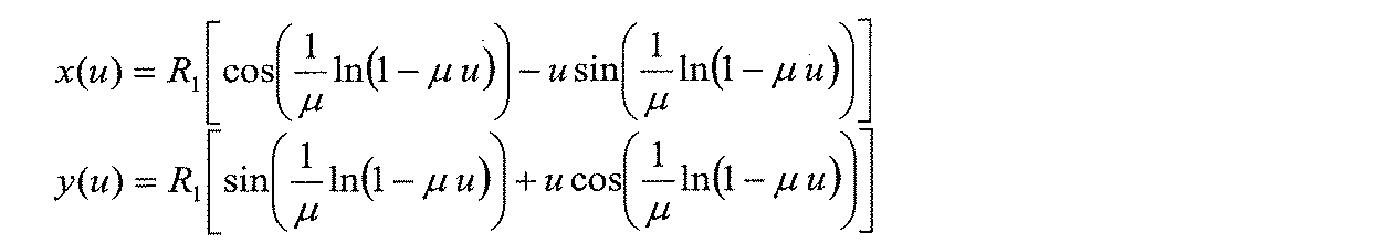
各ホイールの歯の部分aとbは、下記の式によって算出される:
注目すべきことは、上記の2つの関係が下記の結果を有することである:
x2+y2=R2 (1+u2).
It should be noted that the above two relationships have the following results:
x 2 + y 2 = R 2 (1 + u 2 ).
上記の式において、このベース半径Rは、前述したように決定される。他方では、uは、間隔[0,1/μ]の間で変化するパラメータである。uを変えることによって、この曲線は、通過される。各部分について、この変数uの初期の値(uini)は、対応する半径方向の座標が、d1(ホイール1について)およびd2(ホイール2について)に等しいように決定される。言い換えると、この値uiniは、ポイントP0に対応するように決定される。各歯の部分a1、b1、a2およびb2に対してRは異なるある値であるので、各歯並びに各部分aまたはbに対しても、同様に異なる初期変数uiniがある。各歯1または2の各部分aまたはbは、増加するか減少する仕方でuiniからuを変えることによってP0からスタートして延び、その結果、この輪郭は、「正しい方向において」(即ち部分aに対しては半径方向座標が減少し、部分bに対しては半径方向座標が増加する)延在する。
In the above formula, this base radius R is determined as described above. On the other hand, u is a parameter that varies between intervals [0, 1 / μ]. By changing u, this curve is passed. For each part, the initial value (u ini ) of this variable u is determined so that the corresponding radial coordinates are equal to d 1 (for wheel 1) and d 2 (for wheel 2). In other words, this value u ini is determined so as to correspond to the point P 0 . Since R is a different value for each tooth part a 1 , b 1 , a 2 and b 2 , there is a different initial variable u ini for each tooth and each part a or b as well. Each part a or b of each
更に、注目すべきことは、各ホイール1または2の輪郭の各部分aまたはbを、接触点が中心線上にある位置に移動させるために上式xとyによって得られたこの輪郭の回転を再び遂行することが、必要であることである。
Furthermore, it should be noted that the rotation of this contour obtained by the above equations x and y to move each portion a or b of the contour of each
このプロセスの第5のステップは、部分aとbの範囲(限界)を決定することである。 The fifth step in this process is to determine the range (limit) of parts a and b.
この間隔[0,1/μ]の間で初期値uiniから変数uを変えることによって、輪郭の部分aとbは、長くすることができる:即ち、部分bのインフィニティ(1/μ向かうuに対応する)まで、そして、部分aに対するこのベース半径R(限界値u = 0に対応する)まで。
これらの部分の範囲を決定する変数uの値ufinは、この選択された軸方向の中心距離の許容度を考慮して、この軸中心距離がたとえどうであっても、この2つの歯の接触が、歯のエッジの機能的なまたは有用な部分上に常にあるようにシンプルに選択される。当業者は、また、ある1つの歯の輪郭が、ホイールの次の歯の輪郭を侵さないことを確実にする。これを行うために、当業者は、この歯のエッジの傾斜角度αの選択と伝動装置の効率「ε」の選択の両方に従って行動することが可能である。
By changing the variable u from the initial value u ini during this interval [0, 1 / μ], the parts a and b of the contour can be lengthened: ie, the infinity of the part b (the u towards 1 / μ) Until this base radius R for the part a (corresponding to the limit value u = 0).
The value u fin of the variable u, which determines the range of these parts, takes into account the tolerance of the selected axial center distance, no matter what the axial center distance is, It is simply chosen so that the contact is always on a functional or useful part of the tooth edge. Those skilled in the art also ensure that one tooth profile does not violate the next tooth profile of the wheel. To do this, the person skilled in the art can act both according to the selection of the inclination angle α of the tooth edge and the selection of the transmission efficiency “ε”.
6.このプロセスの第6のステップは、フットおよびヘッドをこの歯に加えることである。 6). The sixth step in this process is to add a foot and head to the tooth.
上述の式は、ただ歯の輪郭の機能的な部分、即ち、別の歯との接触が起こることができるゾーンを記載するだけである。しかしながら、「機能的でない」ヘッドを追加することによって各歯を「閉じること」によって、また同様に隣接する歯のフットと連結されるフットを加えることによって噛み合いを完全なものとすることが必要である。これらの機能的でない部分が加えられるとき、噛み合いの間、機能的でない部分が機能的なゾーンを妨害するのを回避することが重要である。 The above formula only describes the functional part of the tooth profile, ie the zone in which contact with another tooth can occur. However, it is necessary to complete the engagement by "closing" each tooth by adding a "non-functional" head and by adding a foot that is also connected to the foot of the adjacent tooth. is there. When these non-functional parts are added, it is important to avoid the non-functional parts interfering with the functional zones during meshing.
数値例は下記の通り:
− 公称の軸中心距離d =2.958mm;
− 軸中心距離の間隔[dmin、 dmax] =[2.913mm、2.968mm];
− この2つのホイールの歯の数 z1 = 82およびz2 = 12;
− 摩擦係数μ= 0.2;
− 伝達されるべきトルクの断片(フラクション):ε = 0.966;
− 傾斜の角度:α = 30.5°.
上述の値から続く:
− 部分a1に対して、R = 1.932mm、uini = 0.894およびufin = 0.821;
− 部分a2に対して、R = 0.346mm、uini = 0.348およびufin = 0.013;
− 部分b1に対して、R = 2.447mm、uini = 0.348およびufin = 0.408;
− 部分b2に対して、R = 0.273mm、uini = 0.894およびufin = 1.162。
Numerical examples are as follows:
-Nominal axial center distance d = 2.958 mm;
-Axial center distance spacing [dmin, dmax] = [2.913 mm, 2.968 mm];
The number of teeth of the two wheels z1 = 82 and z2 = 12;
-Coefficient of friction μ = 0.2;
The fraction of torque to be transmitted (fraction): ε = 0.966;
-Angle of inclination: α = 30.5 °.
Continue from the above values:
- for the portion a 1, R = 1.932mm, u ini = 0.894 and u fin = 0.821;
- for the portion a 2, R = 0.346mm, u ini = 0.348 and u fin = 0.013;
-For part b 1 , R = 2.447 mm, u ini = 0.348 and u fin = 0.408;
- for the portion b 2, R = 0.273mm, u ini = 0.894 and u fin = 1.162.
図8A、8Bおよび8Cは、本発明による伝動装置における歯の駆動中の3つの連続したスナップショットである。図8Aは、この接触点がこの中心線の前に位置する瞬間に対応し、図8Cは、この接触点がこの中心線の後で位置する瞬間に対応する。この2つの間で、図8Bは、この中心線上にある接触点を示す。図8Aおよび8Cが示すように、相互の面の反応力はそれらの面に垂直でなくて、傾斜している。更に、相互の面の滑りの方向はこの嵌合点の両側で逆向きであるから、法線に対する力の方向の偏差も、またこの嵌合点の両側で逆方向にある。 8A, 8B and 8C are three consecutive snapshots during tooth drive in a transmission according to the present invention. FIG. 8A corresponds to the moment when this contact point is located before this center line, and FIG. 8C corresponds to the moment when this contact point is located after this center line. Between the two, FIG. 8B shows the contact point on this centerline. As FIGS. 8A and 8C show, the reaction forces of the mutual faces are not perpendicular to those faces but are inclined. Furthermore, since the slip direction of the mutual surfaces is opposite on both sides of the mating point, the deviation of the direction of force relative to the normal is also in the opposite direction on both sides of the mating point.
図8A、8Bおよび8Cは、再びこの接触点での力の方向が、2つのエッジの嵌合の全期間中、この交点P0に関係していることを確認可能とする。この特徴は、一定の伝達されるトルクを有することを可能にするための必要条件である。すでに説明したように、本発明による伝動装置の輪郭の1つの利点は、この2つのホイールの中心間の距離がこの理論的な基準と異なる場合であっても、トルクはほぼ一定の仕方で常に伝達されることである。 FIGS. 8A, 8B and 8C again make it possible to confirm that the direction of force at this contact point is related to this intersection point P 0 during the entire period of fitting of the two edges. This feature is a prerequisite for making it possible to have a constant transmitted torque. As already explained, one advantage of the profile of the transmission according to the invention is that the torque is always in a substantially constant manner, even if the distance between the centers of the two wheels is different from this theoretical criterion. Is to be communicated.
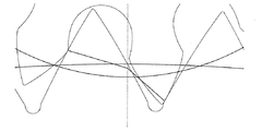
図8Bの様に、図9は、この接触点がこの中心線上に正確に位置している瞬間に対応する。図9において、この嵌合線は、破線で示されている。この円に対するコンボリュートのケースであったことに反して、本発明による伝動装置においては、この嵌合線は、この点P0で連結される2つの直線からなる部分から形成されることが分かろう。この嵌合線の方向が、あらゆる点でこの力の方向に対応することが、更に、理解されよう。最後に、この嵌合線と、接触している2つのエッジに共通である法線との間の角度は、摩擦係数のアークタンジェントに等しいことが明らかであろう。 Like FIG. 8B, FIG. 9 corresponds to the moment when this contact point is exactly located on this centerline. In FIG. 9, this fitting line is indicated by a broken line. Contrary to the case of the convolution with respect to this circle, in the transmission device according to the present invention, it can be seen that this fitting line is formed from a portion composed of two straight lines connected at this point P 0. Karo. It will be further understood that the direction of the mating line corresponds in all respects to the direction of this force. Finally, it will be apparent that the angle between this mating line and the normal common to the two edges in contact is equal to the arc tangent of the coefficient of friction.
図10A、10Bおよび10Cは、相互から3つの距離に位置した同じ対のホイールの嵌合をそれぞれ示している3つの部分的な模式図である。図11のグラフに関しては、図10A、10Bおよび10Cのそれぞれに対応している3つの異なる軸中心距離についての歯の駆動中に伝達されるトルクの変動を示す。連続線の曲線は、この公称軸中心距離に対応し、従って、図10Aに例示される状況に対応し、点(ドット)からなる曲線は図10Bに例示される状況に対応し、最後に、交互の点と線からなる曲線は、図10Cの状況に対応する。 FIGS. 10A, 10B and 10C are three partial schematic diagrams illustrating the fitting of the same pair of wheels located at three distances from each other. With respect to the graph of FIG. 11, the variation in torque transmitted during tooth drive for three different axial center distances corresponding to each of FIGS. 10A, 10B and 10C is shown. The continuous curve corresponds to this nominal axial center distance, and therefore corresponds to the situation illustrated in FIG. 10A, the curve consisting of dots (dots) corresponds to the situation illustrated in FIG. 10B, and finally A curve consisting of alternating points and lines corresponds to the situation of FIG. 10C.
図10Aに表される伝動装置において、この2つのホイールの中心間の距離は、この理論的な基準に対応する。この「理想的な」ケース(この中心線の通過の間)において、歯の間の接触点は、各々のホイールのエッジの部分aとb間の境界に正確に位置する。この場合、図11のある連続線の曲線が示すように、この伝達されたトルクは殆ど一定である。 In the transmission represented in FIG. 10A, the distance between the centers of the two wheels corresponds to this theoretical criterion. In this “ideal” case (during the passage of this centerline), the contact point between the teeth is precisely located at the boundary between the edge portions a and b of each wheel. In this case, as shown by a continuous curve in FIG. 11, the transmitted torque is almost constant.
図10Bの伝動装置において、この2つのホイールの中心間の距離は、理論的な基準(ノルム)より大きい。図10Cの伝動装置において、この2つのホイールの中心間の距離は、正規の距離より小さい。一続きの点(ドット)から形成され、また、交互の点と線から形成されてなる図11の曲線で示されるように、伝達されるトルクは、この軸中心距離が公称値から外れていて、中心線からの通過の周りからはなれているときでも、殆ど一定のままである。事実、ホイール間の距離が、公称の軸中心距離に対応しないときは、接触している2つの歯のフット部分とヘッド部分間のこの2つの転移点は決して正確には一致しない。これらの状態において、一方の有用な部分から他方の有用な部分への接触点の通過は、2つの歯に対して同時には起こらない。同時性のこの欠如は、この伝達されるトルクに一時的な変動を伴う。 In the transmission of FIG. 10B, the distance between the centers of the two wheels is larger than the theoretical standard (norm). In the transmission of FIG. 10C, the distance between the centers of the two wheels is smaller than the normal distance. As shown by the curve in FIG. 11 formed from a series of dots (dots) and formed from alternating points and lines, the transmitted torque is such that this axial center distance deviates from the nominal value. It remains almost constant even when separated from the passage from the centerline. In fact, when the distance between the wheels does not correspond to the nominal axial center distance, the two transition points between the two tooth foot portions and the head portion in contact will never exactly match. In these conditions, the passage of contact points from one useful part to the other useful part does not occur simultaneously for the two teeth. This lack of simultaneity is accompanied by temporary fluctuations in this transmitted torque.
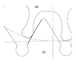
図12Aおよび12Bは、本発明の第2の実施例による伝動装置における歯の駆動中の連続したスナップショットである。この第2の実施例によれば、1つの歯のエッジの機能的な部分は、たった1つの輪郭部分から成るものであって、図7〜11に例示の実施例におけるような2つの輪郭部分からなるものではない。 12A and 12B are successive snapshots during tooth drive in a transmission according to a second embodiment of the present invention. According to this second embodiment, the functional part of one tooth edge consists of only one contour part, and two contour parts as in the embodiment illustrated in FIGS. It does not consist of
駆動輪がホイール101で、被駆動輪がホイール102であると仮定すると、図12Aおよび12Bには2つの歯はただ中心線の後で接触するだけであることが見てとれよう。
これらの状態において、上で採用されたのと同じ約束が守られるならば、この摩擦係数「μ」は常に正であると言うことができる。事実、これらエッジ間の接触は、この中心線の後で、常に起こる(しかしながら、これらのホイールが他の方向に回ったならば、ホイール102が駆動輪となり、ホイール101が被駆動輪となる。すると、エッジ間の接触は、常に中心線の前で生じ、後で生じるのではないことが知れよう)。
Assuming that the driving wheel is
In these conditions, it can be said that this coefficient of friction “μ” is always positive if the same promises adopted above are observed. In fact, contact between these edges always occurs after this centerline (however, if these wheels turn in the other direction,
本発明のこの第2の実施例の効果は、伝達されるトルクの一時的な変動が回避されるということであり、この一時的な変動は本発明の第1実施例に関して上述した同時性の欠如と関係している。 The effect of this second embodiment of the present invention is that a temporary variation in the transmitted torque is avoided, which is the same as described above with respect to the first embodiment of the present invention. Related to lack.
提案された本発明は、理論的には、正確に変動零(0%)を達成することを可能にする。しかしながら、それにもかかわらず、軸中心距離が正規でないとき、または摩擦係数が一方の部分から他の部分に変わり得るので、または、時間の経過の中で、変動の観察が予想される。しかしながら、出願人はこれらの変動は現行の輪郭のものより明らかに少ないことを算出し得た。 The proposed invention theoretically makes it possible to achieve exactly zero variation (0%). However, fluctuations are nevertheless expected when the axial center distance is not normal, or because the coefficient of friction can change from one part to the other, or over time. However, the applicant could calculate that these variations are clearly less than those of the current profile.
Claims (3)
Applications Claiming Priority (2)
| Application Number | Priority Date | Filing Date | Title |
|---|---|---|---|
| EP10190884.6A EP2453321B1 (en) | 2010-11-11 | 2010-11-11 | Constant torque gear contour |
| EP10190884.6 | 2010-11-11 |
Publications (2)
| Publication Number | Publication Date |
|---|---|
| JP2012102877A true JP2012102877A (en) | 2012-05-31 |
| JP5520278B2 JP5520278B2 (en) | 2014-06-11 |
Family
ID=43920113
Family Applications (1)
| Application Number | Title | Priority Date | Filing Date |
|---|---|---|---|
| JP2011247198A Expired - Fee Related JP5520278B2 (en) | 2010-11-11 | 2011-11-11 | Profile gear with constant torque |
Country Status (6)
| Country | Link |
|---|---|
| US (1) | US8833192B2 (en) |
| EP (1) | EP2453321B1 (en) |
| JP (1) | JP5520278B2 (en) |
| CN (1) | CN102563007B (en) |
| HK (1) | HK1173204A1 (en) |
| RU (1) | RU2578574C2 (en) |
Cited By (3)
| Publication number | Priority date | Publication date | Assignee | Title |
|---|---|---|---|---|
| JP2017223661A (en) * | 2016-05-12 | 2017-12-21 | ロレックス・ソシエテ・アノニムRolex Sa | Gearwheel for clock movement |
| WO2017221897A1 (en) * | 2016-06-23 | 2017-12-28 | シチズン時計株式会社 | Wheel train mechanism of clock |
| KR20200112116A (en) * | 2019-03-21 | 2020-10-05 | 엘에스엠트론 주식회사 | Transmission for agricultural working machine with improved lubricating characteristic |
Families Citing this family (2)
| Publication number | Priority date | Publication date | Assignee | Title |
|---|---|---|---|---|
| JP6099649B2 (en) * | 2011-08-24 | 2017-03-22 | ツェットエフ ウィンド パワー アントワープ エヌ ヴイZf Wind Power Antwerpen N.V. | Gear transmission system |
| JP2020144117A (en) | 2019-03-01 | 2020-09-10 | ロレックス・ソシエテ・アノニムRolex Sa | Horological gearing |
Citations (3)
| Publication number | Priority date | Publication date | Assignee | Title |
|---|---|---|---|---|
| DE1960927A1 (en) * | 1969-12-04 | 1971-06-16 | Uhren Feingeraete Forsch | Tooth profiles for constant torque transmission for translations from slow to fast with small numbers of drive teeth, as well as methods for their calculation |
| JP2002227967A (en) * | 2001-02-01 | 2002-08-14 | Seiko Epson Corp | Gear, power transmission device equipped with the gear, equipment equipped with the power transmission device and manufacturing method of the gear |
| CH699679A2 (en) * | 2008-10-02 | 2010-04-15 | Montres Breguet Sa | Gear train e.g. finishing gear train, for watch, has toothed elements provided with gear teeth, where each tooth is composed of N coaxial toothed rings that are angularly offset with respect to each other by fraction of pitch of teeth |
Family Cites Families (9)
| Publication number | Priority date | Publication date | Assignee | Title |
|---|---|---|---|---|
| US3220279A (en) * | 1963-12-16 | 1965-11-30 | Exxon Production Research Co | Gear tooth system |
| US3631736A (en) * | 1969-12-29 | 1972-01-04 | Illinois Tool Works | Gear tooth form |
| US4640149A (en) * | 1983-03-04 | 1987-02-03 | The Boeing Company | High profile contact ratio, non-involute gear tooth form and method |
| JPH0784896B2 (en) * | 1986-11-05 | 1995-09-13 | 株式会社ハーモニック・ドライブ・システムズ | Flexible mesh type gear device |
| US5546824A (en) * | 1993-10-22 | 1996-08-20 | Imo Industries Inc. | Visual method and apparatus for adjusting gears and pinions |
| US6902507B2 (en) * | 2002-04-11 | 2005-06-07 | Richard N. Ballard | Roller cam assembly |
| FR2867542B1 (en) * | 2004-03-12 | 2007-04-20 | Centre Nat Rech Scient | DENTAL ORGAN AND GEAR RELATING THERETO |
| CN101109436B (en) * | 2006-07-21 | 2011-02-16 | 北京交通大学 | Speed increasing or speed reducing gear pair adapted for power transmission |
| US20080115610A1 (en) * | 2006-11-21 | 2008-05-22 | Deere & Company | Tooth profile for a high contact ratio spur gear |
-
2010
- 2010-11-11 EP EP10190884.6A patent/EP2453321B1/en active Active
-
2011
- 2011-11-09 US US13/292,565 patent/US8833192B2/en active Active
- 2011-11-10 RU RU2011145774/12A patent/RU2578574C2/en not_active IP Right Cessation
- 2011-11-11 CN CN201110459536.6A patent/CN102563007B/en not_active Expired - Fee Related
- 2011-11-11 JP JP2011247198A patent/JP5520278B2/en not_active Expired - Fee Related
-
2013
- 2013-01-10 HK HK13100385.8A patent/HK1173204A1/en not_active IP Right Cessation
Patent Citations (3)
| Publication number | Priority date | Publication date | Assignee | Title |
|---|---|---|---|---|
| DE1960927A1 (en) * | 1969-12-04 | 1971-06-16 | Uhren Feingeraete Forsch | Tooth profiles for constant torque transmission for translations from slow to fast with small numbers of drive teeth, as well as methods for their calculation |
| JP2002227967A (en) * | 2001-02-01 | 2002-08-14 | Seiko Epson Corp | Gear, power transmission device equipped with the gear, equipment equipped with the power transmission device and manufacturing method of the gear |
| CH699679A2 (en) * | 2008-10-02 | 2010-04-15 | Montres Breguet Sa | Gear train e.g. finishing gear train, for watch, has toothed elements provided with gear teeth, where each tooth is composed of N coaxial toothed rings that are angularly offset with respect to each other by fraction of pitch of teeth |
Cited By (9)
| Publication number | Priority date | Publication date | Assignee | Title |
|---|---|---|---|---|
| JP2017223661A (en) * | 2016-05-12 | 2017-12-21 | ロレックス・ソシエテ・アノニムRolex Sa | Gearwheel for clock movement |
| JP7106250B2 (en) | 2016-05-12 | 2022-07-26 | ロレックス・ソシエテ・アノニム | Gears for watch movements |
| WO2017221897A1 (en) * | 2016-06-23 | 2017-12-28 | シチズン時計株式会社 | Wheel train mechanism of clock |
| WO2017221522A1 (en) * | 2016-06-23 | 2017-12-28 | シチズン時計株式会社 | Wheel train mechanism of clock |
| JPWO2017221897A1 (en) * | 2016-06-23 | 2019-04-11 | シチズン時計株式会社 | Clock train mechanism |
| EP3447589A4 (en) * | 2016-06-23 | 2019-11-27 | Citizen Watch Co., Ltd. | Wheel train mechanism of clock |
| US10895844B2 (en) | 2016-06-23 | 2021-01-19 | Citizen Watch Co., Ltd. | Gear train mechanism of timepiece |
| KR20200112116A (en) * | 2019-03-21 | 2020-10-05 | 엘에스엠트론 주식회사 | Transmission for agricultural working machine with improved lubricating characteristic |
| KR102560499B1 (en) | 2019-03-21 | 2023-07-28 | 엘에스엠트론 주식회사 | Transmission for agricultural working machine with improved lubricating characteristic |
Also Published As
| Publication number | Publication date |
|---|---|
| US8833192B2 (en) | 2014-09-16 |
| US20120118093A1 (en) | 2012-05-17 |
| CN102563007A (en) | 2012-07-11 |
| EP2453321A1 (en) | 2012-05-16 |
| HK1173204A1 (en) | 2013-05-10 |
| JP5520278B2 (en) | 2014-06-11 |
| EP2453321B1 (en) | 2015-09-09 |
| CN102563007B (en) | 2015-07-15 |
| RU2578574C2 (en) | 2016-03-27 |
Similar Documents
| Publication | Publication Date | Title |
|---|---|---|
| JP5520278B2 (en) | Profile gear with constant torque | |
| US8020464B2 (en) | Gear pairs for power transmission in speed increaser or reducer and methods of forming the same | |
| JP4838307B2 (en) | Gear drive | |
| US9562601B2 (en) | Gear transmission system | |
| US10409222B2 (en) | Gearwheel for clock movement | |
| CN104204617A (en) | Gear mechanism and manufacturing method of gear mechanism | |
| WO2004016971A1 (en) | Gear member for power transmission | |
| CN102374273A (en) | Tooth profile design of dual-pressure angle involute helical tooth externally-meshed cylindrical gear | |
| CN104520069A (en) | Gears and manufacturing method thereof | |
| TWI518266B (en) | Harmonic speed reduction mechanism | |
| US7870785B2 (en) | Positive displacement flowmeter | |
| US10895844B2 (en) | Gear train mechanism of timepiece | |
| US1074362A (en) | Intermittent-gear mechanism. | |
| JP3669273B2 (en) | GEAR, POWER TRANSMISSION DEVICE INCLUDING THIS GEAR, DEVICE HAVING THIS POWER TRANSMISSION DEVICE, AND GEAR MANUFACTURING METHOD | |
| Maláková et al. | Gear shape optimization for non-circular gearing | |
| CN110059287B (en) | Method for calculating meshing stiffness of internal gear pair by considering prolonged meshing and gear ring flexibility | |
| JP2005257056A (en) | Silent chain transmission device | |
| RU87112U1 (en) | HYPERBOLOID GEAR | |
| CN113280081A (en) | Non-sliding parallel axis gear mechanism with separable center distance | |
| Rao et al. | Spur Gears | |
| JP2015129571A (en) | Double-helical gear |
Legal Events
| Date | Code | Title | Description |
|---|---|---|---|
| A131 | Notification of reasons for refusal |
Free format text: JAPANESE INTERMEDIATE CODE: A131 Effective date: 20130702 |
|
| A601 | Written request for extension of time |
Free format text: JAPANESE INTERMEDIATE CODE: A601 Effective date: 20131002 |
|
| A602 | Written permission of extension of time |
Free format text: JAPANESE INTERMEDIATE CODE: A602 Effective date: 20131007 |
|
| A601 | Written request for extension of time |
Free format text: JAPANESE INTERMEDIATE CODE: A601 Effective date: 20131105 |
|
| A602 | Written permission of extension of time |
Free format text: JAPANESE INTERMEDIATE CODE: A602 Effective date: 20131108 |
|
| A601 | Written request for extension of time |
Free format text: JAPANESE INTERMEDIATE CODE: A601 Effective date: 20131202 |
|
| A602 | Written permission of extension of time |
Free format text: JAPANESE INTERMEDIATE CODE: A602 Effective date: 20131205 |
|
| A521 | Written amendment |
Free format text: JAPANESE INTERMEDIATE CODE: A523 Effective date: 20131218 |
|
| TRDD | Decision of grant or rejection written | ||
| A01 | Written decision to grant a patent or to grant a registration (utility model) |
Free format text: JAPANESE INTERMEDIATE CODE: A01 Effective date: 20140401 |
|
| A61 | First payment of annual fees (during grant procedure) |
Free format text: JAPANESE INTERMEDIATE CODE: A61 Effective date: 20140404 |
|
| R150 | Certificate of patent or registration of utility model |
Ref document number: 5520278 Country of ref document: JP Free format text: JAPANESE INTERMEDIATE CODE: R150 |
|
| R250 | Receipt of annual fees |
Free format text: JAPANESE INTERMEDIATE CODE: R250 |
|
| LAPS | Cancellation because of no payment of annual fees |