JP2012102368A - Device for wiping hot-dip plated wire, and method for wiping hot-dip plated wire - Google Patents
Device for wiping hot-dip plated wire, and method for wiping hot-dip plated wire Download PDFInfo
- Publication number
- JP2012102368A JP2012102368A JP2010251946A JP2010251946A JP2012102368A JP 2012102368 A JP2012102368 A JP 2012102368A JP 2010251946 A JP2010251946 A JP 2010251946A JP 2010251946 A JP2010251946 A JP 2010251946A JP 2012102368 A JP2012102368 A JP 2012102368A
- Authority
- JP
- Japan
- Prior art keywords
- hot
- wiping
- wire
- hole
- metal
- Prior art date
- Legal status (The legal status is an assumption and is not a legal conclusion. Google has not performed a legal analysis and makes no representation as to the accuracy of the status listed.)
- Withdrawn
Links
Images


Landscapes
- Coating With Molten Metal (AREA)
Abstract
Description
本発明は、溶融めっき線表面の余剰溶融めっき金属を除去するためのワイピング装置及びワイピング方法に関するものである。 The present invention relates to a wiping apparatus and a wiping method for removing excess hot dip plated metal on the surface of a hot dip wire.
腐食環境下で使用される金属線には、耐食性を付与するため、表面に溶融金属めっきが施される。金属線としては、鉄線、鋼線や、非鉄金属製線、合金製線が挙げられる。また、溶融金属めっきとして、溶融亜鉛めっき、および任意の割合でAlを含有する合金亜鉛めっきなどを挙げることができる。 A metal wire used in a corrosive environment is subjected to molten metal plating on the surface in order to impart corrosion resistance. Examples of metal wires include iron wires, steel wires, non-ferrous metal wires, and alloy wires. Further, examples of the hot metal plating include hot dip galvanizing and galvanizing alloy containing Al at an arbitrary ratio.
金属線の溶融金属めっきにおいては、金属線を溶融めっき金属浴に浸漬し、金属線の表面に溶融めっき金属を付着させ、その後に引き上げ、金属線表面に付着するめっき金属層の厚さを調整する。 In molten metal plating of metal wires, immerse the metal wires in a hot-dip metal bath, attach the hot-dip metal to the surface of the metal wire, and then pull up to adjust the thickness of the plated metal layer attached to the surface of the metal wire To do.
金属線表面に比較的厚めっきを施す場合には、溶融めっき浴から金属線を引き上げるに際して垂直上方に引き上げ、金属線表面における溶融めっき金属の付着量を金属線の引上げ速度によって調整することができる。引き上げ速度が速いほど溶融めっき金属の残存量が多くなり、めっき厚を厚くすることができる。厚めっきの範疇でめっき厚を比較的薄くしようとする場合は、金属線の引き上げ速度を遅くする。さらにめっき厚を薄くする場合について、特許文献1には絞りダイスを用いて溶融金属の付着量を制御する方法が開示されている。絞りダイスの材質としてセラミックスが好ましいとしている。また、特許文献2においては、2枚のU字形板片によって中央に四角の孔形を形成し、この四角の孔形に溶融めっき層から引き上げられた線を通し、溶融めっき金属を孔形によって絞った後、表面張力により線の周囲にめっき金属が均一に厚く被覆されるとしている。U字形板材には溶融金属と合金または反応しがたい金属が用いられる。特許文献3には、ガスワイピングによって付着する溶融めっき厚を制御する方法が開示されている。これら特許文献1〜3に記載のものは、めっき厚み30μm前後以上の比較的厚めっきにおけるめっき厚制御方法として適用することができる。
When relatively thick plating is applied to the surface of the metal wire, when the metal wire is pulled up from the hot dipping bath, the metal wire is pulled up vertically, and the amount of hot-dip metal deposited on the surface of the metal wire can be adjusted by the pulling speed of the metal wire. . The higher the pulling speed, the greater the remaining amount of hot-dip plated metal and the thicker the plating thickness. When attempting to make the plating thickness relatively thin in the category of thick plating, the pulling speed of the metal wire is slowed down. Furthermore, regarding the case of reducing the plating thickness,
金属線の溶融金属めっきにおいて10〜20μm厚の薄めっきを施す場合については、絞りダイスを用い、絞りダイスのダイス径をめっき後のめっき線直径と等しくすることにより、余剰の溶融めっき金属を除去する方法が知られている(特許文献4、5)。しかし、これら方法では、操業を開始する前に予め金属線直径にほぼ等しい絞りダイス孔中に金属線を通しておく必要があり、作業性が劣る。また、金属線と絞りダイス孔とのわずかな隙間に異物が挟まってめっき線表面に疵を付ける恐れがあり、さらにめっきを施す前の芯線にはコイルを接続する際の溶接部、突起、バリ等が存在し、必ずしも断面形状が一定していない。そのため、特に薄めっきの溶融めっき線を製造する際には、断線の発生も懸念される。 In the case of thin metal plating with a thickness of 10 to 20 μm in molten metal plating of metal wire, excess hot-dipped metal is removed by using a drawing die and making the die diameter of the drawing die equal to the plating wire diameter after plating. The method of doing is known (patent documents 4 and 5). However, in these methods, it is necessary to pass a metal wire through a drawing die hole that is approximately equal to the diameter of the metal wire before starting the operation, and workability is inferior. In addition, foreign matter may get caught in the slight gap between the metal wire and the drawing die hole, and the surface of the plated wire may be wrinkled. Further, the core wire before plating is welded, projected, and burred when the coil is connected. Etc., and the cross-sectional shape is not necessarily constant. Therefore, when manufacturing a thin hot-dip galvanized wire, there is a concern about the occurrence of disconnection.
めっきを施す金属線と溶融めっき金属浴が接触したとき、金属線を構成する金属とめっき金属とが金属間化合物を形成することがある。例えば、金属線として鉄線を用い、めっき金属として亜鉛を用いた場合、ζ相(FeZn18)、δ1相(FeZn7)などの金属間化合物が形成される。金属線をメッキ浴に浸漬中に金属線表面に金属間化合物層が形成され、溶融めっき浴から引き上げたときには、金属線の表面にしかるべき厚さで固体の金属間化合物層が形成され、さらにその表面に溶融しためっき金属が付着している。そこで、薄めっきを施す方法として、めっき浴中で金属線表面に金属間化合物層を形成させ、めっき浴から引き上げ、溶融しためっき金属層をしごき取る方法が用いられる。しごき取った後には固体の金属間化合物層が残り、この金属間化合物層がめっき層となる。金属間化合物層の厚さを制御することにより、薄めっきの場合におけるめっき層厚さを正確に制御することが可能である。溶融金属をしごき取る方法としては、溶融めっき浴から引き上げられる金属線にワイヤ、グラスウール、耐熱性樹脂繊維等からなる耐熱材料、例えばアラミド繊維製ヤーン等を巻き付けるか、これら材料からなるパッドを対向させてめっき線を挟み、付着した溶融金属をしごき取る方法が採用されている(特許文献6参照)。特にパッド方式は、通線速度を上げることが可能であることから、薄めっきの溶融めっき線の製造に適している。 When the metal wire to be plated comes into contact with the hot dipped metal bath, the metal constituting the metal wire and the plated metal may form an intermetallic compound. For example, when an iron wire is used as the metal wire and zinc is used as the plating metal, an intermetallic compound such as ζ phase (FeZn 18 ), δ 1 phase (FeZn 7 ) is formed. When the metal wire is immersed in the plating bath, an intermetallic compound layer is formed on the surface of the metal wire, and when it is pulled out from the hot dipping bath, a solid intermetallic compound layer is formed on the surface of the metal wire with an appropriate thickness. Molten plating metal adheres to the surface. Therefore, as a method of performing thin plating, a method of forming an intermetallic compound layer on the surface of a metal wire in a plating bath, pulling up from the plating bath, and scoring the molten plated metal layer is used. After squeezing, a solid intermetallic compound layer remains, and this intermetallic compound layer becomes a plating layer. By controlling the thickness of the intermetallic compound layer, it is possible to accurately control the thickness of the plating layer in the case of thin plating. As a method of scoring the molten metal, a heat resistant material made of wire, glass wool, heat resistant resin fiber, etc., such as an aramid fiber yarn, is wound around a metal wire pulled up from a hot dipping bath, or a pad made of these materials is made to face. A method is adopted in which the plated wire is sandwiched and the adhered molten metal is scraped off (see Patent Document 6). In particular, the pad method is suitable for manufacturing a thin-plated hot-dip wire because it can increase the line speed.
溶融めっき浴中で金属線表面に金属間化合物層を形成させ、引き上げた金属線の表面に耐熱性樹脂繊維等からなるパッドを押し当てて溶融金属層をしごき取る前記方法において、パッドに使用される例えばアラミド繊維は、長時間ワイピングを継続していると、熱によって炭化し、強度が低下して、パッドから脱落することがある。そのため、パッドの一部が溶融めっき線に付着し、表面品質を劣化させるという問題がある。 In the above method, an intermetallic compound layer is formed on the surface of a metal wire in a hot dipping bath, and a pad made of a heat-resistant resin fiber or the like is pressed against the surface of the pulled-up metal wire to scrub the molten metal layer. For example, when wiping is continued for a long time, an aramid fiber may be carbonized by heat to decrease in strength and fall off the pad. Therefore, there is a problem that a part of the pad adheres to the hot dip wire and deteriorates the surface quality.
本発明は、めっき浴から引き上げた溶融めっき線の表面から余剰の溶融めっき金属をしごき取るに際し、しごき取りに用いるワイピング部材の劣化がなく、長時間にわたって安定してワイピングを可能にする、溶融めっき線のワイピング装置及び溶融めっき線のワイピング方法を提供することを目的とする。 The present invention provides hot dip wiping that can be stably wiped for a long time without deterioration of the wiping member used for wiping when the hot dip plating metal is scraped from the surface of the hot dip wire pulled up from the plating bath. An object of the present invention is to provide a wire wiping apparatus and a hot dip wiping method.
即ち、本発明の要旨とするところは以下のとおりである。
(1)溶融めっき線表面の余剰溶融めっき金属を除去するためのワイピング装置であって、該ワイピング装置はワイピング部材7を有し、ワイピング部材7は溶融めっき線5が通過する貫通孔8を有し、貫通孔8の軸方向と垂直な断面内で貫通孔に内接する円(以下「内接円10」という。)の半径がめっき線半径よりも0.02mm以上大きく、貫通孔8の表面9は金属(以下「ワイピング部材金属」という。)であり、ワイピング部材金属は、平面状のワイピング部材金属に塩化アンモニウム亜鉛を塗布した上で溶融めっき金属を接触させたときの濡れ角度が90°以下となる金属であることを特徴とする溶融めっき線のワイピング装置。
(2)貫通孔8の軸方向一部又は全部において軸方向と垂直な断面内で、貫通孔の周方向いずれの部分も貫通孔表面9と内接円10の中心11との距離がめっき線半径+3.0mm以下であることを特徴とする上記(1)に記載の溶融めっき線のワイピング装置。
(3)ワイピング部材金属として、前記濡れ角度による規定に代え、ステンレス鋼を除く鋼を用いることを特徴とする上記(1)又は(2)に記載の溶融めっき線のワイピング装置。
(4)ワイピング部材7は分割面18に沿って複数に分割可能であり、分割面18は貫通孔8を通過することを特徴とする上記(1)乃至(3)のいずれかに記載の溶融めっき線のワイピング装置。
(5)分割された複数のワイピング部材は、250N以下の押付力で相互に押し付けられていることを特徴とする上記(4)に記載の溶融めっき線のワイピング装置。
(6)貫通孔8の長さが5〜150mmであることを特徴とする上記(1)乃至(5)のいずれかに記載の溶融めっき線のワイピング装置。
(7)さらにストッパー6を有し、ワイピング部材7の貫通孔8に溶融めっき線5を貫通させたときに、ストッパー6はワイピング部材7の下流側に位置し、ワイピング部材7がストッパー6に当接するように配置されていることを特徴とする上記(1)乃至(6)のいずれかに記載の溶融めっき線のワイピング装置。
(8)溶融めっき線のめっき層に占める金属間化合物の割合が面積率で90%以上である溶融めっき線のワイピングに用いることを特徴とする上記(1)乃至(7)のいずれかに記載の溶融めっき線のワイピング装置。
(9)上記(1)乃至(7)のいずれかに記載の溶融めっき線のワイピング装置を用い、ワイピング部材7の貫通孔表面9に酸化防止剤を塗布し、ワイピング部材の貫通孔8に、溶融めっき浴を通過した溶融めっき線5を通過させることを特徴とする溶融めっき線のワイピング方法。
(10)ワイピングを行った上で冷却した溶融めっき線のめっき層について、金属間化合物が占める割合が面積率で90%以上とすることを特徴とする上記(9)に記載の溶融めっき線のワイピング方法。
(11)めっきを施す芯線1が鋼線であり、めっき金属が亜鉛であることを特徴とする上記(10)に記載の溶融めっき線のワイピング方法。
That is, the gist of the present invention is as follows.
(1) A wiping device for removing surplus hot dip plated metal on the surface of a hot dipped wire, the wiping device having a
(2) The distance between the through-
(3) The hot dip wiping apparatus for hot-dip plated wire as described in (1) or (2) above, wherein steel other than stainless steel is used as the wiping member metal instead of the prescription based on the wetting angle.
(4) The melting according to any one of (1) to (3) above, wherein the
(5) The galvanized wire wiping apparatus according to (4), wherein the plurality of divided wiping members are pressed against each other with a pressing force of 250 N or less.
(6) The hot-dip wiping device for hot-dip plated wire as described in any one of (1) to (5) above, wherein the length of the
(7) A
(8) The method according to any one of (1) to (7), which is used for wiping a hot-dip plated wire in which a ratio of an intermetallic compound in a plating layer of the hot-dip wire is 90% or more in area ratio Wiping equipment for hot-dip plated wire.
(9) Using the hot dip wiping apparatus according to any one of (1) to (7) above, an antioxidant is applied to the through
(10) About the plating layer of the hot-dip plated wire cooled after wiping, the ratio of the intermetallic compound is 90% or more in area ratio. Wiping method.
(11) The galvanized wire wiping method according to (10) above, wherein the
本発明は、溶融めっき線表面の余剰溶融めっき金属を除去するためのワイピング装置において、ワイピング部材は溶融めっき線が通過する貫通孔を有し、貫通孔の大きさを溶融めっき線よりも大きくし、貫通孔の表面は溶融めっき金属と濡れ性の良好な金属を用いるので、貫通孔と溶融めっき線との間の隙間に金属間化合物層が形成され、この金属間化合物層によって溶融めっき線の表面から余剰の溶融めっき金属をしごき取るので、しごき取りに用いるワイピング部材の劣化がなく、長時間にわたって安定してワイピングを可能にする。 The present invention relates to a wiping apparatus for removing surplus molten plated metal on the surface of a hot dip plated wire, wherein the wiping member has a through hole through which the hot dip plated wire passes, and the size of the through hole is made larger than that of the hot dip plated wire. The surface of the through-hole uses a hot-dip metal and a metal with good wettability, so an intermetallic compound layer is formed in the gap between the through-hole and the hot-dip plated wire. Since excess hot-dip plated metal is scraped off from the surface, the wiping member used for scraping is not deteriorated, and stable wiping is possible for a long time.
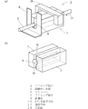
本発明のワイピング装置は、図1に示すような金属線の溶融めっきラインで使用することができる。芯線1を溶融めっき浴4に浸漬し、シンカー3を経て溶融めっき浴4から引き上げる。溶融めっき浴から引き上げる金属線(溶融めっき線5)を垂直方向に引き上げる必要がないので、図1に示すように溶融めっき線5を溶融めっき浴4から斜めに引き上げることが可能となる。
The wiping apparatus of the present invention can be used in a hot dipping line for metal wires as shown in FIG. The
本発明は、薄めっきを施す方法として、めっき浴中で芯線の表面に金属間化合物層を形成させ、溶融めっき浴から引き上げ、表面の溶融めっき金属層をしごき取るめっき方法を適用対象とする。 The present invention is applicable to a plating method in which an intermetallic compound layer is formed on the surface of a core wire in a plating bath, pulled out from the hot dipping bath, and the hot dipped metal layer is squeezed out as a method of performing thin plating.
図2、3に基づいて本発明を説明する。本発明のワイピング装置はワイピング部材7を有し、ワイピング部材7は溶融めっき線5が通過する貫通孔8を有し、貫通孔の表面9は金属(ワイピング部材金属)である。図1に示すように溶融めっき浴4を通過した溶融めっき線5が、図2、3に示すようにワイピング部材7の貫通孔8を通過する際に、図6に示すように溶融めっき線5の金属間化合物層12のさらに表面に付着した溶融めっき金属14がしごき取られ、通過後のめっき線表面には金属間化合物層12が残存し、この金属間化合物層12が溶融めっき線5のめっき層となる。
The present invention will be described with reference to FIGS. The wiping device of the present invention has a wiping
ワイピング部材7の貫通孔8の軸方向と垂直な断面内で貫通孔に内接する円(以下単に「内接円10」ともいう。)の半径30をめっき線半径31よりも0.02mm以上大きくする。本発明において貫通孔に内接する円(内接円10)とは、貫通孔内部に円の全体が収まるような円のうちで半径が最も大きな円を意味する。図4(a)は貫通孔8の断面形状が正方形である場合の内接円10が記されている。図4(b)に示すように貫通孔8の断面形状が真円の場合には貫通孔形状と内接円10が一致する。まためっき線半径31とは目標とするめっき線の半径をいう。芯線1に金属間化合物層12が形成され、表面の溶融めっき金属をしごき取った後のめっき線の半径を意味する。従来からワイピングのために用いられていた絞りダイスは、ダイス孔形の内径をめっき線の径と等しくし、めっき線表面の余剰の溶融金属を絞りダイスによって除去していた。本発明のワイピング部材の貫通孔は、上述のとおり貫通孔に内接する円(内接円10)の半径がめっき線半径よりも大きいので、このままではめっき線表面の溶融めっき層をしごき取ることができない。本発明において、ワイピング部材の貫通孔8の表面9が金属(ワイピング部材金属)であり、このワイピング部材金属として溶融めっき浴と濡れ性が良好である金属を選択する。濡れ性が良好とは、平面状の金属表面を活性とした上で溶融めっき金属を接触させたとき、濡れ角度が90°以下となる場合をいう。金属表面を活性化するに当たって、ろう接などで通常に用いられるフラックスによって容易に活性化する金属でないと、容易に用いることができない。本発明においてはフラックスとして塩化アンモニウム亜鉛を基準とし、このフラックスを塗布した上で溶融めっき金属を接触させたときに濡れ性が良好になる金属であればワイピング部材金属として良好に使用することができる。
A
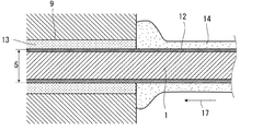
溶融めっき浴を通過した溶融めっき線がワイピング部材の貫通孔を通過するとき、溶融めっき線表面に付着している溶融めっき金属がワイピング部材金属と接触し、溶融めっき金属とワイピング部材金属とは濡れ性が良好であるため、両者は付着しあって濡れることとなる。溶融めっき線の芯線と溶融めっき金属との界面には金属間化合物層が形成されている。溶融めっき線が貫通孔を通過し始めた当初は、溶融めっき線と貫通孔との間の隙間には溶融めっき金属が充填されているが、若干の時間が経過した後、溶融めっき線と貫通孔との間の隙間は金属間化合物によって置き換わっていく。通過する溶融めっき線の表面に形成されている金属間化合物の一部が貫通孔内に残って徐々に堆積していくものと考えられる。また、ワイピング部材金属として溶融めっき金属と金属間化合物を形成するような金属を選択すれば、ワイピング部材金属側からも溶融めっき金属中に金属間化合物が供給されることとなる。このようにして溶融めっき線と貫通孔との間の隙間が金属間化合物によって置き換わると、図5に示すように、溶融めっき線5と貫通孔8との間の隙間に充満し貫通孔側に被着した金属間化合物層13が、溶融めっき線表面に形成された金属間化合物層12と擦過して擦り合わされ、貫通孔側の金属間化合物層13の表面が平滑な円筒形状を形成し、円筒の内径が溶融めっき線の金属間化合物層12の表面外径に等しくなる。その結果、図6に示すように、貫通孔側に被着した金属間化合物層13が、溶融めっき線の表面に被着している溶融めっき金属14をしごき取る機能を発揮するようになる。こうして、貫通孔8を通過した溶融めっき線5の表面においては、貫通孔に入るまでに線の表面に形成された金属間化合物層12が残り、その上に被着していた溶融めっき金属層14が除去され、所定の厚みのめっき層が形成された溶融めっき線となっている。
When the hot-dip plating wire that has passed through the hot-dip plating bath passes through the through hole of the wiping member, the hot-dip plating metal adhering to the hot-dip plating wire surface comes into contact with the wiping member metal, and the hot-dip plating metal and the wiping member metal are wet. Since the property is good, both adhere to each other and get wet. An intermetallic compound layer is formed at the interface between the core wire of the hot dipped wire and the hot dipped metal. When the hot-dip plated wire started to pass through the through-hole, the gap between the hot-dip plated wire and the through-hole was filled with hot-dip plated metal. The gap between the holes is replaced by the intermetallic compound. It is considered that a part of the intermetallic compound formed on the surface of the passing hot-dip wire remains in the through hole and gradually accumulates. Further, if a metal that forms an intermetallic compound with a hot dip metal is selected as the wiping member metal, the intermetallic compound is supplied into the hot dip metal from the wiping member metal side. When the gap between the hot dipped wire and the through hole is replaced by the intermetallic compound in this way, the gap between the hot dipped
本発明において重要なことは、貫通孔の表面9を形成するワイピング部材金属と溶融めっき金属とが濡れることである。濡れ性が良好でないと、溶融めっき線表面の溶融めっき金属は貫通孔内に留まることがなく、従って貫通孔内に金属間化合物層13が形成されてしごき取りの機能を発揮することもない。例えば、貫通孔表面を形成する材料がセラミックスであった場合にはしごき取り機能が発揮されることはない。また、貫通孔表面が金属であっても、溶融めっき金属と濡れない限りはしごき取り機能は発揮されない。溶融めっき線を通過させる前に貫通孔表面にフラックスを塗布し、その後に溶融めっき線を通過させることにより、貫通孔表面が活性化され、しごき取り機能が発揮されることとなる。
What is important in the present invention is that the wiping member metal forming the
図4に基づいて上述したとおり、ワイピング部材の貫通孔の軸方向と垂直な断面内で貫通孔に内接する円(内接円10)の半径30をめっき線半径31よりも0.02mm以上大きくする。内接円の半径30がめっき線半径31に近くなり過ぎると、金属線と貫通孔とのわずかな隙間に異物が挟まってめっき線表面に疵を付ける恐れがあり、断線の発生も懸念される。また、めっき処理の初期にワイピング部材と芯線との間に十分な溶融めっき金属が入り込めないため、溶融金属をしごき取るための金属間化合物層13が形成されず、ワイピングが行われないため、めっき表面に凹凸を生じ、外観を損なうことがある。内接円の半径30がめっき線半径31よりも0.02mm以上大きければ、このような不都合が起きることがない。内接円の半径30がめっき線半径31よりも0.05mm以上大きければより好ましい。
As described above with reference to FIG. 4, the
一方、貫通孔8の周方向いずれかの部位においてめっき線5と貫通孔の表面9との間の距離が大きすぎる部分があると、その部分でめっき線5と貫通孔8との間の隙間に十分に金属間化合物層13が形成されず、ワイピングを十分に行えない場合がある。貫通孔の軸方向と垂直な断面内で、貫通孔表面の周方向いずれの部分も前記内接円の中心11との距離32がめっき線半径+3.0mm以下であれば、めっき線と貫通孔との間の隙間に十分に金属間化合物層13が形成され、ワイピングを十分に行うことができる。貫通孔表面の周方向いずれの部分も前記内接円の中心との距離がめっき線半径+1.0mm以下であればより好ましい。
On the other hand, if there is a part where the distance between the plated
貫通孔の軸方向と垂直な断面での貫通孔の断面形状としてとしては、上記内接円の半径が好適範囲内にあり、貫通孔表面と該内接円中心との距離が好適範囲であれば、どのような形状であっても発明を実施することができる。四角形状(図3(d))、三角形状(図3(c))などを採用することができる。一方、貫通孔の軸方向と垂直な断面での貫通孔の断面形状として最も好ましい形状は円形状である(図3(a)(b))。貫通孔の断面を円とすることで、貫通孔内を通過する溶融めっき線の表面と貫通孔表面との間の距離を、溶融めっき線の周方向いずれの場所でも同一の距離とすることができ、溶融めっき線と貫通孔との間の隙間における金属間化合物層の形成状況を均一とすることができるからである。貫通孔の断面形状が円であれば、貫通孔の半径は貫通孔に内接する円の半径に等しくなり(図4(b))、貫通孔表面と内接円中心との距離32はいずれの場所でも内接円半径31と等しくなる。
As a cross-sectional shape of the through hole in a cross section perpendicular to the axial direction of the through hole, the radius of the inscribed circle is within a preferable range, and the distance between the surface of the through hole and the center of the inscribed circle is within a preferable range. For example, the invention can be implemented in any shape. A quadrangular shape (FIG. 3D), a triangular shape (FIG. 3C), or the like can be employed. On the other hand, the most preferable shape as a cross-sectional shape of the through hole in a cross section perpendicular to the axial direction of the through hole is a circular shape (FIGS. 3A and 3B). By making the cross-section of the through-hole a circle, the distance between the surface of the hot-dip plated wire passing through the through-hole and the surface of the through-hole can be the same distance at any location in the circumferential direction of the hot-dip plated wire. This is because the formation state of the intermetallic compound layer in the gap between the hot dipped wire and the through hole can be made uniform. If the cross-sectional shape of the through hole is a circle, the radius of the through hole is equal to the radius of the circle inscribed in the through hole (FIG. 4B), and the
また、貫通孔の軸方向において、貫通孔の断面サイズは図3(e)に示すように一定である必要はなく、図3(f)に示すように貫通孔の軸方向に貫通孔断面サイズが変化する形状でも良い。この場合、貫通孔の軸方向いずれの部位でも内接円の半径がめっき線半径よりも0.02mm以上である必要があるが、貫通孔の軸方向一部において貫通孔表面の周方向いずれの部分も前記内接円の中心との距離がめっき線半径+3.0mm以下である断面形状を形成していれば本発明の効果を発揮することができる。 Further, in the axial direction of the through-hole, the cross-sectional size of the through-hole does not have to be constant as shown in FIG. 3 (e), but the through-hole cross-sectional size in the axial direction of the through-hole as shown in FIG. 3 (f). The shape may change. In this case, the radius of the inscribed circle needs to be 0.02 mm or more than the plating wire radius in any part in the axial direction of the through hole. The effect of the present invention can be exhibited as long as the portion has a cross-sectional shape whose distance from the center of the inscribed circle is a plating wire radius +3.0 mm or less.
前述のとおり、ワイピング部材金属としては、溶融めっき浴と濡れ性が良好である金属であればどのような材質であっても良い。ところで、溶融めっき線として最も一般的には、芯線として鋼線を用い、めっき金属として亜鉛を用いた溶融亜鉛めっき鋼線である。溶融亜鉛浴と濡れ性が良好でかつ安価な金属として、ワイピング部材金属に鋼を用いることができる。ステンレス鋼を除く鋼であれば、接触した亜鉛めっき浴との間で金属間化合物を形成するので、その点でも好適である。フラックスとして最も一般的に用いられる塩化アンモニウム亜鉛を用いることによって容易に表面を活性化し、溶融めっき浴と濡れることができる。ただし、鋼の中でもステンレス鋼については、通常用いられるフラックスによっては表面の酸化物を除去することができないので、ワイピング部材金属として好ましくない。 As described above, the wiping member metal may be any material as long as the metal has good wettability with the hot dipping bath. By the way, the hot-dip galvanized steel wire is most commonly a hot-dip galvanized steel wire using a steel wire as a core wire and zinc as a plating metal. Steel can be used for the wiping member metal as an inexpensive metal having good wettability with the molten zinc bath. If it is steel except stainless steel, since an intermetallic compound is formed between the galvanizing baths which contacted, it is suitable also in that respect. By using the most commonly used ammonium zinc chloride as the flux, the surface can be easily activated and wetted with the hot dipping bath. However, among the steels, stainless steel is not preferable as a wiping member metal because the oxide on the surface cannot be removed by a flux that is usually used.
溶融めっき金属が亜鉛である場合、ワイピング部材金属としてステンレス鋼を除く鋼以外に、銅、銅合金、亜鉛、亜鉛合金を用いることもできる。 When the hot dip metal is zinc, copper, a copper alloy, zinc, or a zinc alloy can also be used as the wiping member metal in addition to steel excluding stainless steel.
本発明のワイピング部材の全体をワイピング部材金属で構成することとしても良く、あるいはワイピング部材のうち、貫通孔の表面に接する部分のみをワイピング部材金属で構成することとしても良い。 The entire wiping member of the present invention may be made of a wiping member metal, or only a portion of the wiping member that is in contact with the surface of the through hole may be made of a wiping member metal.
溶融めっき線5と貫通孔8との間の隙間に充填された金属間化合物層13は、貫通孔8の金属表面との間の結合が非常に強固であり、金属間化合物層13自体の強度もあるため、ワイピング作業中に金属間化合物層13がワイピング部材7から脱落することがなく、従って脱落して溶融めっき線に付着し、めっき線の表面性状を悪化させることはない。
The
本発明が対象とする、めっき浴中で金属線表面に金属間化合物層を形成させ、めっき浴から引き上げ、溶融しためっき金属層をしごき取る溶融めっき線の製造においては、生成した金属間化合物の融点が溶融めっき金属浴の温度よりも高いので、ワイピング部材の貫通孔と溶融めっき線との隙間に堆積した金属間化合物層が溶融して流れ出すことがなく、めっき線表面の余剰溶融金属を良好にワイピングすることができる。 In the production of a hot-dip plated wire in which the present invention is intended to form an intermetallic compound layer on the surface of a metal wire in a plating bath, pull up from the plating bath and squeeze the molten plated metal layer, Since the melting point is higher than the temperature of the hot dipped metal bath, the intermetallic compound layer deposited in the gap between the through hole of the wiping member and the hot dipped wire does not melt and flow out, and the surplus molten metal on the surface of the plated wire is good Can be wiped.
本発明のワイピング部材7は、図3(a)に示すようにその全体を一体として形成することができる。本発明において、ワイピング部材は分割面18に沿って複数に分割可能であり、分割面18は貫通孔8を通過することとすると好ましい。貫通孔8を中心とした分割面18の方向を定めるに際し、溶融めっき線の周方向にめっき厚みが均一になるようにワイピングするためには、貫通孔8と垂直な断面において分割面18が均等に配置されることが好ましい。図7(a)に示す好ましい例では貫通孔を中心に180°の方向に2つの分割面を有し、ワイピング部材は2分割される。図7(b)に示す好ましい例では貫通孔を中心に120°の方向に3つの分割面を有し、ワイピング部材は3分割される。図7(c)に示す好ましい例では貫通孔を中心に90°の方向に4つの分割面を有し、ワイピング部材は4分割される。分割面の方向が均等から外れる場合であっても、分割面間の角度の最大値と最小値の差が10°以下であれば許容される。ワイピング部材が複数に分割可能であり、かつ分割面が貫通孔を通過しているので、ワイピング開始前にはワイピング部材を分割しておき、ワイピング開始時に溶融めっき線を包み込むようにワイピング部材を合体する。これにより、溶融めっき線を貫通孔に通線する作業を行う必要がなくなるので、迅速にワイピングを開始することができる。
The
分割したワイピング部材を組み立てた後、各ワイピング部材の結合については、ボルト等を用いて相互に固着することとしても良い。本発明において好ましくは、分割された複数のワイピング部材は、250N以下の押付力で相互に押し付けられている。溶融めっきする芯線の継目部の溶接部がワイピング部材を通過する際、芯線の径が局所的に大きくなった部分がワイピングされる際に、芯線が断線したりワイピング部材が破損する不具合が生じることがある。分割したワイピング部材相互の押付力を250N以下とすれば、局所的に径の大きな継目部が通過する際にワイピング部材が逃げることができるので、断線などを防止することができ、好ましい。一方、ワイピング部材相互の押付力が弱すぎると、溶融めっき線のワイピング作業中、貫通孔と溶融めっき線との間の隙間に金属間化合物層が形成された後、くさび効果によって溶融めっき金属がめっき線と貫通孔の間に過剰に入り込み、通線方向でのワイピングが不均一になることがある。分割したワイピング部材相互の押付力を10N以上とすれば、このような現象が発生せずに良好にワイピングを行うことができる。分割したワイピング部材に押付力を付与する手段として、押付力負荷手段15、例えば、ばねによる挟持(図7(a))、ねじによる締め付けなどによって、通線する貫通孔以外の部分でワイピング部材相互に押し付けられる。 After assembling the divided wiping members, the wiping members may be bonded to each other using bolts or the like. In the present invention, preferably, the plurality of divided wiping members are pressed against each other with a pressing force of 250 N or less. When the welded part of the seam part of the core wire to be hot-plated passes through the wiping member, the core wire may be broken or the wiping member may be damaged when the portion where the diameter of the core wire is locally increased is wiped. There is. If the pressing force between the divided wiping members is 250 N or less, the wiping member can escape when a joint portion having a large diameter passes locally, which can prevent disconnection and the like. On the other hand, if the pressing force between the wiping members is too weak, the intermetallic compound layer is formed in the gap between the through hole and the hot dipped wire during the hot dip wiping operation. Excessive penetration between the plated wire and the through hole may result in non-uniform wiping in the direction of the wire. If the pressing force between the divided wiping members is 10 N or more, wiping can be performed satisfactorily without such a phenomenon. As a means for applying a pressing force to the divided wiping members, a pressing force load means 15, for example, pinching with a spring (FIG. 7 (a)), tightening with a screw, etc., at a portion other than the through hole through which the wiping members are connected. Pressed against.
本発明においてワイピングを良好に行うためには、ワイピング部材の貫通孔の軸方向が通過するめっき線の軸方向と一致していることが必要である。貫通孔の軸方向とめっき線の軸方向が相互に傾いていると、めっき線の表面に長手方向の凹凸が発生し、表面性状を損なうことがある。例えばワイピング部材が後述するストッパーに当接するように配置されている場合には、ストッパーによってワイピング部材の向きが定まるので、貫通孔の軸方向をめっき線の軸方向と一致させやすい。さらに、貫通孔8の軸方向長さ(ワイピング部材の貫通孔軸方向厚さ)を確保することとすれば、貫通孔の方向がめっき線の方向に倣うことにより、さらに貫通孔の軸方向をめっき線の軸方向と一致させやすくなる。貫通孔の軸方向長さが5mm以上であれば、良好に貫通孔の方向を定めることができる。一方、貫通孔の軸方向長さが長すぎると、溶融めっき線と貫通孔との間の摩擦が大きくなり、操業中に溶融めっき線に通線方向の振動が生じ、表面性状を損なうことがある。貫通孔の軸方向長さが150mm以下であればこのような現象を引き起こすことがないので好ましい。 In order to perform wiping satisfactorily in the present invention, it is necessary that the axial direction of the through hole of the wiping member coincides with the axial direction of the plating wire that passes therethrough. When the axial direction of the through hole and the axial direction of the plating wire are inclined with respect to each other, unevenness in the longitudinal direction may occur on the surface of the plating wire, and the surface properties may be impaired. For example, when the wiping member is disposed so as to abut on a stopper, which will be described later, the direction of the wiping member is determined by the stopper, so that the axial direction of the through hole can easily coincide with the axial direction of the plating wire. Furthermore, if the axial length of the through hole 8 (thickness in the through hole axial direction of the wiping member) is secured, the direction of the through hole follows the direction of the plating wire, so that the axial direction of the through hole is further increased. It becomes easy to match with the axial direction of the plating wire. If the axial length of the through hole is 5 mm or more, the direction of the through hole can be determined satisfactorily. On the other hand, if the axial length of the through-hole is too long, the friction between the hot-dip plated wire and the through-hole will increase, causing vibration in the hot-wired wire during operation and impairing the surface properties. is there. It is preferable that the length of the through hole in the axial direction is 150 mm or less because such a phenomenon is not caused.
図1に示すように、溶融めっき浴4から引き上げられた溶融めっき線5は、ワイピング部材7を通過してワイピングされる。本発明のワイピング部材7の配置方法として好ましくは、図2、8に示すように、さらにストッパー6を有し、ワイピング部材7の貫通孔8に溶融めっき線5を貫通させたときに、ストッパー6はワイピング部材7の下流側に位置し、ワイピング部材7がストッパー6に当接するように配置する。ストッパーのワイピング部材と当接する面23は平面状とし、面23を溶融めっき線方向に垂直に向け、ストッパー6を固定する。ストッパー6にはスリット22を設け、溶融めっき線5の通線方向17がこのスリット22の位置となるようにストッパー固定位置を決める。スリット22の幅は溶融めっき線5の直径よりも10mm以上大きいことが好ましい。操業中に溶融めっき線が水平方向に変位又は振動した際、ストッパーと溶融めっき線との接触を防止するためである。スリット22は、溶融めっき線の通線時の作業性を考慮して、上部又は下部を切り欠き、U字形にすることが好ましい。ストッパー6の材質は特に規定しないが、SUS304などのステンレス鋼が好適である。ワイピング部材7のストッパー6と当接する端面21についても、平面状するとともに端面21は貫通孔8の軸方向に垂直とする。ワイピング部材の貫通孔8に溶融めっき線5が通った状態で溶融めっき線5を所定の速度で引き上げ開始すると、貫通孔8と溶融めっき線5との間の摩擦力によってワイピング部材7が溶融めっき線5とともに移動し、ストッパー6に当接する。当接した以降は、ワイピング部材7がストッパー6に当接してその位置に留まり、溶融めっき線5がワイピング部材の貫通孔8を通過していく。溶融めっき線の通過位置に若干の変動があっても、ワイピング部材はストッパーに当接しつつ溶融めっき線の位置変動に対応して位置を変化する。ストッパーのワイピング部材と当接する面23は溶融めっき線方向に垂直に向いているので、ワイピング部材の位置が変化しても貫通孔の軸方向は常に溶融めっき線の軸方向と一致しており、溶融めっき線は滑らかに貫通孔内を通過し、良好にワイピングを行うことができる。
As shown in FIG. 1, the hot dipped
ワイピング作業を長時間継続していくうち、ワイピング部材の貫通孔内部の金属間化合物の一部が特異的に一部分だけ発達して突起状となり、溶融めっき線表面に筋状の疵を付けるようになる場合がある。このような場合には、溶融めっき線の通線中にワイピング部材をストッパーに当接したまま、ワイピング部材をめっき線の中心軸周りに回転することにより、この突起を削り取ることができるため、さらにワイピング作業を継続することが可能である。 As the wiping operation is continued for a long time, a part of the intermetallic compound inside the through-hole of the wiping member develops only partly and becomes a protrusion, so that the surface of the hot dip wire is streaked. There is a case. In such a case, the protrusion can be scraped off by rotating the wiping member around the central axis of the plating wire while the wiping member is in contact with the stopper during the hot-dip wire passing. It is possible to continue the wiping operation.
ワイピング作業中、ストッパーに当接したワイピング部材には、図9に示すようにストッパーからの抗力N、溶融めっき線の通線にともなって生じる摩擦力F、ワイピング部材そのものの重力Wが作用し、溶融めっき線が振動することがある。しかし、本発明のワイピング部材は、溶融めっき線の通線方向に作用する摩擦力Fにより、ストッパーに当接されており、溶融めっき線の振動に追従してストッパー当接面に沿って摺動することが可能である。従って、本発明によれば、溶融めっき線はワイピング部材から摩擦力以外の抵抗、例えば通線方向と垂直に作用する応力などを受けることなく溶融めっき線を通線することが可能であり、断線発生を防止することができる。 During the wiping operation, the wiping member in contact with the stopper is subjected to a drag force N from the stopper, a frictional force F generated along the passage of the hot-dip plated wire, and a gravity W of the wiping member itself, as shown in FIG. Hot dip wire may vibrate. However, the wiping member of the present invention is in contact with the stopper by the frictional force F acting in the direction of the hot-dip plated wire, and slides along the stopper contact surface following the vibration of the hot-plated wire. Is possible. Therefore, according to the present invention, the hot dipped wire can be passed through the hot dipped wire without receiving any resistance other than the frictional force from the wiping member, for example, stress acting perpendicularly to the direction of the wire passing. Occurrence can be prevented.
本発明は、溶融めっき浴中で芯線の表面に金属間化合物層12を形成させ、引き上げた溶融めっき線の表面から溶融めっき金属層をしごき取るワイピングに適用される。そのため、ワイピングを行った上で冷却した溶融めっき線のめっき層は、金属間化合物が占める割合が面積率で90%以上であることを特徴とする。また、めっき厚が50μm以下の溶融めっき線のワイピングに好適である。めっき厚が30μm以下であればより好ましい。
The present invention is applied to wiping in which an
本発明のワイピング装置を用いたワイピング方法においては、溶融めっき金属がワイピング部材の貫通孔表面と濡れることによってはじめて機能を発揮する。一般に貫通孔表面を構成するワイピング部材金属表面は、酸化膜が形成されて不活性化している。このままでは溶融めっき金属と濡れることができない。本発明においては、ワイピング部材の貫通孔表面に酸化防止剤を塗布し、その上でワイピング部材の貫通孔に溶融めっき浴を通過した溶融めっき線を通過させる。酸化防止剤を塗布することにより、貫通孔表面のワイピング部材金属の酸化膜が除去されて活性化し、溶融めっき金属と濡れることができる。酸化防止剤としては塩化アンモニウム亜鉛が最も好適である。それ以外に酸化防止剤として、ホウ酸、フッ化カリウム、塩化リチウム、塩化亜鉛、フッ化ソーダ、ロジン系フラックス、非ロジン系有機フラックス(アミン・アマイド系、有機ハロゲン系、有機酸系)などを用いることができる。 In the wiping method using the wiping apparatus of the present invention, the function is exhibited only when the hot-dip metal gets wet with the surface of the through hole of the wiping member. In general, the metal surface of the wiping member constituting the surface of the through hole is inactivated by forming an oxide film. In this state, it cannot wet with the hot dipped metal. In the present invention, an antioxidant is applied to the surface of the through hole of the wiping member, and then the hot dip plated wire that has passed through the hot dip plating bath is passed through the through hole of the wiping member. By applying the antioxidant, the oxide film of the wiping member metal on the surface of the through-hole is removed and activated, and the wet plating metal can be wetted. As the antioxidant, zinc ammonium chloride is most preferred. Other antioxidants include boric acid, potassium fluoride, lithium chloride, zinc chloride, sodium fluoride, rosin flux, non-rosin organic flux (amine / amide, organic halogen, organic acid), etc. Can be used.
本発明の溶融めっき線のワイピング方法は、めっきを施す芯線が鉄線又は鋼線であり、めっき金属が亜鉛又はZn−Alなどの亜鉛合金である場合に優れた効果を発揮する。この場合、ワイピング部材金属としてステンレス鋼以外の鋼を用いると好ましい。鋼と溶融亜鉛とは濡れ性が良好であり、さらに鋼と溶融亜鉛との接触界面において両者が反応して金属間化合物を形成するためである。また、ワイピング部材を鋼製とすることにより、加工が容易であり、安価に製造できるという利点を有する。 The hot dip wiping method of the present invention exhibits an excellent effect when the core wire to be plated is an iron wire or a steel wire and the plated metal is zinc or a zinc alloy such as Zn-Al. In this case, it is preferable to use a steel other than stainless steel as the wiping member metal. This is because steel and molten zinc have good wettability, and further, they react to form an intermetallic compound at the contact interface between steel and molten zinc. Further, by making the wiping member made of steel, there is an advantage that it is easy to process and can be manufactured at low cost.
直径が3.17mmφのJIS SWRM6K、SWRS77A鋼線を芯線とし、これに溶融亜鉛めっき又は溶融Zn合金めっきを施すに際し、本発明を適用した。表1において、「芯線」欄にFe1と記載されたものがSWRM6Kであり、Fe2と記載されたものがSWRS77Aである。 The present invention was applied when hot-dip galvanizing or hot-dip Zn alloy plating was applied to JIS SWRM6K and SWRS77A steel wires having a diameter of 3.17 mmφ as core wires. In Table 1, those listed as Fe 1 to "core" column is SWRM6K, those described as Fe 2 are SWRS77A.
芯線については、5.5mmφの熱間圧延鋼線材をメカニカルデスケーリング後、乾式潤滑剤を用いて冷間伸線加工して3.17mmφとした。冷間伸線加工後、芯線を洗浄して表面に残存する乾式潤滑剤を除去し、酸洗と水洗を行い、さらに塩化アンモニウム亜鉛水溶液中でフラックス処理を施して乾燥した。その後、図1に示すように芯線1を溶融めっき浴4に浸漬し、シンカー3を経由して引き上げた。溶融めっき浴として、表1に「Zn」と記載したものは溶融亜鉛めっきであり、表1に「Zn合金」と記載したものは10%のAlを含有し残部がZnである溶融合金亜鉛めっきである。溶融めっき浴温度は450℃、溶融めっき浴中への浸漬時間は10秒とした。溶融めっき浴への浸漬中に、芯線の表面には厚さ15μm程度の鉛金属間化合物層13が形成される。
The core wire was mechanically descaled from a 5.5 mmφ hot-rolled steel wire, and then cold drawn using a dry lubricant to 3.17 mmφ. After the cold wire drawing, the core wire was washed to remove the dry lubricant remaining on the surface, pickled and washed with water, and further subjected to flux treatment in an ammonium zinc chloride aqueous solution and dried. Thereafter, as shown in FIG. 1, the
図1に示すように、溶融めっき浴4から引き上げた溶融めっき線5について、ワイピング装置2を用いて溶融めっき線表面の溶融金属のしごき取りを行った。比較例No.2を除くいずれの実施例についても、図2、図8(b)に示すストッパー6を設けた。ストッパー6として板厚5mmのSUS304ステンレス鋼板を用い、スリット22を設け、溶融めっき線5がスリット22の部分を通過するとともに、ストッパー6の面23が溶融めっき線5方向に垂直となるように固定した。
As shown in FIG. 1, the molten metal on the surface of the hot-dip plated wire was scraped off using the
ワイピング部材7として、図3(b)〜(d)に記載されているように2分割の部材であって、貫通孔断面形状が円、正方形、正三角形のものを用いた。図7(a)に示すように押付力付与手段15としてばねを用い、表1に示す押付力で押付力を付与した。ワイピング開始時に、分割した部材の貫通孔の部位に酸化防止剤として塩化アンモニウム亜鉛を塗布し、それらを溶融めっき線5に装着して組み合わせた。ワイピング部材の幅(通線方向に直交する方向の長さ)は30mmであり、通線方向の長さは表1に示すとおりである。
As the wiping
ワイピング部材の材質として、表1に「Fe」と記載されたものはJIS SS400の鋼を用い、「Cu」と記載されたものはJIS C1020を用い、「Zn」と記載されたものはJIS H2107に規定される亜鉛地金を用い、「カーボン」と記載されたものはJIS R7211に規定されるカーボンブロックを用い、「セラミックス」と記載されたものはJIS R1615に規定される水中急冷法による耐熱衝撃性が650℃の窒化ケイ素系のセラミックスを用い、「WC−Co」と記載されたものは通常のダイス伸線に使用されるWC粒子をCoにて結合した超硬合金を用いた。SUS304、SUS310と記載されたものはそれら規格のステンレス鋼である。「アラミド繊維−テフロン(登録商標)樹脂製パッド」と記載されたものは、この材質からなるパッドを対向させてめっき線を挟み、付着した溶融金属をしごき取る方法とした。「アラミド繊維−テフロン(登録商標)樹脂製パッド」以外のワイピング部材については、当該部材について平面上の表面に塩化アンモニウム亜鉛を塗布した上で450℃の溶融亜鉛めっき金属を接触させ、濡れ角度を評価した。濡れ角度が90°以下を「○」とし、それ以外を「×」として表1に示した。 As the material of the wiping member, the material described as “Fe” in Table 1 uses JIS SS400 steel, the material described as “Cu” uses JIS C1020, and the material described as “Zn” uses JIS H2107. Zinc ingots specified in JIS R7211 are used for those described as “carbon”, and heat resistant by an underwater quenching method specified in JIS R1615 is used for those described as “ceramics”. A silicon nitride ceramic having an impact property of 650 ° C. was used, and what was described as “WC-Co” was a cemented carbide in which WC particles used for ordinary die drawing were bonded with Co. Those described as SUS304 and SUS310 are those standard stainless steels. What was described as “Aramid fiber-Teflon (registered trademark) resin pad” was a method in which the pads made of this material were opposed to each other, the plated wire was sandwiched, and the adhered molten metal was scrubbed. For wiping members other than “Aramid fiber-Teflon (registered trademark) resin pad”, zinc chloride ammonium was applied to the surface of the surface of the member, and then contacted with hot dip galvanized metal at 450 ° C. to determine the wetting angle. evaluated. Table 1 shows the wetting angle of 90 ° or less as “◯” and the other as “×”.
貫通孔の大きさについて、「内接円半径−めっき線半径」の値、「内接円中心から貫通孔表面までの最大距離−めっき線半径」の値を表1に示している。内接円の形状が円の場合には、貫通孔の半径、内接円の半径、内接円中心から貫通孔表面までの最大距離はいずれも同じ値となる。なお、メッキ線半径は1.6mmである。 Table 1 shows the values of “inscribed circle radius−plating wire radius” and “maximum distance from the center of the inscribed circle to the surface of the through hole−plating wire radius” for the size of the through hole. When the shape of the inscribed circle is a circle, the radius of the through hole, the radius of the inscribed circle, and the maximum distance from the center of the inscribed circle to the surface of the through hole are all the same value. The plating wire radius is 1.6 mm.
ワイピング装置の評価方法について説明する。 A method for evaluating the wiping device will be described.
「目視評価」については、ワイピング後の溶融めっき線を約100m採取し、目視によって色調、光沢を観察し、さらに溶融めっき線の表面の疵、突起、凹凸の有無を軍手触手して判定した。「軍手触手」とは、検査員が軍手を手にはめてめっき線を掴み、その線を手の中で滑らせることによって、表面の性状を検査する方法である。めっき線の肌荒れにより軍手の「毛羽」(繊維)がめっき線の表面に20箇所以上認められる場合を×、毛羽は20か所未満でも、目視により溶融めっき線の表面に色調、光沢が周方向若しくは長手方向で明確に変化する場合、または直接めっき線に手で触れることにより、周方向若しくは長手方向に凹凸を感じる場合は△、上記のいずれにも当てはまらない場合を○と評価した。△と○が合格である。 About “visual evaluation”, about 100 m of the hot-dip galvanized wire after wiping was sampled, visually observed for color tone and gloss, and the presence or absence of wrinkles, protrusions, and irregularities on the surface of the hot-dip galvanized wire was determined by using a tentacle. “Gloves of tentacles” is a method of inspecting the surface properties by an inspector holding a gloves and grabbing a plated wire and sliding the wire in the hand. When the surface of the plating wire has more than 20 fluffs (fibers) due to rough skin of the plated wire, the color tone and luster of the surface of the hot-dip plated wire are visually observed even when the fluff is less than 20 places. Or, when it changed clearly in the longitudinal direction, or when it touched the plating wire directly by hand and felt irregularities in the circumferential direction or the longitudinal direction, it was evaluated as Δ, and when it did not apply to any of the above, it was evaluated as ○. △ and ○ are acceptable.

本発明例No.1〜4、10〜13については、ワイピング装置として本発明の好適条件のものを用いており、操業中の振動などが極めて少ない状態で安定的に長時間にわたって操業を継続できた。また、溶融めっき線には疵が付かず、凹凸も発生せず、色調の変化も生じることがなかった。 Invention Example No. About 1-4, 10-13, the thing of the suitable conditions of this invention was used as a wiping apparatus, and it was able to continue operation stably for a long time in a state with very few vibrations during operation. In addition, the hot dip plated wire was not wrinkled, no irregularities were formed, and no change in color tone occurred.
本発明例No.5〜9はいずれかの条件で本発明の好適条件からは外れているが合格レベルに達している例である。本発明例No.5は貫通孔の内接円半径−めっき線半径の差が5mmと本発明の好適範囲よりは広かったため、貫通孔とめっき線との間に金属間化合物層13が形成されるまでに好適例よりは時間がかかり、溶融めっき開始直後のめっき層厚さが若干厚くなる結果となった。本発明例No.6はワイピング部材の通線方向長さが本発明の好適範囲よりは長く、操業中に溶融めっき線に通線方向の振動が生じることがあった。本発明例No.7はワイピング部材の通線方向長さが本発明の好適範囲よりは短く、貫通孔の方向がめっき線の方向に十分に倣うことができない場合があり、めっき線表面に凹凸が生じる場合があった。本発明例No.8はワイピング部材の押付力が本発明の好適範囲よりは強く、溶融めっきする芯線の継目部の溶接部がワイピング部材を通過する際にしごき力が大きすぎて溶融めっき線表面の凹凸が発生することがあった。本発明例No.9はワイピング部材の押付力が本発明の好適範囲よりは弱く、溶融めっき金属がめっき線と貫通孔の間に過剰に入り込み、通線方向でのワイピングが不均一になることがあった。
Invention Example No. 5 to 9 are examples in which the acceptable level is reached although it is not within the preferred conditions of the present invention under any condition. Invention Example No. No. 5 is a preferred example until the
比較例No.1は貫通孔の内接円半径と溶融めっき線半径との差が0.01mmしかなく、めっき線と貫通孔とのわずかな隙間に異物が挟まってめっき線表面に疵を付ける場合があり、また貫通孔と溶融めっき線との間に金属間化合物層13が形成されないためにめっき表面に凹凸が生じ、目視評価結果が×であった。比較例No.2はワイピング部材としてアラミド繊維−テフロン(登録商標)樹脂製パッドを用いた従来例であり、長時間のワイピングでパッドが熱によって炭化して強度が低下し、パッドの一部が脱落して溶融めっき線に付着したため、目視結果が×であった。比較例No.3〜7はいずれも、ワイピング部材の濡れ性が不十分であったため、貫通孔内に金属間化合物層13が形成されず、溶融めっき線表面に付着した溶融めっき金属を十分にしごき取ることができず、目視評価結果が×であった。
Comparative Example No. No. 1 has a difference between the inscribed circle radius of the through hole and the hot dip plated wire radius of only 0.01 mm, and foreign matter may be caught in the slight gap between the plated wire and the through hole, and the surface of the plated wire may be wrinkled. Moreover, since the
1 芯線
2 ワイピング装置
3 シンカー
4 溶融めっき浴
5 溶融めっき線
6 ストッパー
7 ワイピング部材
8 貫通孔
9 貫通孔の表面
10 内接円
11 内接円の中心
12 金属間化合物層(芯線に付着)
13 金属間化合物層(ワイピング部材に付着)
14 溶融めっき金属
15 押付力負荷手段
17 通線方向
18 分割面
21 端面
22 スリット
23 面
30 内接円の半径
31 めっき線の半径
32 貫通孔表面と内接円中心との距離
DESCRIPTION OF
13 Intermetallic compound layer (attached to wiping member)
14 Hot-dip plated
Claims (11)
該ワイピング装置はワイピング部材を有し、該ワイピング部材は溶融めっき線が通過する貫通孔を有し、該貫通孔の軸方向と垂直な断面内で貫通孔に内接する円(以下「内接円」という。)の半径がめっき線半径よりも0.02mm以上大きく、前記貫通孔の表面は金属(以下「ワイピング部材金属」という。)であり、ワイピング部材金属は、平面状のワイピング部材金属に塩化アンモニウム亜鉛を塗布した上で溶融めっき金属を接触させたときの濡れ角度が90°以下となる金属であることを特徴とする溶融めっき線のワイピング装置。 A wiping device for removing surplus hot-dipped metal on the surface of hot-dipped wire,
The wiping device has a wiping member, the wiping member has a through hole through which a hot dipped wire passes, and is a circle inscribed in the through hole in a cross section perpendicular to the axial direction of the through hole (hereinafter referred to as “inscribed circle”). The surface of the through hole is a metal (hereinafter referred to as “wiping member metal”), and the wiping member metal is a planar wiping member metal. A galvanized wire wiping apparatus, which is a metal having a wetting angle of 90 ° or less when a zinc-plated ammonium chloride is applied and a metal-plated metal is brought into contact therewith.
Priority Applications (1)
| Application Number | Priority Date | Filing Date | Title |
|---|---|---|---|
| JP2010251946A JP2012102368A (en) | 2010-11-10 | 2010-11-10 | Device for wiping hot-dip plated wire, and method for wiping hot-dip plated wire |
Applications Claiming Priority (1)
| Application Number | Priority Date | Filing Date | Title |
|---|---|---|---|
| JP2010251946A JP2012102368A (en) | 2010-11-10 | 2010-11-10 | Device for wiping hot-dip plated wire, and method for wiping hot-dip plated wire |
Publications (1)
| Publication Number | Publication Date |
|---|---|
| JP2012102368A true JP2012102368A (en) | 2012-05-31 |
Family
ID=46393100
Family Applications (1)
| Application Number | Title | Priority Date | Filing Date |
|---|---|---|---|
| JP2010251946A Withdrawn JP2012102368A (en) | 2010-11-10 | 2010-11-10 | Device for wiping hot-dip plated wire, and method for wiping hot-dip plated wire |
Country Status (1)
| Country | Link |
|---|---|
| JP (1) | JP2012102368A (en) |
Cited By (2)
| Publication number | Priority date | Publication date | Assignee | Title |
|---|---|---|---|---|
| CN108728783A (en) * | 2018-08-30 | 2018-11-02 | 珠海格力电工有限公司 | Flux applying device and method and tinning production line |
| CN110484849A (en) * | 2019-08-15 | 2019-11-22 | 浙江森旺金属制品有限公司 | Steel wire Zinc Deposit processing unit |
-
2010
- 2010-11-10 JP JP2010251946A patent/JP2012102368A/en not_active Withdrawn
Cited By (3)
| Publication number | Priority date | Publication date | Assignee | Title |
|---|---|---|---|---|
| CN108728783A (en) * | 2018-08-30 | 2018-11-02 | 珠海格力电工有限公司 | Flux applying device and method and tinning production line |
| CN108728783B (en) * | 2018-08-30 | 2024-01-16 | 珠海格力电工有限公司 | Device and method for applying soldering flux and tinning production line |
| CN110484849A (en) * | 2019-08-15 | 2019-11-22 | 浙江森旺金属制品有限公司 | Steel wire Zinc Deposit processing unit |
Similar Documents
| Publication | Publication Date | Title |
|---|---|---|
| JP6583317B2 (en) | Film-coated molten Zn-Al-Mg-based plated steel sheet and method for producing the same | |
| JP5953902B2 (en) | Hot-dip galvanized steel sheet manufacturing equipment | |
| JP2012102368A (en) | Device for wiping hot-dip plated wire, and method for wiping hot-dip plated wire | |
| WO2006054350A1 (en) | Method for producing steel pipe plated with metal by thermal spraying | |
| JPS6321595B2 (en) | ||
| RU2722554C2 (en) | Structural element for installation for application of coating by immersion into melt and method of such element production | |
| WO2017170969A1 (en) | Method for producing molten aluminum-plated steel wire | |
| TW201341626A (en) | Double rustproof PC strand | |
| JP4916158B2 (en) | Welding wire and manufacturing method thereof | |
| WO2019225236A1 (en) | Pass roll for hot-dip galvanized steel sheet manufacturing equipment, hot-dip galvanized steel sheet manufacturing equipment, and method for manufacturing hot-dip galvanized steel sheet | |
| JPH07106412B2 (en) | High conductivity copper coated steel trolley wire manufacturing method | |
| JPS649117B2 (en) | ||
| US2643975A (en) | Method of lead coating a ferrous article | |
| JP6880943B2 (en) | Manufacturing method of molten aluminum plated steel wire | |
| WO2017170967A1 (en) | Method for producing molten aluminum-plated steel wire | |
| JP4912919B2 (en) | Manufacturing method of hot-dip aluminized steel sheet | |
| JP4637547B2 (en) | Manufacturing method of sprayed metal plated steel pipe | |
| US2397622A (en) | Apparatus for coating material in strand form | |
| JP2004346375A (en) | Galvanized steel plate, and method for manufacturing the same | |
| JP4528179B2 (en) | Flux hot-dip galvanized steel plate manufacturing method and partition plate | |
| JP2017179513A (en) | Molten aluminum plating steel wire, and method of manufacturing the same | |
| TWI708871B (en) | Method for manufacturing molten aluminum-plated steel wire | |
| JP2007054891A (en) | Non-plated wire for gas shielded arc welding | |
| JP4542239B2 (en) | Stainless steel wire for gas-encapsulated arc welding | |
| JP2004218057A (en) | Method of producing plated steel sheet |
Legal Events
| Date | Code | Title | Description |
|---|---|---|---|
| A300 | Withdrawal of application because of no request for examination |
Free format text: JAPANESE INTERMEDIATE CODE: A300 Effective date: 20140204 |