JP2012080762A - Use of electric power with load adjusted in circuit having limited current capacity - Google Patents
Use of electric power with load adjusted in circuit having limited current capacity Download PDFInfo
- Publication number
- JP2012080762A JP2012080762A JP2011209877A JP2011209877A JP2012080762A JP 2012080762 A JP2012080762 A JP 2012080762A JP 2011209877 A JP2011209877 A JP 2011209877A JP 2011209877 A JP2011209877 A JP 2011209877A JP 2012080762 A JP2012080762 A JP 2012080762A
- Authority
- JP
- Japan
- Prior art keywords
- power
- electric device
- intelligent
- load
- sensor
- Prior art date
- Legal status (The legal status is an assumption and is not a legal conclusion. Google has not performed a legal analysis and makes no representation as to the accuracy of the status listed.)
- Withdrawn
Links
Images


Classifications
-
- H—ELECTRICITY
- H02—GENERATION; CONVERSION OR DISTRIBUTION OF ELECTRIC POWER
- H02J—CIRCUIT ARRANGEMENTS OR SYSTEMS FOR SUPPLYING OR DISTRIBUTING ELECTRIC POWER; SYSTEMS FOR STORING ELECTRIC ENERGY
- H02J1/00—Circuit arrangements for dc mains or dc distribution networks
- H02J1/14—Balancing the load in a network
Abstract
Description
本明細書に記載される主題の実施形態は概して、断続的に電力を必要とする装置によって同時に使用される電力系統の負荷を軽減するシステム及び方法に関するものである。 Embodiments of the subject matter described herein generally relate to systems and methods for reducing the load on a power system that is used simultaneously by devices that require intermittent power.
複数の装置に電力供給する電力系統を設計する時の保守的な方法は、各装置によって使用されると予測される最大負荷の合計に対応する電力系統を設計することである。この負荷の合計は装置を電源につなげるのに使用する電線のサイズと電気容量を決定するのに使用され、また回路及び接続された装置を保護するのに必要な回路保護を決定するのにも使用される。 A conservative way to design a power system that powers multiple devices is to design a power system that corresponds to the total maximum load expected to be used by each device. This total load is used to determine the size and capacitance of the wires used to connect the device to the power source, and also to determine the circuit protection necessary to protect the circuit and connected devices. used.
保守的な方法では、全ての負荷のスイッチが入れられて電力を同時に必要とする場合があり得ることを想定する。しかしながら、ある場合には、電力を断続的にのみ必要とする装置もあり得る。したがって、連続的に電力を供給するように設計された電力系統はより大きく重いゲージの電線を使用し、おおむね必要以上に高価なものとなる。空間と重量が重要因子であるシステム、例えば航空電力系統においては、重いゲージの電線及び大きい電源はビークルが運搬しなければならない不必要な重量となり、ビークルはこの余分な重量を運ぶために追加の燃料を使用し、他のシステムが用いることのできた機体の空間も減ってしまう。 The conservative approach assumes that all loads may be switched on and require power at the same time. However, in some cases, there may be devices that only need power intermittently. Thus, power systems designed to supply power continuously use larger and heavier gauge wires and are generally more expensive than necessary. In systems where space and weight are important factors, such as aeronautical power systems, heavy gauge wires and large power supplies add unnecessary weight that the vehicle must carry, and the vehicle has additional weight to carry this extra weight. Using fuel will also reduce the space of the airframe that other systems could use.
当技術分野での標準的な技法は、「需要率」と呼ばれるものを想定することである。需要率は、住宅への応用において普及している。需要率とは、任意の一時点において幾つの装置が同時に稼働する可能性があるかどうかの予測である。住宅の全てのケーブルの敷設及び保護機構はこの数によってレベルを下げるため、ある程度価格が抑えられる。しかしながら、需要率が適切に計算されていない場合、又は電力を同時に引き出そうとする装置の数が多すぎる場合、回路ブレーカー又はヒューズが落ちてしまう。回路ブレーカーの遮断は、たいてい必要に応じて装置をコンセントから抜いて、家の中の別のコンセントに再配置することができるため、許容範囲のリスクと考えられる。 A standard technique in the art is to assume what is called a “demand rate”. Demand rates are prevalent in residential applications. The demand rate is a prediction of how many devices can operate simultaneously at any one time. All cable laying and protection mechanisms in the house are reduced in level by this number, so the price is somewhat reduced. However, if the demand rate is not calculated properly, or if there are too many devices trying to draw power at the same time, the circuit breaker or fuse will fall. Circuit breaker interruption is considered an acceptable risk because the device can often be removed from the outlet and relocated to another outlet in the house if necessary.
しかしながら、あるシステム、例えばビークルの電力系統においては、回路のブレーカーの遮断を回避することが望ましい。余分な電力を引き出すことが原因で回路ブレーカーが落ちると同時に、電線の過熱も起す可能性がある。余分な電力の流れはまた、システム及びコンポーネントにかかるストレスを増加させ、故障率を上げ、機器の耐用年数を縮めることになる。 However, in some systems, such as vehicle power systems, it is desirable to avoid breaking circuit breakers. The circuit breaker may drop due to drawing out excess power, and at the same time the wires may overheat. The extra power flow also increases the stress on the system and components, increases the failure rate, and shortens the useful life of the equipment.
電流容量が制限された回路上の複数の装置間で電力を調整するシステム及び方法が提示されている。ある実施形態では、システムは電力バス、電力バスからの電力を断続的に使用することができる第1電気装置、電力バスからの電力を断続的に使用することができる第2電気装置、及び第2電気装置が電力を断続的に使用している時に検出する手段を含む。第2電気装置が電力を断続的に使用している時に、第1電気装置の電力バスからの電力の使用が阻止される。 Systems and methods for regulating power between multiple devices on a circuit with limited current capacity are presented. In some embodiments, the system includes a power bus, a first electrical device that can intermittently use power from the power bus, a second electrical device that can intermittently use power from the power bus, and a second 2 includes means for detecting when the electrical device is intermittently using power. Use of power from the power bus of the first electrical device is prevented when the second electrical device is using power intermittently.
一実施形態では、方法は、電気回路に多数のインテリジェント負荷を接続し、電気回路を通電させ、インテリジェント負荷による電力の使用を調整することで、回路ブレーカーが電源から電気回路の接続を解除することを防止する操作を含む。 In one embodiment, the method connects a number of intelligent loads to an electrical circuit, energizes the electrical circuit, and regulates the use of power by the intelligent load so that the circuit breaker disconnects the electrical circuit from the power source. Including operations to prevent
一実施形態では、装置は電力バスからの電力を断続的に使用するためのスイッチと、スイッチと連通する負荷と、電力バスの電気状態を検出するセンサと、スイッチとセンサと連通して、電力バスの電気状態に部分的に基づいて負荷に電力を供給するために、電力バスからの電力の断続的な使用を制御するコントローラを含む。 In one embodiment, the apparatus includes a switch for intermittent use of power from the power bus, a load in communication with the switch, a sensor for detecting an electrical state of the power bus, and in communication with the switch and the sensor. A controller is included that controls intermittent use of power from the power bus to provide power to the load based in part on the electrical state of the bus.
上述した特徴、機能及び利点は、本発明の様々な実施形態において個別に達成することができる、または下記の説明及び図面を参照することによってさらに詳細を理解することができる更に別の実施形態と組み合わせることができる。 The features, functions, and advantages described above can be achieved individually in various embodiments of the present invention, or can be understood in further detail by reference to the following description and drawings. Can be combined.
添付の図面は、電流容量が制限された回路上の複数の装置間で電力を調整するシステム及び方法の様々な実施形態を提示している。各図面の簡単な説明を下に示す。各図面における同じ参照番号を有する要素は、同一の要素、又は機能的に類似の要素を示している。さらに、参照番号の最も左の数字は、その参照番号が最初に出てくる図面を表している。 The accompanying drawings present various embodiments of systems and methods for regulating power between multiple devices on a circuit with limited current capacity. A brief description of each drawing is given below. Elements having the same reference number in each drawing refer to the same or functionally similar elements. Further, the leftmost digit of a reference number represents the drawing in which that reference number appears first.
下記の詳細説明は単に例示するためのものであって、本発明の実施形態、又は上記実施形態の応用及び使用を限定するものではない。さらに、前述の技術分野、背景技術、発明の概要又は下記の詳細説明に提示される全ての表された、又は暗示された理論によって縛られるものではない。 The following detailed description is merely exemplary and is not intended to limit the embodiments of the invention or the application and use of the above embodiments. Furthermore, there is no intention to be bound by any expressed or implied theory presented in the preceding technical field, background, summary of the invention or the following detailed description.
複数の装置に電力を供給するための電気系統を設計する際の保守的な方法とは、各装置によって使用される、予期される最大負荷の合計に対応する電気系統を設計することである。その合計によって、電源に装置をつなげるのに使用される電線の電気容量が決定され、また、回路及び接続された他の装置を保護するのに必要な回路保護が決定される。 A conservative approach in designing an electrical system for powering multiple devices is to design an electrical system that corresponds to the total expected maximum load used by each device. The sum determines the electrical capacity of the wires used to connect the device to the power source and the circuit protection necessary to protect the circuit and other connected devices.
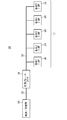
図1では、簡略化したシステム100の例図が提示されている。この簡略化したシステム100では、一連の負荷102、104、106、108、110(まとめて負荷112)はそれぞれ、スイッチが入ると最大5Ampの電流を引き出す。各負荷112は、共通の電線、又はバス120を介して回路ブレーカー130に接続されている。回路ブレーカー130は電源線、あるいは給電線122として知られる電源140に接続されている。簡略化したシステム100においては、需要率は80%と推定される。80%の需要率は、簡略化したシステム100が、任意の一時点において負荷112全てを足したものに対する最大電流の供給が80%を超えないことが予想されるように設計されていることを表す。負荷112全部に対する最大可能電流の供給は、負荷112の全てが同時に電流を使用したと仮定すると、25Amp(102、104、106、108、110それぞれがスイッチが入った時に使用する5Ampの5つの負荷合計)である。回路ブレーカー130はしたがって、バス120に20Ampを超える負荷がかかった場合(25Amp×80%需要率=20Amp)に落ちてしまう。バス120及び保護機構はしたがって、最大20Ampをサポートしさえすればよいが、バス120は負荷112のために、バス120の長さに沿って電圧低下を減らすために大きいものとすることができる。バス120の電線はおおむね20Ampに対応するようにサイズが調整されている。
In FIG. 1, an example diagram of a
しかしながら簡略化したシステム100には欠点がある。同時に電力を引き出す負荷112の数が多すぎる場合、回路ブレーカー130が落ちてしまう。負荷112のうちの一つが誤動作を起こすが20Ampよりも少ない電流を引き出す場合、故障状態であるにも関わらず回路ブレーカー130が落ちることはない。また、一より多い数の負荷112がバス120から電力を使用している場合、異なる負荷112の電圧はバス120全体の電圧低下に基づき違ったものとなる。例えば、負荷102、104、及び106がバス120から電流を使用している場合、負荷108及び110の電圧は、電源140によって供給される電圧よりもある程度低いものと成り得る。
However, the
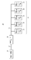
ここで、これらの及び他の問題を解決するための負荷調整システム200を提示している図2を参照する。図1の簡略化したシステム100と同様に、負荷調整システム200は、給電線122を介して回路ブレーカー130に電力を供給する電源140を有する。負荷調整システム200は、回路ブレーカー130をインテリジェント負荷202、204、206、208、210(まとめてインテリジェント負荷212)につなげる低電力バス220を有利に使用する。インテリジェント負荷212は、低電力バス220から電力を使用している時に、他のインテリジェント負荷212とともに調整を行う。
Reference is now made to FIG. 2, which presents a
ここで、図2及び3を参照すると、一実施形態において、インテリジェント負荷212は負荷112、及び検出/制御装置300を含む。一実施形態において、検出/制御装置300は負荷112、エネルギー貯蔵手段302、及び低電力バス220を相互接続させるスイッチ318を有する。一実施形態では、検出/制御装置300はエネルギー貯蔵手段302を有する。一実施形態では、エネルギー貯蔵手段302を一以上のインテリジェント負荷212が共有する。複数の実施形態では、エネルギー貯蔵手段302は、例えば再充電可能なニッケル−カドミウム(NiCad),リチウム−イオン(Li−Ion)、又はリチウムポリマー電池等の電池である。 複数の実施形態では、エネルギー貯蔵手段302は容量性素子である。複数の実施形態では、エネルギー貯蔵手段302は、一以上の完全起動のためにインテリジェント負荷212に電力供給するのに十分なエネルギーを貯蔵する。一以上の使用に対し電力を供給することによって、エネルギー貯蔵手段302は、インテリジェント負荷212がエネルギー貯蔵手段を再充電するために、低電力バス220からの電力の使用をスケジューリングし、長期間待機することを可能にする。
2 and 3, in one embodiment,
複数の実施形態では、エネルギー貯蔵手段302はインテリジェント負荷212において使用される検出機器304を稼働させるための電力を供給する。これらの実施形態では、エネルギー貯蔵手段302は、低電力バス220の現在の状態の検出を可能にするためにインテリジェント負荷212に初期の電力供給源を提供する。これにより、最初に低電力バス220に電力が送られた時に、インテリジェント負荷212のスタートを遅らせることができる。このことにより、最初にバス120に電力が供給された時に起こる厄介なブレーカーの遮断の一般的な原因が防止される。この状況は、一定期間スイッチが切られていた後でバス120を起動した直後に、複数の負荷112が電力の使用を開始した時に発生する。低電力バス220が最初に起動した時、直後にインテリジェント負荷212が電力を一斉に使用しないようにすることによって、厄介なブレーカーの遮断をなくすことができる。
In embodiments, the energy storage means 302 provides power to operate the
一実施形態では、検出/制御装置300は検出機器304を含み、検出機器304は低電力バス220の現在の状態を検出することを可能にする。一実施形態では、検出機器304を一又は複数のインテリジェント負荷212で共有する。複数の実施形態では、検出機器304は低電力バスの電圧、電流、又は電力に関連する事項を検出する手段を含む。検出手段の非限定的な例には、当技術分野で周知の、電圧センサ、電流量センサ、例えば低電力バス220に近接して又はその周囲に配置される誘導コイル306等の磁場センサ、ホール効果装置等の電場センサ308、固体センサ、又は他の任意の電気、磁気、又は電磁気センサが挙げられる。複数の実施形態では、検出機器304は例えば、低電力バス220の電圧、又は低電力バス220の一部を通って流れる電流を監視することによって、低電力バス220の電気状態を直接検出する。複数の実施形態では、検出機器304は、低電力バス220に近接する電場又は磁場の変化に起因する容量又は磁気の変化を監視するセンサ306、308を使用して、低電力バス220を受動的に監視する。一実施形態では、検出機器304は低電力バス220の現在の状態を表す信号を発信する関連回路を含む。非限定的な実施例では、検出機器304はアナログ・デジタルコンバーター(A/Dコンバーター310)、検出/制御装置300の要素間の相互作用、及び/又は外部の装置から検出信号を受信する通信ポート316を制御するプロセッサ又はCPU312を含む。非限定的な実施形態では、CPU312は、例えば非限定的に、DSP、ARMプロセッサ、プログラマブル論理装置、ASIC、又は当業者に既知のほかの全てのプロセッサを含む、任意の種類のプロセッサである。複数の実施形態では、CPU312は検出/制御装置のほかのコンポーネントからの入力に基づき決定を行う機器である。CPU312はしたがって、スイッチ318がいつ負荷112、エネルギー貯蔵手段302、及び低電力バス220を相互接続させるかを決定するコントローラである。入力として、CPUはプログラミング、センサ306、308からの入力、例えば他のインテリジェント負荷212等のほかの装置からの入力、検出/制御装置300の他のコンポーネントからの入力、又は通信ポート316からの通信信号として受信する入力を使用することができる。
In one embodiment, the detection /
一実施形態では、検出/制御装置300及び/又は検出機器304は、インテリジェント負荷212に完全に統合されている。一実施形態では、検出機器304、又は検出/制御装置300は、ASIC、ハイブリッドチップ、又は他のカスタマイズ可能なチップ、回路又はチップの組合せ及び/又は検出又は検出/制御機能を行う回路である。一実施形態では、検出機器304は他の全てのインテリジェント負荷212とは分離されている。インテリジェント負荷212が検出機器304を別のインテリジェント負荷212と共有しているこの実施形態、及び複数の実施形態では、検出機器304は、検出機器304をセンサ306、308と接続する検出入力314、又は別のインテリジェント負荷212の検出出力(図示せず)を含む。一実施形態では、インテリジェント負荷212はさらに、他のインテリジェント負荷212と信号をやり取りする通信ポート又は通信手段316を含む。非限定的な実施形態では、通信手段316は一以上のデータ回線、シリアルデータ通信ポート、無線データ通信パッケージ、及び低電力バス220上で通信するための送電線通信装置を含む。
In one embodiment, the detection /
複数の実施形態では、低電力バス220から電力を引き出す前に、負荷調整システム200の各インテリジェント負荷212は検出機器304を使用して低電力バス220の現在の状態を検出する。複数の実施形態では、インテリジェント負荷212は他のインテリジェント負荷212と連携して、低電力バス220からの電力の使用のスケジューリングを行う。複数の実施形態では、インテリジェント負荷212は回路ブレーカー130又は電力使用のインテリジェントキューイング又はスケジューリングを行うコンピュータシステム(図示せず)とともに電力の使用のスケジューリングを行う。複数の実施形態では、負荷112及びインテリジェント負荷212の両方が同じバス120、220に設置されている。複数の実施形態では、このインテリジェント負荷212は電力を使用しようとする前に、低電力バス220から電力が使用されなくなるまで待機する。複数の実施形態では、インテリジェント負荷212は電力を使用する前に、低電力バス220に利用可能な容量が残っているかどうかを判断するため、2つ以上のインテリジェント負荷212が、回路ブレーカー130を落とすことなく、同時に電力を使用することができる。
In embodiments, each
一実施形態では、ユーザが多数のインテリジェント負荷212を同時に起動させようとした場合に、インテリジェント負荷212は、起動して電流を使用するべきかどうかを検出する。一実施形態では、インテリジェント負荷212は、例えばディップスイッチ、又は他の任意の優先度を確立する手段を用いて優先化される。優先度が最も高いインテリジェント負荷212が最初に起動する。別の実施形態では、最初に起動したインテリジェント負荷212が最初に電力を使用する。いずれの実施形態においても、他のインテリジェント負荷212は選択された時間間隔の間、スタンバイモードに入る。この時間間隔は、例えば再試行する前の1秒等の固定であってよい、又は試行間の時間間隔を500ミリ秒ずつ増加させる等のバックオフ法を使用することができる。低電力220を再試行する前の時間の長さは、適応的であってよい、又は確率変数、例えば500ミリ秒+/−200ミリ秒を有することができる。これらの実施形態では、図1の簡略化したシステム100において起こり得る回路ブレーカーの遮断の代わりに、幾つかのインテリジェント負荷212は起動する前に遅延する。起動間の待ち時間が短い場合は、各インテリジェント負荷212の起動と電流の使用が速ければ速いほど、共通の低電力バス220に据付することができるインテリジェント負荷212の数が増える。インテリジェント負荷212が通信を行う一実施形態では、インテリジェント負荷212は別のインテリジェント負荷212に動作を停止するように合図することができ、これによりオーバーライド機能が可能になる。例えば、最初に負荷調整システム200がオンになると、エネルギー貯蔵手段302を有する幾つかのインテリジェント負荷212が起動を開始して、エネルギー貯蔵手段302の充電を始めることができる。ユーザが手動で別のインテリジェント負荷212を起動させようとした場合、そのインテリジェント負荷212は別のインテリジェント負荷212に動作を停止するよう信号を送る。
In one embodiment, when a user attempts to activate multiple
複数の実施形態では、インテリジェント負荷212は他のインテリジェント負荷212、回路ブレーカー130、電源140、又はコンピュータシステム(図示せず)と連通して、電力の使用を調整する。例えば、インテリジェント負荷212は航空機のエンジンの発電機等の電源140と連通して、予想される電力の使用量を知らせることができ、これにより電力が必要でないときに発電機にアイドリングさせることができる。インテリジェント負荷212は回路ブレーカー130と連通することにより、回路ブレーカー130に予想される電力の使用量を警告することができる。装置又はインテリジェント負荷212からの電力の使用は特徴づけられており、これによりインテリジェント回路が、通常の電力使用操作の予期される範囲外の電力使用操作を遮断することが可能になる。電力の使用がそのインテリジェント負荷212の電力使用量の予期される許容範囲外である場合、回路ブレーカー130は知的に遮断する。一実施形態では、回路ブレーカー130は、予想される使用電力量のプロファイルを、インテリジェント負荷212による実際の使用電力量と比較する。例えば、ドアのロックの起動は、ドアロックの起動において使用されるインテリジェント負荷212による適切な電力の使用を識別するためのテンプレートとして使用することができる特有のサインプロファイルを有することができる。例えば、図4a及び4bを参照すると、28Vソレノイドの電流グラフ400及び電圧グラフ410が示されている。電流グラフ400及び電圧グラフ410は、ソレノイドの電流の使用402及び電圧の低下404には同一の特徴、通電直後に起き、サインプロファイルを作成するのに使用可能なスパイクを有することを示している。
In embodiments, the
図4a及び4bの電流グラフ400及び電圧グラフ410を続けて参照すると、負荷112として6つの0.4Ampソレノイドに電力供給する28V回路の電流の使用402及び電圧の低下404が示されている。図4a及び4bの電流グラフ400及び電圧グラフ410の構成は、インテリジェント負荷212が用いられていない簡略化したシステム100と同様のものである。初期の電流の使用402は、0Ampであり、電圧の低下404は0Vである。バス120は公称28V回路である。0.5秒において一のソレノイド負荷112が起動し、0.4Ampの電流が使用される。またこれにより、28V回路の電圧が約0.75V低下する。1秒と3秒の間に、他のソレノイド負荷112が起動し、また動作を停止する。1.5秒において、複数のソレノイドが起動し、最大1.8Ampの電流が使用され、これにより28V回路の電圧が3.5V低下する。図4a及び4bに示す実施例では、回路ブレーカー130、電源140、及び配線122、120は、過熱を防止する又は回路ブレーカー130の遮断を回避するために1.8Ampの電流に対応できなくてはならない。さらに、ソレノイド負荷112又は他の負荷112は、利用度が高い間は、28V回路に供給される低い24.5電圧を利用して稼動できなくてはならない。
With continued reference to the
ここで、図5a及び5bのインテリジェント負荷500の電流グラフと、インテリジェント負荷510の電圧グラフを参照すると、インテリジェント負荷212として構成された6つの0.4Ampソレノイドに電力供給している28V回路の電流の使用502が低下し、電圧の低下504が低減していることが示されている。初期の低下した電流の使用502は0Ampであり、低減された電圧の低下504は0Vである。低電力バス220は公称28V回路である。1.0秒において、インテリジェント負荷212として構成された一つのソレノイドが起動し、0.4Ampの電流を使用する。またこれにより、28V回路の電圧が約0.75V低下する。しかしながら、最初のソレノイドの動作が停止するまで、インテリジェント負荷212として構成された他のソレノイドは起動しない。すべてのソレノイドが起動するまでが図4a及び4bにおいてよりもいくらか長くかかるが、インテリジェント負荷212によって短縮された時間が低デューティサイクル負荷の追加時間を相殺する。一つの利点は、低下した電流の使用502が0.4Ampを超えて上がることはなく、低減された電圧の低下504が0.75ボルトを超えることがないため、28V回路が約27.25ボルトを下回ることがないことである。これにより、0.4Ampのみに対応すればよい回路ブレーカー130、電源140、及び配線122、120の使用、及び27.25ボルト以上の電圧で稼動するソレノイドを使用することが有利に可能になる。
Now referring to the current graph of
開示のシステム及び方法は、例えば電子ロック、貨物ドア用モータ、及び単一使用のメンテナンスディスプレイ等の断続的に使用されるインテリジェント負荷500に電力供給するのに使用した時に、大幅な改善が得られる。これらの及び他の低使用の負荷は、これらをサポートするのに必要な、最低量の電力インフラストラクチャで据付けることができるため、電気システムの設計者は電力の低いコンポーネント、発電機及び配線を使用することが可能になる。低電力発電機及び配線はおおむね小さく、費用も安く、重量も軽いため、空間の使用を抑え、製造費用を削減し、また航空機の重量が低減されるため顧客の繰り返しの燃料費が削減される。したがって、開示のシステム及び方法は、従来の方法を使用して設計されたシステムよりも小さくて軽い、経済的な電力システム及び電力インフラストラクチャの設計及び実行を有利に可能にする。
The disclosed system and method provide significant improvements when used to power intermittently used
ここで、インテリジェント負荷212の操作600方法の例示のフロー図を提示する図6を参照する。最初のステップにおいて、低電力バス220の電源がオンになる602。インテリジェント負荷212は、例えばユーザが貨物ドアを開ける等の、ユーザによるインテリジェント負荷212の起動等の起動604を待機する状態に入る。例えば信号又はボタンを押すことによって、いったんインテリジェント負荷212が起動する606と、インテリジェント負荷212は、低電力220から活発に電力を使用するかもしれない他のインテリジェント負荷212について低電力バス220を監視する。別の負荷が活発に電流を使用している場合、インテリジェント負荷212は起動を遅延し610、再び低電力バス220を監視する608。他の負荷212が電流を使用していない場合、インテリジェント負荷212は起動又は稼動し612、その後インテリジェント負荷212は起動604を待機する動作に戻る。
Reference is now made to FIG. 6, which presents an exemplary flow diagram of an
さらなる実施形態は、下記の段落に示すように主張することができる。 Further embodiments can be claimed as shown in the following paragraphs.
A18.装置であって:電力バスから断続的に電力を使用するためのスイッチ;前記スイッチと電気的に連通している負荷;前記電力バスの電気状態を検出するためのセンサ;及び前記スイッチ及び前記検出手段と連通しているコントローラを含み、前記コントローラが、前記電力バスの前記電気状態に少なくとも部分的に基づいて前記負荷に電力を供給するために、前記スイッチを制御して前記電力バスから断続的に電力を使用する装置。 A18. An apparatus comprising: a switch for intermittently using power from a power bus; a load in electrical communication with the switch; a sensor for detecting an electrical state of the power bus; and the switch and the detection A controller in communication with the means, wherein the controller controls the switch to intermittently remove power from the power bus to provide power to the load based at least in part on the electrical state of the power bus. A device that uses electricity.
A19.前記スイッチを介して前記電力バスと電気的に連通している電池をさらに含み、前記電池が前記スイッチを介した断続的な電力の使用を利用して貯蔵された電力で充電され、前記負荷が前記電池と電気的に連通しており、前記電池は、前記スイッチが前記電力バスから電力を使用していない時に、前記貯蔵された電力を前記負荷に供給する、請求項A18の装置。 A19. The battery further includes a battery in electrical communication with the power bus via the switch, the battery is charged with stored power using intermittent power usage via the switch, and the load is The apparatus of claim A18, in electrical communication with the battery, wherein the battery supplies the stored power to the load when the switch is not using power from the power bus.
A20.前記コントローラが、第2負荷の前記電力バスからの電力の使用に起因する前記電力バスの電圧低下、前記第2負荷の前記電力バスからの電力を使用に起因する前記電力バスの電流の増加、及び前記電力バスが使用されていることを示す信号の受信からなるグループから選択された状態に基づいて、前記スイッチが前記電力バスから電力を使用することを阻止する、請求項A18の装置。 A20. A voltage drop of the power bus resulting from the use of power from the power bus of a second load; an increase in current of the power bus resulting from using power from the power bus of the second load; The apparatus of claim A18, wherein the switch prevents use of power from the power bus based on a state selected from a group consisting of receiving a signal indicating that the power bus is in use.
図面及び上記に示す本発明の実施形態は、添付の請求項の範囲内で実行可能である多数の実施形態の例示である。負荷調整システム100の他の多数の構成を、開示の方法の利点を生かして作製することが可能であると考えられる。本願により発行される特許の範囲は、添付の請求項の範囲によってのみ限定されることが本出願人の意図するところである。
The drawings and the embodiments of the invention set forth above are illustrative of numerous embodiments that can be practiced within the scope of the appended claims. It is contemplated that many other configurations of the
100 簡略化したシステム
120 バス
122 電線
112 負荷
200 負荷調整システム
212 インテリジェント負荷
220 低電力バス
300 検出/制御装置
304 検出機器
306 誘導コイル
400 電流グラフ
402 電流の使用
404 電圧の低下
410 電圧グラフ
500 電流グラフ
502 電流の使用
504 電圧の低下
510 電圧グラフ
600 インテリジェント負荷の操作方法
DESCRIPTION OF
Claims (17)
前記電力バスからの電力を断続的に使用する第1電動装置;
前記電力バスからの電力を断続的に使用する第2電動装置;及び
前記第2電動装置が前記電力バスからの電力を使用していることを検出する手段
を含み、
前記第2電動装置が前記電力バスからの電力を使用している時は、前記第1電動装置が前記電力バスからの電力を使用することが阻止される、
システム。 Power bus;
A first electric device that intermittently uses power from the power bus;
A second electric device that intermittently uses power from the power bus; and means for detecting that the second electric device is using power from the power bus;
When the second electric device uses power from the power bus, the first electric device is prevented from using power from the power bus.
system.
前記電気回路を通電させ;
前記複数のインテリジェント負荷によって、前記電気回路から複数の断続的な電力の使用を調整して、回路ブレーカーが前記電気回路を電源から接続解除することを阻止する
操作を含む方法。 Connecting multiple intelligent loads to the electrical circuit;
Energizing the electrical circuit;
Adjusting the use of a plurality of intermittent powers from the electrical circuit by the plurality of intelligent loads to prevent a circuit breaker from disconnecting the electrical circuit from a power source.
操作をさらに含む、請求項9に記載の方法。 The method of claim 9, further comprising an operation of preventing the first intelligent load from using intermittent power while the second intelligent load is using power intermittently.
前記第2インテリジェント負荷の前記断続的な電力の使用を検出している操作中は、前記第1インテリジェント負荷の断続的な電力の使用を阻止する
操作をさらに含む、請求項10に記載の方法。 Detecting the intermittent power usage of the second intelligent load;
The method of claim 10, further comprising preventing an intermittent power usage of the first intelligent load during an operation detecting the intermittent power usage of the second intelligent load.
操作をさらに含む、請求項9に記載の方法。 The method of claim 9, further comprising prioritizing a plurality of intermittent power usages of the plurality of intelligent loads from the electrical circuit.
断続的な電力の使用を利用して、前記エネルギー貯蔵手段を充電する
操作をさらに含む、請求項9に記載の方法。 From the energy stored in the energy storage means to power the start of the first intelligent load;
The method of claim 9, further comprising charging the energy storage means using intermittent power usage.
Applications Claiming Priority (2)
| Application Number | Priority Date | Filing Date | Title |
|---|---|---|---|
| US12/896,691 US20120080940A1 (en) | 2010-10-01 | 2010-10-01 | Load Coordinating Power Draw for Limited Ampacity Circuits |
| US12/896,691 | 2010-10-01 |
Publications (2)
| Publication Number | Publication Date |
|---|---|
| JP2012080762A true JP2012080762A (en) | 2012-04-19 |
| JP2012080762A5 JP2012080762A5 (en) | 2014-10-16 |
Family
ID=44719338
Family Applications (1)
| Application Number | Title | Priority Date | Filing Date |
|---|---|---|---|
| JP2011209877A Withdrawn JP2012080762A (en) | 2010-10-01 | 2011-09-26 | Use of electric power with load adjusted in circuit having limited current capacity |
Country Status (5)
| Country | Link |
|---|---|
| US (1) | US20120080940A1 (en) |
| EP (1) | EP2437367A2 (en) |
| JP (1) | JP2012080762A (en) |
| CN (1) | CN102447257A (en) |
| CA (1) | CA2747916A1 (en) |
Families Citing this family (15)
| Publication number | Priority date | Publication date | Assignee | Title |
|---|---|---|---|---|
| US7846579B2 (en) | 2005-03-25 | 2010-12-07 | Victor Krasnov | Thin film battery with protective packaging |
| US8679674B2 (en) * | 2005-03-25 | 2014-03-25 | Front Edge Technology, Inc. | Battery with protective packaging |
| US8865340B2 (en) | 2011-10-20 | 2014-10-21 | Front Edge Technology Inc. | Thin film battery packaging formed by localized heating |
| US9887429B2 (en) | 2011-12-21 | 2018-02-06 | Front Edge Technology Inc. | Laminated lithium battery |
| US8864954B2 (en) | 2011-12-23 | 2014-10-21 | Front Edge Technology Inc. | Sputtering lithium-containing material with multiple targets |
| US9077000B2 (en) | 2012-03-29 | 2015-07-07 | Front Edge Technology, Inc. | Thin film battery and localized heat treatment |
| US9257695B2 (en) | 2012-03-29 | 2016-02-09 | Front Edge Technology, Inc. | Localized heat treatment of battery component films |
| US9159964B2 (en) | 2012-09-25 | 2015-10-13 | Front Edge Technology, Inc. | Solid state battery having mismatched battery cells |
| US8753724B2 (en) | 2012-09-26 | 2014-06-17 | Front Edge Technology Inc. | Plasma deposition on a partially formed battery through a mesh screen |
| US9356320B2 (en) | 2012-10-15 | 2016-05-31 | Front Edge Technology Inc. | Lithium battery having low leakage anode |
| US9715271B2 (en) * | 2014-05-06 | 2017-07-25 | Microchip Technology Incorporated | USB power port control |
| US10008739B2 (en) | 2015-02-23 | 2018-06-26 | Front Edge Technology, Inc. | Solid-state lithium battery with electrolyte |
| US10608432B2 (en) * | 2018-03-30 | 2020-03-31 | Midea Group Co., Ltd. | Appliance power management system |
| US11223201B1 (en) | 2020-07-10 | 2022-01-11 | Richard Bailey | Electrical power sharing system and method |
| JP7189191B2 (en) | 2020-10-26 | 2022-12-13 | 矢崎総業株式会社 | power control unit |
Family Cites Families (35)
| Publication number | Priority date | Publication date | Assignee | Title |
|---|---|---|---|---|
| FR2088954A5 (en) * | 1970-04-30 | 1972-01-07 | Radiotechnique Compelec | |
| US3925680A (en) * | 1975-04-04 | 1975-12-09 | William A Dixon | Method and system for regulating peak residential power demand |
| US4560909A (en) * | 1982-09-28 | 1985-12-24 | General Electric Company | Dual load remote power control for a ceiling fan |
| US4520274A (en) * | 1983-07-22 | 1985-05-28 | Stants Richard O | Method and apparatus for controlling the loads or a plurality of units on a shared source |
| US4777379A (en) * | 1984-11-02 | 1988-10-11 | Young Danny J | Power cycling apparatus |
| US4847722A (en) * | 1987-09-17 | 1989-07-11 | Bennett Robert P | Refrigerator and microwave oven and overdemand interrupt circuit |
| US4880954A (en) * | 1988-06-03 | 1989-11-14 | Bennett Robert P | Combined refrigerator and microwave oven with timed overload protection |
| JP2915037B2 (en) * | 1990-01-08 | 1999-07-05 | 株式会社日立製作所 | Operation control system of electric load for automobile |
| US5504400A (en) * | 1994-09-23 | 1996-04-02 | Dalnodar; David C. | Two-channel AC light dimmer and lighting system |
| US5521359A (en) * | 1995-04-18 | 1996-05-28 | Bone; Charles A. | System for coordinating operation of microwave oven with a second appliance |
| US5883445A (en) * | 1996-10-22 | 1999-03-16 | Holman; Frank T. | Power sharing device |
| US5844326A (en) * | 1997-06-23 | 1998-12-01 | Cruising Equipment Company, Inc. | Managed electrical outlet for providing rank-ordered over-current protection |
| US6157008A (en) * | 1999-07-08 | 2000-12-05 | Maytag Corporation | Power distribution system for an appliance |
| US6826029B2 (en) * | 2001-08-30 | 2004-11-30 | The Boeing Company | Methods and apparatus for distributing electrical power |
| US20050280970A1 (en) * | 2004-06-16 | 2005-12-22 | Cyber Switching, Inc. | Current protection apparatus and method |
| DE10233876B4 (en) * | 2002-07-25 | 2005-03-03 | Austriamicrosystems Ag | Circuit arrangement for controlling two independent loads operable with a rectified AC voltage |
| US20040075343A1 (en) * | 2002-09-05 | 2004-04-22 | Paul Wareham | System and method for power load management |
| US6940272B2 (en) * | 2002-10-10 | 2005-09-06 | Green Socket Ltd. | Electric socket control device |
| US7373222B1 (en) * | 2003-09-29 | 2008-05-13 | Rockwell Automation Technologies, Inc. | Decentralized energy demand management |
| EP1678587A4 (en) * | 2003-10-24 | 2009-10-28 | Square D Co | Intelligent power management control system |
| US7514815B2 (en) * | 2004-09-28 | 2009-04-07 | American Power Conversion Corporation | System and method for allocating power to loads |
| AU2005291729C1 (en) * | 2004-10-05 | 2010-07-08 | 2D2C, Inc. | Electrical power distribution system |
| US7547990B2 (en) * | 2005-07-12 | 2009-06-16 | Diran Varzhabedian | Backup power system for electrical appliances |
| WO2007082351A1 (en) * | 2006-01-23 | 2007-07-26 | Datatainer Pty Ltd | Data processing apparatus |
| US7486056B2 (en) * | 2006-11-15 | 2009-02-03 | Elster Electricity, Llc | Input current or voltage limited power supply |
| TWI430534B (en) * | 2007-05-08 | 2014-03-11 | American Power Conv Corp | Alternative-source energy management |
| US7781908B2 (en) * | 2007-07-19 | 2010-08-24 | Igo, Inc. | Output power port management control |
| US20090164820A1 (en) * | 2007-12-24 | 2009-06-25 | Hewlett-Packard Development Company, L.P. | Methods and apparatus for managing power on a computer in the event of a power interruption |
| US7658625B2 (en) * | 2008-03-07 | 2010-02-09 | Microsoft Corporation | AC Power adapter with swiveling plug having folding prongs |
| TWI364518B (en) * | 2008-07-29 | 2012-05-21 | Ind Tech Res Inst | Power saving managing method and system using the same |
| US8504215B1 (en) * | 2008-11-04 | 2013-08-06 | Symantec Corporation | Systems and methods for using alternate power sources to manage the power draw on a power grid |
| CN104935019B (en) * | 2009-01-06 | 2017-12-12 | 捷通国际有限公司 | Wireless charging system with rating of set accordance |
| US8497658B2 (en) * | 2009-01-22 | 2013-07-30 | Qualcomm Incorporated | Adaptive power control for wireless charging of devices |
| US8315745B2 (en) * | 2009-04-24 | 2012-11-20 | Hunter Defense Technologies, Inc. | Mobile micro-grid power system controller and method |
| US8626319B2 (en) * | 2010-09-29 | 2014-01-07 | Rockwell Automation Technologies, Inc. | Modular energy load management |
-
2010
- 2010-10-01 US US12/896,691 patent/US20120080940A1/en not_active Abandoned
-
2011
- 2011-08-03 CA CA 2747916 patent/CA2747916A1/en not_active Abandoned
- 2011-09-06 EP EP20110180161 patent/EP2437367A2/en not_active Withdrawn
- 2011-09-23 CN CN2011102916127A patent/CN102447257A/en active Pending
- 2011-09-26 JP JP2011209877A patent/JP2012080762A/en not_active Withdrawn
Also Published As
| Publication number | Publication date |
|---|---|
| US20120080940A1 (en) | 2012-04-05 |
| CA2747916A1 (en) | 2012-04-01 |
| EP2437367A2 (en) | 2012-04-04 |
| CN102447257A (en) | 2012-05-09 |
Similar Documents
| Publication | Publication Date | Title |
|---|---|---|
| JP2012080762A (en) | Use of electric power with load adjusted in circuit having limited current capacity | |
| EP3190682B1 (en) | Power supply system and method | |
| EP2670015B1 (en) | Power control device and power control method | |
| EP3029804B1 (en) | Charging facility and energy management method for charging facility | |
| JP4364502B2 (en) | Method and apparatus for supplying resting current to a vehicle with a multi-voltage on-board electrical system | |
| US20050141154A1 (en) | Power averaging and power load management system | |
| CN205335963U (en) | A battery stand -by unit and system for $facing load supply non -firm power | |
| EP2299556B1 (en) | Battery charging and electrical energy delivery system and battery operated system | |
| CN104052353B (en) | Generating set self adaptation droop control method | |
| US8614524B2 (en) | Onboard power supply and method for operating an onboard power supply | |
| KR101383194B1 (en) | On-board electrical system for a vehicle and also control apparatus for an on-board electrical system | |
| KR20150023040A (en) | Charging/discharging device | |
| JP2011078249A (en) | Battery management device, secondary battery device, and vehicle | |
| WO2010090666A1 (en) | System and method for limiting losses in an uninterruptible power supply | |
| JP2013225971A (en) | Charge controller and vehicle charging system | |
| JP2015173592A (en) | Distribution board device | |
| EP2648322A1 (en) | Power interruption bridge circuit | |
| CN110323734A (en) | Priority load for the electric system with multiple power supplys is shared | |
| AU2008241371B2 (en) | Battery management system | |
| WO2012060766A1 (en) | Activation device and activation method for a dual-battery system | |
| JP2009071922A (en) | Dc backup power supply device and method of controlling the same | |
| CN107171377B (en) | Method for storing battery units configured for installation in an electric vehicle in an intermediate storage facility | |
| JP2011162147A (en) | Vehicular power source supply device and vehicular control device | |
| EP1294073B1 (en) | Backup power module for industrial control and monitoring network | |
| CN104969439A (en) | Method for operating an energy supply unit for an on-board power system of a motor vehicle |
Legal Events
| Date | Code | Title | Description |
|---|---|---|---|
| A521 | Request for written amendment filed |
Free format text: JAPANESE INTERMEDIATE CODE: A523 Effective date: 20140902 |
|
| A621 | Written request for application examination |
Free format text: JAPANESE INTERMEDIATE CODE: A621 Effective date: 20140902 |
|
| A761 | Written withdrawal of application |
Free format text: JAPANESE INTERMEDIATE CODE: A761 Effective date: 20141127 |