JP2012080664A - User energy management system - Google Patents
User energy management system Download PDFInfo
- Publication number
- JP2012080664A JP2012080664A JP2010223203A JP2010223203A JP2012080664A JP 2012080664 A JP2012080664 A JP 2012080664A JP 2010223203 A JP2010223203 A JP 2010223203A JP 2010223203 A JP2010223203 A JP 2010223203A JP 2012080664 A JP2012080664 A JP 2012080664A
- Authority
- JP
- Japan
- Prior art keywords
- natural energy
- home
- home gateway
- management system
- information
- Prior art date
- Legal status (The legal status is an assumption and is not a legal conclusion. Google has not performed a legal analysis and makes no representation as to the accuracy of the status listed.)
- Pending
Links
Images


Classifications
-
- H—ELECTRICITY
- H02—GENERATION; CONVERSION OR DISTRIBUTION OF ELECTRIC POWER
- H02J—CIRCUIT ARRANGEMENTS OR SYSTEMS FOR SUPPLYING OR DISTRIBUTING ELECTRIC POWER; SYSTEMS FOR STORING ELECTRIC ENERGY
- H02J3/00—Circuit arrangements for ac mains or ac distribution networks
- H02J3/12—Circuit arrangements for ac mains or ac distribution networks for adjusting voltage in ac networks by changing a characteristic of the network load
- H02J3/14—Circuit arrangements for ac mains or ac distribution networks for adjusting voltage in ac networks by changing a characteristic of the network load by switching loads on to, or off from, network, e.g. progressively balanced loading
-
- H—ELECTRICITY
- H02—GENERATION; CONVERSION OR DISTRIBUTION OF ELECTRIC POWER
- H02J—CIRCUIT ARRANGEMENTS OR SYSTEMS FOR SUPPLYING OR DISTRIBUTING ELECTRIC POWER; SYSTEMS FOR STORING ELECTRIC ENERGY
- H02J13/00—Circuit arrangements for providing remote indication of network conditions, e.g. an instantaneous record of the open or closed condition of each circuitbreaker in the network; Circuit arrangements for providing remote control of switching means in a power distribution network, e.g. switching in and out of current consumers by using a pulse code signal carried by the network
-
- G—PHYSICS
- G06—COMPUTING; CALCULATING OR COUNTING
- G06Q—INFORMATION AND COMMUNICATION TECHNOLOGY [ICT] SPECIALLY ADAPTED FOR ADMINISTRATIVE, COMMERCIAL, FINANCIAL, MANAGERIAL OR SUPERVISORY PURPOSES; SYSTEMS OR METHODS SPECIALLY ADAPTED FOR ADMINISTRATIVE, COMMERCIAL, FINANCIAL, MANAGERIAL OR SUPERVISORY PURPOSES, NOT OTHERWISE PROVIDED FOR
- G06Q50/00—Systems or methods specially adapted for specific business sectors, e.g. utilities or tourism
- G06Q50/06—Electricity, gas or water supply
-
- H—ELECTRICITY
- H02—GENERATION; CONVERSION OR DISTRIBUTION OF ELECTRIC POWER
- H02J—CIRCUIT ARRANGEMENTS OR SYSTEMS FOR SUPPLYING OR DISTRIBUTING ELECTRIC POWER; SYSTEMS FOR STORING ELECTRIC ENERGY
- H02J3/00—Circuit arrangements for ac mains or ac distribution networks
-
- H—ELECTRICITY
- H02—GENERATION; CONVERSION OR DISTRIBUTION OF ELECTRIC POWER
- H02J—CIRCUIT ARRANGEMENTS OR SYSTEMS FOR SUPPLYING OR DISTRIBUTING ELECTRIC POWER; SYSTEMS FOR STORING ELECTRIC ENERGY
- H02J2310/00—The network for supplying or distributing electric power characterised by its spatial reach or by the load
- H02J2310/10—The network having a local or delimited stationary reach
- H02J2310/12—The local stationary network supplying a household or a building
- H02J2310/14—The load or loads being home appliances
-
- Y—GENERAL TAGGING OF NEW TECHNOLOGICAL DEVELOPMENTS; GENERAL TAGGING OF CROSS-SECTIONAL TECHNOLOGIES SPANNING OVER SEVERAL SECTIONS OF THE IPC; TECHNICAL SUBJECTS COVERED BY FORMER USPC CROSS-REFERENCE ART COLLECTIONS [XRACs] AND DIGESTS
- Y02—TECHNOLOGIES OR APPLICATIONS FOR MITIGATION OR ADAPTATION AGAINST CLIMATE CHANGE
- Y02B—CLIMATE CHANGE MITIGATION TECHNOLOGIES RELATED TO BUILDINGS, e.g. HOUSING, HOUSE APPLIANCES OR RELATED END-USER APPLICATIONS
- Y02B70/00—Technologies for an efficient end-user side electric power management and consumption
- Y02B70/30—Systems integrating technologies related to power network operation and communication or information technologies for improving the carbon footprint of the management of residential or tertiary loads, i.e. smart grids as climate change mitigation technology in the buildings sector, including also the last stages of power distribution and the control, monitoring or operating management systems at local level
- Y02B70/3225—Demand response systems, e.g. load shedding, peak shaving
-
- Y—GENERAL TAGGING OF NEW TECHNOLOGICAL DEVELOPMENTS; GENERAL TAGGING OF CROSS-SECTIONAL TECHNOLOGIES SPANNING OVER SEVERAL SECTIONS OF THE IPC; TECHNICAL SUBJECTS COVERED BY FORMER USPC CROSS-REFERENCE ART COLLECTIONS [XRACs] AND DIGESTS
- Y04—INFORMATION OR COMMUNICATION TECHNOLOGIES HAVING AN IMPACT ON OTHER TECHNOLOGY AREAS
- Y04S—SYSTEMS INTEGRATING TECHNOLOGIES RELATED TO POWER NETWORK OPERATION, COMMUNICATION OR INFORMATION TECHNOLOGIES FOR IMPROVING THE ELECTRICAL POWER GENERATION, TRANSMISSION, DISTRIBUTION, MANAGEMENT OR USAGE, i.e. SMART GRIDS
- Y04S20/00—Management or operation of end-user stationary applications or the last stages of power distribution; Controlling, monitoring or operating thereof
- Y04S20/20—End-user application control systems
- Y04S20/222—Demand response systems, e.g. load shedding, peak shaving
-
- Y—GENERAL TAGGING OF NEW TECHNOLOGICAL DEVELOPMENTS; GENERAL TAGGING OF CROSS-SECTIONAL TECHNOLOGIES SPANNING OVER SEVERAL SECTIONS OF THE IPC; TECHNICAL SUBJECTS COVERED BY FORMER USPC CROSS-REFERENCE ART COLLECTIONS [XRACs] AND DIGESTS
- Y04—INFORMATION OR COMMUNICATION TECHNOLOGIES HAVING AN IMPACT ON OTHER TECHNOLOGY AREAS
- Y04S—SYSTEMS INTEGRATING TECHNOLOGIES RELATED TO POWER NETWORK OPERATION, COMMUNICATION OR INFORMATION TECHNOLOGIES FOR IMPROVING THE ELECTRICAL POWER GENERATION, TRANSMISSION, DISTRIBUTION, MANAGEMENT OR USAGE, i.e. SMART GRIDS
- Y04S20/00—Management or operation of end-user stationary applications or the last stages of power distribution; Controlling, monitoring or operating thereof
- Y04S20/20—End-user application control systems
- Y04S20/242—Home appliances
Abstract
Description
本発明の実施形態は、需要家のエネルギーを管理する需要家エネルギー管理システムに
関する。
Embodiments described herein relate generally to a consumer energy management system that manages consumer energy.
家庭や店舗など、電力需要家内の複数の機器の消費エネルギーを表示し、また時として
、制御することにより、省エネ、省コスト、CO2排出量の削減などを行う需要家エネルギ
ー管理システムが知られている(非特許文献1参照)。従来の需要家エネルギー管理シス
テムは、需要家内の機器類および制御装置から構成される。機器類は、家庭では複数の家
電機器から構成されることが多い。非特許文献1に示された従来の家庭エネルギー管理シ
ステムについて以下説明する。従来の家庭エネルギー管理システムでは、多くのシステム
の実証試験が行われているが、主な制御として(1)エアコンの在不在制御:人が居ない
ときにはエアコンを切る、(2)照明の在不在制御・明るさ制御:人が居ないときには照
明を切る、または、暗くする、(3)待機電力遮断、などである。消費エネルギーの表示
としては、電力消費量やガス消費量の表示をはじめとして、複数世帯間の比較により省エ
ネコンテスト、外気温などに応じたアドバイス、CO2排出量の表示がある。
A consumer energy management system is known that displays energy consumption of multiple devices in power consumers, such as homes and stores, and sometimes controls them to save energy, save costs, and reduce CO2 emissions. (See Non-Patent Document 1). A conventional consumer energy management system is composed of equipment and a control device in a consumer. Devices are often composed of a plurality of home appliances at home. The conventional home energy management system shown in Non-Patent Document 1 will be described below. In the conventional home energy management system, many system verification tests have been carried out. The main control is (1) control of the presence / absence of the air conditioner: turn off the air conditioner when no one is present, (2) absence / presence of lighting Control / Brightness control: Turn off or darken lights when no one is present, (3) cut off standby power, etc. The display of energy consumption includes display of power consumption and gas consumption, energy saving contest by comparing between multiple households, advice according to outside temperature, and display of CO2 emissions.
過去の多くの実証試験の結果、直接的な自動制御による省エネルギー効果は小さい場合
が多く、逆にコストを大幅に増加させることから、好ましくないと言う評価が多い。一方
、エネルギー見える化は費用に対して効果があり、さらに使用者の興味を持ち積極的に省
エネに協力してもらうための工夫として、見易さの工夫、わかりやすさの工夫、新鮮な情
報の提供、楽しさが必要とされている。
As a result of many past demonstration tests, the energy saving effect by direct automatic control is often small, and conversely, the cost is greatly increased. Energy visualization, on the other hand, is cost effective, and in addition to providing users with interest and actively cooperating with energy conservation, it is easy to see, easy to understand, and provides fresh information. Fun is needed.
従来の需要家エネルギー管理システムは、家庭の電力やガスなどの消費エネルギーを減
らすことにより、家庭のエネルギーコストを削減することにより家庭に利益を分与しつつ
、最終的には社会のCO2発生量削減を目指したものである。しかし上述のように、家庭の
消費エネルギーを削減することを目標にしても、家庭の不満を抑えつつ自動制御で削減で
きる割合は多くない。その結果、消費エネルギーの見える化による住民自らの参加意識に
頼った省エネになるが、それでも、非特許文献1に記載されているように、省エネの目標
として電力消費量の10%程度の削減という小幅な目標にとどまっている。
Conventional consumer energy management systems share household benefits by reducing household energy costs by reducing household energy consumption, such as electricity and gas, and ultimately the amount of CO2 generated by society. It aims at reduction. However, as described above, even if the goal is to reduce household energy consumption, there are not many ratios that can be reduced by automatic control while suppressing household dissatisfaction. As a result, the energy saving depends on the residents' consciousness of participation through the visualization of the energy consumption. However, as described in Non-Patent Document 1, the energy saving target is about 10% reduction in power consumption. It remains a small goal.
本発明は上記の事情に鑑みてなされたものであり、豊富に存在するにもかかわらず天候
や太陽位置に大きく依存し、不安定であるために、電力系統への導入が遅れている自然エ
ネルギーを有効に利用し、需要家のCO2発生量を大幅に削減することを可能とすることに
ある。
The present invention has been made in view of the above circumstances, and although it is abundant, it relies heavily on the weather and the solar position, and is unstable, so it is a natural energy that has been delayed in introduction to the power system. It is to make it possible to effectively reduce the amount of CO2 generated by consumers.
上記の目的を達成するために、実施形態の需要家エネルギー管理システムは、少なくと
も電力系統に連系された自然エネルギー発電情報またはCO2原単位の情報を受け取るホ
ームゲートウェイと、ホームゲートウェイにより受け取られた自然エネルギー発電情報ま
たは電力のCO2原単位の情報を表示するディスプレーを具備することを特徴とする。
In order to achieve the above object, a consumer energy management system according to an embodiment includes a home gateway that receives at least renewable energy generation information or CO2 basic unit information linked to a power system, and a natural energy received by the home gateway. It is characterized by comprising a display for displaying energy generation information or information on CO2 basic unit of electric power.
自然エネルギーを有効に利用し、需要家のCO2発生量を大幅に削減することが可能とな
る。
Effective use of natural energy makes it possible to greatly reduce the amount of CO2 generated by consumers.
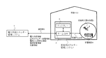
以下、図1乃至図5を参照して、本発明の実施形態について具体的に説明する。図1に
本発明の実施形態の需要家エネルギー管理システムの構成を示す。家庭用エネルギー管理
システム(需要家エネルギー管理システム)1は、情報の送受信を行うホームゲートウェ
イ(ホームG/W)2と、ホームゲートウェイ2が送受信した情報、及び、後述するホー
ムゲートウェイ2において計算を行った結果に関する情報を表示するディスプレー3とを
有する。
Hereinafter, embodiments of the present invention will be specifically described with reference to FIGS. 1 to 5. FIG. 1 shows a configuration of a consumer energy management system according to an embodiment of the present invention. A home energy management system (customer energy management system) 1 performs calculations in a home gateway (home G / W) 2 that transmits and receives information, information transmitted and received by the
ホームゲートウェイ2が送受信する情報は、電力系統に関する情報(電力系統情報)、
自然エネルギー発電量の情報(自然エネルギー発電情報)、電気のCO2原単位の情報(電
気CO2原単位情報)、火力発電や原子力発電や水力発電などの発電量の情報(電源発電情
報)、気象情報などである。自然エネルギー発電量の情報は、電力系統に連系された所定
地域範囲の太陽光発電の発電量や風力発電の発電量や、家庭100内の家庭用太陽光発電
5の発電量など自然エネルギーによる発電量の情報、又はその任意の組み合わせの発電量
を含む情報を含む。電源発電情報は、自然エネルギー以外の電源による発電量の情報であ
る。電気のCO2原単位の情報(電気CO2原単位情報)は、家庭100に供給される電力の全
ての種類のCO2原単位の情報であり、火力発電、水力発電、原子力発電、太陽光発電、家
庭用太陽光発電、風力発電などの種類のCO2原単位の情報を含む。
Information transmitted and received by the
Information on natural energy power generation (natural energy power generation information), information on CO2 basic unit of electricity (electrical CO2 basic unit information), information on power generation amount of thermal power generation, nuclear power generation and hydropower generation (power generation information), weather information Etc. The information on the amount of natural energy generated is based on the amount of natural energy such as the amount of power generated by solar power generation, the amount of wind power generated in a predetermined area connected to the power grid, and the amount of power generated by the home solar power generation 5 in the home 100. Information on the amount of power generation, or information including the amount of power generation in any combination thereof is included. The power generation information is information on the amount of power generated by a power source other than natural energy. Electricity CO2 basic unit information (electrical CO2 basic unit information) is information on all types of CO2 basic unit of electricity supplied to the household 100. Thermal power generation, hydroelectric power generation, nuclear power generation, solar power generation, household Includes information on CO2 basic units such as solar power generation and wind power generation.
ホームゲートウェイ2は、電力系統側の電力系統エネルギー管理システム7から通信線
8を介して情報を受け取る。また、ホームゲートウェイ2は、電力量計(スマートメータ
)を経由して、情報を受け取ることが可能である。また、ホームゲートウェイ2は、情報
モデムを経由して、情報を受け取ることが可能である。ホームゲートウェイ2が受信した
自然エネルギー発電量や電気のCO2原単位などの情報は、ディスプレー3において表示す
る。さらに、ホームゲートウェイ2は、家庭内LAN6により家電機器4や家庭用太陽光
発電(PV)5などのエネルギー機器と情報を交換できる機能を有する。
The
図2は、ホームゲートウェイ2が受け取る電力のCO2原単位の情報、及び、自然エネル
ギー発電量の情報の例を示している。図2(a)は電力のCO2原単位の情報の例を示し、
図2(b)は自然エネルギー発電量の情報の例を示している。図2に示すように、ホーム
ゲートウェイ2では情報を1日のトレンドとして受け取る。このように情報を1日のトレ
ンドとして受け取ると、1日の中で最も低炭素な電力の時刻を知ることができる。なお、
ホームゲートウェイ2は、情報を、瞬時、瞬時の値として受け取ることも可能である。
FIG. 2 shows an example of information on the CO2 basic unit of power received by the
FIG. 2B shows an example of information on the amount of generated natural energy. As shown in FIG. 2, the
The
図3は、ディスプレー3の情報の表示例を示している。図3の例では、風力発電と太陽
光発電の発電量を表示する例を示している。発電量の全体の枠は、100%出力時の発電容量
を表している。この例では、風力発電の方が太陽光発電より容量が少し大きいことを示し
ており、風力発電の100%出力時の発電容量は「**万kW」、太陽光発電の100%出力時の
発電容量は「++万kW」である。その中の塗りつぶしてある部分が現在の発電量を表す
。△印の表示は、出力の平均値(出力平均)を表している。風力発電では、平均出力は、
最大容量の20%程度が多い。太陽光発電では平均出力は最大容量の10%程度となる。
FIG. 3 shows a display example of information on the
There are many about 20% of the maximum capacity. In solar power generation, the average output is about 10% of the maximum capacity.
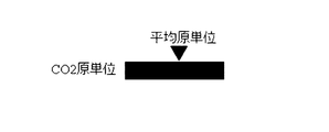
図4は、ディスプレー3の情報のその他の表示例である。図4の例では、電力のCO2原
単位の情報を表示している。△印の表示は、平均の電力のCO2原単位(平均原単位)であ
る。
FIG. 4 is another display example of information on the
なお、ホームゲートウェイ2において、自然エネルギー発電量を、火力発電や原子力発
電を含めた全体の発電量に対する割合(自然エネルギー利用率)として計算し、ディスプ
レー3には、ホームゲートウェイ2により計算された結果を、自然エネルギーの利用率の
予測値として表示することも可能である。ホームゲートウェイ2は、自然エネルギー利用
率の予測値を、以下の式(1)を用いて計算する。

・・・式(1)
また、ディスプレー3は、積算自然エネルギー利用率またはCO2原単位の過去1日または
適当な期間の積算値を表示することも可能である。この場合、ホームゲートウェイ2は、
積算自然エネルギー利用率またはCO2原単位の過去1日または適当な期間の積算値の予測値
を、以下の式(2)を用いて計算する。
... Formula (1)
In addition, the
Use the following formula (2) to calculate the predicted value of the integrated natural energy utilization rate or the integrated value of CO2 basic unit for the past day or appropriate period.
・・・式(2)
また、当該需要家に家庭用太陽発電などの太陽光発電がある場合には、それを考慮して
、自然エネルギー利用率やCO2原単位を計算し、ディスプレー3において表示することが
可能である。その場合、ホームゲートウェイ2は、自然エネルギー利用率の予測値を、以
下の式(3)を用いて計算する。
... Formula (2)
In addition, when the consumer has solar power generation such as household solar power generation, it is possible to calculate the natural energy utilization rate and CO2 basic unit and display it on the
・・・式(3)
また、ホームゲートウェイ2は、家電機器4など家庭100内において使用される電力
のCO2原単位の予測値を、以下の式(4)を用いて計算する。ここで、当該需要家に家庭
用太陽光発電などの太陽光発電がある場合には、それを考慮して、家庭100内において
使用される電力のCO2原単位の予測値を計算する。
... Formula (3)
Moreover, the
・・・式(4)
また、図には表示していないが、自然エネルギー発電量が標準値より大きくなる程度や
CO2原単位が標準値より小さくなる程度に応じて、ディスプレー3に、電力の使用を促す
コメントを表示することも可能である。即ち、自然エネルギーが極めて豊富、または、CO
2原単位が極めて低ければ、電力量に余裕があり現在の電力使用量に対して更に使用可能
である旨(或いは、電力をふんだんに使うことを進める旨)のメッセージをディスプレー
3に表示する。逆に、自然エネルギー発電が普通より少ない、または、CO2原単位が平均
より高いときには、節電を促す旨のメッセージをディスプレー3に表示する。この際、ホ
ームゲートウェイ2は、自然エネルギー発電量、または、自然エネルギー利用率、または
、CO2原単位の所定期間の平均値と、現在の自然エネルギー発電量、または、現在の自
然エネルギー利用率、または、現在のCO2原単位を比較し、その大小に応じて上述した
メッセージを作成する。ディスプレー3は、ホームゲートウェイ2により作成されたメッ
セージを表示する。
... Formula (4)
Although not shown in the figure, the extent to which the amount of renewable energy generated is greater than the standard value.
Depending on the extent to which the CO2 basic unit becomes smaller than the standard value, it is possible to display a comment prompting the use of power on the
2 If the basic unit is extremely low, a message is displayed on the
次に、家庭用エネルギー管理システム1が、気象情報に基づく気象条件から需要家自身
を含む地域の自然エネルギー発電量または地域電力のCO2原単位を予測し、家電製品4の
運用スケジュールを、一日のCO2発生量が最も少なくなるか、または自然エネルギー使用
率の最も高くなるように決定する動作について述べる。
Next, the home energy management system 1 predicts the amount of natural energy generated in the region including the customer itself or the CO2 basic unit of the local power from the weather conditions based on the weather information, and sets the operation schedule of the home appliance 4 for one day. The operation to determine the lowest CO2 emission or the highest natural energy usage rate will be described.
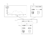
図5に、家庭用エネルギー管理システム1の家電機器4の運用スケジュールの決定処理
の動作例を示す。家庭用エネルギー管理システム1のホームゲートウェイ2には、自動的
に運用スケジュールの対象とする家電機器4を選択する機能、スケジュールして良い時間
範囲を指定する機能、電力の自然エネルギー率やCO2原単位の予測を入力する機能、家電
機器4の運用スケジュールを出力する機能を持つ。
In FIG. 5, the operation example of the determination process of the operation schedule of the household appliances 4 of the household energy management system 1 is shown. The
ホームゲートウェイ2は、上述したように式(4)を用いて計算したCO2原単位情報5
1と、ホームゲートウェイ2内に記憶されているスケジュール可能な家電情報52に基づ
いて、家電運用スケジュール53を計算する。ホームゲートウェイ2において、家電運用
スケジュール53を計算するための家電機器4のスケジューリングアルゴリズムは、一般
には非線形最適化法または総当り計算、またはその組み合わせを適用する。ホームゲート
ウェイ2は、計算した家電運用スケジュール53に基づいて、家庭内LAN6を活用して家
電機器4を自動制御することが可能である。
The
1 and a home
ここで、CO2原単位情報51は、家庭100内において使用される電力の一日分のCO2原
単位の情報である。スケジュール可能な家電情報52は、スケジュール可能な家電機器と
、このスケジュール可能な家電機器の各々についてスケジュール可能な時間帯を示してい
る。図5の例では、スケジュール可能な家電機器として「エアコン」、「食洗機」、「洗
濯機」等が示されており、これらの家電機器は、ホームゲートウェイ2が運用スケジュー
ルの対象として選択可能なものである。また、スケジュール可能な時間帯として、「エア
コン」は「10時〜16時」、「食洗機」は「22時〜4時」、「洗濯機」は「8時〜1
6時」であることを示しており、ホームゲートウェイ2は、これらの家電機器について、
スケジュール可能な時間帯の範囲内にてスケジュールして良い時間範囲を指定することが
可能である。
Here, the CO2 basic unit information 51 is information on the CO2 basic unit for one day of electric power used in the home 100. The schedulable home appliance information 52 indicates a schedulable home appliance and a schedulable time zone for each of the schedulable home appliances. In the example of FIG. 5, “air conditioner”, “dishwasher”, “washing machine”, etc. are shown as household appliances that can be scheduled, and these household appliances can be selected by the
6 o'clock ", and the
It is possible to specify a time range that can be scheduled within the range of the schedule time zone.
家電運用スケジュール53は、運用対象とする家電機器と、この運用対象の家電機器の
各々についての運用計画を示している。図5の例では、運用対象の家電機器として「エア
コン」、「食洗機」、「洗濯機」等が示されている。また、運用計画として、「エアコン
」は「10時〜16時」、「食洗機」は「22時〜23時」、「洗濯機」は「12時〜1
3時」の時間帯に運用を行うよう制御することを示している。
The home
This indicates that the control is performed so that the operation is performed in the “3 o'clock” time zone.
また、ディスプレー3は、ホームゲートウェイ2により計算された家電運用スケジュー
ル53の表示や、利用者に対するアドバイスに関するメッセージの表示、節約できるCO2
発生量の表示等を行う。
In addition, the
The amount generated is displayed.
このように本発明の実施形態によれば、自然エネルギー発電量や電気のCO2原単位など
の情報、自然エネルギー利用率、積算自然エネルギー利用率、家庭内において使用される
電力のCO2原単位などの表示、または、一日のCO2発生量が最も少なくなるか、または自然
エネルギー使用率の最も高くなるように運用スケジュールを計算し、家電製品を制御する
ことにより、需要家のCO2発生量を大幅に削減することができる。
As described above, according to the embodiment of the present invention, information such as the amount of natural energy generated and the CO2 basic unit of electricity, the natural energy utilization rate, the integrated natural energy utilization rate, the CO2 basic unit of electric power used in the home, and the like. Display or calculate the operation schedule so that the amount of CO2 generation per day is the lowest or the highest usage rate of natural energy, and control consumer electronics to significantly increase the amount of CO2 generated by consumers Can be reduced.
したがって、豊富に存在するにもかかわらず天候や太陽位置に大きく依存し、不安定で
あるために、電力系統への導入が遅れている自然エネルギーを有効に利用し、需要家のCO
2発生量を大幅に削減することが可能となる。
Therefore, even though it is abundant, it relies heavily on the weather and solar position and is unstable.
2 It is possible to greatly reduce the amount generated.
1…家庭用エネルギー管理システム、2…ホームゲートウェイ、3…ディスプレー、4
…家電機器、5…家庭用太陽光発電、6…家庭内LAN、7…電力系統エネルギー管理シ
ステム、8…通信線、51…CO2原単位情報、52…スケジュール可能な家電情報、53
…家電運用スケジュール情報、100…家庭。
1 ... Home energy management system, 2 ... Home gateway, 3 ... Display, 4
... Home appliances, 5 ... Home solar power generation, 6 ... Home LAN, 7 ... Power system energy management system, 8 ... Communication line, 51 ... CO2 basic unit information, 52 ... Scheduled home appliance information, 53
... home appliance operation schedule information, 100 ... home.
Claims (10)
け取るホームゲートウェイと、
前記ホームゲートウェイにより受け取られた前記自然エネルギー発電情報または電力の
CO2原単位の情報を表示するディスプレーを具備することを特徴とする需要家エネルギ
ー管理システム。 A home gateway that receives at least renewable energy generation information or CO2 basic unit information linked to the power system;
A consumer energy management system comprising a display for displaying the natural energy power generation information received by the home gateway or the CO2 basic unit information of electric power.
太陽光発電、風力発電、家庭用太陽光発電のいずれかの発電量、または、その任意の組み
合わせの発電量を含む情報を受け取ることを特徴とする請求項1記載の需要家エネルギー
管理システム。 The home gateway receives, as the natural energy power generation information, information including at least a power generation amount of any one of a predetermined region of solar power generation, wind power generation, home solar power generation, or any combination thereof. The customer energy management system according to claim 1.
ルギー利用率、電力のCO2原単位のいずれか1つを表示することを特徴とする請求項1
記載の需要家エネルギー管理システム。 2. The display according to claim 1, wherein at least one of power type, total natural energy generation amount, natural energy utilization rate, and CO2 basic unit of electric power is displayed.
The customer energy management system described.
要家の管理下にある自然エネルギー発電を加味して計算し、
前記ディスプレーは、前記ホームゲートウェイにおいて計算された需要家の管理下にあ
る自然エネルギー発電を加味した自然エネルギー発電量、または、電力のCO2原単位を
表示する
ことを特徴とする請求項3記載の需要家エネルギー管理システム。 The home gateway calculates a natural energy power generation amount or CO2 basic unit of electric power in consideration of a natural energy power generation under the control of a consumer,
4. The demand according to claim 3, wherein the display displays a natural energy generation amount that takes into account a natural energy generation under the control of a consumer calculated in the home gateway, or a CO2 basic unit of electric power. Home energy management system.
電力のCO2原単位のいずれか1つについて一定期間にわたり積算、または、平均を計算
し、
前記ディスプレーは、前記ホームゲートウェイにより計算された自然エネルギー利用率
、電力のCO2原単位のいずれかの積算、または、平均を表示する
ことを特徴とする請求項3記載の需要家エネルギー管理システム。 The home gateway has at least a natural energy generation amount, a natural energy utilization rate,
Accumulate or calculate an average over a period of time for any one of the CO2 basic units of electricity,
The consumer energy management system according to claim 3, wherein the display displays a natural energy utilization rate calculated by the home gateway, an integration of any of CO2 basic units of electric power, or an average.
原単位のいずれか1つの所定期間の平均値を表示することを特徴とする請求項3乃至5の
いずれか1項に記載の需要家エネルギー管理システム。 The display includes at least a natural energy generation amount, a natural energy utilization rate, CO2
The consumer energy management system according to any one of claims 3 to 5, wherein an average value of any one of the basic units for a predetermined period is displayed.
たは、CO2原単位の所定期間の平均値と、現在の自然エネルギー発電量、または、現在
の自然エネルギー利用率、または、現在のCO2原単位を比較し、その比較結果に応じた
メッセージを作成し、
前記ディスプレーは、前記ホームゲートウェイにより作成された前記メッセージを表示
する
ことを特徴とする請求項3乃至6のいずれか1項に記載の需要家エネルギー管理システ
ム。 The home gateway includes a natural energy generation amount, a natural energy utilization rate, or an average value of a CO2 basic unit for a predetermined period, a current natural energy generation amount, a current natural energy utilization rate, or a current Compare CO2 basic units, create a message according to the comparison result,
The consumer energy management system according to any one of claims 3 to 6, wherein the display displays the message created by the home gateway.
、当該地域電力のCO2原単位に基づいて家電製品の運用スケジュールを計算するホーム
ゲートウェイと、
前記ホームゲートウェイにより計算された前記家電製品の運用スケジュールを表示する
ディスプレーと
を具備することを特徴とする需要家エネルギー管理システム。 A home gateway that inputs meteorological information, calculates the amount of renewable energy generated in the area or CO2 basic unit of local power, and calculates the operation schedule of home appliances based on the CO2 basic unit of the local power;
A consumer energy management system comprising: a display that displays an operation schedule of the home appliance calculated by the home gateway.
期間の自然エネルギー使用率が最も高くなる運用スケジュールを計算するアルゴリズムを
用いて、家電製品の運用スケジュールを計算し、
前記ディスプレーは、前記ホームゲートウェイにて計算された前記家電製品の運用スケ
ジュールを表示する
ことを特徴とする請求項6記載の需要家エネルギー管理システム。 The home gateway calculates an operation schedule of home appliances using an algorithm that calculates an operation schedule in which the amount of CO2 generated in a predetermined period is the smallest or the natural energy usage rate in the predetermined period is the highest,
The consumer energy management system according to claim 6, wherein the display displays an operation schedule of the home appliance calculated by the home gateway.
ール可能な家電機器の各々のスケジュール可能な時間帯を示すスケジュール可能な家電情
報に基づいて、家電製品の運用スケジュールを計算することを特徴とする請求項6又は7
に記載の需要家エネルギー管理システム。 The home gateway calculates an operation schedule of home appliances based on pre-stored schedulable home appliances and schedulable home appliance information indicating each schedulable home appliance. Claim 6 or 7 characterized
The consumer energy management system described in.
Priority Applications (5)
| Application Number | Priority Date | Filing Date | Title |
|---|---|---|---|
| JP2010223203A JP2012080664A (en) | 2010-09-30 | 2010-09-30 | User energy management system |
| US13/246,393 US20120083938A1 (en) | 2010-09-30 | 2011-09-27 | Consumer Energy Management System |
| BRPI1106788-8A BRPI1106788A2 (en) | 2010-09-30 | 2011-09-29 | Consumer Power Management System |
| CN2011103053331A CN102545203A (en) | 2010-09-30 | 2011-09-30 | Consumer Energy Management System |
| JP2014059163A JP2014147285A (en) | 2010-09-30 | 2014-03-20 | User energy management system |
Applications Claiming Priority (1)
| Application Number | Priority Date | Filing Date | Title |
|---|---|---|---|
| JP2010223203A JP2012080664A (en) | 2010-09-30 | 2010-09-30 | User energy management system |
Related Child Applications (1)
| Application Number | Title | Priority Date | Filing Date |
|---|---|---|---|
| JP2014059163A Division JP2014147285A (en) | 2010-09-30 | 2014-03-20 | User energy management system |
Publications (2)
| Publication Number | Publication Date |
|---|---|
| JP2012080664A true JP2012080664A (en) | 2012-04-19 |
| JP2012080664A5 JP2012080664A5 (en) | 2014-03-13 |
Family
ID=45890498
Family Applications (2)
| Application Number | Title | Priority Date | Filing Date |
|---|---|---|---|
| JP2010223203A Pending JP2012080664A (en) | 2010-09-30 | 2010-09-30 | User energy management system |
| JP2014059163A Pending JP2014147285A (en) | 2010-09-30 | 2014-03-20 | User energy management system |
Family Applications After (1)
| Application Number | Title | Priority Date | Filing Date |
|---|---|---|---|
| JP2014059163A Pending JP2014147285A (en) | 2010-09-30 | 2014-03-20 | User energy management system |
Country Status (4)
| Country | Link |
|---|---|
| US (1) | US20120083938A1 (en) |
| JP (2) | JP2012080664A (en) |
| CN (1) | CN102545203A (en) |
| BR (1) | BRPI1106788A2 (en) |
Cited By (3)
| Publication number | Priority date | Publication date | Assignee | Title |
|---|---|---|---|---|
| JP2014027721A (en) * | 2012-07-24 | 2014-02-06 | Toshiba Corp | Energy management system, energy management device, control method, and program |
| KR101434296B1 (en) | 2012-06-18 | 2014-08-29 | 중앙대학교 산학협력단 | Apparatus and method for monitoring amount of energy consumption in apartment housing |
| JP2020170484A (en) * | 2019-04-05 | 2020-10-15 | 株式会社日立製作所 | Electric power energy source management device and method |
Families Citing this family (14)
| Publication number | Priority date | Publication date | Assignee | Title |
|---|---|---|---|---|
| CN103576633A (en) * | 2012-08-09 | 2014-02-12 | 海尔集团公司 | Method and system for conducting power supply control on intelligent home systems in community micro grid |
| US9728964B2 (en) | 2013-03-15 | 2017-08-08 | Vivint, Inc. | Power production monitoring or control |
| CN103390904B (en) * | 2013-07-18 | 2015-11-25 | 国家电网公司 | Regenerative resource is generated electricity by way of merging two or more grid systems analytical method |
| KR20170013743A (en) * | 2015-07-28 | 2017-02-07 | 엘에스산전 주식회사 | Remote monitoring system for monitoring renewable energy generating apparatus |
| CN105373009A (en) * | 2015-11-12 | 2016-03-02 | 中国人民解放军国防科学技术大学 | Renewable energy system simulation test and semi-physical simulation system |
| CN106230009B (en) * | 2016-08-30 | 2018-09-14 | 深圳耐斯特思新能源科技有限公司 | A kind of Energy Management System and method of family energy storaging product |
| CN109213019A (en) * | 2017-06-29 | 2019-01-15 | 青岛恒金源电子科技有限公司 | Wired home renewable sources of energy condition monitoring system |
| DE102018112058A1 (en) * | 2018-04-01 | 2019-10-02 | RS Utility Service UG (haftungsbeschränkt) | Data processing unit, control unit and method for controlling the amount of electrical grid energy absorbed |
| JP2021022118A (en) * | 2019-07-26 | 2021-02-18 | トヨタ自動車株式会社 | Advertisement display management system |
| JP7438029B2 (en) | 2020-06-08 | 2024-02-26 | 三菱重工業株式会社 | energy management system |
| EP3937112A1 (en) * | 2020-07-06 | 2022-01-12 | Karl Kull | Method for energy consumption management based on the principle of primary energy share in the system |
| US11835246B2 (en) | 2021-06-17 | 2023-12-05 | Google Llc | Managing user account participation in emissions demand response events |
| US20220404050A1 (en) * | 2021-06-17 | 2022-12-22 | Google Llc | Dynamic adaptation of emissions demand response events |
| CN115015474B (en) * | 2022-04-15 | 2023-06-23 | 广东电网有限责任公司 | Method and equipment for detecting carbon emission of power consumer |
Citations (9)
| Publication number | Priority date | Publication date | Assignee | Title |
|---|---|---|---|---|
| JP2006309325A (en) * | 2005-04-26 | 2006-11-09 | Ohrin Planning:Kk | Co2 reduction and power saving monitoring method, and its system |
| JP2007185083A (en) * | 2005-12-06 | 2007-07-19 | Toyota Motor Corp | Charging system and electric vehicle |
| JP2008289276A (en) * | 2007-05-17 | 2008-11-27 | Nippon Telegr & Teleph Corp <Ntt> | Apparatus controller, apparatus control system and apparatus control method |
| JP2009070083A (en) * | 2007-09-12 | 2009-04-02 | Nec Corp | Carbon-dioxide emission reduction system and method for reducing carbon-dioxide emission |
| JP2010028879A (en) * | 2008-07-15 | 2010-02-04 | Hitachi Ltd | Method of inducing power demand and its system |
| WO2010019235A1 (en) * | 2008-08-12 | 2010-02-18 | Efficiency 2.0, Llc | Methods and apparatus for greenhouse gas footprint monitoring |
| US20100106575A1 (en) * | 2008-10-28 | 2010-04-29 | Earth Aid Enterprises Llc | Methods and systems for determining the environmental impact of a consumer's actual resource consumption |
| JP2012019652A (en) * | 2010-07-09 | 2012-01-26 | Sony Corp | Apparatus and method for controlling power |
| JP2012019653A (en) * | 2010-07-09 | 2012-01-26 | Sony Corp | Apparatus and method for controlling electric power |
Family Cites Families (4)
| Publication number | Priority date | Publication date | Assignee | Title |
|---|---|---|---|---|
| JP2005135206A (en) * | 2003-10-31 | 2005-05-26 | Hitachi Ltd | Energy management program |
| US7274975B2 (en) * | 2005-06-06 | 2007-09-25 | Gridpoint, Inc. | Optimized energy management system |
| US20100287012A1 (en) * | 2008-04-08 | 2010-11-11 | Bloom Energy Corporation | Method and system for measuring carbon dioxide reduction |
| JP5355147B2 (en) * | 2009-02-27 | 2013-11-27 | 株式会社東芝 | Emission factor calculator and emission factor calculation method |
-
2010
- 2010-09-30 JP JP2010223203A patent/JP2012080664A/en active Pending
-
2011
- 2011-09-27 US US13/246,393 patent/US20120083938A1/en not_active Abandoned
- 2011-09-29 BR BRPI1106788-8A patent/BRPI1106788A2/en not_active Application Discontinuation
- 2011-09-30 CN CN2011103053331A patent/CN102545203A/en active Pending
-
2014
- 2014-03-20 JP JP2014059163A patent/JP2014147285A/en active Pending
Patent Citations (9)
| Publication number | Priority date | Publication date | Assignee | Title |
|---|---|---|---|---|
| JP2006309325A (en) * | 2005-04-26 | 2006-11-09 | Ohrin Planning:Kk | Co2 reduction and power saving monitoring method, and its system |
| JP2007185083A (en) * | 2005-12-06 | 2007-07-19 | Toyota Motor Corp | Charging system and electric vehicle |
| JP2008289276A (en) * | 2007-05-17 | 2008-11-27 | Nippon Telegr & Teleph Corp <Ntt> | Apparatus controller, apparatus control system and apparatus control method |
| JP2009070083A (en) * | 2007-09-12 | 2009-04-02 | Nec Corp | Carbon-dioxide emission reduction system and method for reducing carbon-dioxide emission |
| JP2010028879A (en) * | 2008-07-15 | 2010-02-04 | Hitachi Ltd | Method of inducing power demand and its system |
| WO2010019235A1 (en) * | 2008-08-12 | 2010-02-18 | Efficiency 2.0, Llc | Methods and apparatus for greenhouse gas footprint monitoring |
| US20100106575A1 (en) * | 2008-10-28 | 2010-04-29 | Earth Aid Enterprises Llc | Methods and systems for determining the environmental impact of a consumer's actual resource consumption |
| JP2012019652A (en) * | 2010-07-09 | 2012-01-26 | Sony Corp | Apparatus and method for controlling power |
| JP2012019653A (en) * | 2010-07-09 | 2012-01-26 | Sony Corp | Apparatus and method for controlling electric power |
Cited By (4)
| Publication number | Priority date | Publication date | Assignee | Title |
|---|---|---|---|---|
| KR101434296B1 (en) | 2012-06-18 | 2014-08-29 | 중앙대학교 산학협력단 | Apparatus and method for monitoring amount of energy consumption in apartment housing |
| JP2014027721A (en) * | 2012-07-24 | 2014-02-06 | Toshiba Corp | Energy management system, energy management device, control method, and program |
| JP2020170484A (en) * | 2019-04-05 | 2020-10-15 | 株式会社日立製作所 | Electric power energy source management device and method |
| JP7333191B2 (en) | 2019-04-05 | 2023-08-24 | 株式会社日立製作所 | Power-derived management device and method |
Also Published As
| Publication number | Publication date |
|---|---|
| CN102545203A (en) | 2012-07-04 |
| US20120083938A1 (en) | 2012-04-05 |
| JP2014147285A (en) | 2014-08-14 |
| BRPI1106788A2 (en) | 2015-06-02 |
Similar Documents
| Publication | Publication Date | Title |
|---|---|---|
| JP2014147285A (en) | User energy management system | |
| Zhou et al. | Smart home energy management systems: Concept, configurations, and scheduling strategies | |
| Weranga et al. | Smart Metering Applications | |
| Tascikaraoglu et al. | A demand side management strategy based on forecasting of residential renewable sources: A smart home system in Turkey | |
| JP5578524B2 (en) | Power input / output management system and server device and distribution board therefor | |
| Li et al. | Techno-economic performance analysis of zero energy house applications with home energy management system in Japan | |
| JP2012094077A (en) | Household energy management system | |
| JP2010204833A (en) | Energy management system and method | |
| EP2494736B1 (en) | Method of controlling network system | |
| US20120203391A1 (en) | Network system and method of controlling the same | |
| KR20160010789A (en) | Economic Electrical Power Supply Method for Micro Grid based on New Renewable Energy and ESS using the same | |
| Nayanatara et al. | Micro-grid management strategy with the integration of renewable energy using IoT | |
| Baldauf | A smart home demand-side management system considering solar photovoltaic generation | |
| Tascikaraoglu et al. | Smart grid-ready concept of a smart home prototype: A demonstration project in YTU | |
| Al Essa | Energy assessments of a photovoltaic-wind-battery system for residential appliances in Iraq | |
| US20120204044A1 (en) | Method of controlling network system | |
| Fiorini et al. | Predictive multi-objective scheduling with dynamic prices and marginal CO2-emission intensities | |
| US9851734B2 (en) | Alert presentation apparatus and alert presentation method | |
| JP6054737B2 (en) | Method and apparatus for predicting transition of power storage amount | |
| JP5940263B2 (en) | Power control apparatus and power control method | |
| KR101015133B1 (en) | Control system for electric home appliance associated with photovoltaic generation system | |
| TWI441409B (en) | System for monitoring electricity | |
| Ku et al. | Demand response operation method on energy big data platform | |
| Cesena et al. | Energy efficiency at the building and district levels in a multi-energy context | |
| KR101619961B1 (en) | Method for controlling an electric appliance |
Legal Events
| Date | Code | Title | Description |
|---|---|---|---|
| A621 | Written request for application examination |
Free format text: JAPANESE INTERMEDIATE CODE: A621 Effective date: 20130227 |
|
| A977 | Report on retrieval |
Free format text: JAPANESE INTERMEDIATE CODE: A971007 Effective date: 20140115 |
|
| A521 | Request for written amendment filed |
Free format text: JAPANESE INTERMEDIATE CODE: A523 Effective date: 20140128 |
|
| A131 | Notification of reasons for refusal |
Free format text: JAPANESE INTERMEDIATE CODE: A131 Effective date: 20140214 |
|
| A02 | Decision of refusal |
Free format text: JAPANESE INTERMEDIATE CODE: A02 Effective date: 20140613 |