JP2012075009A - Redundancy device and redundancy program - Google Patents
Redundancy device and redundancy program Download PDFInfo
- Publication number
- JP2012075009A JP2012075009A JP2010219349A JP2010219349A JP2012075009A JP 2012075009 A JP2012075009 A JP 2012075009A JP 2010219349 A JP2010219349 A JP 2010219349A JP 2010219349 A JP2010219349 A JP 2010219349A JP 2012075009 A JP2012075009 A JP 2012075009A
- Authority
- JP
- Japan
- Prior art keywords
- communication
- redundancy
- monitoring
- server
- communication means
- Prior art date
- Legal status (The legal status is an assumption and is not a legal conclusion. Google has not performed a legal analysis and makes no representation as to the accuracy of the status listed.)
- Pending
Links
Images


Abstract
Description
本発明は、冗長化装置及び冗長化プログラムに関し、例えばクラスタ構成をとるサーバ間でネットワークを直結した場合に、サーバのネットワークデバイスの冗長化を実現する冗長化装置及びプログラムに適用し得るものである。 The present invention relates to a redundancy apparatus and a redundancy program, and can be applied to a redundancy apparatus and a program for realizing redundancy of a network device of a server when a network is directly connected between servers having a cluster configuration, for example. .
一般的に、システムの信頼性を向上させるために、通信機器を使用するサーバは、現用系サーバと待機系サーバとを組み合わせたHA(High Availability)クラスタシステムを採用することが多い。 In general, in order to improve the reliability of the system, a server using a communication device often employs an HA (High Availability) cluster system in which an active server and a standby server are combined.
HAクラスタシステムでは、各サーバが、相手サーバの死活監視及びデータ同期を行うために、プライベートLANにてサーバ間を接続するのが一般的である。このサーバ間のLAN接続をインターコネクトLANと呼んでいる。 In an HA cluster system, it is common for each server to connect between servers via a private LAN in order to perform alive monitoring and data synchronization of the other server. This LAN connection between servers is called an interconnect LAN.
インターコネクトLANは、サーバ間で多量なデータをやり取りするため、他のサーバのデータ通信の影響を受けないようにする必要があり、サーバ間に専用のネットワーク装置(例えば、NWスイッチなど)を配置させたり、若しくは、サーバ間を直結して接続したりするケースが多く採用されている。 Since the interconnect LAN exchanges a large amount of data between servers, it is necessary not to be affected by the data communication of other servers, and a dedicated network device (for example, an NW switch) is arranged between the servers. In many cases, the servers are connected directly to each other.
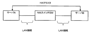
例えば、図2は、NWスイッチを用いたインターコネクトLANの接続構成例を示す構成図であり、図3は、サーバ間を直結したインターコネクトLANの接続構成例を示す構成図である。 For example, FIG. 2 is a configuration diagram illustrating an example of a connection configuration of an interconnect LAN using an NW switch, and FIG. 3 is a configuration diagram illustrating an example of a connection configuration of an interconnect LAN in which servers are directly connected.
図2において、インターコネクトLANは、HAクラスタ構成をとるサーバAとサーバBとの間に、NWスイッチSWが置かれる。サーバA及びサーバBは、NWスイッチSWを介して、相手サーバとの間でデータ授受を行うことで、相手サーバの死活監視やデータ同期を実現する。 In FIG. 2, in the interconnect LAN, an NW switch SW is placed between a server A and a server B having an HA cluster configuration. The server A and the server B perform life monitoring and data synchronization of the partner server by exchanging data with the partner server via the NW switch SW.
図3に例示するインターコネクトLANは、NWスイッチを介在させることなく、サーバAとサーバBとに直結してデータ授受を行う。つまり、各サーバのネットワークデバイスは、NWスイッチを介さず、直接相手サーバのNWデバイスとデータ授受を行う。 The interconnect LAN illustrated in FIG. 3 transmits and receives data directly connected to the server A and the server B without interposing an NW switch. That is, the network device of each server directly exchanges data with the NW device of the partner server without going through the NW switch.
また、特許文献1には、ネットワークの障害耐性を高めるために、運用リンクと予備リンクとを設けて、ネットワークに対する冗長性を付与する技術が記載されている。
上述したように、図2に例示したNWスイッチを用いたインターコネクトLANを構成する場合、サーバ間にNWスイッチSWを置くことが必要なので、その分コストが増加するという問題が生じ得る。また、NWスイッチSWの障害発生も生じ得るので、NWスイッチSWの障害によるシステムの信頼性の低下という問題も生じ得る。 As described above, when the interconnect LAN using the NW switch illustrated in FIG. 2 is configured, since it is necessary to place the NW switch SW between the servers, there is a problem that the cost increases correspondingly. In addition, since the failure of the NW switch SW may occur, there may be a problem that the reliability of the system is lowered due to the failure of the NW switch SW.
また、図3に例示したサーバ間を直結したインターコネクタLANを構成する場合、NWスイッチを置く必要がないので、その分コストを抑えることはできる。しかし、サーバが複数のネットワークデバイス(例えばNIC等)を備えて、ネットワークデバイスの冗長化を実現する際に、次のような問題が生じ得る。 Further, when the interconnector LAN in which the servers illustrated in FIG. 3 are directly connected is configured, it is not necessary to place an NW switch, so that the cost can be reduced accordingly. However, when the server includes a plurality of network devices (for example, NICs) and realizes redundancy of the network devices, the following problems may occur.
例えば、Linux(登録商標)の場合、ネットワークデバイスの冗長化は、カーネルのモジュールであるbondingモジュールというソフトウェアを使用して行う。bondingは、複数のネットワークデバイスを監視し、正常に動作するネットワークデバイスを選択し、ネットワークデバイスの障害時には他のネットワークデバイスに切り替える機能である。 For example, in the case of Linux (registered trademark), network device redundancy is performed using software called a bonding module, which is a kernel module. Bonding is a function that monitors a plurality of network devices, selects a normally operating network device, and switches to another network device when a network device fails.
bondingによるネットワークデバイスの監視方式には、ARP監視方式とMIIリンク監視方式とがある。ARP監視方式は、指定したIPアドレスに対して定期的にARPパケット(ARP信号)を送信し、その応答の受信に基づいて障害の有無を監視する方法である。一方、MIIリンク監視方式は、ネットワークデバイスのポートリンクのリンク状態に基づいて障害の有無を監視する方法である。 Network device monitoring methods based on bonding include an ARP monitoring method and an MII link monitoring method. The ARP monitoring method is a method of periodically transmitting an ARP packet (ARP signal) to a specified IP address and monitoring the presence or absence of a failure based on reception of the response. On the other hand, the MII link monitoring method is a method of monitoring the presence or absence of a failure based on the link state of the port link of the network device.
図4は、bondingにおけるARP監視方式を説明する説明図である。図4に示すように、bondingにおけるARP監視は、ARPカウンタを用いて、ARPパケットの送達確認を行う。 FIG. 4 is an explanatory diagram for explaining an ARP monitoring method in bonding. As shown in FIG. 4, ARP monitoring in bonding performs ARP packet delivery confirmation using an ARP counter.
例えば、図4において、サーバA及びサーバBは、それぞれ2つのネットワークデバイス(NWデバイス)10A−1〜10A−2及び10B−1〜10B−2を有する。サーバAのNWデバイス10A−1は、サーバBのNWデバイス10B−1とLAN接続している。bondingにおけるARP監視の場合、NWデバイス10A−1とNWデバイス10B−1との間で、定期的にARPパケットが送受信される。
For example, in FIG. 4, server A and server B have two network devices (NW devices) 10A-1 to 10A-2 and 10B-1 to 10B-2, respectively. The
このとき、NWデバイス10A−1及び10B−1のNWデバイスドライバは、ARPパケットが送受信されるたびに、ARPカウンタ20A−1及び20B−1のカウンタ値を更新する。
At this time, the NW device drivers of the
一方、NWデバイス10A−2及び10B−2のNWデバイスドライバは、ARPカウンタ20A−2及び20B−2のカウンタ値に変動させない。
On the other hand, the NW device drivers of the
各サーバにおいて、bondingは、ARPカウンタを監視しており、カウンタ値の更新がなされている場合には、正常にARPパケットが送受信されており、NWデバイスが正常に動作していることを判断する。従って、図4の例の場合、サーバA及びサーバBにおけるbondingは、カウンタ値が更新されているNWデバイス10A−1及びNWデバイス10B−1を選択して通信を行う。
In each server, bonding monitors the ARP counter. When the counter value is updated, it is determined that the ARP packet has been normally transmitted and received and the NW device is operating normally. . Therefore, in the example of FIG. 4, the bonding in the server A and the server B performs communication by selecting the
しかし、例えばLinuxシステムでのARP監視は、NWデバイスドライバに依存する。つまり、NWデバイスドライバがARPカウンタの更新機能を有している場合には対応できるが、そうでない場合にはARP監視機能を対応することができない。 However, for example, ARP monitoring in the Linux system depends on the NW device driver. That is, the NW device driver can cope with an ARP counter update function, but cannot otherwise cope with an ARP monitoring function.
従来、サーバ間を直結したインターコネクトLANを構成する場合には、ARP監視方式を使用する場合が多い。しかし、上記の理由もあり、bondingを使用する場合には、MIIリンク監視方式を採用することが一般的である。そこで、サーバ間を直結したインターコネクトLANを構成する場合でも、MIIリンク監視方式を採用することが望まれている。 Conventionally, when configuring an interconnect LAN in which servers are directly connected, an ARP monitoring method is often used. However, for the reasons described above, when using bonding, it is common to employ the MII link monitoring method. Therefore, even when an interconnect LAN in which servers are directly connected is configured, it is desired to adopt the MII link monitoring method.
ところが、bondingにおけるMIIリンク監視方式を採用する場合、以下のような課題が生じ得る。 However, when the MII link monitoring method in bonding is adopted, the following problems may occur.
例えば、図5において、サーバAのNWデバイス10A−1とサーバBのNWデバイス10B−1のLANポートがリンクアップしているのに対して、サーバAのNWデバイス10A−2とサーバBのNWデバイス10B−2のLANポートがリンクダウンしている。
For example, in FIG. 5, the
この場合、サーバA及びサーバBにおいて、LANポートがリンクアップしているNWデバイス10A及びNWデバイス10B−1が選択されるが、LANポートがリンクアップしている状態であっても、ネットワークデバイス自体が故障している場合には、NWデバイスの切り替えができず、使用可能なNWデバイスの選択ができないという問題もある。
In this case, in the server A and the server B, the
また、MIIリンク監視方式は、LANポートのリンク状態を監視するものであるから、ポートの先の状態(例えば回線の障害など)を見ることができないという問題もある。 In addition, since the MII link monitoring method monitors the link state of the LAN port, there is a problem that the state of the port (for example, a line failure) cannot be seen.
そのため、LANポートがリンクアップしているネットワークデバイスが故障した場合でも、使用可能なネットワークデバイスへの切り替え及び選択ができる冗長化システム及び冗長化プログラムが求められている。 Therefore, there is a need for a redundancy system and a redundancy program that can switch to and select a usable network device even when a network device with a linked LAN port fails.
かかる課題を解決するために、第1の本発明の冗長化装置は、クラスタシステムを構成する他のサーバとの間でデータ通信を行う複数の通信手段の冗長化を行う冗長化装置において、(1)複数の通信手段のうち、データ通信に使用する通信手段を設定する冗長化設定手段と、(2)複数の通信手段のそれぞれの通信機能を監視する通信監視手段と、(3)通信監視手段によりデータ通信に使用する通信手段の障害が検出されると、冗長化設定手段に対して、他の通信手段への切り替え指示を行う切替指示手段とを備えることを特徴とする。 In order to solve such a problem, a redundancy apparatus according to a first aspect of the present invention is a redundancy apparatus that performs redundancy of a plurality of communication means that perform data communication with other servers that constitute a cluster system. 1) redundancy setting means for setting communication means used for data communication among a plurality of communication means, (2) communication monitoring means for monitoring each communication function of the plurality of communication means, and (3) communication monitoring. When a failure of a communication means used for data communication is detected by the means, a switching instruction means for instructing the redundancy setting means to switch to another communication means is provided.
第2の本発明の冗長化プログラムは、クラスタシステムを構成する他のサーバとの間でデータ通信を行う複数の通信手段の冗長化を行う冗長化プログラムにおいて、コンピュータを、(1)複数の通信手段のうち、データ通信に使用する通信手段を設定する冗長化設定手段、(2)複数の通信手段のそれぞれの通信機能を監視する通信監視手段、(3)通信監視手段によりデータ通信に使用する通信手段の障害が検出されると、冗長化設定手段に対して、他の上記通信手段への切り替え指示を行う切替指示手段として機能させることを特徴とする。 A redundancy program according to a second aspect of the present invention is a redundancy program for redundancy of a plurality of communication means for performing data communication with other servers constituting a cluster system. Among the means, redundancy setting means for setting communication means used for data communication, (2) communication monitoring means for monitoring each communication function of a plurality of communication means, and (3) communication communication means used for data communication. When a failure of the communication means is detected, the redundancy setting means is caused to function as a switching instruction means for instructing switching to another communication means.
本発明によれば、リンクアップしている状態でネットワークデバイス(通信手段)が故障した場合でも、使用可能なネットワークデバイスへの切り替え及び選択ができる。 According to the present invention, even when a network device (communication means) fails while being linked up, it is possible to switch to and select a usable network device.
(A)実施形態
以下では、本発明の冗長化装置及び冗長化プログラムの実施形態について図面を参照しながら説明する。
(A) Embodiments Hereinafter, embodiments of a redundancy apparatus and a redundancy program of the present invention will be described with reference to the drawings.
この実施形態は、例えば、2台のサーバ間で直結したインターコネクトLANを構成するHAクラスタシステムにおいて、各サーバのネットワークデバイスの冗長化を実現する技術に本発明を適用する場合を例示する。 This embodiment exemplifies a case where the present invention is applied to a technique for realizing redundancy of network devices of each server in an HA cluster system that constitutes an interconnect LAN directly connected between two servers.
(A−1)実施形態の構成
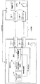
図1は、実施形態のHAクラスタシステムの全体構成及びサーバの内部構成を示す構成図である。
(A-1) Configuration of Embodiment FIG. 1 is a configuration diagram illustrating an overall configuration of an HA cluster system and an internal configuration of a server according to the embodiment.
図1において、実施形態のHAクラスタシステム1は、サーバAとサーバBの2台のサーバ間で構成される。
In FIG. 1, the
サーバA及びサーバBは、所定のサービスを提供するものである。サーバA及びサーバBは、一般的なサーバを適用することができ、そのハードウェア構成は、例えば、制御部、記憶部、通信部などを有して構成されるものである。また、サーバA及びサーバBにおけるオペレーティングシステム(OS)は、特に限定されるものではなく広く適用することができる。この実施形態では、例えばLinux(登録商標)を適用する場合を例示する。 Server A and server B provide predetermined services. A general server can be applied to the server A and the server B, and the hardware configuration thereof includes, for example, a control unit, a storage unit, a communication unit, and the like. The operating system (OS) in the server A and the server B is not particularly limited and can be widely applied. In this embodiment, for example, a case where Linux (registered trademark) is applied is illustrated.
サーバA及びサーバBは、HAクラスタを構成しており、NWスイッチを介さず、LANケーブルを直結してインタークラスタLANを構成するものである。サーバA及びサーバBは、インタークラスタLANにて、それぞれ相手サーバの死活監視やデータ同期を行うものである。 Server A and server B constitute an HA cluster, and constitute an intercluster LAN by directly connecting LAN cables without going through an NW switch. Server A and server B perform alive monitoring and data synchronization of the partner server in the intercluster LAN, respectively.
図1において、サーバA及びサーバBは、内部構成として、制御部30A及び30B、NWデバイス10A−1〜10A−2及び10B−1〜10B−2、記憶部40A及び40Bを少なくとも有する。サーバAとサーバBの内部構成は同じであるので、以下では、説明便宜上、サーバAの内部構成を説明する。
1, the server A and the server B have at least control units 30A and 30B,
NWデバイス10A−1及び10A−2は、相手サーバであるサーバBとの間でデータ通信を行う通信手段である。NWデバイス10A−1及び10A−2は、サーバBが備えるNWデバイス10B−1及び10B−2と直接LANケーブルと接続してデータ通信を行うものである。
The
なお、NWデバイス10A−1及び10A−2は、データ通信を行うことができれば種々のデバイスを適用することができ、例えば、ネットワークインターフェースカード(NIC)等を適用することができる。また、図1では、サーバAが2個のNWデバイスを有する場合を例示するが、3個以上有するようにしてもよい。
Various devices can be applied to the
制御部30Aは、サーバAの機能を司る処理部又は装置である。この実施形態において、制御部30Aは、ネットワークデバイスの冗長化を実現する冗長化機能を有する。ネットワークデバイスの冗長化機能は、複数のNWデバイス10A−1及び10A−2を監視し、いずれかのNWデバイスを用いてデータ通信させ、障害発生時に、データ通信を実行させるNWデバイスとして、他のNWデバイスに切り替える機能である。
The control unit 30A is a processing unit or device that controls the function of the server A. In this embodiment, the control unit 30A has a redundancy function for realizing redundancy of network devices. The network device redundancy function monitors a plurality of
図1に示すように、制御部30Aの冗長化機能は、bonding機能部31、NWデバイス監視・障害検出機能部32、NWデバイス切り替え機能部33を少なくとも有する。
As illustrated in FIG. 1, the redundancy function of the control unit 30 </ b> A includes at least a
bonding機能部31は、データ通信に用いるNWデバイス10A−1及び10A−2のいずれかを選択して切り替えるものである。NWデバイス10A−1及び10A−2のLANポートのリンク状態に基づいてデータ通信に用いるNWデバイスを設定するMIIリンク監視方式を採用するものである。
The
また、bonding機能部31は、NWデバイス切り替え機能部33から切り替え指示を受けると、データ通信に用いるNWデバイス10A−1及び10A−2の切り替えを行うものである。
Further, when receiving a switching instruction from the NW device switching
bonding機能部31は、例えば、Linux(登録商標)のbondingモジュールを適用することができる。bonding機能部31のbonding設定の方法は、既存のbondingモジュールの設定方法を用いることができ、例えば、実装するNWデバイス10A−1及び10A−2の設定(NWデバイス名やアドレス情報の設定等)や、パラメータの設定(例えば、動作モードの設定、MII監視のインターバル設定、優先的に動作させるNWデバイスの指定等)などを行う。各NWデバイスの設定や各パラメータの設定は予め行っておき、MIIリンク監視方式による監視結果やNWデバイス切り替え機能部33からの指示に応じて、運用するNWデバイスの切り替えを行う。
As the
NWデバイス監視・障害検出機能部32は、NWデバイス10A−1及び10A−2の通信機能を監視し、NWデバイス10A−1及び10A−2の障害を検出すると、NWデバイス切り替え機能部33に対して障害検出通知を行うものである。
The NW device monitoring / failure
NWデバイス監視・障害検出機能部32によるNWデバイス10A−1及び10A−2の障害検出は、例えば、NWデバイス10A−1及び10A−2が行うICMP(Internet Control Message Protocol)による接続確認に基づいて検出する方法を適用することができる。
The failure detection of the
例えば、NWデバイス10A−1及び10A−2が、サーバBのNWデバイス10B−1及び10B−2に対してICMP要求信号を送信する。これに対して、接続や通信機能が正常なNWデバイス10B−1及び10B−2は、ICMP応答信号をNWデバイス10A−1及び10A−2に対して返信する。NWデバイス監視・障害検出機能部32は、そのICMP応答信号がNWデバイス10A−1及び10A−2に返信されたか否かを監視している。ICMP応答信号の返信がある場合、当該NWデバイス間は正常に接続されており、両サーバのNWデバイスは正常に通信機能を動作していると判断することができる。一方、ICMP応答信号の返信がない場合には、当該NWデバイス間で何かしらの障害が生じていることを判断することができる。
For example, the
MIIリンク監視方式を採用するbonding機能部31は、LANポートのリンク状態を監視するものであり、NWデバイス自体の故障を認識することができない。しかし、この実施形態のように、NWデバイス監視・障害検出機能部32を備えることにより、NWデバイス自体の故障も検出することができる。また、正常に動作しているNWデバイスも認識することができる。
The
なお、NWデバイス監視・障害検出機能部32は、正常に動作しているNWデバイスも認識することができるので、3個以上のNWデバイスを実装する場合、障害発生時に、正常に動作しているNWデバイスを、NWデバイス切り替え機能部33に通知するようにしてもよい。この通知は、例えば、NWデバイス名やアドレス情報などの識別情報を障害検出通知に付与することで実現できる。
The NW device monitoring / failure
NWデバイス切り替え機能部33は、NWデバイス監視・障害検出機能部32から障害検出通知を受けると、bonding機能部13に対して、データ通信を実行するNWデバイス10A−1及び10A−2の切り替え指示を行うものである。
Upon receiving a failure detection notification from the NW device monitoring / failure
ここで、NWデバイス切り替え機能部33は、NWデバイス監視・障害検出機能部32の監視結果に基づいて、切り替え先のNWデバイス10A−1及び10A−2の正常動作を確認するようにしてもよい。
Here, the NW device switching
また、例えば、3個以上のNWデバイスを実装する場合に、正常動作しているNWデバイスが複数あるとき、NWデバイス切り替え機能部33は、複数のNWデバイスのうちいずれか1個のNWデバイスを選択決定するようにしてもよい。このとき、NWデバイスの選択方法は、種々の方法を適用することができるが、例えば、予め設定した順位(例えば優先順位)に従って選択する方法や、ICMP要求信号に対する応答時間が早いものを選択する方法や、ランダムに選択する方法などを適用するようにしてもよい。
Further, for example, when three or more NW devices are mounted and there are a plurality of normally operating NW devices, the NW device switching
記憶部40Aは、サーバ処理に必要なデータを記憶する記憶領域である。記憶部40Aは、相手サーバとの間で同期したデータを記憶するものである。
The
(A−2)実施形態の動作
次に、この実施形態のHAクラスタシステム1を構成するサーバのネットワークデバイスの冗長化処理の動作について図面を参照しながら説明する。
(A-2) Operation of Embodiment Next, the operation of the redundancy processing of the network device of the server constituting the
図6は、この実施形態のネットワークデバイスの冗長化処理の動作を説明する説明図である。 FIG. 6 is an explanatory diagram for explaining the operation of the redundancy processing of the network device of this embodiment.
図6において、各サーバA及びサーバBでは、MIIリンク監視方式を採用するbonding機能部31により、実装された各NWデバイスの設定及び各パラメータの設定が予め行われている。
In FIG. 6, in each server A and server B, the setting of each mounted NW device and the setting of each parameter are performed in advance by the
障害発生前、サーバA及びサーバBは、NWデバイス10A−2及び10B−2を運用デバイスとしてデータ通信しており、その後にサーバBのNWデバイス10B−2自体が故障した場合を仮定して説明する。
Before the failure occurs, the server A and the server B perform data communication using the
各サーバA及びサーバBにおいて、bonding機能部31は、MIIリンク監視方式を採用しているので、LANポートのリンク状態を監視している。NWデバイス10B−2自体が故障しても、NWデバイス10A−2及び10B−2のLANポートがリンクアップしている場合、bonding機能部31は障害を検出することができない。
In each server A and server B, the
サーバAにおいて、NWデバイス監視・障害検出機能部32は、NWデバイス10A−1とNWデバイス10B−1との間の通信機能が正常に行われているか否かを監視する(S1)。
In the server A, the NW device monitoring / failure
例えば、NWデバイス監視・障害検出機能部32は、NWデバイス10A−1が、NWデバイス10B−1に対してICMP要求信号(例えばPingコマンドの要求パケット等)を送信し、NWデバイス10B−1からICMP応答信号(例えば、Pingに対する応答パケット等)の返信があるか否かを判断する。
For example, in the NW device monitoring / failure
ここで、ICMP要求信号の送信について、NWデバイス監視・障害検出機能部32は、リンクアップした状態でNWデバイスが故障して動作が停止したことをトリガとすることができる。すなわち、LANポートはリンクアップしているが、NWデバイスがハングアップしている状態をトリガとすることができる。そして、NWデバイス監視・障害検出機能部32は、タイムアウト時間内に、ICMP要求信号に対するICMP応答信号が返信されるかどうかを判断する。
Here, with respect to the transmission of the ICMP request signal, the NW device monitoring / failure
また、サーバAにおいて、NWデバイス監視・障害検出機能部32は、上記と同様にして、NWデバイス10A−2とNWデバイス10B−2との間の通信の正常性についても監視する(S2)。
In the server A, the NW device monitoring / failure
S1の監視により、NWデバイス監視・障害検出機能部32は、NWデバイス10B−1からICMP応答信号を受信することで、NWデバイス10A−1とNWデバイス10B−1との間の通信は正常に行われていると判断する。
By monitoring S1, the NW device monitoring / failure
また、S2において、NWデバイス10B−2は故障している。NWデバイス10B−2はICMP応答信号の返信ができない。NWデバイス監視・障害検出機能部32は、所定のタイムアウト期間内に、NWデバイス10B−2からのICMP応答信号の受信を検出できない。従って、NWデバイス監視・障害検出機能部32は、NWデバイス10A−2とNWデバイス10B−2との間の通信は正常に行われていないと認識することができる。つまり、NWデバイス監視・障害検出機能部32は、相手サーバBのNWデバイス10B−2が故障していることを検出する(S3)。
In S2, the
サーバBのNWデバイス10B−2の故障を検出すると、NWデバイス監視・障害検出機能部32は、NWデバイス切り替え機能部33に対して障害検出通知を与える(S4)。
When the failure of the
NWデバイス切り替え機能部33は、NWデバイス監視・障害検出機能部32から障害検出通知を受けると、bonding機能部31に対してNWデバイスの切り替え指示を行う(S5)。
When receiving the failure detection notification from the NW device monitoring / failure
例えば、NWデバイス切り替え機能部33は、故障したNWデバイス10B−2と接続するNWデバイス10A−2側に障害が生じているので、もう一方のNWデバイス10A−1への切り替えを指示する。
For example, the NW device switching
このとき、NWデバイス切り替え機能部33は、NWデバイス監視・障害検出機能部32の監視結果を受け取り、その監視結果に基づいて切り替え先であるNWデバイス10A−1が正常に機能しているか否かを判断し、正常に機能している場合に、NWデバイス10A−1への切り替えを指示するようにしてもよい。これにより、確実に正常動作しているNWデバイスへの切り替えを行うことができるので、システムの信頼性をより高めることができる。
At this time, the NW device switching
bonding機能部31は、NWデバイス切り替え機能部33から切り替え指示を受けると、運用デバイスをNWデバイス10A−2からNWデバイス10A−1に切り替える(S6)。これにより、LANポートがリンクアップした状態でNWデバイスが故障した場合でも、データ通信を行うNWデバイスを切り替えることができる。
When receiving the switching instruction from the NW device switching
(A−3)実施形態の効果
以上のように、この実施形態によれば、NWスイッチを介さず、サーバ間を直結してインターコネクトLANを構成する場合に、MIIリンク監視方式を採用したbondingにより、安価にネットワークデバイスの冗長化を実現することができる。
(A-3) Effect of Embodiment As described above, according to this embodiment, when an interconnect LAN is configured by directly connecting servers without using an NW switch, the MII link monitoring method is used for bonding. Therefore, network device redundancy can be realized at low cost.
また、この実施形態によれば、MIIリンク監視方式のbondingにより、リンクアップしている状態でネットワークデバイスが故障した場合でも、ネットワークデバイスの切り替えができる。 Further, according to this embodiment, the network device can be switched by the MII link monitoring system bonding even when the network device fails while the link is up.
さらに、この実施形態によれば、MIIリンク監視方式のbondingによっても、LANポートの先の接続や通信の正常を監視することができる。 Further, according to this embodiment, the normal connection of the LAN port and the normal communication can be monitored also by MII link monitoring system bonding.
(B)他の実施形態
上述した実施形態で例示したHAクラスタシステムは、2台のサーバ間でクラスタシステムを構成する場合を例示したが、3台以上のサーバ間であってもよい。
(B) Other Embodiments The HA cluster system exemplified in the above-described embodiment has exemplified the case where the cluster system is configured between two servers, but may be between three or more servers.
上述した実施形態では、サーバのOSがLinux(登録商標)である場合を例示したが、これに限定されるものではない。他のOSであっても、ネットワークデバイスのリンク状態に応じてネットワークデバイスの切り替えを行う冗長機能を有するものであれば本発明を適用することができる。 In the above-described embodiment, the case where the OS of the server is Linux (registered trademark) is exemplified, but the present invention is not limited to this. The present invention can be applied to any other OS as long as it has a redundant function for switching the network device in accordance with the link state of the network device.
1…HAクラスタシステム、
10A−1及び10A−2、10B−1及び10B−2…NWデバイス、
30A及び30B…制御部、31…bonding機能部、
32…NWデバイス監視・障害検出機能部、33…NWデバイス切り替え機能部。
1 ... HA cluster system,
10A-1 and 10A-2, 10B-1 and 10B-2... NW device,
30A and 30B ... control unit, 31 ... bonding function unit,
32... NW device monitoring / failure detection function unit, 33... NW device switching function unit.
Claims (4)
上記複数の通信手段のうち、データ通信に使用する通信手段を設定する冗長化設定手段と、
上記複数の通信手段のそれぞれの通信機能を監視する通信監視手段と、
上記通信監視手段により上記データ通信に使用する通信手段の障害が検出されると、上記冗長化設定手段に対して、他の上記通信手段への切り替え指示を行う切替指示手段と
を備えることを特徴とする冗長化装置。 In a redundancy device that performs redundancy of a plurality of communication means for performing data communication with other servers that constitute a cluster system,
Among the plurality of communication means, redundancy setting means for setting communication means used for data communication,
Communication monitoring means for monitoring each communication function of the plurality of communication means;
A switching instruction means for instructing the redundancy setting means to switch to another communication means when a failure of the communication means used for the data communication is detected by the communication monitoring means. Redundant device.
上記通信監視手段が、上記複数の通信手段と上記他のサーバの通信手段との間の接続確認に基づいて監視を行うものである
ことを特徴とする請求項1に記載の冗長化装置。 The redundancy setting means performs redundancy setting of each communication means according to a link state of a port connected to the other server.
The redundancy apparatus according to claim 1, wherein the communication monitoring unit performs monitoring based on connection confirmation between the plurality of communication units and the communication unit of the other server.
コンピュータを、
上記複数の通信手段のうち、データ通信に使用する通信手段を設定する冗長化設定手段、
上記複数の通信手段のそれぞれの通信機能を監視する通信監視手段、
上記通信監視手段により上記データ通信に使用する通信手段の障害が検出されると、上記冗長化設定手段に対して、他の上記通信手段への切り替え指示を行う切替指示手段
として機能させることを特徴とする冗長化プログラム。 In a redundancy program for performing redundancy of a plurality of communication means for performing data communication with other servers constituting the cluster system,
Computer
Of the plurality of communication means, redundancy setting means for setting communication means used for data communication,
Communication monitoring means for monitoring each communication function of the plurality of communication means;
When a failure of a communication means used for the data communication is detected by the communication monitoring means, the redundancy setting means functions as a switching instruction means for instructing switching to another communication means. A redundancy program.
Priority Applications (1)
| Application Number | Priority Date | Filing Date | Title |
|---|---|---|---|
| JP2010219349A JP2012075009A (en) | 2010-09-29 | 2010-09-29 | Redundancy device and redundancy program |
Applications Claiming Priority (1)
| Application Number | Priority Date | Filing Date | Title |
|---|---|---|---|
| JP2010219349A JP2012075009A (en) | 2010-09-29 | 2010-09-29 | Redundancy device and redundancy program |
Publications (1)
| Publication Number | Publication Date |
|---|---|
| JP2012075009A true JP2012075009A (en) | 2012-04-12 |
Family
ID=46170747
Family Applications (1)
| Application Number | Title | Priority Date | Filing Date |
|---|---|---|---|
| JP2010219349A Pending JP2012075009A (en) | 2010-09-29 | 2010-09-29 | Redundancy device and redundancy program |
Country Status (1)
| Country | Link |
|---|---|
| JP (1) | JP2012075009A (en) |
Cited By (3)
| Publication number | Priority date | Publication date | Assignee | Title |
|---|---|---|---|---|
| JP2014103628A (en) * | 2012-11-22 | 2014-06-05 | Mitsubishi Electric Corp | Centralized management device, centralized management method, and program |
| JP2017083935A (en) * | 2015-10-23 | 2017-05-18 | 日本電気株式会社 | Information processor, cluster system, clustering method, and program |
| WO2021160482A1 (en) * | 2020-02-14 | 2021-08-19 | Safran Electronics & Defense | Data transmission method and many-core electronic chip |
Citations (2)
| Publication number | Priority date | Publication date | Assignee | Title |
|---|---|---|---|---|
| JP2001060959A (en) * | 1999-08-24 | 2001-03-06 | Hitachi Ltd | High reliability system |
| JP2010055509A (en) * | 2008-08-29 | 2010-03-11 | Oki Electric Ind Co Ltd | System, method, and program for fault recovery, and cluster system |
-
2010
- 2010-09-29 JP JP2010219349A patent/JP2012075009A/en active Pending
Patent Citations (2)
| Publication number | Priority date | Publication date | Assignee | Title |
|---|---|---|---|---|
| JP2001060959A (en) * | 1999-08-24 | 2001-03-06 | Hitachi Ltd | High reliability system |
| JP2010055509A (en) * | 2008-08-29 | 2010-03-11 | Oki Electric Ind Co Ltd | System, method, and program for fault recovery, and cluster system |
Cited By (4)
| Publication number | Priority date | Publication date | Assignee | Title |
|---|---|---|---|---|
| JP2014103628A (en) * | 2012-11-22 | 2014-06-05 | Mitsubishi Electric Corp | Centralized management device, centralized management method, and program |
| JP2017083935A (en) * | 2015-10-23 | 2017-05-18 | 日本電気株式会社 | Information processor, cluster system, clustering method, and program |
| WO2021160482A1 (en) * | 2020-02-14 | 2021-08-19 | Safran Electronics & Defense | Data transmission method and many-core electronic chip |
| FR3107375A1 (en) * | 2020-02-14 | 2021-08-20 | Safran Electronics & Defense | DATA TRANSMISSION PROCESS AND MANYCORE-TYPE ELECTRONIC CHIP |
Similar Documents
| Publication | Publication Date | Title |
|---|---|---|
| JP4164704B2 (en) | Network connection device switching method and network system using redundancy protocol and pseudo-redundant configuration means | |
| US6885633B1 (en) | Network node and a system | |
| KR20110086820A (en) | Redundant intermediary switch solution for detecting and managing fibre channel over ethernet (fcoe) switch failures | |
| US20070270984A1 (en) | Method and Device for Redundancy Control of Electrical Devices | |
| CN102387087A (en) | Method and system for realizing standby route based on active detection technique | |
| CN103490914A (en) | Switching system and switching method for multi-machine hot standby of network application equipment | |
| JP2004171370A (en) | Address control system and method between client/server in redundant constitution | |
| JP5480778B2 (en) | Duplex computer network system, network connection device, and fault detection and coping method | |
| JP2012075009A (en) | Redundancy device and redundancy program | |
| CN108270593B (en) | Dual-computer hot backup method and system | |
| EP2456163B1 (en) | Registering an internet protocol phone in a dual-link architecture | |
| JP2011203941A (en) | Information processing apparatus, monitoring method and monitoring program | |
| WO2010028553A1 (en) | Method, single board and system for port configuration management | |
| CN102638369B (en) | Method, device and system for arbitrating main/standby switch | |
| WO2012070274A1 (en) | Communication system and network malfunction detection method | |
| US8111625B2 (en) | Method for detecting a message interface fault in a communication device | |
| CN103001832B (en) | The detection method of distributed file system interior joint and device | |
| JP3914072B2 (en) | Network failure monitoring method, communication system, and line switching apparatus | |
| JP4692419B2 (en) | Network device, redundant switching method used therefor, and program thereof | |
| CN109510725B (en) | Communication equipment fault detection system and method | |
| JP2012222700A (en) | Node device for monitoring fault, and method for restoration from fault | |
| CN113852514A (en) | Data processing system with uninterrupted service, processing equipment switching method and connecting equipment | |
| JP2006319683A (en) | System and apparatus for monitoring network system | |
| JP2013121095A (en) | Communication device | |
| JP5459094B2 (en) | Link aggregation communication device |
Legal Events
| Date | Code | Title | Description |
|---|---|---|---|
| A711 | Notification of change in applicant |
Free format text: JAPANESE INTERMEDIATE CODE: A712 Effective date: 20120813 |
|
| A621 | Written request for application examination |
Free format text: JAPANESE INTERMEDIATE CODE: A621 Effective date: 20130515 |
|
| A977 | Report on retrieval |
Free format text: JAPANESE INTERMEDIATE CODE: A971007 Effective date: 20140217 |
|
| A131 | Notification of reasons for refusal |
Free format text: JAPANESE INTERMEDIATE CODE: A131 Effective date: 20140225 |
|
| A02 | Decision of refusal |
Free format text: JAPANESE INTERMEDIATE CODE: A02 Effective date: 20140708 |