JP2012071237A - Method and apparatus for monitoring pulse backwashing mechanism in powder collector - Google Patents
Method and apparatus for monitoring pulse backwashing mechanism in powder collector Download PDFInfo
- Publication number
- JP2012071237A JP2012071237A JP2010216939A JP2010216939A JP2012071237A JP 2012071237 A JP2012071237 A JP 2012071237A JP 2010216939 A JP2010216939 A JP 2010216939A JP 2010216939 A JP2010216939 A JP 2010216939A JP 2012071237 A JP2012071237 A JP 2012071237A
- Authority
- JP
- Japan
- Prior art keywords
- pulse
- filter
- backwashing
- backwash
- pressure
- Prior art date
- Legal status (The legal status is an assumption and is not a legal conclusion. Google has not performed a legal analysis and makes no representation as to the accuracy of the status listed.)
- Pending
Links
Images

Landscapes
- Filtering Of Dispersed Particles In Gases (AREA)
Abstract
Description
本発明は、粉体捕集用バグフィルター装置の逆洗機構に関し、とくに多数列配列されている粉体捕集フィルターの個々の逆洗時異常を検出することにより、バグフィルター全体の作業中断による工場操業の経済的損失を最小限にとどめると共に、異常フィルターや電磁弁、ダイヤフラムバルブ等異常原因となっている器具類の特定を容易にして交換・修復作業を簡便にすることを目的とする。 The present invention relates to a backwashing mechanism of a bag filter device for collecting powder, and in particular, by detecting abnormalities during backwashing of the powder collection filters arranged in multiple rows, The purpose is to minimize the economic loss of factory operations and to easily identify the equipment that is causing the abnormality, such as abnormal filters, solenoid valves, diaphragm valves, etc., and simplify the replacement and repair work.
粉体を扱う多くのプラントなどでは、例えば亜鉛や石灰などの製品や資源の回収、あるいは大気中粉塵の集塵の目的で数多くのパルス逆洗型のバグフィルターを用いた粉体捕集装置が使用されている。そのようなバグフィルターとしては、一般的に図7および図8にあらわしたような概略構造をしている。具体的にはバグフィルター1にはそれぞれ一端に電磁弁3(SV1〜SVn)およびダイヤフラムバルブ5を備えたブローチューブ6が、内部中空の長いエアヘッダー4に沿って多数本並行して設けられている。
In many plants that handle powder, for example, there are many powder collection devices that use pulse backwash type bag filters to collect products and resources such as zinc and lime, or to collect dust in the atmosphere. in use. Such a bug filter generally has a schematic structure as shown in FIGS. Specifically, the bag filter 1 is provided with a large number of
さらに、それぞれのブローチューブ6の長さ方向に沿って一定間隔毎に複数個(図では6個)の略円筒状をしたフィルター7が設置され、このようなフィルター列がバグフィルター1内に多数列設置されている。またバグフィルター1の底部にはダスト排出機2が取りつけられている。このような構成において、微粉を含むガスがバグフィルター1のガス入口1aからバググフィルター1内に導入され、内部に取り付けられたフィルター7の表面から内部へと通過する際にガス中に含まれる微粉がフィルター7の表面に捕捉される。フィルター7を通過したガスはバグフィルター1のガス出口より排出される。
Further, a plurality of (six in the figure) substantially
フィルター7の表面に捕捉された微粉は経時的に捕捉量が増え、フィルター7の抵抗(圧力損失)が増大するところから定期的に上記した各列毎にブローチューブ6から圧縮ガスを同列の各フィルター7内にブロー(パルスジェット逆流)することにより、フィルター7の表面に捕捉されていた凝集微粉を払い落とす。
The amount of fine powder trapped on the surface of the
つまりパルスジェット逆洗のための具体的な機構は通常、排気室内・外に装備されており、バグを運転している状態においては常に圧縮ガスがエアヘッダー4に供給されており、1列分のフィルター7を逆洗することが可能な噴射量のガスが蓄圧されている。ここで図示していないパルスコントローラーからの作動信号により、電磁弁3を作動(開放)すると、これに接続されているダイヤフラムバルブ5が開き、圧縮ガスがブローチューブ6のブロー孔から各フィルター7の内部に向けて瞬時に噴出し、一瞬フィルター7部分におけるガスの流れがフィルター7の内部から外部(表面側)方向に向けた逆流となる。
In other words, the specific mechanism for pulse jet backwashing is usually equipped inside and outside the exhaust chamber, and compressed gas is always supplied to the air header 4 while the bug is being operated. The amount of gas that can be back-washed is accumulated. When the
このジェットブローは音速に近いスピードで噴出するため、この際にブローされる噴出ガス量の数倍もの周囲のガスを伴ってフィルター7内に噴射されることで、フィルター7の内部のガスの流れが、フィルター7の内部からフィルター7の表面へ向けた逆の流れ(逆洗)となり、その衝撃によりフィルター7の表面に捕捉されていた凝集微粉が払い落とされてバグフィルター1の底部に自重落下させることができる。
Since this jet blow is ejected at a speed close to the speed of sound, the flow of gas inside the
このようにすることで、フィルター7の抵抗(圧力損失)の原因物質を除去してフィルター7を復元させることができる。なおバグフィルター1の底部に堆積した凝集微粉はダスト排出機により纏めて取り出されるようになっている。
By doing in this way, the causative substance of the resistance (pressure loss) of the
さらに同様の構造のものとして、ダストを回収するホッパー上にバグフィルターを立設した複数のバグフィルタ室と、上記ホッパーを介して各バグフィルタ室内へ含塵ガスを導入する含塵ガス供給配管と、バグフィルタを通過した清浄ガスを吸引する清浄ガス配管と、前記バグフィルタに逆圧をかける逆洗用気体の導入配管とを備えたもの(特開2003−38922号公報参照)が一般的に知られている。 Furthermore, as having the same structure, a plurality of bag filter chambers in which bag filters are erected on a hopper for collecting dust, and a dust gas supply pipe for introducing dust gas into each bag filter chamber via the hopper In general, there is provided a clean gas pipe for sucking clean gas that has passed through the bag filter and a backwash gas introduction pipe for applying a reverse pressure to the bag filter (see Japanese Patent Application Laid-Open No. 2003-38922). Are known.
しかし大流量の含塵ガスからの集塵にはフィルタに過大の負担がかり、濾過能力が低下するところから、バグフィルタに対してエアや不活性ガス等による逆圧をかけることにより集塵したダストをホッパーの下方に落下させて回収するための工夫がなされており、上記した特開2003−38922号公報に記載されているバグフィルタにあっては、ホッパー内にバグフィルタを通過した逆洗用の気体を吸引する逆洗気体排出配管を設けるとともに、該逆洗気体排出配管の下流側に逆洗用気体の集塵をおこなう逆洗排気専用のバグフィルタ室と、該逆洗排気専用バグフィルタ室で集塵されたガスを前記した清浄ガス配管へと導く配管とを設けるようにしている。 However, dust collection from a large flow rate of dust-containing gas places an excessive burden on the filter and reduces filtration capacity. Therefore, dust collected by applying a back pressure to the bag filter with air, inert gas, etc. The bag filter described in Japanese Patent Application Laid-Open No. 2003-38922 is used for backwashing that has passed through the bag filter. And a bag filter chamber exclusively for backwashing exhaust that collects backwashing gas on the downstream side of the backwashing gas discharge piping, and a bag filter dedicated for backwashing exhaust. A pipe that guides the gas collected in the chamber to the clean gas pipe is provided.
また吸気口と排気口とを有したハウジング内に、被処理ガスに含まれる塵埃を除去するための筒状の濾過フィルターを設置するとともに、その上方部に濾過処理後の処理ガスに含まれる有害成分を除去するための吸着フィルターを設け、さらに上記濾過フィルターと吸着フィルターとの間に、濾過フィルターに対して圧縮空気を供給するエアノズルを設けるとともに、濾過フィルターに付着した捕捉塵埃を逆洗によって分離し、これをハウジングの下方に設けた塵埃回収装置にて回収するようにして濾過フィルターの逆洗に伴う有害成分を除去するようにしたものも知られている(特開2002−35523号公報参照)。 In addition, a cylindrical filtration filter for removing dust contained in the gas to be treated is installed in a housing having an intake port and an exhaust port, and harmful gas contained in the treated gas after the filtration treatment is disposed above the filter. An adsorption filter for removing components is installed, and an air nozzle that supplies compressed air to the filtration filter is installed between the filtration filter and the adsorption filter, and trapped dust adhering to the filtration filter is separated by backwashing. In addition, there is also known one that removes harmful components accompanying backwashing of the filtration filter by collecting it with a dust collecting device provided below the housing (see JP 2002-35523 A). ).
さらにバグフィルターの集塵前の排ガス吸引室と集塵後の排ガス吸引室間での圧力差を検出することにより濾布の目詰まり状態と差圧との関係から逆洗すべきバグフィルターを見出すようにしたものも知られている(特開2001−300237号公報参照)。またバグフィルターの濾過材の逆洗に対する耐久性を向上させるために、中空率を5〜50%、比溶積を50立方cm/g以上、圧縮率を75%以下とした中空断面ポリフェニレンサルファイド短繊維を30%以上使用した不織布を少なくとも1層以上用いたフィルター用のフェルトを用いるようにしたもの等も知られている(特開2008−179938号公報参照)。 Furthermore, by detecting the pressure difference between the exhaust gas suction chamber before dust collection and the exhaust gas suction chamber after dust collection, a bag filter to be backwashed is found from the relationship between the clogged state of the filter cloth and the differential pressure. Such a device is also known (see Japanese Patent Application Laid-Open No. 2001-300377). Moreover, in order to improve the durability against backwashing of the filter material of the bag filter, the hollow section polyphenylene sulfide short with a hollow ratio of 5 to 50%, a specific dissolution product of 50 cubic cm / g or more, and a compression ratio of 75% or less. Also known is a filter felt using at least one layer of non-woven fabric containing 30% or more of fibers (see JP 2008-179938).
しかしながら、上記したいずれのものにあっても、バグフィルターを備えた集塵装置のガス入口および出口側に静圧の圧力測定ノズルを設け、運転中のフィルターの差圧(△P:圧力損失)を測定し、差圧の上昇変化からバグフィルター濾材の目詰まり具合による濾材寿命を間接的に知るものである。つまり基本的には集塵装置の運転状況の確認に関して、バグフィルターにかかる差圧を検出して異常の有無を間接的に推定確認するものであり、そのために専らバグフィルター全体についての異常の有無を確認するだけのものであった。 However, in any of the above, static pressure measurement nozzles are provided on the gas inlet and outlet sides of a dust collector equipped with a bag filter, and the differential pressure of the filter during operation (ΔP: pressure loss) , And indirectly know the filter media life due to the clogging condition of the bag filter media from the change in the differential pressure. In other words, basically, regarding the confirmation of the operating status of the dust collector, the differential pressure applied to the bag filter is detected and the presence or absence of abnormality is indirectly estimated and confirmed. It was just to confirm.
また、大型の集塵装置では装置内の捕集フィルターの設置数が多くなり、パルス逆流が数十列におよぶものも珍しくはない。その場合に1部のパルス逆洗機構の作動不良発生により有効濾過面積が減少して圧損が上昇しても、これを的確に確認することができないために、圧損上昇の原因を単に捕集フィルターの濾布の目詰まりによる寿命である、との間違った判定に基づいてすべての捕集フィルターを交換してしまうことも多く経済的損失も大きいといえる。 Moreover, in a large dust collector, the number of collection filters installed in the device increases, and it is not uncommon for the pulse backflow to reach several tens of rows. In that case, even if the effective filtration area decreases due to the malfunction of one part of the pulse backwash mechanism and the pressure loss rises, this cannot be confirmed accurately. It can be said that all the collection filters are replaced based on the erroneous determination that the service life is due to clogging of the filter cloth, and the economic loss is great.
つまり、従来の集塵装置におけるパルス逆洗機構の監視方法ではバグフィルターのガス入口および出口側に設置した圧力測定ノズルにより集塵装置運転中の逆洗時におけるバグフィルター内の差圧変化をみるために、パルス逆洗機構の一部に不具合を生じて集塵装置の作動不良が判明した場合に、どの列の捕集フィルターに異常があるのか具体的に特定することができない。その結果まだ使える捕集フィルターをすべて交換してしまったり、あるいはすべての列の逆洗部についての点検を実施する必要がある等の課題があった。 In other words, in the conventional monitoring method of the pulse backwashing mechanism in the dust collector, the pressure measurement nozzles installed on the gas inlet and outlet sides of the bagfilter are used to see the change in differential pressure in the bagfilter during backwashing during dust collector operation. Therefore, when a malfunction occurs in a part of the pulse backwashing mechanism and the malfunction of the dust collector is found, it is not possible to specifically identify which column of the collection filter is abnormal. As a result, there was a problem that it was necessary to replace all the collection filters that could still be used, or to inspect the backwash sections of all the rows.
また上記の差圧圧損の原因は、捕集フィルターの濾布の目詰まりに限ったことではなく、たとえば逆洗機構を構成する個々のダイヤフラム弁や電磁弁に異常があった場合においてもバグフィルター内における差圧の異常を感知することになり、集塵装置のガス入口および出口側に設置した圧力測定ノズルにより運転中のバグフィルター内の差圧変化をみるだけでは、差圧変化の原因がいずれかの捕集フィルターの目詰まりであるのか、それとも逆洗機構を構成する個々のダイヤフラム弁や電磁弁異常であるのかについて特定することができない。 Moreover, the cause of the above-mentioned differential pressure loss is not limited to clogging of the filter cloth of the collection filter. For example, even when there is an abnormality in each diaphragm valve or electromagnetic valve constituting the backwash mechanism, the bag filter The pressure difference is detected in the bag filter during operation by the pressure measurement nozzles installed at the gas inlet and outlet sides of the dust collector. It cannot be specified whether any of the collection filters is clogged or whether each diaphragm valve or electromagnetic valve constituting the backwash mechanism is abnormal.
そこで、本発明においてはパルス逆洗機構を備えた複数個の捕集フィルターによるフィルター列を少なくとも複数列設置したバグフィルターにおいて、各列毎の捕集フィルターのパルス逆洗機構の異常発生箇所を特定することができるようにしたものである。 Therefore, in the present invention, in a bug filter in which at least a plurality of filter rows by a plurality of collection filters having a pulse backwashing mechanism are installed, an abnormality occurrence point of the pulse backwashing mechanism of the collection filter for each row is specified. It is something that can be done.
具体的には、パルス逆洗機構を備えた少なくとも複数列のフィルター群の、それぞれのパルス逆洗用エアヘッダー内圧変化を監視し、パルス逆洗直前における内圧があらかじめ設定された高圧基準値に達しない場合、または逆洗直後における内圧があらかじめ設定された低圧基準値より下回らないか、低圧基準値を下回っても再度高圧基準値以上に復帰しない場合に異常発生の判定をおこなうようにした粉体捕集装置におけるパルス逆洗機構の監視方法に関する。 Specifically, changes in the internal pressure of the air header for pulse backwashing of at least multiple rows of filter groups equipped with a pulse backwashing mechanism are monitored, and the internal pressure immediately before the pulse backwashing reaches a preset high pressure reference value. If the internal pressure immediately after backwashing does not fall below the preset low-pressure reference value, or falls below the low-pressure reference value and does not return to the high-pressure reference value or higher again, the powder is judged to be abnormal. The present invention relates to a monitoring method of a pulse backwashing mechanism in a collection device.
また本発明は、複数個のフィルターを連設させた少なくとも複数列のフィルター群と、それぞれのフィルター群に備えられたパルス逆洗機構と、パルス逆洗監視手段とからなり、パルス逆洗機構は各列のフィルター群のフィルター内に逆洗用高圧ガスを噴射するエアヘッダーと、該エアヘッダー内のガスを各列のフィルター内に噴射させるための、それぞれの列毎に設置された電磁弁およびダイヤフラムバルブと、電磁弁およびダイヤフラムバルブを作動させるパルスコントローラーとからなるとともに、パルス逆洗監視手段はあらかじめエアヘッダー内ガス圧について、逆洗開始前のエアヘッダー内の高圧設定値(PS−H)と、逆洗後のエアヘッダー内の低圧設定値(PS−L)とが設定されており、パルス逆洗の前後におけるエアヘッダー内ガス圧の変化を捉えて異常の検出監視をおこなうようにしたパルス逆洗機構の監視装置に関する。 Further, the present invention comprises at least a plurality of rows of filter groups in which a plurality of filters are arranged in series, a pulse backwashing mechanism provided in each filter group, and a pulse backwash monitoring means. An air header that injects backwashing high-pressure gas into the filter of each row of filter groups, and a solenoid valve installed in each row for injecting the gas in the air header into the filter of each row; It consists of a diaphragm valve and a pulse controller that operates the solenoid valve and the diaphragm valve. The pulse backwash monitoring means pre-sets the gas pressure in the air header in advance, and the high pressure set value (PS-H) in the air header before the start of backwashing. And the low pressure set value (PS-L) in the air header after backwashing is set. It captures the changes in over the gas pressure about the monitoring system of the pulse back washing mechanism to perform the abnormality detection monitoring.
本発明は上記したように、パルス逆洗機構を備えた複数個の捕集フィルターによるフィルター列を少なくとも複数列設置したバグフィルターにおいて、パルス逆洗機構におけるダイヤフラムバルブを作動させるためのパルスコントローラーの作動信号と逆洗時におけるエアヘッダー内の圧力変化との対比により各フィルター列毎の異常発生の有無を監視するようにしたために、各フィルター列毎のパルス逆洗機構の異常発生箇所を特定することができ、異常発生が認められた列のみ捕集フィルターの操業を中止して修復作業をおこなえばよく、バグフィルター全体を操業停止する必要がないためにバグフィルターの操業停止による影響が少なくて済む。 As described above, the present invention provides an operation of a pulse controller for operating a diaphragm valve in a pulse backwashing mechanism in a bag filter in which at least a plurality of filter rows by a plurality of collection filters having a pulse backwashing mechanism are installed. Since the occurrence of abnormalities in each filter row is monitored by comparing the signal with the pressure change in the air header during backwashing, the location of abnormalities in the pulse backwash mechanism for each filter row must be identified. It is only necessary to stop the operation of the collection filter and perform repair work only on the columns where anomalies are observed, and it is not necessary to stop the operation of the entire bug filter. .
また、異常発生が認められたフィルター列の異常内容については、逆洗機構を構成する個々のダイヤフラム弁や電磁弁の異常発生に起因する場合について確認することができるために、不用意にフィルターのみを交換してしまうことがなく、修復作業の効率化をはかることができる。 In addition, regarding the abnormal contents of the filter row where the occurrence of abnormality is recognized, it is possible to confirm the cases caused by the abnormal occurrence of individual diaphragm valves and solenoid valves that constitute the backwash mechanism. It is possible to improve the efficiency of the repair work.
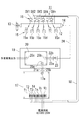
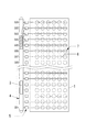
以下において本発明の実施の形態について詳細に説明をする。図1には多数列の捕集フィルターを備えたバグフィルター装置の概略をあらわした平面図が記載されている。なお同図においてバグフィルターの基本的な構造そのものについては従来のもの(図7および図8にあらわしたもの)と変わらないのでその部分の図を省略しているが、図1において11はパルス逆洗機構、17はパルスコントローラー、19は各フィルター列毎の異常発生の有無を監視するパルス逆洗監視手段をあらわしている。 Hereinafter, embodiments of the present invention will be described in detail. FIG. 1 is a plan view showing an outline of a bag filter device provided with multiple rows of collection filters. In this figure, the basic structure of the bag filter itself is the same as that of the conventional one (shown in FIGS. 7 and 8), so the illustration of that portion is omitted. In FIG. A washing mechanism, 17 is a pulse controller, and 19 is a pulse backwash monitoring means for monitoring the presence or absence of an abnormality for each filter row.
パルス逆洗機構11は、各列のそれぞれの捕集フィルターに対してパルスジェット逆洗ガスを噴射するための長円筒状をしたエアヘッダー12と、各列毎のフィルター列に逆洗ガスを噴射するダイヤフラムバルブ15および該ダイヤフラムバルブ15を作動させるべくパルスコントローラー17からの作動信号により作動(開放)される電磁弁16とから構成される。
The
パルスコントローラー17は、ターミナルT1〜Tnが設けられ、各列毎の電磁弁SV1〜SVnに、それぞれ電気的に接続されるターミナルT1〜Tnと、電源(AC100V/200V)に接続されるターミナルV1・V2が設けられている。なお図1において18はターミナルT1〜Tnと電磁弁SV1〜SVnに、それぞれ電気的に接続されるリード線の束をあらわしており、また17aは後記する逆洗監視基板20に接続するための接続部をあらわしている。
The
さらに異常発生の有無を監視するパルス逆洗監視手段19は、前記したパルスコントローラー17の作動信号と逆洗時におけるエアヘッダー12内の圧力変化との対比により各フィルター列毎の異常発生の有無を監視するものである。そのような監視手段として本実施例の場合においてはパルス逆洗部監視盤19が構成されている。パルス逆洗部監視盤19は、逆洗監視基板20と、該基盤20に設けられた接続部20a、20b、20cとからなり、接続部20aには前記したパルス逆洗基板17の接続部17aとの間にケーブル21a・21bを介在させて電気的に接続されている。
Furthermore, the pulse backwash monitoring means 19 for monitoring the presence or absence of an abnormality indicates whether or not an abnormality has occurred for each filter row by comparing the operation signal of the
つぎに逆洗監視基板20の接続部20bにはケーブル22a・22bを介してプレッシャースイッチ(PS)23が設けられており、さらにこのプレッシャースイッチ23は既述したパルス逆洗機構11におけるエアヘッダー12の一端に設けられた接続部14との間にチューブ24を介して接続されている。
Next, a pressure switch (PS) 23 is provided on the connecting
上記の構成において、パルスジェット逆洗のための基本構造については従来技術の項においても既述したように、通常、排気室内・外に装備されており、バグフィルターを運転している状態においては常に圧縮ガスがエアヘッダー12に供給されており、エアヘッダー12内には1列分のフィルター(図示省略)を逆洗することが可能な噴射量のガスが蓄圧されている。
In the above configuration, the basic structure for pulse jet backwashing is usually installed inside and outside the exhaust chamber as described in the section of the prior art, and in the state where the bag filter is in operation. Compressed gas is always supplied to the
ここでパルスコントローラー17からターミナルT1〜Tnに沿って一定の時間毎に順次送られる作動信号により、電磁弁SV1〜SVnを順次作動(開放)させると、これに接続されているダイヤフラムバルブ15a〜15nが開き、エアヘッダー12内の圧縮ガスが図示していないブローチューブのブロー孔から各フィルターの内部に向けて瞬時に噴出される。
Here, when the solenoid valves SV1 to SVn are sequentially operated (opened) by the operation signals sequentially sent from the
この瞬間にフィルター部分におけるガスの流れがフィルターの内部から外部(表面側)方向に向けた逆流となり、このジェットブローにより実際にブローされる噴出ガス量の数倍もの周囲のガスを伴ってフィルター内に噴射されることで、フィルター内部のガスの流れが、フィルターの内部からフィルターの表面へ向けた逆の流れ(逆洗)となり、その衝撃によりフィルターの表面に捕捉されていた凝集微粉が払い落とされてバグフィルターの底部に自重落下させることができる。 At this moment, the gas flow in the filter part becomes a reverse flow from the inside of the filter to the outside (surface side) direction, and the inside of the filter is accompanied by surrounding gas several times the amount of jet gas actually blown by this jet blow. As a result, the gas flow inside the filter becomes a reverse flow (backwashing) from the inside of the filter to the surface of the filter, and the aggregated fine powder trapped on the surface of the filter by the impact is wiped off. It can be dropped by its own weight on the bottom of the bag filter.
このようにすることで、フィルターの抵抗(圧力損失)の原因物質を除去して各フィルターの機能を回復させることができる。さらにこの場合に、パルス逆洗基板17の各ターミナル、たとえばT1から電磁弁SV1への作動出力が発せられる際に、同時に接続部17aからケーブル21a・21bを介して接続部20aにより逆洗監視基板20にも電磁弁SV1への作動出力をする。
By doing in this way, the function of each filter can be recovered by removing the causative substance of the resistance (pressure loss) of the filter. Further, in this case, when an operation output from each terminal of the
パルス逆洗基板17のターミナルT1からの作動出力信号を受けて電磁弁SV1が作動し、さらにダイヤフラムバルブ15aが作動してエアヘッダー12内より圧縮ガスが噴出し、これに伴ってエアヘッダー12の内部圧力が降下する。このときプレッシャースイッチ(PS)23がエアヘッダー12内のガス圧変化を検知し、これを逆洗監視基板20に出力する。
In response to the operation output signal from the terminal T1 of the
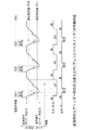
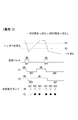
逆洗監視基板20のプレッシャースイッチ(PS)23には、あらかじめ逆洗開始前のエアヘッダー12内の高圧設定値(PS−H)と、逆洗後のエアヘッダー12内の低圧設定値(PS−L)とが設定されており、図2にもあらわしたようにパルス逆洗の前後において、逆洗前のエアヘッダー12の内圧が高圧設定値(PS−H)を超えていれば正常で、また逆洗直後のエアヘッダー12の内圧が低圧設定値(PS−L)を下回れば正常と判定される。
The pressure switch (PS) 23 of the
なお、この場合にパルス逆洗基板17から逆洗信号が出たにもかかわらず、エアヘッダー12内のガス圧が下がらなかったり(PS−H異常)、あるいは逆洗直後にエアヘッダー12内のガス圧力が回復しない場合(PS−L異常)には異常の判定がなされ、逆洗監視基板20の接続部20cより作動異常出力がなされ、これに接続されている音声的または視覚的等の警報手段により警報が発せられる(なお図面においては説明の便宜上から、正常:○、異常:●、出力異常:×の表示であらわしている)。
In this case, the gas pressure in the
逆洗監視基板20より発せられる作動異常出力信号とバグフィルターの実際の不具合との関連について示せば概ね以下の通りである。
The relationship between the abnormal operation output signal generated from the
PS−H異常(逆洗信号が出たにもかかわらず、エアヘッダー12内の圧力が下がらない場合)
(1)ダイヤフラムバルブ15が開かない
(2)電磁弁16が開かない
(3)パルス逆洗基板(パルスコントローラー)17の出力異常
PS-H error (when the pressure in the
(1)
PS−L異常(逆洗後エアヘッダー12内の圧力が復帰しない場合)
(1)ダイヤフラムバルブ15が閉まらない
(2)電磁弁16が閉まらない
PS-L error (when pressure in
(1)
上記した一連の動作が各列毎に実施される。すなわち逆洗は電磁弁SV1〜SVnについて、同時ではなく1列毎に順番に実施されるようにパルス逆洗基板17より順次作動出力がなされる。
The series of operations described above is performed for each column. That is, the backwashing is sequentially performed from the
《異常例−1》
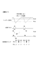
この場合に、図3にあらわしたように逆洗時において、パルス逆洗基板17から逆洗信号が出たにもかかわらず、エアヘッダー12内のガス圧が高圧設定値(PS−H)より減圧しない場合には、電磁弁16が作動しないか、あるいはダイヤフラムバルブ15が開かない等の異常が想定される。
<< Abnormal Case-1 >>
In this case, as shown in FIG. 3, the gas pressure in the
したがってこの場合には表示ランプとして低圧設定値(PS−L)側のランプは正常(白)が、また高圧設定値側(PS−H)のランプの不具合箇所(図3の場合にはSV2)が異常(黒)の点灯をする。 Therefore, in this case, the low-pressure set value (PS-L) side lamp is normal (white) as the display lamp, and the high-pressure set value side (PS-H) lamp is defective (SV2 in the case of FIG. 3). Lights up abnormally (black).
《異常例−2》
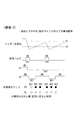
図4にあらわしたように、逆洗直後にエアヘッダー12内のガス圧が低圧設定値(PS−L)よりは下回るものの、高圧設定値(PS−H)を超えない場合については、まず供給ガス圧不足、ガス配管の漏れ、などの異常が想定される。
<< Abnormal Case-2 >>
As shown in FIG. 4, when the gas pressure in the
この場合には表示ランプとして低圧設定値(PS−L)側のランプは正常(白)が、高圧設定値側(PS−H)のランプの不具合箇所(図3の場合には電磁弁SV2、SV−3以降)が異常(黒)の点灯をする。なお上記の場合に異常出力信号は、異常個所が復元されて正常化されると上書きされて正常点灯する。 In this case, the low-pressure set value (PS-L) side lamp is normal (white) as the display lamp, but the high-pressure set value side (PS-H) lamp is defective (in the case of FIG. 3, the solenoid valve SV2, SV-3 or later) lights up abnormally (black). In the above case, the abnormal output signal is overwritten and overwritten normally when the abnormal part is restored and normalized.
《異常例−3》
図5にあらわしたように、逆洗直後にエアヘッダー12内のガス圧が低圧設定値(PS−L)より下回ったまま回復の兆しが見えない場合には、電磁弁16あるいはダイヤフラムバルブ15が開きっぱなしであることが想定される。この場合における表示ランプは電磁弁SV2以降の高圧設定値(PS−H)側は正常(白)であるものの低圧設定値(PS−L)側のランプが異常(黒)を示す。
<Abnormal Case-3>
As shown in FIG. 5, when the gas pressure in the
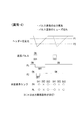
《異常例−4》
図6にあらわしたように、電磁弁SV1についての逆洗が正常であったにもかかわらずSV2についての逆洗パルスが発せられず、エアヘッダー12内のガス圧が高圧設定値(PS−H)を下回らない場合においては逆洗パルスコントロール基板17のヒューズ切断、あるいはパルス逆洗基板17自体の異常が想定される。
<< Abnormal Case-4 >>
As shown in FIG. 6, the backwashing pulse for SV2 is not issued even though the backwashing for the solenoid valve SV1 is normal, and the gas pressure in the
異常発生箇所が特定された場合に、その部分の部品を交換し、あるいは修復することによりバグフィルターなどパルス逆洗機構の機能回復をはかることができる。 When an abnormality occurrence point is specified, the function of the pulse backwashing mechanism such as a bag filter can be recovered by replacing or repairing the part of the part.
11 パルス逆洗機構
12 エアヘッダー
13 圧縮ガス供給部
14 接続部
15 ダイヤフラムバルブ
15a〜f ダイヤフラムバルブ
16 電磁弁
17 パルス逆洗基板(パルスコントローラー)
18 リード線
19 パルス逆洗部監視盤
20 逆洗監視基板
20a 接続部
20b 接続部
20c 接続部
21a ケーブル
21b ケーブル
22a ケーブル
22b ケーブル
23 プレッシャースイッチ(PS)
PS−H 高圧設定値
PS−L 低圧設定値
DESCRIPTION OF
18
PS-H High pressure set value PS-L Low pressure set value
Claims (2)
It consists of at least a plurality of rows of filter groups in which a plurality of filters are arranged, a pulse backwashing mechanism provided in each filter group, and a pulse backwash monitoring means. The pulse backwashing mechanism is a filter group in each row. An air header that injects backwashing high-pressure gas into the filter, a solenoid valve and a diaphragm valve installed in each row for injecting the gas in the air header into the filter in each row, and an electromagnetic It consists of a pulse controller that operates the valve and the diaphragm valve, and the pulse backwash monitoring means pre-checks the gas pressure in the air header, the high pressure set value (PS-H) in the air header before starting the backwash, and after the backwash The low pressure set value (PS-L) in the air header is set, and the gas pressure in the air header before and after the pulse backwashing Of monitor pulse back washing mechanism to perform the abnormality detection monitor captures.
Priority Applications (1)
| Application Number | Priority Date | Filing Date | Title |
|---|---|---|---|
| JP2010216939A JP2012071237A (en) | 2010-09-28 | 2010-09-28 | Method and apparatus for monitoring pulse backwashing mechanism in powder collector |
Applications Claiming Priority (1)
| Application Number | Priority Date | Filing Date | Title |
|---|---|---|---|
| JP2010216939A JP2012071237A (en) | 2010-09-28 | 2010-09-28 | Method and apparatus for monitoring pulse backwashing mechanism in powder collector |
Publications (1)
| Publication Number | Publication Date |
|---|---|
| JP2012071237A true JP2012071237A (en) | 2012-04-12 |
Family
ID=46167628
Family Applications (1)
| Application Number | Title | Priority Date | Filing Date |
|---|---|---|---|
| JP2010216939A Pending JP2012071237A (en) | 2010-09-28 | 2010-09-28 | Method and apparatus for monitoring pulse backwashing mechanism in powder collector |
Country Status (1)
| Country | Link |
|---|---|
| JP (1) | JP2012071237A (en) |
Cited By (3)
| Publication number | Priority date | Publication date | Assignee | Title |
|---|---|---|---|---|
| JP2017513705A (en) * | 2014-04-25 | 2017-06-01 | プライメタルズ・テクノロジーズ・オーストリア・ゲーエムベーハー | Monitoring pressurized gas-based cleaning processes in hose filter equipment |
| CN110559758A (en) * | 2019-10-15 | 2019-12-13 | 江西博鑫精陶环保科技有限公司 | High-pressure pulse slow-release back-blowing structure for high-temperature wall-flow ceramic membrane dust removal equipment |
| CN110613992A (en) * | 2019-09-27 | 2019-12-27 | 合肥中亚环保科技有限公司 | Intelligent fault judgment method for pulse ash removal valve of bag type dust collector |
Citations (3)
| Publication number | Priority date | Publication date | Assignee | Title |
|---|---|---|---|---|
| JPS62174618U (en) * | 1986-04-24 | 1987-11-06 | ||
| JPH05184834A (en) * | 1992-01-13 | 1993-07-27 | Kawasaki Steel Corp | Filter cleaning device for bag filter |
| JPH05184835A (en) * | 1992-01-13 | 1993-07-27 | Kawasaki Steel Corp | Dry dust collector |
-
2010
- 2010-09-28 JP JP2010216939A patent/JP2012071237A/en active Pending
Patent Citations (3)
| Publication number | Priority date | Publication date | Assignee | Title |
|---|---|---|---|---|
| JPS62174618U (en) * | 1986-04-24 | 1987-11-06 | ||
| JPH05184834A (en) * | 1992-01-13 | 1993-07-27 | Kawasaki Steel Corp | Filter cleaning device for bag filter |
| JPH05184835A (en) * | 1992-01-13 | 1993-07-27 | Kawasaki Steel Corp | Dry dust collector |
Cited By (4)
| Publication number | Priority date | Publication date | Assignee | Title |
|---|---|---|---|---|
| JP2017513705A (en) * | 2014-04-25 | 2017-06-01 | プライメタルズ・テクノロジーズ・オーストリア・ゲーエムベーハー | Monitoring pressurized gas-based cleaning processes in hose filter equipment |
| CN110613992A (en) * | 2019-09-27 | 2019-12-27 | 合肥中亚环保科技有限公司 | Intelligent fault judgment method for pulse ash removal valve of bag type dust collector |
| CN110559758A (en) * | 2019-10-15 | 2019-12-13 | 江西博鑫精陶环保科技有限公司 | High-pressure pulse slow-release back-blowing structure for high-temperature wall-flow ceramic membrane dust removal equipment |
| CN110559758B (en) * | 2019-10-15 | 2024-05-14 | 江西博鑫环保科技股份有限公司 | High-pressure pulse slow-release blowback structure for high-temperature wall-flow ceramic membrane dust removal equipment |
Similar Documents
| Publication | Publication Date | Title |
|---|---|---|
| KR102324738B1 (en) | Monitoring of a pressurized gas-based cleaning process in a hose filter installation | |
| US20110023709A1 (en) | Dust collector control system | |
| US9662604B2 (en) | Telescopic cleaning system for exhaust air filters | |
| CN111346440A (en) | Intelligent electromagnetic pulse valve fault detection system and detection method thereof | |
| JP2004534646A5 (en) | ||
| JP2012071237A (en) | Method and apparatus for monitoring pulse backwashing mechanism in powder collector | |
| JP2007130566A (en) | Breakage sensing method of filter cloth of dust collector | |
| CN109152973A (en) | A kind of dust arrester diaphragm valve of manual-operated emergent operation | |
| CN212039455U (en) | Dust remover and dust remover pressure differential detecting system | |
| JP4117566B2 (en) | Bug filter and its operation method | |
| CN108928640B (en) | Filter monitoring in pneumatic transport system | |
| JP3846320B2 (en) | Electronic component mounting apparatus and air blow circuit abnormality detection method in electronic component mounting apparatus | |
| US7402189B2 (en) | Autonomously-cleaned conditioning system | |
| JPH05184834A (en) | Filter cleaning device for bag filter | |
| US6911062B1 (en) | Filter assembly utilizing dual filter elements and a pressure responsive member to provide differential pressure actuated switchover | |
| EP2556878A1 (en) | A system and a method for detecting a local operation condition in an individual filter unit or in a group of filter units in a filter device | |
| JPH09206532A (en) | Abnormality monitoring method of dust collecting device | |
| JPH08503654A (en) | Method for cleaning a filter bag of a bag filter device | |
| KR950011086B1 (en) | The action controoled system of collecting apparatus | |
| JP2001219581A (en) | Ink-jet recording apparatus | |
| CN215782309U (en) | Dust removal system | |
| KR101623335B1 (en) | Impinger control system | |
| CN106338846B (en) | Wet type equipment | |
| CN218482207U (en) | Vacuum generator with gas filtering device for packaging equipment | |
| CN1246095C (en) | High-pressure descaling failure detecting apparatus |
Legal Events
| Date | Code | Title | Description |
|---|---|---|---|
| A621 | Written request for application examination |
Free format text: JAPANESE INTERMEDIATE CODE: A621 Effective date: 20130809 |
|
| A977 | Report on retrieval |
Free format text: JAPANESE INTERMEDIATE CODE: A971007 Effective date: 20140326 |
|
| A131 | Notification of reasons for refusal |
Free format text: JAPANESE INTERMEDIATE CODE: A131 Effective date: 20140513 |
|
| A02 | Decision of refusal |
Free format text: JAPANESE INTERMEDIATE CODE: A02 Effective date: 20141125 |